EP2030519A2 - Slider for slide fastener - Google Patents
Slider for slide fastener Download PDFInfo
- Publication number
- EP2030519A2 EP2030519A2 EP20080252816 EP08252816A EP2030519A2 EP 2030519 A2 EP2030519 A2 EP 2030519A2 EP 20080252816 EP20080252816 EP 20080252816 EP 08252816 A EP08252816 A EP 08252816A EP 2030519 A2 EP2030519 A2 EP 2030519A2
- Authority
- EP
- European Patent Office
- Prior art keywords
- pull tab
- slider
- slide fastener
- main body
- bridge portion
- Prior art date
- Legal status (The legal status is an assumption and is not a legal conclusion. Google has not performed a legal analysis and makes no representation as to the accuracy of the status listed.)
- Withdrawn
Links
Images








Classifications
-
- A—HUMAN NECESSITIES
- A44—HABERDASHERY; JEWELLERY
- A44B—BUTTONS, PINS, BUCKLES, SLIDE FASTENERS, OR THE LIKE
- A44B19/00—Slide fasteners
- A44B19/24—Details
- A44B19/26—Sliders
-
- A—HUMAN NECESSITIES
- A44—HABERDASHERY; JEWELLERY
- A44B—BUTTONS, PINS, BUCKLES, SLIDE FASTENERS, OR THE LIKE
- A44B19/00—Slide fasteners
- A44B19/24—Details
- A44B19/26—Sliders
- A44B19/262—Pull members; Ornamental attachments for sliders
Definitions
- the present invention relates to a slider for a slide fastener, capable of reducing sound generated by a contact between a slider body and a pull tab.
- a slide fastener is attached to an opening in order to easily open/close the opening in clothes, bag or the like.
- the slide fastener is constructed by arranging a plurality of fastener elements on each of element attaching edge portions opposing each other of right and left fastener tapes so as to form a pair of right and left fastener stringers, and then placing a slider on the right and left element rows composed of the plurality of fastener elements disposed on the right and left fastener stringers.
- a slider has a slider body to be placed on the element rows and a pull tab attached to the slider body.
- the slider body is often made of metal and generally, includes upper and lower blades, a connecting post for connecting the upper and lower blades at a front end portion of the slider, right and left flanges formed on right and left side edges of the upper blade and/or the lower blade, and a pull tab attaching post erected on the surface (top surface) of the upper blade along the back-forth direction of the slider.
- Right and left shoulder mouths are formed on the front end side of the slider body such that they are divided by the connecting post while a rear mouth is formed at a rear end of the slider body. Further, a Y-shaped element guide passage which brings the right and left shoulder mouths and the rear mouth in communication with each other is disposed between the upper and lower blades.
- the pull tab has a connecting portion for connecting one end thereof to the pull tab attaching post provided on the slider body and a grip portion disposed on the other end of the connecting portion.
- a slider 74 is placed on element rows 73 of the pair of right and left fastener stringers 72.
- the slider 74 in this patent document 1 includes a slider body 75 and a pull tab 76.
- the slider body 75 includes an upper blade, a lower blade, a connecting post, right and left flanges, and an inverted U-shaped pull tab attaching post 75a.
- the pull tab 76 has a connecting body 77 and a grip portion 78.
- the connecting portion 77 includes a first attaching portion 77a which is constituted of a hole portion formed at one end portion thereof and a second attaching portion 77b which is composed of a ring-like limb disposed at the other end portion thereof.
- the connecting body 77 is installed onto the slider body 75 by inserting the first attaching portion 77a into the inverted U-shaped pull tab attaching post 75a disposed on the slider body 75 in a cantilevered state such that the attaching post 75a is hooked on the slider body 75, and thereafter deforming the pull tab attaching post 75a plastically so that the connecting body 77 does not slip out of the pull tab attaching post 75a.
- the grip portion 78 has a first main body portion (surface half portion) 78a, a second main body portion (rear surface half portion) 78b, and a neck portion 78c for connecting the first and second main body portions 78a, 78b.
- the first surface (inner side face) of the first main body portion 78a of the grip portion 78 has a plurality of loops 78d which constitute a surface fastener
- the first surface (inner side face) of the second main body portion 78b has a plurality of hooks 78e which constitute a surface fastener.
- the grip portion 78 having the plurality of loops 78d and the plurality of hooks 78e is installed onto the connecting body 77 by overlapping the first main body portion 78a and the second main body portion 78b after the first main body portion 78a or the second main body portion 78e is inserted into the second attaching portion (limb) 77b of the connecting body 77 so as to engage the hooks 78e of the second main body portion 78b with the loops 78d of the first main body portion 78a.
- the slide fastener 71 of the patent document 1 can be manufactured at a lower cost than, for example, a slide fastener using a rivet for attaching the grip portion 78.
- the grip portion 78 can be formed into a desired shape by, for example, cutting out the surface fastener into a predetermined shape.
- the grip portion 78 can have ample variations, and further various patterns or logo marks, etc. can be provided on the front surface or the rear surface (second surface of the first main body portion and the second main body portion) of the grip portion 78.
- Japanese Patent No. 3380150 Japanese Patent No. 3380150 (patent document 2) has disclosed a seat in which a slide fastener is used at a seat cover of a seat back.
- a seat 81 described in this patent document 2 is comprised of a seat cushion 82 and a seat back 83 as shown in FIG. 16 .
- These components 82, 83 have a seat frame (not shown), a pad (not shown) having a predetermined shape to be fixed to the seat frame, and skins 86, 87 for covering the pad.
- the pad is formed of polyurethane or the like, having cushion performance.
- the skin 87 of the seat back 83 has a cutout 88 extending upward from the bottom edge of the seat rear face, and a skin rear face portion 87a is so formed to be separable to its right and left sections with the cutout 88 interposed therebetween.
- a slide fastener 89 is sewed along the cutout 88 formed on the skin rear face portion 87a.
- One end portion of the slide fastener 89 is extended downward longer than a bottom edge 87b of the skin rear face portion 87a.
- One of the right and left fastener stringers is sewed to the skin 87 so that the stringer is hidden invisibly from outside by folding the skin 87 extending from the skin bottom edge 87b to the back side.
- the skin 87 is applied to the pad of the seat back 83 in a state that the skin rear face portion 87a is separated to the right and left sections by opening the slide fastener 89, and thereafter, the slider 92 is slid to close the slide fastener 89, so that the skin 87 can be fitted to the pad in a good appearance.
- one of the fastener stringers of the slide fastener 89 is sewed such that the portion extending downward form the skin bottom edge 87b is hidden on the skin back side.
- the extending portion of the other fastener stringer is folded to the skin back side and hidden there. Consequently, when the slide fastener 89 is closed, the end portion on the extending portion side of the slide fastener 89 is held at a predetermined position on the skin back side.
- the extending portion of the slide fastener 89 is difficult to peel from the skin back side even if, for example, the fingers of a passenger seated on the seat 81 are hooked on the slide fastener 89 by a mistake.
- the closing state of the slide fastener 89 can be maintained in a stable state.
- the grip portion of the slider is constructed of a belt-like body such as fabric having a surface fastener to facilitate gripping of the pull tab and is also disposed such that the front and rear faces of the grip portion are oriented in a lateral direction with respect to the sliding direction of the slider.
- the connecting portion of the slider is supported on the slider body rotatably along the sliding direction of the slider with respect to the first attaching portion on the slider body side so that a user can slide the slider smoothly along the element rows by gripping the grip portion.
- this connecting portion is formed of a metal member which hardly cracks in order to securely connect the slider body with the pull tab in a long period.
- the pull tab of the slider is attached considering the operability and the like of the slider, there is such a problem that when the slider is not operated, the metal slider body comes into contact with the connecting portion of the pull tab so as to produce a metallic clank offensive to the ears.
- the slide fastener is used in, for example, a seat cover of vehicle seats as disclosed in the patent document 2, the slider body frequently comes into contact with the pull tab due to vibration during traveling of the vehicle and further when the slider swings, the slider body and the pull tab come into contact with other members such as a seat frame, thereby producing contact sound.
- the slider 92 may be hidden on the skin back side by closing the slide fastener 89. Even in such a case, if the portion hidden by the slide fastener 89 (portion extending form the skin bottom edge 87b) is short, the pull tab of the slider 89 rotates around the slider body, so that part of the pull tab sometimes might project out so that the part of the pull tab droops from the bottom edge 87b. If the pull tab of the slider 89 is exposed, the appearance of the slider is bad and the pull tab is easily hooked by other members, thereby causing a fear that the slider may be operated by a mistake.
- the present invention provides a slider for a slide fastener in which an upper blade and a lower blade are connected by a guiding post at a front end portion on a shoulder mouth side while a slider body having a rear mouth is provided at the rear end, being characterized by further including: a gate-shaped pull tab attaching post having right and left leg portions erected from the upper blade and apart from each other in a transverse direction of the slider body and a bridge portion stretched between the top end portions of the right and left leg portions, the pull tab attaching post being formed integrally with the slider body; and a pull tab, one end of which is attached to the bridge portion, the pull tab extending from the bridge portion.
- the slider body is preferably composed of a synthetic resin.
- the slider of the present invention further includes rotation blocking means for blocking a post attaching portion for the pull tab to be attached to the bridge portion from rotating around the bridge portion.
- the rotation blocking means is constituted of a tongue piece projecting from the bridge portion.
- the rotation blocking means may be constructed by fixing the pull tab to the bridge portion.
- the pull tab is preferably bendable elastically.
- the pull tab may be composed of a hard synthetic resin.
- the pull tab is formed of a narrow thin piece having first and second pull tab main body portions disposed in the back-forth direction of the slider and a folding portion which connects the first and second pull tab main body portions, and that the first and second pull tab main body portions have surface fastener engaging elements disposed on at least part of each of first surfaces which oppose each other when the pull tab is folded at the folding portion.
- the first pull tab main body portion is formed longer than the second pull tabmain body portion, and male engaging elements of a surface fastener are disposed in area of the first surface of the first pull tab main body portion other than a portion thereof the second pull tab main body portion overlaps when the first and second pull tab main body portions are engaged with each other.
- the pull tab is attached such that the first surface of the first pull tab main body portion faces downward when the pull tab is extended to the shoulder mouth side of the slider body from the bridge portion.
- the slider for a slide fastener of the present invention includes a slider body, a gate-shaped pull tab attaching post formed integrally on an upper blade of the slider body in a symmetrical configuration, and a pull tab made of a belt-like body one end of which is attached to a bridge portion of the pull tab attaching post.
- the pull tab attaching post includes right and left leg portions erected from the upper blade and apart from each other in the transverse direction of the slider body, and the bridge portion which is stretched between the top end portions of the right and left leg portions.
- the pull tab is extended in the back-forth direction of the slider from the bridge portion of the gate-shaped pull tab attaching post disposed in the right-left direction, and the front and rear faces of the pull tab are oriented in a lateral direction with respect to the sliding direction of the slider. Consequently, the pull tab of the slider is easy to grip and the slider can be operated easily, thereby securing an excellent operability.
- one end of the pull tab is attached directly to the pull tab attaching post without use of any metallic connecting member like a conventional example.
- generation of contact sound can be prevented effectively even if the pull tab comes into contact with the slider body or other member.
- the slider body is made of a synthetic resin or the pull tab is made of a belt-like body in the present invention, generation of the sound due to a contact between the slider body and the pull tab can be prevented securely. Even if the slider body comes into contact with other members, generation of the contact sound can be prevented effectively.
- the post attaching portion for the pull tab to be attached to the bridge portion has the rotation blocking means for blocking the rotation around the bridge portion. Consequently, the direction of the pull tab when the slider is not operated can be limited to a certain direction. Thus, the pull tab can be prevented from dangling and the pull tab can be prevented from coming into contact with the slider body or other members.
- the direction of the pull tab when the slide fastener is closed can be specified to a predetermined one, for example, if the slide fastener is used in a seat cover of a vehicle seat. Consequently, when the slider is hidden on the back side of the seat cover, the pull tab does not jump out from the back side of the seat cover even if the slider receives a vibration or the like of the vehicle, whereby the pull tab can be hidden securely. Accordingly, the closing state of the slider fastener can be maintained stably.
- the rotation blocking means can be easily constructed of the tongue piece projecting from the bridge portion, or can be easily constructed by fixing the pull tab to the bridge portion. If the tongue piece is formed as the rotation blocking means, the direction of the pull tab when the slider is not operated can be oriented in its predetermined direction easily by projecting the tongue piece in a predetermined direction from the bridge portion, for example, to the shoulder mouth side or rear mouth side in parallel to the upper blade.
- the pull tab is constructed to be bendable elastically. Consequently, the direction of the pull tab can be oriented easily to the sliding direction of the slider when the slider is slid along element rows, so that the slider can be operated smoothly. If the slider has the rotation blocking means, the pull tab can be oriented to a predetermined direction which is limited by the rotation blocking means when the pull tab is released from the fingers.
- the pull tab may be composed of a hard synthetic resin. Consequently, the pull tab can be constructed to be easy to grip, whereby the sliding operation of the slider can be carried out easily.
- the pull tab of the slider of the present invention is constructed of a narrow thin piece comprised of the first and second pull tab main body portions disposed in the back-forth direction of the slider and the folding portion which connects these. Further, the first and second pull tab main body portions have engaging elements of a surface fastener which can engage each other on at least part of each of the first faces. As a result, the pull tab can be manufactured at a low cost and the pull tab can be easily attached to the pull tab attaching post.
- the first pull tab main body portion in the present invention is formed longer than the second pull tab main body portion, and male engaging elements of a surface fastener are disposed in area of the first surface of the first pull tab main body portion other than a portion thereof the second pull tab main body portion overlaps when the first and second pull tab main body portions are engaged with each other.
- the slider can be fixed at a predetermined position by engaging the male engaging elements disposed on the first face of the first pull tab main body portion with the back side of the seat cover.
- the slider can be prevented from dangling freely, so that the slider can be prevented from coming into contact with the seat frame or the like of the vehicle seat, thereby blocking generation of a contact sound securely. Even if the slider receives avibration or the like of the vehicle, it never slides freely along the element rows, whereby the closing state of the slide fastener can be maintained stably.
- the pull tab is preferably attached such that the first face of the first pull tab main body portion faces downward (upper blade side). Consequently, when the slider is hidden on the back side of the seat cover, the male engaging elements of the first pull tab main body portion can be easily engaged with the seat cover back side, whereby the slider can be fixed at a predetermined position securely.
- FIGS. 1 to 3 show a slider for a slide fastener according to a first embodiment of the present invention.
- FIG. 1 is a perspective view showing a slider body of the slider
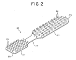
- FIG. 2 is a perspective view showing a pull tab of the slider.
- FIG. 3 is a sectional view showing the section in the back-forth direction of the slider.
- the back-forth direction of the slider is a direction parallel to the sliding direction of the slider.
- a direction in which the slider is slid to couple right and left elements is assumed to be forward while a direction in which the slider is slid to separate the right and left elements is assumed to be backward.
- the right and left direction of the slider is a direction at right angle to the back-forth direction of the slider and parallel to the fastener tape plane when the slide fastener is constructed, and the up-down direction of the slider is the same direction as the front surface to rear surface of the fastener tape when the slider fastener is constructed.
- the slider 1 for a slide fastener has a slider body 10 shown in FIG. 1 and a pull tab 20 shown in FIG. 2 .
- the slider body 10 is constituted of a molded product formed integrally by injection molding using a thermoplastic synthetic resin material such as polyamide, polypropylene, polyacetal and polybutylene terephthalate or a thermoplastic synthetic resin supplied containing an abrasion resistant reinforcing material added thereto.
- a thermoplastic synthetic resin material such as polyamide, polypropylene, polyacetal and polybutylene terephthalate or a thermoplastic synthetic resin supplied containing an abrasion resistant reinforcing material added thereto.
- this slider body 10 includes an upper blade 11, a lower blade 12 disposed in parallel to and apart from the upper blade 11, a guiding post 13 which connects the front end portions of the upper and lower blades 11, 12, a gate-shaped pull tab attaching post 14 formed integrally on the surface (top face) of the upper blade 11, and right and left flanges 15 erected from both the right and left side edges on the rear portion side of the lower blade 12 toward the upper blade 11.
- right and left shoulder mouths are formed on the front portion of the slider body 10 such that the shoulder mouths are separated by the guiding post 13, and a rear mouth is formed at the rear end of the slider body 10.
- a Y-shaped element guide passage which brings the right and left shoulder mouths and the rear mouth into communication with each other is provided between the upper and lower blades 11, 12. This element guide passage serves as a passage for allowing the right and left elements 3 to pass therethrough when the slide fastener 7 described later is constructed.
- the pull tab attaching post 14 includes right and left leg portions 14a, 14b and a bridge portion 14c.
- the right and left leg portions 14a, 14b are erected upward from both the right and left side ends of the upper blade 11 from a substantially central portion in the back-forth direction of the slider.
- the bridge portion 14c is stretched between top ends of the right and left leg portions 14a, 14b along the right and left direction of the slider.
- the pull tab attaching post 14 is formed into a symmetrical shape.
- the bridge portion 14c is disposed in parallel to the top face of the upper blade 11, and one end of the pull tab 20 is attached to the bridge portion 14c.
- the right and left leg portions 14a, 14b may be provided at positions inside of the both right and left side ends of the upper blade 11 as long as they are disposed apart from each other in a transverse direction of the slider body 10.
- the positions at which the right and left leg portions are erected can be changed easily corresponding to the width dimension or the like of the pull tab 20.
- the pull tab 20 is formed of a woven narrow thin belt-like body and bendable elastically.
- the pull tab 20 is comprised of a first pull tab main body portion 21 disposed in the back-forth direction of the slider as a grip portion, a second pull tab main body portion 22 formed shorter in the back-forth direction than the first pull tab main body portion 21, and a folding portion 23 which connects the first and second pull tab main body portions 21, 22.
- the first pull tab main body 21 is formed relatively wide in the right-left direction in order for a user to be able to grip easily.
- the first pull tab main body portion 21 has a plurality of hooks 24 on one surface (first surface 21a), thereby forming a surface fastener.
- the second pull tab main body portion 22 has the same width in the right-left direction as the first pull tab main body portion 21. Further, the second pull tab main body portion 22 has a plurality of loops 25 on the surface on the same side as a face on which the hooks 24 of the first pull tab main body portion 21 are disposed, thereby constructing a surface fastener which allows engagement/disengagement with/from the hooks 24 of the first pull tab main body portion 21.
- the folding portion 23 is formed narrower than the first and second pull tab main body portions 21, 22 and no hooks 24 or loops 25 may be disposed on both the front and rear surfaces thereof.
- the pull tab of the present invention is not limited to this example, but the first and second pull tab main body portions 21, 22 can construct the surface fastener by disposing the hooks 24 and the loops 25 mixedly on each first plane.
- the pull 20 of the first embodiment can be manufactured easily by punching out, for example, a surface fastener tape in which the hooks and the loops are disposed in parallel at predetermined intervals into a shape shown in FIG. 2 .
- the manufactured pull tab 20 is installed on the bridge portion 14c of the slider body 10 as follows.
- the second pull tab main body portion 22 of the pull tab 20 is inserted in between the upper blade 11 of the slider body 10 and the bridge portion 14c of the pull tab attaching post 14, so as to align the folding portion 23 of the pull tab 20 with a position of the bridge portion 14c of the pull tab attaching post 14.
- the second pull tab main body portion 22 is folded to the first pull tab main body portion 21 side, and the first pull tab main body portion 21 and the second pull tab main body portion 22 are engaged with each other through the hooks 24 and the loops 25. Consequently, the pull tab 20 can be easily attached to the bridge portion 14c of the slider body 10 such that the pull tab 20 is wound around the bridge portion 14c.
- the first pull tab main body portion 21 of the pull tab 20 is engaged with a partial area on the folding portion 23 side on which the second pull tab main body portion 22 is overlaid.
- the hooks 24 disposed on the first surface 21a side are exposed.
- the pull tab 20 is installed rotatably around the bridge portion 14c such that, in a state that the pull tab 20 is extended to the rear mouth side of the slider body 10 from the bridge portion 14c of the pull tab attaching post 14, the first surface 21a of the first pull tab main body portion 21 faces upward, in other words, in a state that the pull tab is extended to the shoulder mouth side of the slider body 10 from the bridge portion 14c of the pull tab attaching post 14, the first face 21a of the first pull tab main body portion 21 faces downward (to the upper blade 11).
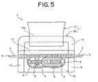
- the slide fastener 7 is constructed by placing the slider 1 of the first embodiment on the right and left elements 3 of the pair of right and left fastener stringers 2 as shown in FIGS. 4 and 5 .
- the pair of right and left fastener stringers 2 are sewed to opposing tape side edge portions of the right and left fastener tapes 4 with a core thread 6 passed through the coil-like continuous elements 3.
- the pull tab 20 of the slider 1 is formed of an elastically bendable belt-like body, and the pull tab folding portion 23 (post attaching portion) is attached rotatably in the sliding direction of the slider 1 around the pull tab attaching post 14 of the slider body 10.
- the slide fastener 7 of the first embodiment is excellent in operability of the slider 1 because the pull tab 20 of the slider 1 is easy to grip to allow the slider 1 to be operated smoothly.
- the pull tab 20 is attached directly to the pull tab attaching post 14 without use of any metal member. With this configuration, even if the pull tab 20 comes into contact with the slider body 10 made of a synthetic resin or other members, generation of contact sound can be prevented effectively, so that the slider fastener 7 from which no sound is produced can be constructed.
- the slide fastener 7 of the first embodiment can be used preferably in a seat cover or the like of a vehicle seat 31.
- the vehicle seat 31 has a seat cushion 32 and a seat back 33.
- the seat cushion 32 and the seat back 33 include a seat frame (not shown), a pad (not shown) fixed to the seat frame and having cushion performance , and seat covers 34, 35 for covering the pad.
- the seat cover 35 for use in the seat back 33 has a skin portion 35a composed of synthetic leather disposed on the outer face side and a sponge portion 35b disposed on the inner side and having cushion performance.
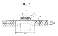
- Two parallel cut-ins 36 are formed on the seat rear face side of the seat cover 35 in the up-down direction of the seat, and the slide fasteners 7 of the first embodiment are sewed along these cut-ins 36 (see FIG. 7 ).
- the slide fastener 7 is disposed throughout the entire length of the cut-ins 36 of the seat cover rear face portion and is also extended so as to project by a predetermined length downward from a rear face portion bottom edge 37 of the seat cover 35.
- the slide fastener 7 is attached so that end stops are disposed at both top and bottom end portions of the elements 3. When the slider 1 is slid downward of the seat 31 along the elements 3, the slide fastener 7 is closed.
- the seat cover 35 is applied to the seat back 33 such that each slide fastener 7 is opened, and thereafter, the slider 1 is slid downward to close the slide fastener 7, so that the seat cover 35 can be attached easily to the seat back 33 with a good appearance.
- an extending portion 7a of the slide fastener 7 extending from the rear face portion bottom edge 37 of the seat cover 35 is folded to the back side (sponge portion 35b) of the seat cover rear face portion as shown in FIG. 8 and then inserted in between the seat cover 35 and the pad. By doing so, the extending portion 7a can be hidden invisibly from the surface of the seat 31.
- the hooks 24 are exposed from the portion on which no second pull tab main body portion 22 is overlaid of the first surface 21a of the first pull tab main body portion 21 of the pull tab 20.
- the hooks 24 of the first pull tab main body portion 21 are engaged with the sponge portion 35b of the seat cover 35 so as to fix the position of the slider 1. Consequently, even if, for example, the vehicle vibrates during its traveling, it is possible to prevent deviation of the position of the slider 1 and dangling of the slider 1 between the seat cover 35 and the pad portion.
- the position of the slider 1 is fixed to prevent the slider 1 from coming into contact with other members such as the seat frame of the seat 31. This blocks generation of the contact sound between the slider 1 and the seat frame, etc.
- the extending portion 7a of the slider fastener 7 hidden on the cover back side can be prevented from drooping from the rear face portion bottom edge 37 of the seat cover due to vibration or the like of the vehicle so that the extending portion 7a is exposed. Consequently, a good appearance can be secured stably.
- the slide fastener 7 of the first embodiment can be applied to, for example, nursing care clothes, baby clothes and infant clothes as well as the seat cover 35 of the vehicle seat 31 from viewpoints of operability of the slider 1 and preventing generation of sound.
- the position of the slider 1 can be fixed by the hooks 24 disposed on the pull tab of the slider 1. With this configuration, the slider 1 can be prevented from being operated by a child by a mistake effectively when the slide fastener is used in, for example, baby clothes or infant clothes.
- FIG. 9 is a side view schematically showing the slider for a slide fastener according to the second embodiment.
- like reference numerals are attached to components and member having the same structure as the first embodiment, and description thereof is omitted.
- a slider 41 of the second embodiment shown in FIG. 9 has a slider body 10 and a pull tab 42.
- the slider body 10 has the same configuration as the first embodiment.
- the pull tab 42 of the second embodiment is formed of a woven narrow thin belt-like body.
- the pull tab 42 has first and second pull tab main body portions 43, 44 each having the same length disposed in the back-forth direction of the slider and a folding portion 45 for connecting the pull tab main body portions 43 and 44.
- the first and second pull tab main body portions 43, 44 are formed relatively large in the width in the right and left direction in order for a user to grip easily. In the meantime, the first and second pull tab main body portions 43, 44 have no engaging elements such as hooks and loops constituting a surface fastener like the first embodiment.
- the folding portion 45 is formed narrower than the first and second pull tab main body portions 43, 44.
- the pull tab 42 of the second embodiment is attached to the bridge portion 14c of the slider body 10 in the following manner.
- the second pull tab main body portion 44 is inserted in between the upper blade 11 of the slider body 10 and the pull tab attaching post 14 so as to align the folding portion 45 of the pull tab 42 with a position of the pull tab attaching post 14. Further, the second pull tab main body portion 44 is folded to the first pull tab main body portion 43 side to be overlaid on the first pull tab main body portion 43. Thereafter, the first pull tab main body portion 43 and the second pull tab main body portion 44 are sewed together.
- the pull tab 42 is constituted of an elastically bendable belt-like body and attached such that the pull tab folding portion 45 can rotate in a sliding direction of the slider 41 around the pull tab attaching post 14 of the slider body 10.
- the slide fastener of the second embodiment allows the pull tab 42 of the slider 41 to be griped easily and the slider 41 to be operated smoothly.
- the pull tab 42 is attached directly to the pull tab attaching post 14 without use of any metallic member. Accordingly, even if the pull tab 42 comes into contact with the slider body made of a synthetic resin or other members such as a sheet frame, generation of its contact sound can be prevented effectively so as to construct a slide fastener from which any sound is not produced.
- the slide fastener of the second embodiment can be used in the seat cover 35 of the vehicle seat 31 like the first embodiment and additionally, may be applied preferably to, for example, nursing care clothes, baby clothes and infant clothes from viewpoints of operability of the slider, prevention of any sound, and excellent tactile feeling.
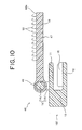
- FIG. 10 is a side view schematically showing the slider for a slide fastener of the third embodiment.
- a slider 46 shown in FIG. 10 includes a slider body 10' and a pull tab 47.
- the shape of a pull tab attaching post 14' is changed with respect to the slider body 10 of the first and second embodiments; a bridge portion 14c' stretched between right and left leg portions 14a' and 14b' is formed cylindrically; and a pull tab insertion slit is provided in a substantially central portion of the bridge portion 14c'.
- other configuration than the pull tab attaching post 14' of the slider body 10' is the same as the slider body 10 of the first and second embodiments.
- the pull tab 47 is formed by molding a synthetic resin.
- the pull tab 47 includes a pull tab main body portion 48 disposed in the back-forth direction of the slider and a post attaching portion 49 formed at one end of the pull tab main body portion 48.
- a plurality of hooks 50 are formed on a first face 48a on one side of the pull tab main body portion 48.
- the pull tab main body portion 48 is formed of a hard synthetic resin such that its width in the right-left direction is relatively large for a user to grip easily.
- the post attaching portion 49 is formed integrally with the pull tab main body portion 48 and has a donut-like circular section which allows itself to rotate around the bridge portion 14c' of the slider body 10'.
- the post attaching portion 49 of the pull tab 47 When attaching the pull tab 47 to the slider body 10', the post attaching portion 49 of the pull tab 47 is obliquely inserted into the slit provided on the bridge portion 14c of the slider body 10, so that the bridge portion 14c' is inserted into a hollow portion of the post attaching portion 49. Further, by rotating the pull tab 47 while moving it in the width direction of the slider body 10', the bridge portion 14c' is fitted to the hollow portion in the post attaching portion 49 from both the right and left sides. By doing so, the pull tab 47 is rotatably attached to the slider body 10'.
- the method of attaching the pull tab 47 to the slider body 10' is not limited to any particular one.
- the pull tab 47 is constructed separately of a first member in which a portion having a C-shaped section constituting part of the post attaching portion 49 and the pull tab main body portion 48 are formed integrally, and a second member having a circular section constituting the remaining portion of the post attaching portion 49. Then, both end faces of the second member are fitted to both the end faces of the C-shaped portion with the bridge portion 14c' of the slider body 10 inserted into the C-shaped portion of the first member. Subsequently, the first member and the second member are fused together or bonded together through their contact portions, so as to achieve attachment of the pull tab 47 to the slider body 10.
- the slider 46 obtained in this way can suppress generation of any contact sound when the pull tab 47 comes into contact with the slider body made of a synthetic resin.
- the slide fastener constructed with this slider 46 may be used preferably in the seat cover 35 of the vehicle seat 31 like the first embodiment.
- the slide fastener 46 of the third embodiment may be used in the seat cover 35 of the vehicle seat 31.
- the hooks 50 of the pull tab main body portion 48 can be engaged easily with the sponge portion 35b of the seat cover 35. This is because the first face 48a of the pull tab main body portion 48 has a plurality of hooks 50.
- substantially the same effect as the first embodiment can be obtained, for example, deviation of the position of the slider 46 or dangling of the slider 46 can be prevented even if, for example, the vehicle is vibrated during its traveling.
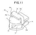
- FIG. 11 is a perspective view showing a slider body of the slider
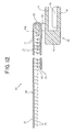
- FIG. 12 is a longitudinal sectional view showing a section of the slider.
- the slider 51 of the fourth embodiment includes a slider body 52 and a pull tab 20.
- the slider body 52 includes upper and lower blades 11, 12, a guiding post 13 which connects the front end portions of the upper and lower blades 11, 12, a gate-shaped pull tab attaching post 53 formed integrally on the top face of the upper blade 11, and right and left flanges 15 disposed on both the right and left side edges of the lower blade 12.
- the pull tab attaching post 53 includes right and left leg portions 53a, 53b erected upward from both the right and left side edge portions of the upper blade 11, a bridge portion 53c which is stretched between the top end portions of the right and left leg portions 53a and 53b along the right-left direction of the slider, and a tongue piece 53d projected forward in parallel to the top face of the upper blade 11 from the bridge portion 53c.
- the pull tab 20 of the fourth embodiment is the same as the first embodiment, and includes first and second pull tab main body portions 21, 22 and a folding portion 23 for connecting the first and second pull tab main body portions 21, 22.
- the first pull tab main body portion 21 of the pull tab has a plurality of hooks 24 on a first surface 21a thereof.
- the second pull tab main body portion 22 has a plurality of loops 25 capable of engaging the hooks 24 of the first pull tab main body portion 21 on a first surface 22a thereof.
- This pull tab 20 is attached such that it is wound around the bridge portion 53c and the tongue piece 53d of the pull tab attaching post 53 by inserting the second pull tab main body portion 22 between the upper blade 11 of the slider body 52, the bridge portion 53 and the tongue piece 53d of the pull tab attaching post 53, and then folding back the second pull tab main body portion 22 to the first pull tab main body portion 21 side to engage the hooks 24 with the loops 25.
- the pull tab 20 is attached such that the extending direction of the pull tab 20 from the pull tab attaching post 53 is oriented forward of the slider. Consequently, the extending direction of the pull tab 20 is limited to the forward direction by the tongue piece 53d of the pull tab attaching post 53, and the pull tab 20 is blocked from rotating around the bridge portion 53c and the tongue piece 53d. This enables the pull tab 20 to be blocked from dangling freely.
- the pull tab 20 of the slider 51 is bendable elastically. With this configuration, the pull tab 20 can be bent easily by gripping with the fingers when the slider 51 is operated, although the pull tab 20 cannot be rotated around the pull tab attaching post 53.
- the slider 51 when the slide fastener is closed, the slider 51 can be slid easily in its closing direction by gripping the pull tab 20 of the slider 51 and pulling it in an extension direction of the pull tab 20. Further, when the slide fastener is opened to the right and left sides, the slider 51 can be slid easily in its opening direction by gripping the pull tab 20 of the slider 51 and pulling it in an opposite direction (backward) to the extending direction while bending it (see two-dot and dash line in FIG. 12 ). When the fingers are released from the pull tab 20 after the slider 51 is operated, the pull tab 20 can be reoriented forward of the slider with respect to the bridge portion 53c by the tongue piece 53d provided on the pull tab attaching post 53 and the elastic restoration of the pull tab 20.
- the pull tab 20 can be oriented forward of the slider securely with respect to the bridge portion 53c when the slide fastener is closed to cause the extending portion of the slide fastener to be hidden by the back side of the seat cover rear face portion.
- the hooks 24 exposed on the first face 21a of the first pull tab main body portion 21 of the pull tab 20 can be securely engaged with the sponge portion 35b of the seat cover 35, and the position of the slider can be fixedmore securely than the first embodiment.
- the tongue piece 53d may be projected backward in parallel to the top face of the upper blade 11 from the bridge portion 53c.
- FIG. 13 is a longitudinal sectional view showing the section of the slider.
- a slider 61 of the fifth embodiment includes a slider body 62 and a pull tab 20.
- the slider body 62 includes upper and lower blades 11, 12, a guiding post 13 which connects the front end portions of the upper and lower blades 11, 12, a gate-shaped pull tab attaching post 63 formed integrally on the top face of the upper blade 11, and right and left flanges 15 disposed on both the right and left side edges of the lower blade 12.
- the pull tab attaching post 63 includes right and left leg portions erected upward from both right and left side edge portions of the upper blade 11 and a bridge portion 63c which is stretched between the top end portions of the right and left leg portions.
- the bridge portion 63c is formed in a larger thickness than the slider 1 of the first embodiment.
- the pull tab 20 of the fifth embodiment is the same as the first and fourth embodiments and includes first and second pull tab main body portions 21, 22 and a folding portion 23.
- the pull tab 20 of the fifth embodiment is wound around the bridge portion 63c by inserting the second pull tab main body portion 22 in between the upper blade 11 of the slider body 62 and the bridge portion 63c and folding the second pull tab main body portion 22 to the first pull tab main body portion 21 side so that the second pull tab main body portion 22 is engaged with the first pull tab main body portion 21. Thereafter, with the pull tab 20 held such that it is extended forward of the slider from the bridge portion 63c, the folding portion 23 of the pull tab 20 is fixed to the bridge portion 63c by ultrasonic welding or the like.
- the extending direction of the pull tab 20 is limited to forward and the folding portion 23 of the pull tab 20 is blocked from rotating around the bridge portion 63c.
- the pull tab 20 can be prevented from dangling freely around the pull tab attaching post 63.
- the pull tab 20 of the slider 61 is bendable elastically.
- the pull tab 20 can be bent by gripping with the fingers when operating the slider 61 like the fourth embodiment, and when the slide fastener is closed or opened, the sliding operation of the slider 61 can be carried out easily.
- the pull tab 20 can be oriented forward of the slider with respect to the bridge portion 63c, thereby obtaining the same effect as the slide fastener of the fourth embodiment.
Landscapes
- Slide Fasteners (AREA)
- Surface Treatment Of Glass (AREA)
- Manufacturing Of Magnetic Record Carriers (AREA)
Abstract
The present invention provides a slider for a slide fastener, capable of preventing any sound from being generated by reducing contact sound from a slider body or a pull tab without affecting operability of the slide fastener. There is provided a slider (1,41,46,51,61) for a slide fastener including a slider body (10,10',52,62), being characterized by further including: a gate-shaped pull tab attaching post (14,14',53,63) having right and left leg portions (14a,14b,14a',14b',53a,53b) erected from the upper blade (11) and apart from each other in a transverse direction of the slider body (10,10';52,62) and a bridge portion (14c,14c',53c,63c) stretched between the top end portions of the right and left leg portions (14a,14b,14a',14b',53a,53b), the pull tab attaching post being formed integrally with the slider body (10,10',52,62); and a pull tab (20,42,47), one end of which is attached to the bridge portion (14c,14c',53c,63c), the pull tab extending from the bridge portion (14c,14c',53c,63c).
Description
- The present invention relates to a slider for a slide fastener, capable of reducing sound generated by a contact between a slider body and a pull tab.
- Conventionally, a slide fastener is attached to an opening in order to easily open/close the opening in clothes, bag or the like. Generally, the slide fastener is constructed by arranging a plurality of fastener elements on each of element attaching edge portions opposing each other of right and left fastener tapes so as to form a pair of right and left fastener stringers, and then placing a slider on the right and left element rows composed of the plurality of fastener elements disposed on the right and left fastener stringers.
- A slider has a slider body to be placed on the element rows and a pull tab attached to the slider body. The slider body is often made of metal and generally, includes upper and lower blades, a connecting post for connecting the upper and lower blades at a front end portion of the slider, right and left flanges formed on right and left side edges of the upper blade and/or the lower blade, and a pull tab attaching post erected on the surface (top surface) of the upper blade along the back-forth direction of the slider.
- Right and left shoulder mouths are formed on the front end side of the slider body such that they are divided by the connecting post while a rear mouth is formed at a rear end of the slider body. Further, a Y-shaped element guide passage which brings the right and left shoulder mouths and the rear mouth in communication with each other is disposed between the upper and lower blades. The pull tab has a connecting portion for connecting one end thereof to the pull tab attaching post provided on the slider body and a grip portion disposed on the other end of the connecting portion.
- An example of the slide fastener having such a configuration is described in European Patent No.
761117 slide fastener 71 described in thepatent document 1, as shown inFIG. 14 , aslider 74 is placed on element rows 73 of the pair of right andleft fastener stringers 72. Theslider 74 in thispatent document 1 includes aslider body 75 and apull tab 76. Theslider body 75 includes an upper blade, a lower blade, a connecting post, right and left flanges, and an inverted U-shaped pulltab attaching post 75a. - The
pull tab 76 has a connectingbody 77 and agrip portion 78. The connectingportion 77 includes a first attachingportion 77a which is constituted of a hole portion formed at one end portion thereof and a second attachingportion 77b which is composed of a ring-like limb disposed at the other end portion thereof. In this case, the connectingbody 77 is installed onto theslider body 75 by inserting the first attachingportion 77a into the inverted U-shaped pulltab attaching post 75a disposed on theslider body 75 in a cantilevered state such that the attachingpost 75a is hooked on theslider body 75, and thereafter deforming the pulltab attaching post 75a plastically so that the connectingbody 77 does not slip out of the pulltab attaching post 75a. - On the other hand, the
grip portion 78 has a first main body portion (surface half portion) 78a, a second main body portion (rear surface half portion) 78b, and aneck portion 78c for connecting the first and secondmain body portions main body portion 78a of thegrip portion 78 has a plurality ofloops 78d which constitute a surface fastener, and the first surface (inner side face) of the secondmain body portion 78b has a plurality ofhooks 78e which constitute a surface fastener. - The
grip portion 78 having the plurality ofloops 78d and the plurality ofhooks 78e is installed onto the connectingbody 77 by overlapping the firstmain body portion 78a and the secondmain body portion 78b after the firstmain body portion 78a or the secondmain body portion 78e is inserted into the second attaching portion (limb) 77b of the connectingbody 77 so as to engage thehooks 78e of the secondmain body portion 78b with theloops 78d of the firstmain body portion 78a. - The
slide fastener 71 of thepatent document 1 can be manufactured at a lower cost than, for example, a slide fastener using a rivet for attaching thegrip portion 78. Thegrip portion 78 can be formed into a desired shape by, for example, cutting out the surface fastener into a predetermined shape. Thus, thegrip portion 78 can have ample variations, and further various patterns or logo marks, etc. can be provided on the front surface or the rear surface (second surface of the first main body portion and the second main body portion) of thegrip portion 78. - Generally, the slide fasteners have been used at an opening of clothes or bags, etc., and in recent years, they have been often used in seat covers of passenger seats of vehicles or the like. For example, Japanese Patent No.
3380150 - A
seat 81 described in thispatent document 2 is comprised of aseat cushion 82 and aseat back 83 as shown inFIG. 16 . Thesecomponents skins - According to the
patent document 2, theskin 87 of theseat back 83 has acutout 88 extending upward from the bottom edge of the seat rear face, and a skinrear face portion 87a is so formed to be separable to its right and left sections with thecutout 88 interposed therebetween. Aslide fastener 89 is sewed along thecutout 88 formed on the skinrear face portion 87a. When theslider 92 of theslide fastener 89 is slid downward, right andleft elements 91 are coupled with each other so as to close thecutout 88. - One end portion of the
slide fastener 89 is extended downward longer than abottom edge 87b of the skinrear face portion 87a. One of the right and left fastener stringers is sewed to theskin 87 so that the stringer is hidden invisibly from outside by folding theskin 87 extending from theskin bottom edge 87b to the back side. - In the
seat 81 described in thepatent document 2, theskin 87 is applied to the pad of the seat back 83 in a state that the skinrear face portion 87a is separated to the right and left sections by opening theslide fastener 89, and thereafter, theslider 92 is slid to close theslide fastener 89, so that theskin 87 can be fitted to the pad in a good appearance. - Particularly in the
seat 81 of thepatent document 2, one of the fastener stringers of theslide fastener 89 is sewed such that the portion extending downward form theskin bottom edge 87b is hidden on the skin back side. Thus, when theslide fastener 89 is closed, the extending portion of the other fastener stringer is folded to the skin back side and hidden there. Consequently, when theslide fastener 89 is closed, the end portion on the extending portion side of theslide fastener 89 is held at a predetermined position on the skin back side. - For the reason, in the
skin 87 applied to the pad of theseat 81, the extending portion of theslide fastener 89 is difficult to peel from the skin back side even if, for example, the fingers of a passenger seated on theseat 81 are hooked on theslide fastener 89 by a mistake. Thus, the closing state of theslide fastener 89 can be maintained in a stable state. - In the conventional slide fastener of the
patent document 1, the grip portion of the slider is constructed of a belt-like body such as fabric having a surface fastener to facilitate gripping of the pull tab and is also disposed such that the front and rear faces of the grip portion are oriented in a lateral direction with respect to the sliding direction of the slider. The connecting portion of the slider is supported on the slider body rotatably along the sliding direction of the slider with respect to the first attaching portion on the slider body side so that a user can slide the slider smoothly along the element rows by gripping the grip portion. Further, this connecting portion is formed of a metal member which hardly cracks in order to securely connect the slider body with the pull tab in a long period. - Although in the conventional slide fastener, the pull tab of the slider is attached considering the operability and the like of the slider, there is such a problem that when the slider is not operated, the metal slider body comes into contact with the connecting portion of the pull tab so as to produce a metallic clank offensive to the ears. If the slide fastener is used in, for example, a seat cover of vehicle seats as disclosed in the
patent document 2, the slider body frequently comes into contact with the pull tab due to vibration during traveling of the vehicle and further when the slider swings, the slider body and the pull tab come into contact with other members such as a seat frame, thereby producing contact sound. - Generation of such contact sound due to a contact between the slider body and the pull tab or a contact thereof with other members can be reduced to some extent by forming the slider body and the connecting portion of the pull tab with a synthetic resin molded product. However, it is demanded to prevent the generation of the contact sound effectively in order to improve the quality of the slide fastener further.
- Preventing the generation of the contact sound in the slider body and the pull tab without reduction of the operability of the slider has been demanded on a slide fastener for use in baby clothes, infant clothes, nursing care clothes and the like in which the contact sound is offensive to the ears as well as the slider fastener for use in the seat cover of the above-mentioned vehicle seats.
- When the
slide fastener 89 is used in the skin (seat cover) 87 or the like of thevehicle seat 81 as described in thepatent document 2, theslider 92 may be hidden on the skin back side by closing theslide fastener 89. Even in such a case, if the portion hidden by the slide fastener 89 (portion extending form theskin bottom edge 87b) is short, the pull tab of theslider 89 rotates around the slider body, so that part of the pull tab sometimes might project out so that the part of the pull tab droops from thebottom edge 87b. If the pull tab of theslider 89 is exposed, the appearance of the slider is bad and the pull tab is easily hooked by other members, thereby causing a fear that the slider may be operated by a mistake. - The present invention has been achieved in views of the above-mentioned conventional problems, and an object of the invention is to provide a slider for a slide fastener capable of preventing generation of sound even when, for example, it is used in a seat cover of a vehicle seat by reducing contact sound generated from a slider body or a pull tab. Another object of the present invention is to provide a slider for a slide fastener which can be securely hidden on the back side of a seat cover when a slide fastener is used in the seat cover or the like.
- To achieve the above-described object, the present invention provides a slider for a slide fastener in which an upper blade and a lower blade are connected by a guiding post at a front end portion on a shoulder mouth side while a slider body having a rear mouth is provided at the rear end, being characterized by further including: a gate-shaped pull tab attaching post having right and left leg portions erected from the upper blade and apart from each other in a transverse direction of the slider body and a bridge portion stretched between the top end portions of the right and left leg portions, the pull tab attaching post being formed integrally with the slider body; and a pull tab, one end of which is attached to the bridge portion, the pull tab extending from the bridge portion.
- In the slider for a slide fastener of the present invention, the slider body is preferably composed of a synthetic resin.
- Preferably, the slider of the present invention further includes rotation blocking means for blocking a post attaching portion for the pull tab to be attached to the bridge portion from rotating around the bridge portion. In this case, it is preferable that the rotation blocking means is constituted of a tongue piece projecting from the bridge portion. The rotation blocking means may be constructed by fixing the pull tab to the bridge portion.
- In the slider of the present invention, the pull tab is preferably bendable elastically. Alternatively, the pull tab may be composed of a hard synthetic resin.
- It is preferable that the pull tab is formed of a narrow thin piece having first and second pull tab main body portions disposed in the back-forth direction of the slider and a folding portion which connects the first and second pull tab main body portions, and that the first and second pull tab main body portions have surface fastener engaging elements disposed on at least part of each of first surfaces which oppose each other when the pull tab is folded at the folding portion.
- In this case, preferably, the first pull tab main body portion is formed longer than the second pull tabmain body portion, and male engaging elements of a surface fastener are disposed in area of the first surface of the first pull tab main body portion other than a portion thereof the second pull tab main body portion overlaps when the first and second pull tab main body portions are engaged with each other. Particularly, it is preferable that the pull tab is attached such that the first surface of the first pull tab main body portion faces downward when the pull tab is extended to the shoulder mouth side of the slider body from the bridge portion.
- The slider for a slide fastener of the present invention includes a slider body, a gate-shaped pull tab attaching post formed integrally on an upper blade of the slider body in a symmetrical configuration, and a pull tab made of a belt-like body one end of which is attached to a bridge portion of the pull tab attaching post. The pull tab attaching post includes right and left leg portions erected from the upper blade and apart from each other in the transverse direction of the slider body, and the bridge portion which is stretched between the top end portions of the right and left leg portions.
- In the slider of the present invention having such a configuration, the pull tab is extended in the back-forth direction of the slider from the bridge portion of the gate-shaped pull tab attaching post disposed in the right-left direction, and the front and rear faces of the pull tab are oriented in a lateral direction with respect to the sliding direction of the slider. Consequently, the pull tab of the slider is easy to grip and the slider can be operated easily, thereby securing an excellent operability.
- In the slider of the present invention, one end of the pull tab is attached directly to the pull tab attaching post without use of any metallic connecting member like a conventional example. Thus, generation of contact sound can be prevented effectively even if the pull tab comes into contact with the slider body or other member. Particularly, if the slider body is made of a synthetic resin or the pull tab is made of a belt-like body in the present invention, generation of the sound due to a contact between the slider body and the pull tab can be prevented securely. Even if the slider body comes into contact with other members, generation of the contact sound can be prevented effectively.
- In the slider of the present invention, the post attaching portion for the pull tab to be attached to the bridge portion has the rotation blocking means for blocking the rotation around the bridge portion. Consequently, the direction of the pull tab when the slider is not operated can be limited to a certain direction. Thus, the pull tab can be prevented from dangling and the pull tab can be prevented from coming into contact with the slider body or other members.
- By limiting the direction of the pull tab to a certain direction, the direction of the pull tab when the slide fastener is closed can be specified to a predetermined one, for example, if the slide fastener is used in a seat cover of a vehicle seat. Consequently, when the slider is hidden on the back side of the seat cover, the pull tab does not jump out from the back side of the seat cover even if the slider receives a vibration or the like of the vehicle, whereby the pull tab can be hidden securely. Accordingly, the closing state of the slider fastener can be maintained stably.
- In this case, the rotation blocking means can be easily constructed of the tongue piece projecting from the bridge portion, or can be easily constructed by fixing the pull tab to the bridge portion. If the tongue piece is formed as the rotation blocking means, the direction of the pull tab when the slider is not operated can be oriented in its predetermined direction easily by projecting the tongue piece in a predetermined direction from the bridge portion, for example, to the shoulder mouth side or rear mouth side in parallel to the upper blade.
- In the slider of the present invention, the pull tab is constructed to be bendable elastically. Consequently, the direction of the pull tab can be oriented easily to the sliding direction of the slider when the slider is slid along element rows, so that the slider can be operated smoothly. If the slider has the rotation blocking means, the pull tab can be oriented to a predetermined direction which is limited by the rotation blocking means when the pull tab is released from the fingers. The pull tab may be composed of a hard synthetic resin. Consequently, the pull tab can be constructed to be easy to grip, whereby the sliding operation of the slider can be carried out easily.
- The pull tab of the slider of the present invention is constructed of a narrow thin piece comprised of the first and second pull tab main body portions disposed in the back-forth direction of the slider and the folding portion which connects these. Further, the first and second pull tab main body portions have engaging elements of a surface fastener which can engage each other on at least part of each of the first faces. As a result, the pull tab can be manufactured at a low cost and the pull tab can be easily attached to the pull tab attaching post.
- In this case, the first pull tab main body portion in the present invention is formed longer than the second pull tab main body portion, and male engaging elements of a surface fastener are disposed in area of the first surface of the first pull tab main body portion other than a portion thereof the second pull tab main body portion overlaps when the first and second pull tab main body portions are engaged with each other. As a result, for example, in case where the slide fastener is used in the seat cover of the vehicle seat and the slider is hidden on the back side of the seat cover, the slider can be fixed at a predetermined position by engaging the male engaging elements disposed on the first face of the first pull tab main body portion with the back side of the seat cover. Therefore, the slider can be prevented from dangling freely, so that the slider can be prevented from coming into contact with the seat frame or the like of the vehicle seat, thereby blocking generation of a contact sound securely. Even if the slider receives avibration or the like of the vehicle, it never slides freely along the element rows, whereby the closing state of the slide fastener can be maintained stably.
- Particularly when the pull tab is extended to the shoulder mouth of the slider body from the bridge portion of the pull tab attaching post, the pull tab is preferably attached such that the first face of the first pull tab main body portion faces downward (upper blade side). Consequently, when the slider is hidden on the back side of the seat cover, the male engaging elements of the first pull tab main body portion can be easily engaged with the seat cover back side, whereby the slider can be fixed at a predetermined position securely.
-
-
FIG. 1 is a perspective view showing a slider body of a slider for a slide fastener according to a first embodiment of the present invention; -
FIG. 2 is a perspective view showing a pull tab of the slider; -
FIG. 3 is a sectional view showing the section in the back-forth direction of the slider; -
FIG. 4 is a front view showing a slide fastener constructed with the slider; -
FIG. 5 is a rear view of the slider when the slider of the slide fastener is seen from the rear mouth side of the slider; -
FIG. 6 is a perspective view showing a vehicle seat; -
FIG. 7 is a sectional view showing a section of part of the seat cover to be attached to the vehicle seat; -
FIG. 8 is a sectional view showing a state in which an extending portion of the slide fastener is hidden; -
FIG. 9 is a schematic view schematically showing a slider for a slide fastener according to a second embodiment of the present invention; -
FIG. 10 is a side view schematically showing a slider for a slide fastener according to a third embodiment of the present invention; -
FIG. 11 is a perspective view schematically showing a slider for a slide fastener according to a fourth embodiment of the present invention; -
FIG. 12 is a longitudinal sectional view showing the section of the slider body; -
FIG. 13 is a longitudinal sectional view schematically showing a slider for a slide fastener according to a fifth embodiment of the present invention; -
FIG. 14 is a front view showing a conventional slide fastener; -
FIG. 15 is an explanatory view for explaining a pull tab for use in the slider fastener; and -
FIG. 16 is a perspective view showing a vehicle seat using a conventional slide fastener. - Hereinafter, preferred embodiments of the present invention will be described in detail with reference to the accompanying drawings.
-
FIGS. 1 to 3 show a slider for a slide fastener according to a first embodiment of the present invention.FIG. 1 is a perspective view showing a slider body of the slider, andFIG. 2 is a perspective view showing a pull tab of the slider.FIG. 3 is a sectional view showing the section in the back-forth direction of the slider. - In the description of each embodiment, the back-forth direction of the slider is a direction parallel to the sliding direction of the slider. In the slide fastener, a direction in which the slider is slid to couple right and left elements is assumed to be forward while a direction in which the slider is slid to separate the right and left elements is assumed to be backward. The right and left direction of the slider is a direction at right angle to the back-forth direction of the slider and parallel to the fastener tape plane when the slide fastener is constructed, and the up-down direction of the slider is the same direction as the front surface to rear surface of the fastener tape when the slider fastener is constructed.
- The
slider 1 for a slide fastener according to the first embodiment has aslider body 10 shown inFIG. 1 and apull tab 20 shown inFIG. 2 . - The
slider body 10 is constituted of a molded product formed integrally by injection molding using a thermoplastic synthetic resin material such as polyamide, polypropylene, polyacetal and polybutylene terephthalate or a thermoplastic synthetic resin supplied containing an abrasion resistant reinforcing material added thereto. - As shown in
FIG. 1 , thisslider body 10 includes anupper blade 11, alower blade 12 disposed in parallel to and apart from theupper blade 11, a guidingpost 13 which connects the front end portions of the upper andlower blades tab attaching post 14 formed integrally on the surface (top face) of theupper blade 11, and right and leftflanges 15 erected from both the right and left side edges on the rear portion side of thelower blade 12 toward theupper blade 11. - Consequently, right and left shoulder mouths are formed on the front portion of the
slider body 10 such that the shoulder mouths are separated by the guidingpost 13, and a rear mouth is formed at the rear end of theslider body 10. A Y-shaped element guide passage which brings the right and left shoulder mouths and the rear mouth into communication with each other is provided between the upper andlower blades elements 3 to pass therethrough when theslide fastener 7 described later is constructed. - The pull
tab attaching post 14 includes right andleft leg portions bridge portion 14c. The right andleft leg portions upper blade 11 from a substantially central portion in the back-forth direction of the slider. Thebridge portion 14c is stretched between top ends of the right andleft leg portions tab attaching post 14 is formed into a symmetrical shape. Thebridge portion 14c is disposed in parallel to the top face of theupper blade 11, and one end of thepull tab 20 is attached to thebridge portion 14c. In the present invention, the right andleft leg portions upper blade 11 as long as they are disposed apart from each other in a transverse direction of theslider body 10. The positions at which the right and left leg portions are erected can be changed easily corresponding to the width dimension or the like of thepull tab 20. - The
pull tab 20 is formed of a woven narrow thin belt-like body and bendable elastically. Thepull tab 20 is comprised of a first pull tabmain body portion 21 disposed in the back-forth direction of the slider as a grip portion, a second pull tabmain body portion 22 formed shorter in the back-forth direction than the first pull tabmain body portion 21, and afolding portion 23 which connects the first and second pull tabmain body portions - The first pull tab
main body 21 is formed relatively wide in the right-left direction in order for a user to be able to grip easily. The first pull tabmain body portion 21 has a plurality ofhooks 24 on one surface (first surface 21a), thereby forming a surface fastener. - The second pull tab
main body portion 22 has the same width in the right-left direction as the first pull tabmain body portion 21. Further, the second pull tabmain body portion 22 has a plurality ofloops 25 on the surface on the same side as a face on which thehooks 24 of the first pull tabmain body portion 21 are disposed, thereby constructing a surface fastener which allows engagement/disengagement with/from thehooks 24 of the first pull tabmain body portion 21. - The folding
portion 23 is formed narrower than the first and second pull tabmain body portions hooks 24 orloops 25 may be disposed on both the front and rear surfaces thereof. - In the meantime, the pull tab of the present invention is not limited to this example, but the first and second pull tab
main body portions hooks 24 and theloops 25 mixedly on each first plane. - The
pull 20 of the first embodiment can be manufactured easily by punching out, for example, a surface fastener tape in which the hooks and the loops are disposed in parallel at predetermined intervals into a shape shown inFIG. 2 . The manufacturedpull tab 20 is installed on thebridge portion 14c of theslider body 10 as follows. - First, the second pull tab
main body portion 22 of thepull tab 20 is inserted in between theupper blade 11 of theslider body 10 and thebridge portion 14c of the pulltab attaching post 14, so as to align thefolding portion 23 of thepull tab 20 with a position of thebridge portion 14c of the pulltab attaching post 14. Thereafter, the second pull tabmain body portion 22 is folded to the first pull tabmain body portion 21 side, and the first pull tabmain body portion 21 and the second pull tabmain body portion 22 are engaged with each other through thehooks 24 and theloops 25. Consequently, thepull tab 20 can be easily attached to thebridge portion 14c of theslider body 10 such that thepull tab 20 is wound around thebridge portion 14c. - In this case, as shown in
FIG. 3 , the first pull tabmain body portion 21 of thepull tab 20 is engaged with a partial area on thefolding portion 23 side on which the second pull tabmain body portion 22 is overlaid. Thus, in a portion on which no second pull tabmain body portion 22 is overlaid, thehooks 24 disposed on thefirst surface 21a side are exposed. - In the first embodiment, the
pull tab 20 is installed rotatably around thebridge portion 14c such that, in a state that thepull tab 20 is extended to the rear mouth side of theslider body 10 from thebridge portion 14c of the pulltab attaching post 14, thefirst surface 21a of the first pull tabmain body portion 21 faces upward, in other words, in a state that the pull tab is extended to the shoulder mouth side of theslider body 10 from thebridge portion 14c of the pulltab attaching post 14, thefirst face 21a of the first pull tabmain body portion 21 faces downward (to the upper blade 11). - The
slide fastener 7 is constructed by placing theslider 1 of the first embodiment on the right and leftelements 3 of the pair of right and leftfastener stringers 2 as shown inFIGS. 4 and5 . In this case, the pair of right and leftfastener stringers 2 are sewed to opposing tape side edge portions of the right and leftfastener tapes 4 with acore thread 6 passed through the coil-likecontinuous elements 3. - In the
slide fastener 7 having theslider 1 of the first embodiment, thepull tab 20 of theslider 1 is formed of an elastically bendable belt-like body, and the pull tab folding portion 23 (post attaching portion) is attached rotatably in the sliding direction of theslider 1 around the pulltab attaching post 14 of theslider body 10. Thus, theslide fastener 7 of the first embodiment is excellent in operability of theslider 1 because thepull tab 20 of theslider 1 is easy to grip to allow theslider 1 to be operated smoothly. - Further, in the
slider 1 of the first embodiment, thepull tab 20 is attached directly to the pulltab attaching post 14 without use of any metal member. With this configuration, even if thepull tab 20 comes into contact with theslider body 10 made of a synthetic resin or other members, generation of contact sound can be prevented effectively, so that theslider fastener 7 from which no sound is produced can be constructed. - As shown in
FIGS. 6 and7 , theslide fastener 7 of the first embodiment can be used preferably in a seat cover or the like of avehicle seat 31. In this case, thevehicle seat 31 has aseat cushion 32 and a seat back 33. Theseat cushion 32 and the seat back 33 include a seat frame (not shown), a pad (not shown) fixed to the seat frame and having cushion performance , and seat covers 34, 35 for covering the pad. - The
seat cover 35 for use in the seat back 33 has askin portion 35a composed of synthetic leather disposed on the outer face side and asponge portion 35b disposed on the inner side and having cushion performance. Two parallel cut-ins 36 are formed on the seat rear face side of theseat cover 35 in the up-down direction of the seat, and theslide fasteners 7 of the first embodiment are sewed along these cut-ins 36 (seeFIG. 7 ). - In this case, the
slide fastener 7 is disposed throughout the entire length of the cut-ins 36 of the seat cover rear face portion and is also extended so as to project by a predetermined length downward from a rear faceportion bottom edge 37 of theseat cover 35. Theslide fastener 7 is attached so that end stops are disposed at both top and bottom end portions of theelements 3. When theslider 1 is slid downward of theseat 31 along theelements 3, theslide fastener 7 is closed. - When the
slide fastener 7 of the first embodiment is used in theseat cover 35 of thevehicle seat 31, theseat cover 35 is applied to the seat back 33 such that eachslide fastener 7 is opened, and thereafter, theslider 1 is slid downward to close theslide fastener 7, so that theseat cover 35 can be attached easily to the seat back 33 with a good appearance. - Thereafter, an extending
portion 7a of theslide fastener 7 extending from the rear faceportion bottom edge 37 of theseat cover 35 is folded to the back side (sponge portion 35b) of the seat cover rear face portion as shown inFIG. 8 and then inserted in between theseat cover 35 and the pad. By doing so, the extendingportion 7a can be hidden invisibly from the surface of theseat 31. - Particularly in the
slider 1 of the first embodiment, thehooks 24 are exposed from the portion on which no second pull tabmain body portion 22 is overlaid of thefirst surface 21a of the first pull tabmain body portion 21 of thepull tab 20. Thus, when the extendingportion 7a of theslide fastener 7 is hidden on the cover back side, thehooks 24 of the first pull tabmain body portion 21 are engaged with thesponge portion 35b of theseat cover 35 so as to fix the position of theslider 1. Consequently, even if, for example, the vehicle vibrates during its traveling, it is possible to prevent deviation of the position of theslider 1 and dangling of theslider 1 between theseat cover 35 and the pad portion. - In addition to an effect of preventing generation of the contact sound between the
pull tab 20 and theslider body 10, etc. , the position of theslider 1 is fixed to prevent theslider 1 from coming into contact with other members such as the seat frame of theseat 31. This blocks generation of the contact sound between theslider 1 and the seat frame, etc. - Further, because the position of the
slider 1 is fixed, the extendingportion 7a of theslider fastener 7 hidden on the cover back side can be prevented from drooping from the rear faceportion bottom edge 37 of the seat cover due to vibration or the like of the vehicle so that the extendingportion 7a is exposed. Consequently, a good appearance can be secured stably. - In the meantime, the
slide fastener 7 of the first embodiment can be applied to, for example, nursing care clothes, baby clothes and infant clothes as well as theseat cover 35 of thevehicle seat 31 from viewpoints of operability of theslider 1 and preventing generation of sound. Particularly theslide fastener 7 of the first embodiment, the position of theslider 1 can be fixed by thehooks 24 disposed on the pull tab of theslider 1. With this configuration, theslider 1 can be prevented from being operated by a child by a mistake effectively when the slide fastener is used in, for example, baby clothes or infant clothes. - Next, a slider for a slide fastener according to a second embodiment of the present invention will be described.
FIG. 9 is a side view schematically showing the slider for a slide fastener according to the second embodiment. In the second embodiment and third to fifth embodiments described later, like reference numerals are attached to components and member having the same structure as the first embodiment, and description thereof is omitted. - A
slider 41 of the second embodiment shown inFIG. 9 has aslider body 10 and apull tab 42. Theslider body 10 has the same configuration as the first embodiment. On the other hand, thepull tab 42 of the second embodiment is formed of a woven narrow thin belt-like body. Thepull tab 42 has first and second pull tabmain body portions folding portion 45 for connecting the pull tabmain body portions - The first and second pull tab
main body portions main body portions portion 45 is formed narrower than the first and second pull tabmain body portions - The
pull tab 42 of the second embodiment is attached to thebridge portion 14c of theslider body 10 in the following manner. The second pull tabmain body portion 44 is inserted in between theupper blade 11 of theslider body 10 and the pulltab attaching post 14 so as to align thefolding portion 45 of thepull tab 42 with a position of the pulltab attaching post 14. Further, the second pull tabmain body portion 44 is folded to the first pull tabmain body portion 43 side to be overlaid on the first pull tabmain body portion 43. Thereafter, the first pull tabmain body portion 43 and the second pull tabmain body portion 44 are sewed together. - In the slide fastener constructed using the
slider 41 of the second embodiment, thepull tab 42 is constituted of an elastically bendable belt-like body and attached such that the pulltab folding portion 45 can rotate in a sliding direction of theslider 41 around the pulltab attaching post 14 of theslider body 10. Thus, the slide fastener of the second embodiment allows thepull tab 42 of theslider 41 to be griped easily and theslider 41 to be operated smoothly. - In the
slider 41 of the second embodiment, thepull tab 42 is attached directly to the pulltab attaching post 14 without use of any metallic member. Accordingly, even if thepull tab 42 comes into contact with the slider body made of a synthetic resin or other members such as a sheet frame, generation of its contact sound can be prevented effectively so as to construct a slide fastener from which any sound is not produced. - The slide fastener of the second embodiment can be used in the
seat cover 35 of thevehicle seat 31 like the first embodiment and additionally, may be applied preferably to, for example, nursing care clothes, baby clothes and infant clothes from viewpoints of operability of the slider, prevention of any sound, and excellent tactile feeling. - Subsequently, a slider for a slide fastener according to a third embodiment of the present invention will be described.
FIG. 10 is a side view schematically showing the slider for a slide fastener of the third embodiment. - A
slider 46 shown inFIG. 10 includes a slider body 10' and apull tab 47. In this slider body 10' , the shape of a pull tab attaching post 14' is changed with respect to theslider body 10 of the first and second embodiments; abridge portion 14c' stretched between right andleft leg portions 14a' and 14b' is formed cylindrically; and a pull tab insertion slit is provided in a substantially central portion of thebridge portion 14c'. In the meantime, other configuration than the pull tab attaching post 14' of the slider body 10' is the same as theslider body 10 of the first and second embodiments. - The
pull tab 47 is formed by molding a synthetic resin. Thepull tab 47 includes a pull tabmain body portion 48 disposed in the back-forth direction of the slider and apost attaching portion 49 formed at one end of the pull tabmain body portion 48. A plurality ofhooks 50 are formed on afirst face 48a on one side of the pull tabmain body portion 48. - In this case, the pull tab
main body portion 48 is formed of a hard synthetic resin such that its width in the right-left direction is relatively large for a user to grip easily. Thepost attaching portion 49 is formed integrally with the pull tabmain body portion 48 and has a donut-like circular section which allows itself to rotate around thebridge portion 14c' of the slider body 10'. - When attaching the
pull tab 47 to the slider body 10', thepost attaching portion 49 of thepull tab 47 is obliquely inserted into the slit provided on thebridge portion 14c of theslider body 10, so that thebridge portion 14c' is inserted into a hollow portion of thepost attaching portion 49. Further, by rotating thepull tab 47 while moving it in the width direction of the slider body 10', thebridge portion 14c' is fitted to the hollow portion in thepost attaching portion 49 from both the right and left sides. By doing so, thepull tab 47 is rotatably attached to the slider body 10'. - The method of attaching the
pull tab 47 to the slider body 10' is not limited to any particular one. For example, thepull tab 47 is constructed separately of a first member in which a portion having a C-shaped section constituting part of thepost attaching portion 49 and the pull tabmain body portion 48 are formed integrally, and a second member having a circular section constituting the remaining portion of thepost attaching portion 49. Then, both end faces of the second member are fitted to both the end faces of the C-shaped portion with thebridge portion 14c' of theslider body 10 inserted into the C-shaped portion of the first member. Subsequently, the first member and the second member are fused together or bonded together through their contact portions, so as to achieve attachment of thepull tab 47 to theslider body 10. - Because the
pull tab 47 made of a synthetic resin is attached directly to the pull tab attaching post 14' , theslider 46 obtained in this way can suppress generation of any contact sound when thepull tab 47 comes into contact with the slider body made of a synthetic resin. - The slide fastener constructed with this
slider 46 may be used preferably in theseat cover 35 of thevehicle seat 31 like the first embodiment. Theslide fastener 46 of the third embodiment may be used in theseat cover 35 of thevehicle seat 31. In this case, when the extending portion from theseat cover 35 of the slide fastener is hidden on the cover back side like the first embodiment, thehooks 50 of the pull tabmain body portion 48 can be engaged easily with thesponge portion 35b of theseat cover 35. This is because thefirst face 48a of the pull tabmain body portion 48 has a plurality ofhooks 50. - Consequently, substantially the same effect as the first embodiment can be obtained, for example, deviation of the position of the
slider 46 or dangling of theslider 46 can be prevented even if, for example, the vehicle is vibrated during its traveling. - A slider for a slide fastener according to a fourth embodiment of the present invention will be described. Here,
FIG. 11 is a perspective view showing a slider body of the slider andFIG. 12 is a longitudinal sectional view showing a section of the slider. - The
slider 51 of the fourth embodiment includes aslider body 52 and apull tab 20. Theslider body 52 includes upper andlower blades post 13 which connects the front end portions of the upper andlower blades tab attaching post 53 formed integrally on the top face of theupper blade 11, and right and leftflanges 15 disposed on both the right and left side edges of thelower blade 12. - The pull
tab attaching post 53 includes right andleft leg portions upper blade 11, abridge portion 53c which is stretched between the top end portions of the right andleft leg portions tongue piece 53d projected forward in parallel to the top face of theupper blade 11 from thebridge portion 53c. - The
pull tab 20 of the fourth embodiment is the same as the first embodiment, and includes first and second pull tabmain body portions folding portion 23 for connecting the first and second pull tabmain body portions main body portion 21 of the pull tab has a plurality ofhooks 24 on afirst surface 21a thereof. The second pull tabmain body portion 22 has a plurality ofloops 25 capable of engaging thehooks 24 of the first pull tabmain body portion 21 on afirst surface 22a thereof. - This
pull tab 20 is attached such that it is wound around thebridge portion 53c and thetongue piece 53d of the pulltab attaching post 53 by inserting the second pull tabmain body portion 22 between theupper blade 11 of theslider body 52, thebridge portion 53 and thetongue piece 53d of the pulltab attaching post 53, and then folding back the second pull tabmain body portion 22 to the first pull tabmain body portion 21 side to engage thehooks 24 with theloops 25. - Particularly in the fourth embodiment, the
pull tab 20 is attached such that the extending direction of thepull tab 20 from the pulltab attaching post 53 is oriented forward of the slider. Consequently, the extending direction of thepull tab 20 is limited to the forward direction by thetongue piece 53d of the pulltab attaching post 53, and thepull tab 20 is blocked from rotating around thebridge portion 53c and thetongue piece 53d. This enables thepull tab 20 to be blocked from dangling freely. - In the slide fastener constructed with the
slider 51 of the fourth embodiment, thepull tab 20 of theslider 51 is bendable elastically. With this configuration, thepull tab 20 can be bent easily by gripping with the fingers when theslider 51 is operated, although thepull tab 20 cannot be rotated around the pulltab attaching post 53. - For example, when the slide fastener is closed, the
slider 51 can be slid easily in its closing direction by gripping thepull tab 20 of theslider 51 and pulling it in an extension direction of thepull tab 20. Further, when the slide fastener is opened to the right and left sides, theslider 51 can be slid easily in its opening direction by gripping thepull tab 20 of theslider 51 and pulling it in an opposite direction (backward) to the extending direction while bending it (see two-dot and dash line inFIG. 12 ). When the fingers are released from thepull tab 20 after theslider 51 is operated, thepull tab 20 can be reoriented forward of the slider with respect to thebridge portion 53c by thetongue piece 53d provided on the pulltab attaching post 53 and the elastic restoration of thepull tab 20. - In case where the slide fastener of the fourth embodiment is used in the
seat cover 35 of thevehicle seat 31 shown inFIG. 6 , thepull tab 20 can be oriented forward of the slider securely with respect to thebridge portion 53c when the slide fastener is closed to cause the extending portion of the slide fastener to be hidden by the back side of the seat cover rear face portion. Thus, thehooks 24 exposed on thefirst face 21a of the first pull tabmain body portion 21 of thepull tab 20 can be securely engaged with thesponge portion 35b of theseat cover 35, and the position of the slider can be fixedmore securely than the first embodiment. In the meantime, thetongue piece 53d may be projected backward in parallel to the top face of theupper blade 11 from thebridge portion 53c. - A slider for a slide fastener according to a fifth embodiment of the present invention will be described.
FIG. 13 is a longitudinal sectional view showing the section of the slider. - A
slider 61 of the fifth embodiment includes aslider body 62 and apull tab 20. Theslider body 62 includes upper andlower blades post 13 which connects the front end portions of the upper andlower blades tab attaching post 63 formed integrally on the top face of theupper blade 11, and right and leftflanges 15 disposed on both the right and left side edges of thelower blade 12. - The pull
tab attaching post 63 includes right and left leg portions erected upward from both right and left side edge portions of theupper blade 11 and abridge portion 63c which is stretched between the top end portions of the right and left leg portions. Thebridge portion 63c is formed in a larger thickness than theslider 1 of the first embodiment. - On the other hand, the
pull tab 20 of the fifth embodiment is the same as the first and fourth embodiments and includes first and second pull tabmain body portions folding portion 23. - The
pull tab 20 of the fifth embodiment is wound around thebridge portion 63c by inserting the second pull tabmain body portion 22 in between theupper blade 11 of theslider body 62 and thebridge portion 63c and folding the second pull tabmain body portion 22 to the first pull tabmain body portion 21 side so that the second pull tabmain body portion 22 is engaged with the first pull tabmain body portion 21. Thereafter, with thepull tab 20 held such that it is extended forward of the slider from thebridge portion 63c, the foldingportion 23 of thepull tab 20 is fixed to thebridge portion 63c by ultrasonic welding or the like. - Consequently, the extending direction of the
pull tab 20 is limited to forward and thefolding portion 23 of thepull tab 20 is blocked from rotating around thebridge portion 63c. Thus, thepull tab 20 can be prevented from dangling freely around the pulltab attaching post 63. - In the slide fastener constructed with the
slider 61 of the fifth embodiment, thepull tab 20 of theslider 61 is bendable elastically. Thus, in the slide fastener of the fifth embodiment, thepull tab 20 can be bent by gripping with the fingers when operating theslider 61 like the fourth embodiment, and when the slide fastener is closed or opened, the sliding operation of theslider 61 can be carried out easily. Further, when the fingers are released from thepull tab 20 after theslider 61 is operated, thepull tab 20 can be oriented forward of the slider with respect to thebridge portion 63c, thereby obtaining the same effect as the slide fastener of the fourth embodiment.
Claims (10)
- A slider (1, 41, 46, 51, 61) for a slide fastener, in which an upper blade (11) and a lower blade (12) are connected by a guiding post (13) at a front end portion on a shoulder mouth side while a slider body (10, 10', 52, 62) having a rear mouth is provided at the rear end, being characterized by further including:a gate-shaped pull tab attaching post (14, 14' , 53, 63) having right and left leg portions (14a, 14b, 14a' , 14b' , 53a, 53b) erected from the upper blade (11) and apart from each other in a transverse direction of the slider body (10, 10', 52, 62) and a bridge portion (14c, 14c', 53c, 63c) stretched between the top end portions of the right and left leg portions (14a, 14b, 14a', 14b', 53a, 53b), the pull tab attaching post being formed integrally with the slider body (10, 10', 52, 62); anda pull tab (20, 42, 47), one end of which is attached to the bridge portion (14c, 14c' , 53c, 63c), the pull tab extending from the bridge portion (14c, 14c', 53c, 63c).
- The slider for a slide fastener according to claim 1, being characterized in that the slider body (10, 10', 52, 62) is composed of a synthetic resin.
- The slider for a slide fastener according to claim 1 or 2, being characterized by further including rotation blocking means for blocking a post attaching portion (23, 45) of the pull tab (20, 42) to be attached to the bridge portion (14c, 53c, 63c) from rotating around the bridge portion (14c, 53c, 63c).
- The slider for a slide fastener according to claim 3, being characterized in that the rotation blocking means is constituted of a tongue piece (53d) projecting from the bridge portion (53c).
- The slider for a slide fastener according to claim 3, being characterized in that the rotation blocking means is constructed by fixing the pull tab (20) to the bridge portion (63c).
- The slider for a slide fastener according to any one of claims 1 to 5, being characterized in that the pull tab (20, 42) is bendable elastically.
- The slider for a slide fastener according to any one of claims 1 to 5, being characterized in that the pull tab (47) is composed of a hard synthetic resin.
- The slider for a slide fastener according to any one of claims 1 to 7, being characterized in that the pull tab (20) is formed of a narrow thin piece having first and second pull tab main body portions (21, 22) disposed in the back-forth direction of the slider and a folding portion (23) which connects the first and second pull tab main body portions (21, 22), and
the first and second pull tab main body portions (21, 22) have surface fastener engaging elements (24, 25) disposed on at least part of each of first surfaces (21a, 22a) which oppose each other when the pull tab (20) is folded at the folding portion (23). - The slider for a slide fastener according to claim 8, being characterized in that the first pull tab main body portion (21) is formed longer than the second pull tab main body portion (22), and
male engaging elements (24) of a surface fastener are disposed in area of the first surface (21a) of the first pull tab main body portion (21) other than a portion thereof the second pull tab main body portion (22) overlaps when the first pull tab main body portion (21) and the second pull tab main body portion (22) are engaged with each other. - The slider for a slide fastener according to claim 9, being characterized in that the pull tab (20) is attached so that the first surface (21a) of the first pull tab main body portion (21) faces downward when the pull tab (20) is extended to the shoulder mouth side of the slider body (10, 52, 62) from the bridge portion (14c, 53c, 63c).
Applications Claiming Priority (1)
| Application Number | Priority Date | Filing Date | Title |
|---|---|---|---|
| JP2007255369A JP2009087441A (en) | 2007-09-28 | 2007-09-28 | Manufacturing method of glass substrate for magnetic disk, and manufacturing method of magnetic disk |
Publications (1)
| Publication Number | Publication Date |
|---|---|
| EP2030519A2 true EP2030519A2 (en) | 2009-03-04 |
Family
ID=40029016
Family Applications (1)
| Application Number | Title | Priority Date | Filing Date |
|---|---|---|---|
| EP20080252816 Withdrawn EP2030519A2 (en) | 2007-09-28 | 2008-08-26 | Slider for slide fastener |
Country Status (2)
| Country | Link |
|---|---|
| EP (1) | EP2030519A2 (en) |
| JP (1) | JP2009087441A (en) |
Cited By (1)
| Publication number | Priority date | Publication date | Assignee | Title |
|---|---|---|---|---|
| WO2012067811A1 (en) | 2010-11-16 | 2012-05-24 | Under Armour, Inc. | Zipper arrangement with foldable pull |
Families Citing this family (12)
| Publication number | Priority date | Publication date | Assignee | Title |
|---|---|---|---|---|
| WO2011121913A1 (en) * | 2010-03-29 | 2011-10-06 | コニカミノルタオプト株式会社 | Method for producing glass substrate for information recording medium |
| JP5788643B2 (en) * | 2010-05-21 | 2015-10-07 | 株式会社オハラ | Glass substrate |
| JP5782041B2 (en) * | 2010-09-30 | 2015-09-24 | Hoya株式会社 | Manufacturing method of glass substrate for hard disk |
| WO2012042770A1 (en) * | 2010-09-30 | 2012-04-05 | コニカミノルタオプト株式会社 | Method for producing glass substrate for hard disk |
| JP5940278B2 (en) * | 2010-10-27 | 2016-06-29 | 花王株式会社 | Manufacturing method of glass hard disk substrate |
| WO2012090426A1 (en) * | 2010-12-27 | 2012-07-05 | コニカミノルタオプト株式会社 | Method of manufacturing a glass substrate for a hard disk |
| WO2012090597A1 (en) * | 2010-12-28 | 2012-07-05 | コニカミノルタオプト株式会社 | Method for producing glass substrate for recording medium |
| WO2012132074A1 (en) * | 2011-03-29 | 2012-10-04 | コニカミノルタアドバンストレイヤー株式会社 | Method for producing glass substrates for information recording medium, and information recording medium |
| WO2013047288A1 (en) * | 2011-09-30 | 2013-04-04 | コニカミノルタアドバンストレイヤー株式会社 | Production method for glass substrate for information recording medium |
| JP5849764B2 (en) * | 2012-02-23 | 2016-02-03 | 旭硝子株式会社 | Method for preparing silica solution, polishing solution containing silica solution prepared by the method for preparing silica solution, and method for producing glass substrate for magnetic recording medium using the polishing solution |
| JP6332041B2 (en) * | 2014-01-20 | 2018-05-30 | 信越化学工業株式会社 | Method for producing synthetic quartz glass substrate |
| MY190836A (en) | 2016-11-23 | 2022-05-12 | Hoya Corp | Method for polishing glass substrate, method for manufacturing glass substrate, method for manufacturing magnetic-disk glass substrate, method for manufacturing magnetic disk, polishing liquid, and method for reducing cerium oxide |
Family Cites Families (4)
| Publication number | Priority date | Publication date | Assignee | Title |
|---|---|---|---|---|
| JPH08107094A (en) * | 1994-10-05 | 1996-04-23 | Toshiba Corp | Substrate cleaning method |
| JP2005044488A (en) * | 2003-07-09 | 2005-02-17 | Fuji Electric Device Technology Co Ltd | Substrate for magnetic recording medium, method for manufacturing magnetic recording medium, and substrate cleaning apparatus |
| JP4286168B2 (en) * | 2004-03-22 | 2009-06-24 | 花王株式会社 | How to reduce nanoscratches |
| JP2006053965A (en) * | 2004-08-10 | 2006-02-23 | Fuji Electric Device Technology Co Ltd | Manufacturing method of substrate for magnetic recording medium, double-side polishing apparatus and substrate polishing carrier used therefor |
-
2007
- 2007-09-28 JP JP2007255369A patent/JP2009087441A/en active Pending
-
2008
- 2008-08-26 EP EP20080252816 patent/EP2030519A2/en not_active Withdrawn
Cited By (2)
| Publication number | Priority date | Publication date | Assignee | Title |
|---|---|---|---|---|
| WO2012067811A1 (en) | 2010-11-16 | 2012-05-24 | Under Armour, Inc. | Zipper arrangement with foldable pull |
| EP2640214A4 (en) * | 2010-11-16 | 2017-11-08 | Under Armour, Inc. | Zipper arrangement with foldable pull |
Also Published As
| Publication number | Publication date |
|---|---|
| JP2009087441A (en) | 2009-04-23 |
Similar Documents
| Publication | Publication Date | Title |
|---|---|---|
| US20090056086A1 (en) | Slider for slide fastener | |
| CN102481037B (en) | Pullers for invisible zippers | |
| US7963008B2 (en) | Slider for slide fastener | |
| JP5575976B2 (en) | Slide fastener with simple locking mechanism | |
| WO2018142672A1 (en) | Product equipped with slide fastener, element member, and method for manufacturing product equipped with slide fastener | |
| TWI526171B (en) | A zipper with a separable insert and a mold for injection molding | |
| JP2014500769A (en) | Fastener device having a foldable tension member | |
| CN103269616B (en) | Band is separated the slide fastener of inlay | |
| WO2011016123A1 (en) | Slide fastener | |
| CN104997244B (en) | Pull head for CONCEAL ZIPPER | |
| JP2019180674A (en) | Slider, slide fastener and steering wheel | |
| JPWO2010087016A1 (en) | Hidden slide fastener | |
| JP7729994B2 (en) | Slide fastener element components and slide fastener products | |
| TW202329840A (en) | Top stop, slide fastener, and product equipped with slide fastener | |
| CN222622337U (en) | Chain member for slide fastener and product with slide fastener | |
| HK1166673B (en) | Slider for concealed slide fastener | |
| WO2025203403A1 (en) | Slide fastener | |
| JPH11323637A (en) | tie | |
| JP2010228529A (en) | Occupant fixing belt of vehicular seat | |
| JP2021074276A (en) | Fastener | |
| AU2014202484A1 (en) | Slider for hidden slide fastener |
Legal Events
| Date | Code | Title | Description |
|---|---|---|---|
| PUAI | Public reference made under article 153(3) epc to a published international application that has entered the european phase |
Free format text: ORIGINAL CODE: 0009012 |
|
| 17P | Request for examination filed |
Effective date: 20080901 |
|
| AK | Designated contracting states |
Kind code of ref document: A2 Designated state(s): AT BE BG CH CY CZ DE DK EE ES FI FR GB GR HR HU IE IS IT LI LT LU LV MC MT NL NO PL PT RO SE SI SK TR |
|
| AX | Request for extension of the european patent |
Extension state: AL BA MK RS |
|
| STAA | Information on the status of an ep patent application or granted ep patent |
Free format text: STATUS: THE APPLICATION HAS BEEN WITHDRAWN |
|
| 18W | Application withdrawn |
Effective date: 20100113 |