EP2029692B1 - Wärmetransportierendes medium sowie heiz- oder kühlsystem mit einem solchen medium - Google Patents
Wärmetransportierendes medium sowie heiz- oder kühlsystem mit einem solchen medium Download PDFInfo
- Publication number
- EP2029692B1 EP2029692B1 EP06842275A EP06842275A EP2029692B1 EP 2029692 B1 EP2029692 B1 EP 2029692B1 EP 06842275 A EP06842275 A EP 06842275A EP 06842275 A EP06842275 A EP 06842275A EP 2029692 B1 EP2029692 B1 EP 2029692B1
- Authority
- EP
- European Patent Office
- Prior art keywords
- cooling system
- weight
- heating
- heat
- polyvinyl alcohol
- Prior art date
- Legal status (The legal status is an assumption and is not a legal conclusion. Google has not performed a legal analysis and makes no representation as to the accuracy of the status listed.)
- Not-in-force
Links
Images

Classifications
-
- C—CHEMISTRY; METALLURGY
- C09—DYES; PAINTS; POLISHES; NATURAL RESINS; ADHESIVES; COMPOSITIONS NOT OTHERWISE PROVIDED FOR; APPLICATIONS OF MATERIALS NOT OTHERWISE PROVIDED FOR
- C09K—MATERIALS FOR MISCELLANEOUS APPLICATIONS, NOT PROVIDED FOR ELSEWHERE
- C09K5/00—Heat-transfer, heat-exchange or heat-storage materials, e.g. refrigerants; Materials for the production of heat or cold by chemical reactions other than by combustion
- C09K5/08—Materials not undergoing a change of physical state when used
- C09K5/10—Liquid materials
-
- G—PHYSICS
- G06—COMPUTING OR CALCULATING; COUNTING
- G06F—ELECTRIC DIGITAL DATA PROCESSING
- G06F1/00—Details not covered by groups G06F3/00 - G06F13/00 and G06F21/00
- G06F1/16—Constructional details or arrangements
- G06F1/20—Cooling means
-
- H—ELECTRICITY
- H10—SEMICONDUCTOR DEVICES; ELECTRIC SOLID-STATE DEVICES NOT OTHERWISE PROVIDED FOR
- H10W—GENERIC PACKAGES, INTERCONNECTIONS, CONNECTORS OR OTHER CONSTRUCTIONAL DETAILS OF DEVICES COVERED BY CLASS H10
- H10W40/00—Arrangements for thermal protection or thermal control
- H10W40/40—Arrangements for thermal protection or thermal control involving heat exchange by flowing fluids
- H10W40/47—Arrangements for thermal protection or thermal control involving heat exchange by flowing fluids by flowing liquids, e.g. forced water cooling
-
- G—PHYSICS
- G06—COMPUTING OR CALCULATING; COUNTING
- G06F—ELECTRIC DIGITAL DATA PROCESSING
- G06F2200/00—Indexing scheme relating to G06F1/04 - G06F1/32
- G06F2200/20—Indexing scheme relating to G06F1/20
- G06F2200/201—Cooling arrangements using cooling fluid
Definitions
- the invention relates to a heating or cooling system according to the preamble of claim 1.
- liquid heat transporting media especially in active cooling systems are known.
- heat-transporting media which contain water optionally with a further additive, for example polyvinyl alcohol (PVA) as antifreeze or corrosion protection additive, is also known (EP 1055719 A1 ).
- PVA polyvinyl alcohol
- Cooling fluids for diesel engines containing in aqueous solution alcohols and an organic compound, for example in the form of polyvinyl alcohol.
- Suspensions with improved thermal properties consist inter alia of distilled water and nanofibers and to which polyvinyl alcohol solutions are added.
- nanofibers By adding nanofibers, the internal heat resistance of these suspensions is reduced, whereby when used as a heat-transporting medium, the heat transfer between the suspension and a functional element to be cooled can be improved.
- the disadvantage is the lack of stability of such suspensions. Rather, the nanofiber material tends to precipitate or settle or clump.
- electrically conductive compositions which contain carbon nanofibers in an organic or inorganic matrix and are prepared for example by adding these fibers in an aqueous solution of polyaniline and mixing with an aqueous solution of polyvinyl alcohol, for the application of thin electrically conductive layers on objects ( JP 2004/185983 ).
- the object of the invention is to show a heating or cooling system with a liquid, heat-transporting medium, which allows for low thermal resistance improved cooling or heating effect.
- a heating or cooling system according to claim 1 is formed.
- the heat-transporting medium basically consists of the base component of water with a sufficient addition of a polyvinyl alcohol (hereinafter PVA) and nanofiber material, in particular based on carbon.
- PVA polyvinyl alcohol
- the nanofiber material is first pretreated with a concentrated solution of PVA and a suitable solvent, for example water, and in this way provided with PVA, namely by mixing with the PVA solution.
- the pretreated nanofiber material is then introduced into the base component, which consists for example of water and another component.
- Nanofiber material according to the invention are nanotubes and / or nanofibers made of a material with high thermal conductivity, in particular nanotubes and / or nanofibers based on carbon or carbon. Further developments of the invention are the subject of the dependent claims.
- the heat-transporting medium consists of a suspension of water as the base component and nanofiber material, which consists in this embodiment of the invention at least predominantly nanotubes and / or nanofibers based on carbon and stabilizing the suspension before mixing with the base component of water with a polyvinyl alcohol (PVA ) were pretreated.
- PVA polyvinyl alcohol
- the nanofiber material thus pretreated or doped with PVA is then mixed with a sufficient amount of water to form the aqueous suspension forming the heat-transporting medium, the proportion of pretreated nanofiber material in the heat-transporting medium being preferably less than 15-20% by weight based on the total weight of the heat-transporting medium is to ensure optimum flow behavior for this, as is necessary, for example, when used as a cooler, heat exchanger or the like. Coolant flowing through.
- the nanofiber material is readily dispersible in water, so that the heat-transporting medium forms a stable suspension.
- a lubricating or lubricating effect is furthermore achieved, with the advantage, inter alia, that the heat-transporting medium Channels, chambers or the like. Carefully flows through and abrasion on inner surfaces, especially of narrow channels, chambers or the like. Effectively prevented.
- the PVA pretreatment also prevents clumping of the nanofiber material in the heat-transporting medium.
- Suitable nanofiber materials are, for example, nanofibers which are available under the names "Pyrograf III” or “HTF 150 FF-HHT” from Electrovac AG, A-3400 Meyerneuburg, Austria.
- Other nanofibers useful as nanofiber material in the invention, also available from Electrovac AG, A-3400 Kleinneuburg, Austria, are listed in the table below.
- FIG. 1 1 is a measuring arrangement suitable for measuring the thermal resistance Rth of a liquid heat-transporting medium and substantially consisting of an electric heater 2 on a surface side of a first copper plate 3, a second plate 4 also made of copper and FIG a cooler 5 provided on a surface side of this plate.
- the latter is, for example, as a passive, ie cooled by the ambient air cooler or as an active, ie designed as a cooling medium, namely by water flowing cooler.
- the plates 3 and 4 are connected to the heating element 2 and the radiator 5, respectively, flat and thermally in an optimal manner, for example, using a known in their properties thermal paste.
- the plates 3 and 4 are each provided with a temperature sensor 3.1 or 4.1 for measuring the temperature T1 of the plate 3 and the temperature T2 of the plate 4.
- a measuring gap 6 is formed, which is completely filled in the measurement of the heat-transporting medium to be measured and laterally limited by a corresponding seal 6.1, which prevents unwanted leakage of the heat-transporting medium from the measuring gap 6 and also defines the width of the measuring gap 6 or the distance between the two plates 3 and 4.
- the width of the measuring gap is about 100 microns.
- Measurement arrangement 1 was used to measure the thermal resistance of various samples containing the PVA-pretreated nanofiber material in different concentrations, namely 0.5, 1.0, 2.0, 4.0 and 8.0% by weight, based in each case on the total weight or mass of the heat-transporting medium ,
- the measured temperatures T1 and T2 are indicated. While the temperature T2 of the measuring plate 4 and the cooler 5 is substantially constant, the temperature of the plate 3 and the heating element 2 decreases with increasing concentration of nanofiber material in the heat-transporting medium, which means that the thermal resistance Rth with increasing proportion of Nanofiber material decreases or, conversely, the thermal conductivity of the material increases with increasing proportion of nanofiber material.
- PVA for the pretreatment of the nanofiber material or for the stabilization of the liquid heat-transporting medium also offers the advantage that PVA is toxicologically harmless and also at least partially biodegradable and thus environmentally compatible.
- FIG. 4 shows a schematic representation of a generally denoted by 7 in this figure cooling system for cooling an electrical component, such as a processor 8 of a computer.
- the heat-transporting medium according to the invention is used in this cooling system 7 as a coolant.
- the cooling system consists in a conventional manner of a mounted on the processor 8, can be traversed by the coolant component cooler 9 and provided on the outside of the housing of the computer, also flowed through by the cooling medium outside cooler 10 with a corresponding fan.
- the cooling system 7 further comprises at least one reservoir or reservoir 11 for the coolant and a circulating pump 12, which are arranged together with the radiator 9 and the outer cooler 10 in a closed cooling medium circuit.
- the performance of the cooling system 7, ie the per unit time dissipated by the processor 8 amount of heat can be significantly increased.
Landscapes
- Engineering & Computer Science (AREA)
- Chemical & Material Sciences (AREA)
- Theoretical Computer Science (AREA)
- Physics & Mathematics (AREA)
- General Engineering & Computer Science (AREA)
- General Physics & Mathematics (AREA)
- Human Computer Interaction (AREA)
- Chemical Kinetics & Catalysis (AREA)
- Combustion & Propulsion (AREA)
- Thermal Sciences (AREA)
- Materials Engineering (AREA)
- Organic Chemistry (AREA)
- Compositions Of Macromolecular Compounds (AREA)
- Carbon And Carbon Compounds (AREA)
- Paper (AREA)
Abstract
Description
- Die Erfindung bezieht sich auf ein Heiz- oder Kühlsystem gemäß Oberbegriff Patentanspruch 1.
- Die Verwendung von flüssigen Wärme transportierenden Medien, insbesondere auch in aktiven Kühlsystemen sind bekannt. Bekannt ist hierbei insbesondere auch die Verwendung von Wärme transportierenden Medien, die als Basiskomponente Wasser gegebenenfalls mit einem weiteren Zusatz, beispielsweise mit Polyvinylalkohol (PVA) als Gefrierschutz- oder Korrosionsschutzzusatz enthalten (
EP 1055719 A1 ). - Bekannt sind weiterhin Kühlflüssigkeiten für Dieselmotoren (
GB-A-1066333 - Bekannt sind weiterhin Suspensionen mit verbesserten thermischen Eigenschaften (
US2005/037082 A1 ), die u.a. aus destilliertem Wasser und Nanofasern bestehen und denen Polyvinylalkohollösungen zugefügt sind. Durch den Zusatz an Nanofasern wird der innere Wärmewiderstand dieser Suspensionen reduziert, wodurch bei Verwendung als Wärme transportierendes Medium der Wärmeübergang zwischen der Suspension und einem zu kühlenden Funktionselement verbessert werden kann. Nachteilig ist aber die fehlende Stabilität solcher Suspensionen. Vielmehr neigt das Nanofasermaterial zum Ausfällen oder Absetzen oder zum Verklumpen. - Bekannt sind weiterhin elektrisch leitenden Zusammensetzungen, die in einer organischen oder anorganischen Matrix Carbon-Nanofasern enthalten und beispielsweise durch Zugabe dieser Fasern in eine wässrige Lösung aus Polyanilin und Mischen mit einer wässrigen Lösung aus Polyvinylalkohol hergestellt werden, und zwar zum Aufbringen von dünnen elektrisch leitenden Schichten auf Gegenstände (
JP 2004/185983 - Aufgabe der Erfindung ist es, ein Heiz- oder Kühlsystem mit einem flüssigen, Wärme transportierendes Medium aufzuzeigen, welches bei niedrigen thermischen Widerstand eine verbesserte Kühl- oder Heizwirkung ermöglicht. Zur Lösung dieser Aufgabe ist ein Heiz- oder Kühlsystem entsprechend dem Patentanspruch 1 ausgebildet.
- Das Wärme transportierende Medium grundsätzlich besteht aus der Basiskomponente aus Wasser mit einem ausreichenden Zusatz an einem Polyvinylalkohol (nachstehend PVA) und Nanofasermaterial, insbesondere auf Kohlenstoffbasis. Bevorzugt wird das Nanofasermaterial zunächst mit einer konzentrierten Lösung aus PVA und einem geeigneten Lösungsmittel, beispielsweise Wasser vorbehandelt und auf diese Weise mit PVA versehen, und zwar durch Mischen mit der PVA-Lösung. Das so vorbehandelte Nanofasermaterial wird dann in die Basiskomponente, die beispielsweise aus Wasser und einer weiteren Komponente besteht eingebracht.
- In Weiterbildung der Erfindung ist das Wärme transportierende Medium beispielsweise so ausgebildet,
- dass der wenigstens eine Zusatz von einem mit einem Polyvinylalkohol vorbehandelten bzw. versehenen Nanofasermaterial gebildet ist, und/oder
- dass das Nanofasermaterial durch Vermischen mit einer Polyvinylalkohol enthaltenden Vorbehandlungslösung vorbehandelt ist, und/oder
- dass die Vorbehandlungslösung 5 Gewichts% Polyvinylalkohol enthält, und/oder
- dass die Vorbehandlungslösung eine gesättigte Polyvinylalkohol-Lösung ist, und/oder
- dass das Nanofasermaterial Nanofasern und/oder Nanotubes enthält, und/oder
- dass das Nanofasermaterial ein solches auf Carbon- oder Kohlenstoffbasis ist, und/oder
- dass die flüssige Basiskomponente bezogen auf das Gesamtgewicht des Wärme transportierenden Mediums maximal 15 Gewichts% Nanofasermaterial enthält, vorzugsweise mit Polyvinylalkohol vorbehandeltes Nanofasermaterial, und/oder
- dass die Basiskomponente bezogen auf das Gesamtgewicht 0,5 Gewichts% Nanofasermaterial enthält, und/oder
- dass die Basiskomponente bezogen auf das Gesamtgewicht 1,0 Gewichts% Nanofasermaterial enthält, und/oder
- dass die Basiskomponente bezogen auf das Gesamtgewicht 2,0 Gewichts% Nanofasermaterial enthält, und/oder
- dass die Basiskomponente bezogen auf das Gesamtgewicht 4,0 Gewichts% Nanofasermaterial enthält, und/oder
- dass die Basiskomponente bezogen auf das Gesamtgewicht 8,0 Gewichts% Nanofasermaterial enthält, und/oder
- dass das Nanofasermaterial von einer Nanofaser des Typs "Pyrograf III" gebildet ist, und/oder
- dass das Nanofasermaterial von einem Material des Typs "HTF 150 FF-HHT" gebildet ist, und/oder
- dass die Basiskomponente Polyvinylalkohol und Nanofasermaterial enthält, und/oder
- dass es als Kühlmedium in einem Kühlsystem mit wenigstens einem von dem Wärme transportierenden Medium durchströmten inneren Kühler oder Wärmetauscher und wenigstens einem von dem Wärme transportierenden Medium durchströmten äußeren Kühler verendet ist.
- Nanofasermaterial im Sinne der Erfindung sind Nanotubes und/oder Nanofasern aus einem Material mit hoher Wärmeleitfähigkeit, insbesondere Nanotubes und/oder Nanofasern auf Karbon- oder Kohlenstoff-Basis. Weiterbildungen der Erfindung sind Gegenstand der Unteransprüche.
- Die Erfindung wird im Folgenden anhand der Figuren an Ausführungsbeispielen näher erläutert. Es zeigen:
- Fig. 1
- in sehr schematischer Darstellung eine Anordnung zur Messung des thermischen Widerstandes eines flüssigen Wärme transportierenden Mediums;
- Fig. 2
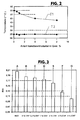
- die Temperatur des Heizers und des Kühlers der Messanordnung der
Figur 1 in Abhängigkeit von der Konzentration des Kohlenstoff-Nanofasermaterials in dem flüssigen Wärme transportierenden Mediums bzw. deren Basiskomponente; - Fig. 3
- in einer Graphik den gemessenen Wärmewiderstand Rth in Abhängigkeit von dem Anteil an Kohlenstoff-Nanofasermaterial, auch im Vergleich mit Wasser ohne Zusatz und mit Wasser mit einem PVA-Zusatz als Wärme transportierendes Medium;
- Fig. 4
- ein Bespiel für eine Anwendung des flüssigen wärmetransportierenden Mediums gemäß der Erfindung als Kühlmittel.
- Das wärmetransportierende Medium besteht aus einer Suspension aus Wasser als Basiskomponente und Nanofasermaterial, das bei dieser Ausführungsform der Erfindung zumindest zum überwiegenden Teil aus Nanotubes und/oder Nanofasern auf Kohlenstoffbasis besteht und zur Stabilisierung der Suspension vor dem Vermischen mit der Basiskomponente Wasser mit einem Polyvinylalkohol (PVA) vorbehandelt wurden. Diese Vorbehandlung z. B. erfolgt durch Mischen des Nanofasermaterials in einer PVA in höherer Konzentration enthaltenden Lösung, beispielsweise in einer Lösung mit einem PVA-Anteil von wenigstens 5 Gewichts% bezogen auf die Gesamtmasse der Lösung oder in einer gesättigten PVA-Lösung. Als Lösungsmittel dient hierbei z. B. Wasser.
- Das so mit PVA vorbehandelte bzw. dotierte Nanofasermaterial wird dann mit einer ausreichenden Menge an Wasser zu der das wärmetransportierende Medium bildenden wässrigen Suspension gemischt, wobei der Anteil an vorbehandeltem Nanofasermaterial in dem wärmetransportierenden Medium vorzugsweise kleiner als 15 - 20 Gewichts% bezogen auf das Gesamtgewicht des wärmetransportierenden Mediums ist, um für dieses ein optimales Strömungsverhalten zu gewährleisten, wie dies beispielsweise bei Verwendung als ein Kühler, Wärmetauscher oder dgl. durchströmendes Kühlmedium notwendig ist. Durch die Vorbehandlung mit PVA ist das Nanofasermaterial in Wasser gut dispergierbar, sodass das wärmetransportierende Medium eine stabile Suspension bildet.
- Durch die Vorbehandlung des Nanofasermaterials mit PVA bzw. durch das Aufbringen von PVA auf das Nanofasermaterial wird weiterhin auch ein Schmier- oder Gleiteffekt erreicht, und zwar u. a. mit dem Vorteil, dass das wärmetransportierende Medium Kanäle, Kammern oder dgl. schonend durchströmt und ein Abrieb an Innenflächen insbesondere auch von engen Kanälen, Kammern oder dgl. wirksam verhindert ist. Durch die PVA-Vorbehandlung wird weiterhin auch ein Verklumpen des Nanofasermaterials in dem wärmetransportierenden Medium verhindert.
- Als Nanofasermaterial eignen sich beispielsweise Nanofasern, die unter den Bezeichnungen "Pyrograf III" oder "HTF 150 FF-HHT" von der Electrovac AG, A-3400 Klosterneuburg, Österreich angeboten werden. Weitere, bei der Erfindung als Nanofasermaterial verwendbare Nanofasern, die ebenfalls von der Electrovac AG, A-3400 Klosterneuburg, Österreich angeboten werden, sind in der nachstehenden Tabelle aufgeführt.
Tabelle 1 Nano-faser Nano-fasertyp N2 Spezi-fische Ober-fläche [m2/g] Durch-messer [nm] Länge [µm] Wärmeleit-fähigkeit [W/mK] Elektri-scher Wider-stand [Ohm/cm] Metall-gehalt [wt. %] Dichte [g/cm3] HTF150FF AGF 10-20 100-200 >10 > 600 < 10-3 < 0,5 1,95 HTF150FF PSF 20-30 100-200 >10 > 600 < 10-3 < 0,5 1,95 HTF150FF LHT 15-20 100-200 >10 > 600 < 10-3 <0,5 > 1,95 HTF150FF HHT 15-25 100-200 >10 > 600 < 10-3 < 0,01 > 1,95 HTF110FF AGF 53 70-150 >10 >600 <10-3 < 0,5 1,95 HTF110FF PSF 50-60 70-150 >10 > 600 < 10-3 < 0,5 1,95 HTF110FF LHT 43 70-150 >10 > 600 < 10-3 < 0,5 > 1,95 HTF110F F HHT 41 70-150 >10 > 600 <10-3 <0,01 > 1,95 ENF100AA HTE 80-100 80-150 >10 > 600 < 10-3 < 0,5 1,98 ENF100AA GFE > 50 80-150 >10 > 600 <10-3 < 0,01 2,17 - Nanofasertyp:
- AGF wie gewachsen
- PSF pyrolytische stripped Carbon Nanofaser
- LHT ausgeheizt bei ∼ 1 000°C
- HHT ausgeheizt bei ∼ 3000°C
- HTE ausgeheizt bei ∼ 1000°C bei EVAC
- GFE ausgeheizt bei ∼ 3000°C bei EVAC
- In der
Figur 1 ist 1 eine Messanordnung, die zum Messen des thermischen Widerstandes Rth eines flüssigen wärmetransportierenden Mediums geeignet ist und im Wesentlichen aus einem elektrischen Heizer 2 an einer Oberflächenseite einer ersten, aus Kupfer bestehenden Platte 3, aus einer zweiten, ebenfalls aus Kupfer bestehenden Platte 4 und aus einem an einer Oberflächenseite dieser Platte vorgesehenen Kühler 5 besteht. Letzterer ist beispielsweise als passiver, d. h. durch die Umgebungsluft gekühlter Kühler oder aber als aktiver, d. h. als von einem Kühlmedium, nämlich von Wasser durchströmter Kühler ausgebildet. Die Platten 3 und 4 sind mit dem Heizelement 2 bzw. dem Kühler 5 jeweils flächig und thermisch in optimaler Weise, beispielsweise auch unter Verwendung einer in ihren Eigenschaften bekannten Wärmeleitpaste verbunden. Weiterhin sind die Platten 3 und 4 jeweils mit einem Temperatursensor 3.1 bzw. 4.1 zur Messung der Temperatur T1 der Platte 3 und der Temperatur T2 der Platte 4 versehen. Zwischen den einander zugewandten Seiten der Platten 3 und 4 ist ein Messspalt 6 gebildet, der bei der Messung vollständig von dem zu messenden wärmetransportierenden Medium ausgefüllt und durch eine entsprechende Dichtung 6.1 seitlich begrenzt ist, die ein unerwünschtes Herauslaufen des wärmetransportierenden Mediums aus dem Messspalt 6 verhindert und außerdem die Breite des Messspaltes 6 bzw. den Abstand der beiden Platten 3 und 4 definiert. Bei der dargestellten Ausführungsform beträgt die Breite des Messspaltes etwa 100 µm. - Der thermische Widerstand ist dabei, wie folgt, definiert:

- Mit der Messanordnung 1 wurde der thermische Widerstand verschiedener Proben gemessen, die das mit PVA vorbehandelte Nanofasermaterial in unterschiedlichen Konzentrationen enthielten, und zwar mit 0.5, 1.0, 2.0, 4.0 und 8.0 Gewichts%, jeweils bezogen auf das Gesamtgewicht bzw. die Gesamtmasse des wärmetransportierenden Mediums.
- In der
Figur 2 sind die gemessenen Temperaturen T1 und T2 angegeben. Während die Temperatur T2 der Messplatte 4 bzw. des Kühlers 5 im Wesentlichen konstant ist, nimmt die Temperatur der Platte 3 bzw. des Heizelementes 2 mit zunehmender Konzentration an Nanofasermaterial im wärmetransportierenden Medium ab, was bedeutet, dass der thermische Widerstand Rth mit zunehmendem Anteil an Nanofasermaterial abnimmt bzw. umgekehrt die thermische Leitfähigkeit des Materials mit zunehmendem Anteil an Nanofasermaterial zunimmt. - Die
Figur 3 zeigt den sich aus der Temperaturdifferenz T1 und T2 jeweils ergebenden thermischen Widerstand, und zwar für verschiedene Proben A - G, wobei diese Proben folgende Zusammensetzung aufweisen: - Probe A:
- Wasser ohne weitere Zusätze
- Probe B:
- Wasser mit PVA in einem Anteil von etwa 5 Gewichts%
- Probe C:
- Wasser und 0,5 Gewichts% an mit PVA vorbehandelten Nanofasermaterial
- Probe D:
- Wasser mit 1,0 Gewichts% an mit PVA vorbehandelten Nanofasermaterial
- Probe E:
- Wasser mit 2,0 Gewichts% an mit PVA vorbehandelten Nanofasermaterial
- Probe F:
- Wasser mit 4,0 Gewichts% an mit PVA vorbehandelten Nanofasermaterial
- Probe G:
- Wasser mit 8 Gewichts% an mit PVA vorbehandelten Nanofasermaterial jeweils bezogen auf das Gesamtgewicht der Probe.
- Bereits bei einem Anteil von 0,5 Gewichts% Nanofasermaterial ergibt sich gegenüber reinem Wasser eine Reduzierung des thermischen Widerstandes Rth um etwa 12%. Bei einem Anteil von 4 Gewichts% an Nanofasern wird eine Reduzierung des thermischen Widerstandes Rth gegenüber Wasser von etwa 38 % erreicht.
- Die Verwendung von PVA für die Vorbehandlung des Nanofasermaterials bzw. für die Stabilisierung des flüssigen wärmetransportierenden Mediums bietet auch den Vorteil, dass PVA toxikologisch unbedenklich und auch biologisch zumindest teilweise abbaubar und damit umweltverträglich ist.
- Die
Figur 4 zeigt in schematischer Darstellung ein in dieser Figur allgemein mit 7 bezeichnetes Kühlsystem zur Kühlung eines elektrischen Bauelementes, beispielsweise eines Prozessors 8 eines Rechners. Das wärmetransportierende Medium gemäß der Erfindung wird in diesem Kühlsystem 7 als Kühlmittel verwendet. Das Kühlsystem besteht in an sich bekannter Weise aus einem auf dem Prozessor 8 befestigten, von dem Kühlmittel durchströmbaren Bauelement-Kühler 9 und aus einem an der Außenseite des Gehäuses des Rechners vorgesehenen, ebenfalls von dem Kühlmedium durchströmten Außenkühler 10 mit entsprechendem Lüfter. Das Kühlsystem 7 umfasst weiterhin wenigstens einen Vorratsbehälter oder Reservoir 11 für das Kühlmittel sowie eine Umwälzpumpe 12, die zusammen mit dem Kühler 9 und dem Außenkühler 10 in einem geschlossenen Kühlmedium-Kreislauf angeordnet sind. - Durch die Reduzierung des thermischen Widerstandes des wärmetransportierenden Mediums und durch die damit einhergehende verbesserte Wärmeübertragung von dem Bauelement-Kühler 9 an das wärmetransportierende Medium bzw. Kühlmedium kann die Leistung des Kühlsystems 7, d. h. die je Zeiteinheit von dem Prozessor 8 abgeführte Wärmemenge wesentlich gesteigert werden.
-
- 1
- Messanordnung
- 2
- Heizelement
- 3, 4
- Messplatte
- 3.1, 4.1
- Temperatursensor
- 5
- Kühler
- 6
- Messspalt
- 6.1
- Dichtung
- 7
- Kühlkreis
- 8
- elektrisches Bauelement, beispielsweise Prozessor
- 9
- Bauelementkühler
- 10
- Außenkühler
- 11
- Reservoir für Kühlmedium
- 12
- Umwälzpumpe
Claims (8)
- Heiz- oder Kühlsystem mit wenigstens einem von einem Wärme transportierenden Medium durchströmten Wärmetauscher oder Kühler (9, 10),
wobei das Wärme transportierendes Medium aus einer zumindest teilweise von Wasser gebildeten flüssigen Matrix- oder Basis-Komponente mit einem Zusatz in Form wenigstens eines Polyvinylalkohol (PVA) besteht,
dadurch gekennzeichnet,
dass die flüssige Matrix- oder Basis-Komponente weiterhin ein Nanofasermaterial enthält. - Heiz- oder Kühlsystem nach Anspruch 1, dadurch gekennzeichnet, dass die flüssige Matrix- oder Basis-Komponente ein mit dem Polyvinylalkohol vorbehandeltes und/oder versehenes Nanofasermaterial enthält.
- Heiz- oder Kühlsystem nach Anspruch 1 oder 2, dadurch gekennzeichnet,das Nanofasermaterial ein solches auf Carbon- oder Kohlenstoffbasis ist.
- Heiz- oder Kühlsystem nach einem der vorhergehenden Ansprüche, dadurch gekennzeichnet, dass das Nanofasermaterial Nanofasern und/oder Nanotubes enthält.
- Heiz- oder Kühlsystem nach einem der vorhergehenden Ansprüche, dadurch gekennzeichnet, dass das Nanofasermaterial durch Vermischen mit einer Polyvinylalkohol enthaltenden Vorbehandlungslösung vorbehandelt ist,
wobei die Vorbehandlungslösung beispielsweise 5Gewichts% Polyvinylalkohol enthält oder eine gesättigte Polyvinylalkohol-Lösung ist.. - Heiz- oder Kühlsystem nach einem der vorhergehenden Ansprüche, dadurch gekennzeichnet, dass die flüssige Basiskomponente bezogen auf das Gesamtgewicht des Wärme transportierenden Mediums maximal 15 Gewichts% Nanofasermaterial enthält, vorzugsweise mit Polyvinylalkohol vorbehandeltes Nanofasermaterial.
- Heiz- oder Kühlsystem nach einem der vorhergehenden Ansprüche, dadurch gekennzeichnet, dass die Basiskomponente bezogen auf das Gesamtgewicht 0,5 Gewichts% oder 1,0 Gewichts% oder 2,0 Gewichts% oder 4,0 Gewichts% oder 8,0 Gewichts% Nanofasermaterial enthält.
- Heiz- oder Kühlsystem nach einem der vorhergehenden Ansprüche, gekennzeichnet durch seine Ausbildung als Kühlsystem für elektrische Bauelemente (8).
Applications Claiming Priority (2)
| Application Number | Priority Date | Filing Date | Title |
|---|---|---|---|
| DE102006001335.2A DE102006001335B4 (de) | 2006-01-09 | 2006-01-09 | Verwendung eines wärmetransportierenden Mediums |
| PCT/IB2006/003769 WO2007080447A2 (de) | 2006-01-09 | 2006-11-30 | Wärmetransportierendes medium sowie heiz- oder kühlsystem mit einem solchen medium |
Publications (2)
| Publication Number | Publication Date |
|---|---|
| EP2029692A2 EP2029692A2 (de) | 2009-03-04 |
| EP2029692B1 true EP2029692B1 (de) | 2012-01-11 |
Family
ID=38169952
Family Applications (1)
| Application Number | Title | Priority Date | Filing Date |
|---|---|---|---|
| EP06842275A Not-in-force EP2029692B1 (de) | 2006-01-09 | 2006-11-30 | Wärmetransportierendes medium sowie heiz- oder kühlsystem mit einem solchen medium |
Country Status (5)
| Country | Link |
|---|---|
| US (1) | US20090008062A1 (de) |
| EP (1) | EP2029692B1 (de) |
| JP (1) | JP2009522424A (de) |
| DE (1) | DE102006001335B4 (de) |
| WO (1) | WO2007080447A2 (de) |
Families Citing this family (3)
| Publication number | Priority date | Publication date | Assignee | Title |
|---|---|---|---|---|
| DE102010028800A1 (de) | 2010-05-10 | 2011-11-10 | Freie Universität Berlin | Polymer-Zusammensetzungen auf Basis umweltfreundlicher pflanzlicher und/oder tierischer Öle als wärmeleitfähige Materialien |
| US10468124B2 (en) | 2012-01-23 | 2019-11-05 | Toyota Motor Engineering & Manufacturing North America, Inc. | Process for designing and producing cooling fluids |
| JP7546558B2 (ja) * | 2019-05-21 | 2024-09-06 | 株式会社巴川コーポレーション | 温調ユニット |
Family Cites Families (18)
| Publication number | Priority date | Publication date | Assignee | Title |
|---|---|---|---|---|
| NL297360A (de) * | 1962-09-04 | |||
| FR2191091B1 (de) * | 1972-07-04 | 1975-03-07 | Rhone Poulenc Ind | |
| JPS62156910A (ja) * | 1985-12-28 | 1987-07-11 | ダイセル化学工業株式会社 | 押出成型用粘結剤 |
| US5576162A (en) * | 1996-01-18 | 1996-11-19 | Eastman Kodak Company | Imaging element having an electrically-conductive layer |
| WO2000016618A1 (en) * | 1998-09-21 | 2000-03-30 | 21St Century Medicine, Inc. | Improved cryoprotectant solutions |
| US6555945B1 (en) * | 1999-02-25 | 2003-04-29 | Alliedsignal Inc. | Actuators using double-layer charging of high surface area materials |
| JP3111219B1 (ja) * | 1999-05-25 | 2000-11-20 | 工業技術院長 | ポリビニルアルコールを利用した冷熱輸送方法及び装置 |
| CA2404466A1 (en) * | 2000-03-29 | 2001-10-04 | Altana Pharma Ag | Pyrano[2,3-c]imidazo[-1,2-a]pyridine derivatives for the treatment of gastrointestinal disorders |
| US6881364B2 (en) * | 2001-05-16 | 2005-04-19 | U.S. Environmental Protection Agency | Hydrophilic mixed matrix materials having reversible water absorbing properties |
| US7348298B2 (en) * | 2002-05-30 | 2008-03-25 | Ashland Licensing And Intellectual Property, Llc | Enhancing thermal conductivity of fluids with graphite nanoparticles and carbon nanotube |
| JP4264804B2 (ja) * | 2002-12-03 | 2009-05-20 | 東洋紡績株式会社 | 導電性樹脂組成物 |
| US20040219093A1 (en) * | 2003-04-30 | 2004-11-04 | Gene Kim | Surface functionalized carbon nanostructured articles and process thereof |
| US20050037082A1 (en) * | 2003-08-13 | 2005-02-17 | Wan-Kei Wan | Poly(vinyl alcohol)-bacterial cellulose nanocomposite |
| TWM246562U (en) * | 2003-10-31 | 2004-10-11 | Hon Hai Prec Ind Co Ltd | Heat pipe |
| CN1922363B (zh) * | 2004-02-19 | 2011-04-13 | 东丽株式会社 | 纳米纤维配合溶液、乳液和凝胶状物及其制造方法,以及纳米纤维合成纸及其制造方法 |
| JP2005342937A (ja) * | 2004-06-01 | 2005-12-15 | National Printing Bureau | 印刷機用ローラ及びその製造方法 |
| US7485233B2 (en) * | 2005-02-09 | 2009-02-03 | U.S. Environmental Protection Agency | Hydrophilic mixed matrix material having reversible water absorbing properties |
| TWI333826B (en) * | 2005-11-30 | 2010-11-21 | Heat transfer fluids with carbon nanocapsules |
-
2006
- 2006-01-09 DE DE102006001335.2A patent/DE102006001335B4/de not_active Expired - Fee Related
- 2006-11-30 WO PCT/IB2006/003769 patent/WO2007080447A2/de not_active Ceased
- 2006-11-30 JP JP2008549068A patent/JP2009522424A/ja active Pending
- 2006-11-30 EP EP06842275A patent/EP2029692B1/de not_active Not-in-force
- 2006-11-30 US US12/087,335 patent/US20090008062A1/en not_active Abandoned
Also Published As
| Publication number | Publication date |
|---|---|
| DE102006001335A1 (de) | 2007-07-12 |
| EP2029692A2 (de) | 2009-03-04 |
| JP2009522424A (ja) | 2009-06-11 |
| WO2007080447A3 (de) | 2007-11-08 |
| US20090008062A1 (en) | 2009-01-08 |
| WO2007080447A2 (de) | 2007-07-19 |
| DE102006001335B4 (de) | 2016-08-04 |
Similar Documents
| Publication | Publication Date | Title |
|---|---|---|
| DE102018216708A1 (de) | Kühlplatte zur Temperierung zumindest einer Batteriezelle und Batteriesystem | |
| DE102015114091A1 (de) | Gassensorelement und Gassensor | |
| EP2880962B1 (de) | Aufheizeinrichtung für einen betriebs-/hilfsstoff mit ausgleichselement | |
| EP3749731B1 (de) | Thermisches kontakt- und füllmaterial und akkumulator-anordnung mit einem thermischen kontakt- und füllmaterial | |
| DE102019115663A1 (de) | Baugruppen mit verbesserter wärmeübertragung durch vaskuläre kanäle und verfahren zur herstellung von vaskulären kanälen | |
| DE112012005520T5 (de) | Kolben far Verbrennungsmotor | |
| DE102008013134A1 (de) | Wärmetauschvorrichtung und Verfahren zum Herstellen eines Wärmetauschelements für eine Wärmetauschvorrichtung | |
| DE102005021529A1 (de) | Entfernung von Wasserstoff von einem Kühlmittelfluid | |
| DE102006001335B4 (de) | Verwendung eines wärmetransportierenden Mediums | |
| DE102009028848A1 (de) | Aufbau und Herstellungsverfahrens eines Sensors eines thermischen Durchflussmessgeräts | |
| EP1285213B1 (de) | Mikrostruktur-wärmetauscher und verfahren zu dessen herstellung | |
| DE102018203435B4 (de) | Verfahren zur Herstellung einer umfangsbeschichteten Wabenstruktur und umfangsbeschichtete Wabenstruktur | |
| DE102013210967A1 (de) | Röntgenstrahler | |
| EP4016609A1 (de) | Vorrichtung mit bauelement und angekoppeltem kühlkörper | |
| DE102011077959A1 (de) | Ventilanordnung | |
| DE202024101181U1 (de) | Zündkerze | |
| DE3419060C1 (de) | Motorlager,insbesondere Hydrolager | |
| WO2008107734A1 (de) | Beschichtungsmaterial bzw. lack mit verbesserter wärmeübertragung sowie wärme übertragende oberfläche mit einer unter verwendung des reschichtungsmaterials hergestellten beschichtung | |
| DE102007039903A1 (de) | Wärmeleitmaterial mit zwei Materialbestandteilen und Verwendung des Wärmeleitmaterials | |
| DE10336657B4 (de) | Verbundwerkstoff, insbesondere für Wärmetauscher, Wärmeleiter und Wärmespeicher | |
| EP3367426A1 (de) | Halbleitermodul mit kühlkörper | |
| DE102015220395A1 (de) | Rußpartikelsensor | |
| DE102013015787A1 (de) | Temperiervorrichtung für eine Batterie | |
| DE202011001278U1 (de) | Temperaturfühler zur Messung hoher Temperaturen gasförmiger und/oder flüssiger Medien | |
| EP3844030A1 (de) | Kühlvorrichtung für bauteile in einem fahrzeug |
Legal Events
| Date | Code | Title | Description |
|---|---|---|---|
| PUAI | Public reference made under article 153(3) epc to a published international application that has entered the european phase |
Free format text: ORIGINAL CODE: 0009012 |
|
| 17P | Request for examination filed |
Effective date: 20080607 |
|
| AK | Designated contracting states |
Kind code of ref document: A2 Designated state(s): AT BE BG CH CY CZ DE DK EE ES FI FR GB GR HU IE IS IT LI LT LU LV MC NL PL PT RO SE SI SK TR |
|
| AX | Request for extension of the european patent |
Extension state: AL BA HR MK RS |
|
| 17Q | First examination report despatched |
Effective date: 20090428 |
|
| RBV | Designated contracting states (corrected) |
Designated state(s): DE FR GB |
|
| RAP1 | Party data changed (applicant data changed or rights of an application transferred) |
Owner name: CURAMIK ELECTRONICS GMBH |
|
| GRAP | Despatch of communication of intention to grant a patent |
Free format text: ORIGINAL CODE: EPIDOSNIGR1 |
|
| DAX | Request for extension of the european patent (deleted) | ||
| GRAS | Grant fee paid |
Free format text: ORIGINAL CODE: EPIDOSNIGR3 |
|
| GRAA | (expected) grant |
Free format text: ORIGINAL CODE: 0009210 |
|
| AK | Designated contracting states |
Kind code of ref document: B1 Designated state(s): DE FR GB |
|
| REG | Reference to a national code |
Ref country code: GB Ref legal event code: FG4D Free format text: NOT ENGLISH |
|
| REG | Reference to a national code |
Ref country code: DE Ref legal event code: R096 Ref document number: 502006010860 Country of ref document: DE Effective date: 20120308 |
|
| PLBE | No opposition filed within time limit |
Free format text: ORIGINAL CODE: 0009261 |
|
| STAA | Information on the status of an ep patent application or granted ep patent |
Free format text: STATUS: NO OPPOSITION FILED WITHIN TIME LIMIT |
|
| 26N | No opposition filed |
Effective date: 20121012 |
|
| REG | Reference to a national code |
Ref country code: DE Ref legal event code: R097 Ref document number: 502006010860 Country of ref document: DE Effective date: 20121012 |
|
| REG | Reference to a national code |
Ref country code: DE Ref legal event code: R082 Ref document number: 502006010860 Country of ref document: DE Representative=s name: GRAF GLUECK KRITZENBERGER, DE |
|
| REG | Reference to a national code |
Ref country code: DE Ref legal event code: R081 Ref document number: 502006010860 Country of ref document: DE Owner name: ROGERS GERMANY GMBH, DE Free format text: FORMER OWNER: CURAMIK ELECTRONICS GMBH, 92676 ESCHENBACH, DE Effective date: 20140729 Ref country code: DE Ref legal event code: R082 Ref document number: 502006010860 Country of ref document: DE Representative=s name: GRAF GLUECK KRITZENBERGER, DE Effective date: 20140729 Ref country code: DE Ref legal event code: R082 Ref document number: 502006010860 Country of ref document: DE Representative=s name: GLUECK - KRITZENBERGER PATENTANWAELTE PARTGMBB, DE Effective date: 20140729 |
|
| REG | Reference to a national code |
Ref country code: FR Ref legal event code: PLFP Year of fee payment: 10 |
|
| PGFP | Annual fee paid to national office [announced via postgrant information from national office to epo] |
Ref country code: GB Payment date: 20151130 Year of fee payment: 10 |
|
| PGFP | Annual fee paid to national office [announced via postgrant information from national office to epo] |
Ref country code: FR Payment date: 20151130 Year of fee payment: 10 |
|
| PGFP | Annual fee paid to national office [announced via postgrant information from national office to epo] |
Ref country code: DE Payment date: 20160129 Year of fee payment: 10 |
|
| REG | Reference to a national code |
Ref country code: DE Ref legal event code: R119 Ref document number: 502006010860 Country of ref document: DE |
|
| GBPC | Gb: european patent ceased through non-payment of renewal fee |
Effective date: 20161130 |
|
| REG | Reference to a national code |
Ref country code: FR Ref legal event code: ST Effective date: 20170731 |
|
| PG25 | Lapsed in a contracting state [announced via postgrant information from national office to epo] |
Ref country code: FR Free format text: LAPSE BECAUSE OF NON-PAYMENT OF DUE FEES Effective date: 20161130 |
|
| PG25 | Lapsed in a contracting state [announced via postgrant information from national office to epo] |
Ref country code: GB Free format text: LAPSE BECAUSE OF NON-PAYMENT OF DUE FEES Effective date: 20161130 Ref country code: DE Free format text: LAPSE BECAUSE OF NON-PAYMENT OF DUE FEES Effective date: 20170601 |