EP2029318B1 - Verfahren zur herstellung eines einteiligen kolbens - Google Patents
Verfahren zur herstellung eines einteiligen kolbens Download PDFInfo
- Publication number
- EP2029318B1 EP2029318B1 EP07722518A EP07722518A EP2029318B1 EP 2029318 B1 EP2029318 B1 EP 2029318B1 EP 07722518 A EP07722518 A EP 07722518A EP 07722518 A EP07722518 A EP 07722518A EP 2029318 B1 EP2029318 B1 EP 2029318B1
- Authority
- EP
- European Patent Office
- Prior art keywords
- piston
- cooling channel
- recess
- tool
- cooling duct
- Prior art date
- Legal status (The legal status is an assumption and is not a legal conclusion. Google has not performed a legal analysis and makes no representation as to the accuracy of the status listed.)
- Ceased
Links
Images

Classifications
-
- B—PERFORMING OPERATIONS; TRANSPORTING
- B23—MACHINE TOOLS; METAL-WORKING NOT OTHERWISE PROVIDED FOR
- B23P—METAL-WORKING NOT OTHERWISE PROVIDED FOR; COMBINED OPERATIONS; UNIVERSAL MACHINE TOOLS
- B23P15/00—Making specific metal objects by operations not covered by a single other subclass or a group in this subclass
- B23P15/10—Making specific metal objects by operations not covered by a single other subclass or a group in this subclass pistons
-
- B—PERFORMING OPERATIONS; TRANSPORTING
- B23—MACHINE TOOLS; METAL-WORKING NOT OTHERWISE PROVIDED FOR
- B23B—TURNING; BORING
- B23B1/00—Methods for turning or working essentially requiring the use of turning-machines; Use of auxiliary equipment in connection with such methods
-
- B—PERFORMING OPERATIONS; TRANSPORTING
- B23—MACHINE TOOLS; METAL-WORKING NOT OTHERWISE PROVIDED FOR
- B23B—TURNING; BORING
- B23B27/00—Tools for turning or boring machines; Tools of a similar kind in general; Accessories therefor
- B23B27/04—Cutting-off tools
-
- B—PERFORMING OPERATIONS; TRANSPORTING
- B23—MACHINE TOOLS; METAL-WORKING NOT OTHERWISE PROVIDED FOR
- B23B—TURNING; BORING
- B23B27/00—Tools for turning or boring machines; Tools of a similar kind in general; Accessories therefor
- B23B27/06—Profile cutting tools, i.e. forming-tools
-
- B—PERFORMING OPERATIONS; TRANSPORTING
- B23—MACHINE TOOLS; METAL-WORKING NOT OTHERWISE PROVIDED FOR
- B23B—TURNING; BORING
- B23B5/00—Turning-machines or devices specially adapted for particular work; Accessories specially adapted therefor
-
- F—MECHANICAL ENGINEERING; LIGHTING; HEATING; WEAPONS; BLASTING
- F02—COMBUSTION ENGINES; HOT-GAS OR COMBUSTION-PRODUCT ENGINE PLANTS
- F02F—CYLINDERS, PISTONS OR CASINGS, FOR COMBUSTION ENGINES; ARRANGEMENTS OF SEALINGS IN COMBUSTION ENGINES
- F02F3/00—Pistons
- F02F3/16—Pistons having cooling means
- F02F3/20—Pistons having cooling means the means being a fluid flowing through or along piston
- F02F3/22—Pistons having cooling means the means being a fluid flowing through or along piston the fluid being liquid
-
- B—PERFORMING OPERATIONS; TRANSPORTING
- B23—MACHINE TOOLS; METAL-WORKING NOT OTHERWISE PROVIDED FOR
- B23B—TURNING; BORING
- B23B2215/00—Details of workpieces
- B23B2215/24—Components of internal combustion engines
-
- B—PERFORMING OPERATIONS; TRANSPORTING
- B23—MACHINE TOOLS; METAL-WORKING NOT OTHERWISE PROVIDED FOR
- B23B—TURNING; BORING
- B23B2215/00—Details of workpieces
- B23B2215/24—Components of internal combustion engines
- B23B2215/245—Pistons
-
- B—PERFORMING OPERATIONS; TRANSPORTING
- B23—MACHINE TOOLS; METAL-WORKING NOT OTHERWISE PROVIDED FOR
- B23B—TURNING; BORING
- B23B2270/00—Details of turning, boring or drilling machines, processes or tools not otherwise provided for
- B23B2270/54—Methods of turning, boring or drilling not otherwise provided for
-
- Y—GENERAL TAGGING OF NEW TECHNOLOGICAL DEVELOPMENTS; GENERAL TAGGING OF CROSS-SECTIONAL TECHNOLOGIES SPANNING OVER SEVERAL SECTIONS OF THE IPC; TECHNICAL SUBJECTS COVERED BY FORMER USPC CROSS-REFERENCE ART COLLECTIONS [XRACs] AND DIGESTS
- Y10—TECHNICAL SUBJECTS COVERED BY FORMER USPC
- Y10T—TECHNICAL SUBJECTS COVERED BY FORMER US CLASSIFICATION
- Y10T29/00—Metal working
- Y10T29/49—Method of mechanical manufacture
- Y10T29/49229—Prime mover or fluid pump making
- Y10T29/49249—Piston making
Definitions
- the present invention relates to a method for producing a one-piece piston for an internal combustion engine according to the preamble of patent claim 1. Such a method is known from the German patent DE 100 13 395 C1 known.
- Such a piston made of steel by casting is known in practice.
- releasable casting cores must be used, which complicate and increase the cost of the manufacturing process.
- a one-piece, from a forged piston blank machined piston is known from the German patent DE 100 13 395 C1 known.
- an annular recess is incorporated, which is then supplemented by a further axial recess. Only then is this axial recess processed in the second step to the finished cooling channel to the end.
- the piston must be stopped in its rotational movement in a predetermined position, namely in that position in which the rotary tool between the Kolben2020ften can be introduced. Only after the insertion of the rotary tool, the piston is set back in rotation and worked out the cooling channel.
- the turning tools move only in the radial and axial direction to the piston axis. This has the consequence that the height of the cooling channel thus produced is dependent on the height of the recess between the piston head and the box-shaped piston skirt.
- the height of the cooling channel is always lower than twice the height of the recess between the piston head and the piston skirt, because not only the height of this recess, but also the thickness of the tools used limits the achievable height of the cooling channel.
- the present invention has for its object to provide a method for producing a one-piece piston, wherein the height of the cooling channel can be designed independently of the height of the recess between the piston head and the piston shaft and soft can be performed without the rotational movement of the piston interrupt.
- the solution consists in a method with the features of claim 1. It is inventively provided that for machining the cooling channel, a tool with rotating piston moves in an arcuate pivoting movement through the recess in the region of the cooling channel and the cooling channel is worked out.
- the inventive method makes it possible for the first time to make the height of the cooling channel regardless of the height of the recess between the piston head and piston skirt.
- the inventive arcuate pivotal movement of the tool which is not performed parallel to the piston hub surfaces, causes the dimensions of the tool used are not limited by the height of the recess between the piston head and piston skirt.
- the height of the cooling channel can thus be adapted at any time to the requirements of the respective piston to be produced.
- the inventive method can be used in a variety of piston types.
- the present invention is further characterized in that the cooling channel can be made in a single step with a single tool from the annular recess between the piston head and piston skirt. This saves labor and tooling costs, which can reduce overall manufacturing costs.
- the arcuate pivotal movement of the tool through the recess in the region of the cooling channel takes place with rotating piston blank.
- the piston blank can thus be kept in a constant rotational movement, which further simplifies the course of the method according to the invention and saves time and energy.
- a further advantageous embodiment is that the machining of the cooling channel already takes place during the arcuate pivoting movement of the tool. This allows a continuous production process with the corresponding time and cost savings, but makes the inventive method also independent of the height of the recess between the piston head and piston skirt.
- a tool suitable for the method according to the invention is, for example, a turning tool, in particular a hook-shaped turning tool.
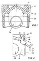
- FIG. 1 is a one-piece forged piston blank 10 is shown, which is made in the embodiment of a known drop forging method. With dash-dotted lines, the contour of the finished piston 20 is indicated.
- the piston blank 10 comprises a piston head 11 with the later piston ring band 12, a piston skirt 13 and piston bosses 14 attached to the piston head 11, and may be made of, for example, a malleable steel or a light metal alloy such as an aluminum alloy.
- FIGS. 2 to 6 the process steps for producing a cooling channel 15 according to the invention in the region of the piston ring band 12 are shown.
- an annular recess 16 by machining, in the embodiment by rotation, attached In a first method step, in the piston blank 10, an annular recess 16 by machining, in the embodiment by rotation, attached.
- the height of the recess 16 only needs to be so great that a tool, in the exemplary embodiment a hook-shaped turning tool 17, can be moved in an arc-shaped pivoting movement into the region of the cooling channel 15 to be produced with the piston rotating.
- a tool in the exemplary embodiment a hook-shaped turning tool 17
- the hook-shaped turning tool 17 is now moved with a rotating piston in an arcuate pivoting movement A into the region of the cooling channel 15 to be produced. Because of this arcuate pivoting movement, the height of the recess 16 may be substantially smaller than the height h of the hook-shaped turning tool 17. This has the consequence that the height h of the turning tool 17 can be selected higher than the height of the recess 16 so that in the axial direction a cooling channel 15 can be worked out, the depth of which can not only be much larger than the height of the recess 16, but whose depth can be selected completely independent of the height of the recess 16.
- cooling channel 15 is produced in a single operation with a single tool 17 such as.
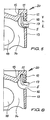
- FIGS. 2 to 6 is the arcuate pivotal movement of the tool, illustrated in the embodiment of the hook-shaped turning tool 17, in individual steps.
- the representation of the piston blank 10 was replaced by the representation of the finished piston 20.
- FIG. 2 shows the attachment of the turning tool 17 to the piston blank in a tilted angular position.
- FIG. 3 shows the penetration of the turning tool 17 through the recess 16 in the region of the cooling channel 15, wherein the turning tool 17 performs not only a radial and an axial movement, but also a pivoting movement about the pivot point S.
- FIG. 4 shows the turning tool 17 during the arcuate pivoting movement about the pivot point S, in which the shape of the cooling channel 15 is worked out.
- FIG. 5 shows the turning tool 17 at the end of its pivotal movement about the pivot point S in the transition to a further axial movement.
- the turning tool 17 has a substantially greater height h than the recess 16.
- FIG. 6 finally shows how the turning tool 17 reaches its end position and the cooling channel 15 has received its final shape and depth.
- hub bores 18 are introduced in a known manner, and the outer contour of the piston 20 is machined finished.
- a two-part cover ring for example a split plate spring
- the cover ring is provided with a supply and a discharge opening for the cooling oil (not shown).
- a one-piece piston is produced in a particularly simple and cost-effective manner with a large-volume cooling channel which, due to its free choice of material - forged steel or malleable light alloy - compared with pistons produced by casting, for example. has higher strengths, so that it is very well suited especially for high-pressure diesel engines.
Landscapes
- Engineering & Computer Science (AREA)
- Mechanical Engineering (AREA)
- Physics & Mathematics (AREA)
- Fluid Mechanics (AREA)
- Chemical & Material Sciences (AREA)
- Combustion & Propulsion (AREA)
- General Engineering & Computer Science (AREA)
- Pistons, Piston Rings, And Cylinders (AREA)
Abstract
Description
- Die vorliegende Erfindung betrifft ein Verfahren zur Herstellung eines einteiligen Kolbens für einen Verbrennungsmotor nach dem Oberbegriff des Patentanspruchs 1. Ein solches Verfahren ist aus der deutschen Patentschrift
DE 100 13 395 C1 bekannt. - Ein derartiger aus Stahl im Gießverfahren hergestellter Kolben ist aus der Praxis bekannt. Um hierbei einen geschlossenen Kühlkanal zu erhalten, müssen auslösbare Gießkeme verwendet werden, die das Herstefiungsverfahren verkomplizieren und verteuern.
- Ein einteiliger, aus einem geschmiedeten Kolbenrohling gearbeiteter Kolben ist aus der deutschen Patentschrift
DE 100 13 395 C1 bekannt. Zur Herstellung des Kühlkanals sind dazu zwei unterschiedliche Arbeitsschritte erforderlich, die mit unterschiedlichen Drehwerkzeugen bei drehendem Kolben ausgeführt werden müssen. Im ersten Arbeitsschritt wird eine ringförmige Ausnehmung eingearbeitet, die dann um eine weitere axiale Ausnehmung ergänzt wird. Erst anschließend wird diese axiale Ausnehmung im zweiten Arbeitsschritt zum fertigen Kühlkanal zu Ende bearbeitet. Dabei ist es von Nachteil, dass zum Einführung der Drehwerkzeuge der Kolben in seiner Drehbewegung in einer vorbestimmten Stellung angehalten werden muss, nämlich in derjenigen Stellung, in der das Drehwerkzeug zwischen den Kolbenschäften eingeführt werden kann. Erst nach dem Einführen des Drehwerkzeugs wird der Kolben wieder in Drehung versetzt und der Kühlkanal ausgearbeitet. - Die Drehwerkzeuge bewegen sich dabei ausschließlich in radialer und axialer Richtung zur Kolbenachse. Das hat zur Folge, dass die Höhe des so hergestellten Kühlkanals von der Höhe der Ausnehmung zwischen dem Kolbenkopf und dem kastenförmigen Kolbenschaft abhängig ist. Die Höhe des Kühlkanals ist immer geringer als die doppelte Höhe der Ausnehmung zwischen Kolbenkopf und Kolbenschaft, weil nicht nur die Höhe dieser Ausnehmung, sondern auch die Dicke der verwendeten Werkzeuge die erreichbare Höhe des Kühlkanals begrenzt.
- Der vorliegenden Erfindung liegt die Aufgabe zugrunde, ein Verfahren zur Herstellung eines einteiligen Kolbens bereitzustellen, bei dem die Höhe des Kühlkanals unabhängig von der Höhe der Ausnehmung zwischen dem Kolbenkopf und dem Kolbenschaft gestaltet werden kann und weiches ausgeführt werden kann, ohne die Drehbewegung des Kolbens zu unterbrechen.
- Die Lösung besteht in einem Verfahren mit den Merkmalen des Patentanspruchs 1. Dabei ist erfindungsgemäß vorgesehen, dass zur spanabhebenden Bearbeitung des Kühlkanals ein Werkzeug bei drehendem Kolben in einer bogenförmigen Schwenkbewegung durch die Ausnehmung in den Bereich des Kühlkanals hineinbewegt und der Kühlkanal ausgearbeitet wird.
- Das erfindungsgemäße Verfahren erlaubt es erstmals, die Höhe des Kühlkanals unabhängig von der Höhe der Ausnehmung zwischen Kolbenkopf und Kolbenschaft zu gestalten. Die erfindungsgemäße bogenförmige Schwenkbewegung des Werkzeugs, die nicht parallel zu den Kolbennabenflächen ausgeführt wird, bewirkt, dass die Abmessungen des verwendeten Werkzeugs nicht von der Höhe der Ausnehmung zwischen Kolbenkopf und Kolbenschaft begrenzt werden. Die Höhe des Kühlkanals kann somit jederzeit den Anforderungen an den jeweils herzustellenden Kolben angepasst werden. Damit kann das erfindungsgemäße Verfahren bei den unterschiedlichsten Kolbentypen zur Anwendung kommen.
- Die vorliegende Erfindung zeichnet sich ferner dadurch aus, dass der Kühlkanal in einem einzigen Arbeitsschritt mit einem einzigen Werkzeug ausgehend von der ringförmigen Ausnehmung zwischen Kolbenkopf und Kolbenschaft hergestellt werden kann. Dies erspart Arbeitszeit und Werkzeugkosten, wodurch die Herstellungskosten insgesamt gesenkt werden können.
- Vorteilhafte Weiterbildungen ergeben sich aus den Unteransprüchen.
- Bei einer bevorzugten Ausführungsform erfolgt die bogenförmige Schwenkbewegung des Werkzeugs durch die Ausnehmung in den Bereich des Kühlkanals bei sich drehendem Kolbenrohling. Der Kolbenrohling kann also in einer ständigen Drehbewegung gehalten werden, was den Ablauf des erfindungsgemäßen Verfahrens weiter vereinfacht und Zeit sowie Energie einspart.
- Eine weitere vorteilhafte Ausgestaltung besteht darin, dass die spanabhebende Bearbeitung des Kühlkanals bereits während der bogenförmigen Schwenkbewegung des Werkzeugs erfolgt. Dies ermöglicht einen kontinuierlichen Herstellungsprozess mit der entsprechenden Zeit- und Kostenersparnis, sondern macht das erfindungsgemäße Verfahren auch unabhängig von der Höhe der Ausnehmung zwischen Kolbenkopf und Kolbenschaft.
- Ein für das erfindungsgemäße Verfahren geeignetes Werkzeug ist bspw. ein Drehmeißel, insbesondere ein hakenförmiger Drehmeißel.
- Ein Ausführungsbeispiel der vorliegenden Erfindung wird im Folgenden anhand der beigefügten Zeichnungen näher erläutert. Es zeigen in einer schematischen, nicht maßstabsgetreuen Darstellung:
- Figur 1
- einen Kolbenrohling mit strichpunktiert angedeutetem erfindungsgemä- ßem Kolben in Seitenansicht im Schnitt;
- Figuren 2 bis 6
- eine Darstellung der bogenförmigen Schwenkbewegung eines Drehmeißels durch die Ausnehmung in den Bereich des Kühlkanals ge- mäß der Erfindung.
- In
Figur 1 ist ein einteiliger geschmiedeter Kolbenrohling 10 dargestellt, der im Ausführungsbeispiel nach einem an sich bekannten Gesenkschmiedeverfahren hergestellt ist. Mit strichpunktierten Linien ist die Kontur des fertigen Kolbens 20 angedeutet. Der Kolbenrohling 10 umfasst einen Kolbenkopf 11 mit dem späteren Kolbenringband 12, einen Kolbenschaft 13 und an den Kolbenkopf 11 angehängte Kolbennaben 14 und kann bspw. aus einem schmiedbaren Stahl oder einer Leichtmetall-Legierung wie zum Beispiel einer Aluminium-Legierung hergestellt werden. - In den
Figuren 2 bis 6 sind die Verfahrensschritte zur erfindungsgemäßen Herstellung eines Kühlkanals 15 im Bereich des Kolbenringbandes 12 dargestellt. - In einem ersten Verfahrensschritt wird bei dem Kolbenrohling 10 eine ringförmige Ausnehmung 16 durch spanabhebende Bearbeitung, im Ausführungsbeispiel durch Drehen, angebracht. Die Höhe der Ausnehmung 16 muss nur so groß sein, dass ein Werkzeug, im Ausführungsbeispiel ein hakenförmiger Drehmeißel 17, bei sich drehendem Kolben in einer bogenförmigen Schwenkbewegung in den Bereich des herzustellenden Kühlkanals 15 hineinbewegbar ist. Durch diese Ausnehmung 16 ist der Kolbenkopf 11 nur noch über die Kolbennaben 14 mit dem Kolbenschaft 13 verbunden.
- Zur Herstellung des ringförmig umlaufenden Kühlkanals 15 im Bereich des Kolbenringbandes 12 wird nun der hakenförmige Drehmeißel 17 bei sich drehendem Kolben in einer bogenförmigen Schwenkbewegung A in den Bereich des herzustellenden Kühlkanals 15 hineinbewegt. Aufgrund dieser bogenförmigen Schwenkbewegung kann die Höhe der Ausnehmung 16 wesentlich kleiner sein als die Höhe h des hakenförmigen Drehmeißels 17. Das hat zur Folge, dass die Höhe h des Drehmeißels 17 höher gewählt werden kann als die Höhe der Ausnehmung 16, so dass in axialer Richtung ein Kühlkanal 15 herausgearbeitet werden kann, dessen Tiefe nicht nur wesentlich größer sein kann als die Höhe der Ausnehmung 16, sondern dessen Tiefe völlig unabhängig von der Höhe der Ausnehmung 16 gewählt werden kann. Bei optimierter Ausbildung und Wegführung des Drehmeißels 17 kann eine völlig beliebige und nahezu unbegrenzte Tiefe des Kühlkanals 15 erreicht werden. Damit können mit dem erfindungsgemäßen Verfahren verschiedenste Typen von einteiligen Kolben hergestellt werden, die optimal an die Anforderungen des jeweiligen Motortyps angepasst werden können.
- Hervorzuheben ist ferner, dass der Kühlkanal 15 in einem einzigen Arbeitsschritt mit einem einzigen Werkzeug 17 wie bspw. dem oben erwähnten hakenförmigen Drehmeißel, bei sich drehendem Kolben hergestellt wird.
- In den
Figuren 2 bis 6 ist die bogenförmige Schwenkbewegung des Werkzeugs, im Ausführungsbeispiel des hakenförmigen Drehmeißels 17, in einzelnen Schritten veranschaulicht. Dabei wurde aus Gründen der Anschaulichkeit die Darstellung des Kolbenrohlings 10 durch die Darstellung des fertigen Kolbens 20 ersetzt. - Die
Figur 2 zeigt das Ansetzen des Drehmeißels 17 an den Kolbenrohling in einer gekippten Winkellage. - Die
Figur 3 zeigt das Eindringen des Drehmeißels 17 durch die Ausnehmung 16 in den Bereich des Kühlkanals 15, wobei der Drehmeißel 17 nicht nur eine radiale und eine axiale Bewegung, sondern auch eine Schwenkbewegung um den Schwenkpunkt S ausführt. - Die
Figur 4 zeigt den Drehmeißel 17 während der bogenförmigen Schwenkbewegung um den Schwenkpunkt S, bei der die Form des Kühlkanals 15 herausgearbeitet wird. - Die
Figur 5 zeigt den Drehmeißel 17 am Ende seiner Schwenkbewegung um den Schwenkpunkt S beim Übergang in eine weitere axiale Bewegung. In dieser Darstellung ist deutlich zu sehen, dass der Drehmeißel 17 eine wesentlich größere Höhe h aufweist als die Ausnehmung 16. - Die
Figur 6 zeigt schließlich, wie der Drehmeißel 17 seine Endposition erreicht und der Kühlkanal 15 seine endgültige Form und Tiefe erhalten hat. - Aus dem beschriebenen Herstellungsvorgang wird deutlich, dass mit dem auf einem Werkzeugkopf sitzenden Drehmeißel 17 infolge seiner bogenförmigen Schwenkbewegung um einen Schwenkpunkt S ein Kühlkanal 15 mit beliebiger Tiefe- hergestellt werden kann. '
- Nach der Fertigstellung des Kühlkanals 15 werden Nabenbohrungen 18 in bekannter Weise eingebracht, und die Außenkontur des Kolbens 20 wird spanabhebend fertigbearbeitet.
- Zum Verschließen des nach unten offenen Kühlkanals 16 wird in bekannter Weise ein zweigeteilter Abdeckring (z.B. eine geteilte Tellerfeder) vorgespannt in entsprechende Auflage am Kolbenkopf 11 eingebracht. Der Abdeckring ist mit einer Zuführ- und einer Abführöffnung für das Kühlöl versehen (nicht dargestellt).
- Mit dem erfindungsgemäßen Verfahren wird auf besonders einfache und kostengünstige Weise ein einteiliger Kolben mit einem großvolumigen Kühlkanal hergestellt, der aufgrund seiner freien Werkstoffwahl - geschmiedeter Stahl oder schmiedbare Leichtmetall-Legierung - gegenüber im Gießverfahren hergestellte Kolben z.B. höhere Festigkeiten aufweist, so dass er insbesondere für hoch belastete Dieselmotoren sehr gut geeignet ist.
Claims (4)
- Verfahren zur Herstellung eines einteiligen Kolbens (20) für einen Verbrennungsmotor aus einem Kolbenrohling (10), mit einem in einem Kolbenkopf (11) ringförmig umlaufenden nach unten offenen Kühlkanal (15) und einer zwischen dem Kolbenkopf (11) und einem Kolbenschaft (13) ausgebildeten ringförmigen Ausnehmung (16), wobei der Kolbenkopf (11) und der Kolbenschaft (13) mittels Kolbennaben (14) miteinander verbunden sind, und wobei die ringförmige Ausnehmung (16) und der Kühlkanal (15) durch spanabhebende Bearbeitung in den Kolbenrohling (10) eingearbeitet werden, anschließend die Außenkontur fertig bearbeitet und der Kühlkanal verschlossen wird, dadurch gekennzeichnet, dass zur spanabhebenden Bearbeitung des Kühlkanals (15) ein Werkzeug (17) bei drehendem Kolben in einer bogenförmigen Schwenkbewegung (A) durch die Ausnehmung (16) in den Bereich des Kühlkanals (15) hineinbewegt und der Kühlkanal (15) ausgearbeitet wird.
- Verfahren nach Anspruch 1, dadurch gekennzeichnet, dass die bogenförmige Schwenkbewegung (A) des Werkzeugs (17) durch die Ausnehmung (16) in den Bereich des Kühlkanals (15) bei sich drehendem Kolbenrohling (10) erfolgt.
- Verfahren nach einem der vorherigen Ansprüche, dadurch gekennzeichnet, dass die spanabhebende Bearbeitung des Kühlkanals (15) während der bogenförmigen Schwenkbewegung (A) des Werkzeugs (17) erfolgt.
- Verfahren nach einem der vorhergehenden Ansprüche, dadurch gekennzeichnet, dass als Werkzeug (17) ein Drehmeißel, insbesondere ein hakenförmiger Drehmeißel verwendet wird.
Applications Claiming Priority (2)
| Application Number | Priority Date | Filing Date | Title |
|---|---|---|---|
| DE102006027810A DE102006027810A1 (de) | 2006-06-16 | 2006-06-16 | Verfahren zur Herstellung eines einteiligen Kolbens sowie damit hergestellter Kolben |
| PCT/DE2007/001011 WO2007143968A1 (de) | 2006-06-16 | 2007-06-08 | Verfahren zur herstellung eines einteiligen kolbens sowie damit hergestellter kolben |
Publications (2)
| Publication Number | Publication Date |
|---|---|
| EP2029318A1 EP2029318A1 (de) | 2009-03-04 |
| EP2029318B1 true EP2029318B1 (de) | 2010-02-24 |
Family
ID=38421155
Family Applications (1)
| Application Number | Title | Priority Date | Filing Date |
|---|---|---|---|
| EP07722518A Ceased EP2029318B1 (de) | 2006-06-16 | 2007-06-08 | Verfahren zur herstellung eines einteiligen kolbens |
Country Status (8)
| Country | Link |
|---|---|
| US (1) | US7987831B2 (de) |
| EP (1) | EP2029318B1 (de) |
| JP (1) | JP5119244B2 (de) |
| KR (1) | KR101369014B1 (de) |
| CN (1) | CN101472705B (de) |
| BR (1) | BRPI0713663B1 (de) |
| DE (2) | DE102006027810A1 (de) |
| WO (1) | WO2007143968A1 (de) |
Families Citing this family (17)
| Publication number | Priority date | Publication date | Assignee | Title |
|---|---|---|---|---|
| DE102008055848A1 (de) * | 2008-11-04 | 2010-05-06 | Ks Kolbenschmidt Gmbh | Kühlkanalkolben einer Brennkraftmaschine mit einem Verschlusselement, das den Kühlkanal verschließt |
| WO2012010285A1 (de) * | 2010-07-19 | 2012-01-26 | Ks Kolbenschmidt Gmbh | Verfahren zur herstellung eines kühlkanalkolbens für brennkraftmaschinen und derart hergestellter kolben |
| CN102059534B (zh) * | 2010-12-09 | 2013-01-02 | 福州钜全汽车配件有限公司 | 一种活塞的外径、裙部内径及环沟沟槽一次加工成型方法 |
| US9464592B2 (en) | 2011-04-18 | 2016-10-11 | Achates Power, Inc. | Piston thermal management in an opposed-piston engine |
| DE102011085442A1 (de) * | 2011-10-28 | 2013-05-02 | Ks Kolbenschmidt Gmbh | Verfahren und Werkzeugmaschine zur spanenden Bearbeitung |
| US9291120B2 (en) * | 2012-09-18 | 2016-03-22 | Federal-Mogul Corporation | Steel piston with counter-bore design |
| US9334958B2 (en) * | 2013-02-18 | 2016-05-10 | Federal-Mogul Corporation | Complex-shaped forged piston oil galleries |
| US10787991B2 (en) | 2013-02-18 | 2020-09-29 | Tenneco Inc. | Complex-shaped forged piston oil galleries |
| US9243582B2 (en) * | 2013-02-18 | 2016-01-26 | Federal-Mogul Corporation | Complex-shaped piston oil galleries with piston crowns made by cast metal or powder metal processes |
| DE102013014345A1 (de) * | 2013-03-18 | 2014-10-02 | Mahle International Gmbh | Verfahren zur Herstellung eines Kolbens für einen Verbrennungsmotor und mittels dieses Verfahrens hergestellter Kolben |
| CN103600091B (zh) * | 2013-10-14 | 2016-03-02 | 桐乡市恒泰精密机械有限公司 | 活塞加工机床 |
| JP2016535191A (ja) * | 2013-10-14 | 2016-11-10 | カーエス コルベンシュミット ゲゼルシャフト ミット ベシュレンクテル ハフツングKS Kolbenschmidt GmbH | 内燃機関用のピストン及びその製造方法 |
| DE102014005364A1 (de) * | 2014-04-11 | 2015-10-29 | Mahle International Gmbh | Baueinheit aus einem Kolben und einer Ölspritzdüse für einen Verbrennungsmotor |
| US20160207116A1 (en) * | 2015-01-20 | 2016-07-21 | United Technologies Corporation | Method to machine deep features using a lathe |
| JP2018525562A (ja) * | 2015-08-11 | 2018-09-06 | カーエス コルベンシュミット ゲゼルシャフト ミット ベシュレンクテル ハフツングKS Kolbenschmidt GmbH | 内燃機関用のピストン |
| US10422299B2 (en) | 2016-04-21 | 2019-09-24 | Tenneco Inc. | Piston with asymmetric upper combustion surface and method of manufacture thereof |
| DE102016225637A1 (de) * | 2016-12-20 | 2018-06-21 | Mahle International Gmbh | Verfahren zum Herstellen eines einteiligen Kolbens für einen Verbrennungsmotor durch Schmieden |
Family Cites Families (12)
| Publication number | Priority date | Publication date | Assignee | Title |
|---|---|---|---|---|
| GB1060225A (de) * | 1964-09-08 | 1967-03-01 | A.M.O. (Aviation, Marine, Outillage) | |
| AT354325B (de) | 1978-02-10 | 1980-01-10 | Voith Ag J M | Einrichtung an drehmaschinen |
| US4302992A (en) * | 1980-01-17 | 1981-12-01 | F. Jos. Lamb Company | Piston turning machine |
| DE4446726A1 (de) * | 1994-12-24 | 1996-06-27 | Mahle Gmbh | Verfahren zur Herstellung eines einteiligen Kühlkanalkolbens |
| DE10013395C1 (de) * | 2000-03-17 | 2001-08-02 | Ks Kolbenschmidt Gmbh | Verfahren zur Herstellung eines einteiligen Kühlkanalkolbens, insbesondere für einen Dieselmotor, sowie ein danach hergestellter einteiliger Kühlkanalkolben |
| DE10152316B4 (de) | 2000-10-27 | 2006-11-09 | Ks Kolbenschmidt Gmbh | Verfahren zur Herstellung eines Kolbens |
| DE10110889C1 (de) * | 2001-03-07 | 2002-10-02 | Ks Kolbenschmidt Gmbh | Verfahren zur Herstellung eines Kühlkanalkolbens, sowie ein nach dem Verfahren hergestellter Kühlkanalkolben |
| US6487773B2 (en) * | 2001-03-23 | 2002-12-03 | Mahle Gmbh | Method of making one-piece piston |
| DE10132446A1 (de) * | 2001-07-04 | 2003-01-30 | Ks Kolbenschmidt Gmbh | Kolben, bestehend aus zusammengeschweißtem Ober- und Unterteil |
| DE10244510A1 (de) * | 2002-09-25 | 2004-04-08 | Mahle Gmbh | Einteiliger Kühlkanalkolben für einen Verbrennungsmotor |
| DE10301367A1 (de) * | 2003-01-16 | 2004-07-29 | Mahle Gmbh | Verfahren zum Einbringen von Shakerbohrungen in den Kühlkanal eines einteiligen Kolbens |
| DE10322921A1 (de) * | 2003-05-21 | 2004-12-16 | Mahle Gmbh | Verfahren zur Herstellung eines einteiligen Kolbens für einen Verbrennungsmotor |
-
2006
- 2006-06-16 DE DE102006027810A patent/DE102006027810A1/de not_active Withdrawn
-
2007
- 2007-06-08 DE DE502007002942T patent/DE502007002942D1/de active Active
- 2007-06-08 EP EP07722518A patent/EP2029318B1/de not_active Ceased
- 2007-06-08 JP JP2009514632A patent/JP5119244B2/ja not_active Expired - Fee Related
- 2007-06-08 KR KR1020087030199A patent/KR101369014B1/ko not_active Expired - Fee Related
- 2007-06-08 BR BRPI0713663A patent/BRPI0713663B1/pt not_active IP Right Cessation
- 2007-06-08 CN CN2007800225234A patent/CN101472705B/zh not_active Expired - Fee Related
- 2007-06-08 US US12/308,427 patent/US7987831B2/en not_active Expired - Fee Related
- 2007-06-08 WO PCT/DE2007/001011 patent/WO2007143968A1/de not_active Ceased
Also Published As
| Publication number | Publication date |
|---|---|
| DE502007002942D1 (de) | 2010-04-08 |
| KR101369014B1 (ko) | 2014-02-28 |
| WO2007143968A1 (de) | 2007-12-21 |
| US7987831B2 (en) | 2011-08-02 |
| US20100236515A1 (en) | 2010-09-23 |
| KR20090020603A (ko) | 2009-02-26 |
| BRPI0713663A2 (pt) | 2012-10-23 |
| EP2029318A1 (de) | 2009-03-04 |
| CN101472705B (zh) | 2013-08-28 |
| JP2009540200A (ja) | 2009-11-19 |
| CN101472705A (zh) | 2009-07-01 |
| JP5119244B2 (ja) | 2013-01-16 |
| BRPI0713663B1 (pt) | 2019-09-10 |
| DE102006027810A1 (de) | 2007-12-20 |
Similar Documents
| Publication | Publication Date | Title |
|---|---|---|
| EP2029318B1 (de) | Verfahren zur herstellung eines einteiligen kolbens | |
| DE69403843T2 (de) | Ultraleichtes Ventil für Brennkraftmaschine | |
| EP2078136B1 (de) | Reibgeschweisste turboladerwelle und herstellungsverfahren dafür | |
| EP1611975B1 (de) | Verfahren zur Herstellung eines Kühlkanalkolbens für eine Brennkraftmaschine | |
| DE102008056203A1 (de) | Mehrteiliger Kolben für einen Verbrennungsmotor und Verfahren zu seiner Herstellung | |
| DE10013395C1 (de) | Verfahren zur Herstellung eines einteiligen Kühlkanalkolbens, insbesondere für einen Dieselmotor, sowie ein danach hergestellter einteiliger Kühlkanalkolben | |
| EP1636474B1 (de) | Verfahren zur herstellung eines einteiligen kolbens für einen verbrennungsmotor | |
| DE102015219374A1 (de) | Verfahren zum Einbringen einer Wuchtmarke in das Verdichterrad eines Abgasturboladers und Abgasturbolader mit einem eine Wuchtmarke aufweisenden Verdichterrad | |
| DE2839404A1 (de) | Verfahren zum abschraegen der umfangskanten von oeffnungen in der zylinderwand insbesondere einer zweitakt-brennkraftmaschine | |
| EP0315137A1 (de) | Verfahren zur Herstellung von Kurbelwellen | |
| EP0745178A1 (de) | Mehrfachnocken | |
| EP1393836B1 (de) | Verfahren zur Herstellung von Rohlingen für beschaufelter Bauteile und Gesenk | |
| DE102018007215A1 (de) | Kolben für einen Verbrennungsmotor, insbesondere eines Kraftfahrzeugs, sowie Verfahren zur Herstellung eines solchen Kolbens | |
| EP2976181B1 (de) | Verfahren zur herstellung eines kolbens für einen verbrennungsmotor | |
| DE102011115954A1 (de) | Verfahren zum Herstellen einer Welle | |
| EP3676495B1 (de) | Herstellungsverfahren, kolbenrohling, kolben sowie axialkolbenmaschine mit dem kolben | |
| DE102018120152B4 (de) | Verfahren zur Herstellung einer Nockenwelle | |
| DE102007001515B4 (de) | Verfahren zum Herstellen eines Ventils mit mindestens einem Flügel, sowie danach hergestelltes Ventil | |
| EP3986633A1 (de) | Bodenteil zur herstellung einer patronenhülse sowie patronenhülse, verfahren zur herstellung eines bodenteils für eine patronenhülse sowie verfahren zur herstellung einer patronenhülse | |
| EP3988778B1 (de) | Kolben für eine brennkraftmaschine und herstellungsverfahren | |
| DE10230745B4 (de) | Verfahren zur Herstellung eines Kolbens mit kurzer Kompressionshöhe | |
| DE3049154A1 (de) | Ventilschaftfuehrung und verfahren zu ihrer herstellung | |
| WO2010020240A2 (de) | Axialkolbenmaschine | |
| DE8501763U1 (de) | Einteiliger Kolben für einen Verbrennungsmotor | |
| WO2002052161A1 (de) | Verfahren zur herstellung eines pleuels mit buchse und lagerschalen |
Legal Events
| Date | Code | Title | Description |
|---|---|---|---|
| PUAI | Public reference made under article 153(3) epc to a published international application that has entered the european phase |
Free format text: ORIGINAL CODE: 0009012 |
|
| 17P | Request for examination filed |
Effective date: 20081219 |
|
| AK | Designated contracting states |
Kind code of ref document: A1 Designated state(s): AT BE BG CH CY CZ DE DK EE ES FI FR GB GR HU IE IS IT LI LT LU LV MC MT NL PL PT RO SE SI SK TR |
|
| AX | Request for extension of the european patent |
Extension state: AL BA HR MK RS |
|
| 17Q | First examination report despatched |
Effective date: 20090407 |
|
| DAX | Request for extension of the european patent (deleted) | ||
| RBV | Designated contracting states (corrected) |
Designated state(s): DE ES FR GB IT |
|
| GRAP | Despatch of communication of intention to grant a patent |
Free format text: ORIGINAL CODE: EPIDOSNIGR1 |
|
| RTI1 | Title (correction) |
Free format text: METHOD FOR THE PRODUCTION OF A SINGLE PART PISTON |
|
| GRAS | Grant fee paid |
Free format text: ORIGINAL CODE: EPIDOSNIGR3 |
|
| GRAA | (expected) grant |
Free format text: ORIGINAL CODE: 0009210 |
|
| AK | Designated contracting states |
Kind code of ref document: B1 Designated state(s): DE ES FR GB IT |
|
| REG | Reference to a national code |
Ref country code: GB Ref legal event code: FG4D Free format text: NOT ENGLISH |
|
| REF | Corresponds to: |
Ref document number: 502007002942 Country of ref document: DE Date of ref document: 20100408 Kind code of ref document: P |
|
| PG25 | Lapsed in a contracting state [announced via postgrant information from national office to epo] |
Ref country code: ES Free format text: LAPSE BECAUSE OF FAILURE TO SUBMIT A TRANSLATION OF THE DESCRIPTION OR TO PAY THE FEE WITHIN THE PRESCRIBED TIME-LIMIT Effective date: 20100604 |
|
| PLBI | Opposition filed |
Free format text: ORIGINAL CODE: 0009260 |
|
| 26 | Opposition filed |
Opponent name: KS KOLBENSCHMIDT GMBH Effective date: 20101123 |
|
| PG25 | Lapsed in a contracting state [announced via postgrant information from national office to epo] |
Ref country code: IT Free format text: LAPSE BECAUSE OF FAILURE TO SUBMIT A TRANSLATION OF THE DESCRIPTION OR TO PAY THE FEE WITHIN THE PRESCRIBED TIME-LIMIT Effective date: 20100224 |
|
| PLAX | Notice of opposition and request to file observation + time limit sent |
Free format text: ORIGINAL CODE: EPIDOSNOBS2 |
|
| PLAF | Information modified related to communication of a notice of opposition and request to file observations + time limit |
Free format text: ORIGINAL CODE: EPIDOSCOBS2 |
|
| PLBB | Reply of patent proprietor to notice(s) of opposition received |
Free format text: ORIGINAL CODE: EPIDOSNOBS3 |
|
| PLCK | Communication despatched that opposition was rejected |
Free format text: ORIGINAL CODE: EPIDOSNREJ1 |
|
| PLBN | Opposition rejected |
Free format text: ORIGINAL CODE: 0009273 |
|
| STAA | Information on the status of an ep patent application or granted ep patent |
Free format text: STATUS: OPPOSITION REJECTED |
|
| 27O | Opposition rejected |
Effective date: 20120918 |
|
| REG | Reference to a national code |
Ref country code: DE Ref legal event code: R100 Ref document number: 502007002942 Country of ref document: DE Effective date: 20120918 |
|
| REG | Reference to a national code |
Ref country code: FR Ref legal event code: PLFP Year of fee payment: 10 |
|
| REG | Reference to a national code |
Ref country code: FR Ref legal event code: PLFP Year of fee payment: 11 |
|
| REG | Reference to a national code |
Ref country code: FR Ref legal event code: PLFP Year of fee payment: 12 |
|
| PGFP | Annual fee paid to national office [announced via postgrant information from national office to epo] |
Ref country code: FR Payment date: 20190626 Year of fee payment: 13 |
|
| PGFP | Annual fee paid to national office [announced via postgrant information from national office to epo] |
Ref country code: GB Payment date: 20190627 Year of fee payment: 13 |
|
| PGFP | Annual fee paid to national office [announced via postgrant information from national office to epo] |
Ref country code: DE Payment date: 20200827 Year of fee payment: 14 |
|
| GBPC | Gb: european patent ceased through non-payment of renewal fee |
Effective date: 20200608 |
|
| PG25 | Lapsed in a contracting state [announced via postgrant information from national office to epo] |
Ref country code: FR Free format text: LAPSE BECAUSE OF NON-PAYMENT OF DUE FEES Effective date: 20200630 Ref country code: GB Free format text: LAPSE BECAUSE OF NON-PAYMENT OF DUE FEES Effective date: 20200608 |
|
| REG | Reference to a national code |
Ref country code: DE Ref legal event code: R119 Ref document number: 502007002942 Country of ref document: DE |
|
| PG25 | Lapsed in a contracting state [announced via postgrant information from national office to epo] |
Ref country code: DE Free format text: LAPSE BECAUSE OF NON-PAYMENT OF DUE FEES Effective date: 20220101 |