EP2029255B1 - Dial-type flow-restriction gauges - Google Patents
Dial-type flow-restriction gauges Download PDFInfo
- Publication number
- EP2029255B1 EP2029255B1 EP07796265A EP07796265A EP2029255B1 EP 2029255 B1 EP2029255 B1 EP 2029255B1 EP 07796265 A EP07796265 A EP 07796265A EP 07796265 A EP07796265 A EP 07796265A EP 2029255 B1 EP2029255 B1 EP 2029255B1
- Authority
- EP
- European Patent Office
- Prior art keywords
- restriction
- gauge
- flow
- dial
- diaphragm
- Prior art date
- Legal status (The legal status is an assumption and is not a legal conclusion. Google has not performed a legal analysis and makes no representation as to the accuracy of the status listed.)
- Not-in-force
Links
- 239000012530 fluid Substances 0.000 claims abstract description 13
- 238000004891 communication Methods 0.000 claims description 5
- 238000002485 combustion reaction Methods 0.000 claims description 4
- 230000000284 resting effect Effects 0.000 claims 1
- 239000000446 fuel Substances 0.000 abstract description 14
- 239000000463 material Substances 0.000 abstract description 6
- 238000004519 manufacturing process Methods 0.000 abstract 2
- 239000004033 plastic Substances 0.000 description 6
- 239000000853 adhesive Substances 0.000 description 3
- 230000001070 adhesive effect Effects 0.000 description 3
- 239000011324 bead Substances 0.000 description 3
- 125000006850 spacer group Chemical group 0.000 description 3
- 239000004677 Nylon Substances 0.000 description 2
- 238000010586 diagram Methods 0.000 description 2
- 229920001778 nylon Polymers 0.000 description 2
- 239000005084 Strontium aluminate Substances 0.000 description 1
- 239000005083 Zinc sulfide Substances 0.000 description 1
- 230000005465 channeling Effects 0.000 description 1
- 238000006243 chemical reaction Methods 0.000 description 1
- 230000008878 coupling Effects 0.000 description 1
- 238000010168 coupling process Methods 0.000 description 1
- 238000005859 coupling reaction Methods 0.000 description 1
- 230000000593 degrading effect Effects 0.000 description 1
- 238000002347 injection Methods 0.000 description 1
- 239000007924 injection Substances 0.000 description 1
- 239000007788 liquid Substances 0.000 description 1
- 238000005259 measurement Methods 0.000 description 1
- 238000012806 monitoring device Methods 0.000 description 1
- 238000012544 monitoring process Methods 0.000 description 1
- 239000003921 oil Substances 0.000 description 1
- 230000002093 peripheral effect Effects 0.000 description 1
- 230000002285 radioactive effect Effects 0.000 description 1
- 229910052705 radium Inorganic materials 0.000 description 1
- HCWPIIXVSYCSAN-UHFFFAOYSA-N radium atom Chemical compound [Ra] HCWPIIXVSYCSAN-UHFFFAOYSA-N 0.000 description 1
- 238000007789 sealing Methods 0.000 description 1
- 230000035939 shock Effects 0.000 description 1
- 229910052710 silicon Inorganic materials 0.000 description 1
- 239000010703 silicon Substances 0.000 description 1
- FNWBQFMGIFLWII-UHFFFAOYSA-N strontium aluminate Chemical compound [O-2].[O-2].[O-2].[O-2].[O-2].[Al+3].[Al+3].[Sr+2].[Sr+2] FNWBQFMGIFLWII-UHFFFAOYSA-N 0.000 description 1
- 239000000126 substance Substances 0.000 description 1
- 229910052984 zinc sulfide Inorganic materials 0.000 description 1
- DRDVZXDWVBGGMH-UHFFFAOYSA-N zinc;sulfide Chemical compound [S-2].[Zn+2] DRDVZXDWVBGGMH-UHFFFAOYSA-N 0.000 description 1
Images



Classifications
-
- G—PHYSICS
- G01—MEASURING; TESTING
- G01L—MEASURING FORCE, STRESS, TORQUE, WORK, MECHANICAL POWER, MECHANICAL EFFICIENCY, OR FLUID PRESSURE
- G01L7/00—Measuring the steady or quasi-steady pressure of a fluid or a fluent solid material by mechanical or fluid pressure-sensitive elements
- G01L7/02—Measuring the steady or quasi-steady pressure of a fluid or a fluent solid material by mechanical or fluid pressure-sensitive elements in the form of elastically-deformable gauges
- G01L7/08—Measuring the steady or quasi-steady pressure of a fluid or a fluent solid material by mechanical or fluid pressure-sensitive elements in the form of elastically-deformable gauges of the flexible-diaphragm type
- G01L7/084—Measuring the steady or quasi-steady pressure of a fluid or a fluent solid material by mechanical or fluid pressure-sensitive elements in the form of elastically-deformable gauges of the flexible-diaphragm type with mechanical transmitting or indicating means
-
- B—PERFORMING OPERATIONS; TRANSPORTING
- B01—PHYSICAL OR CHEMICAL PROCESSES OR APPARATUS IN GENERAL
- B01D—SEPARATION
- B01D46/00—Filters or filtering processes specially modified for separating dispersed particles from gases or vapours
- B01D46/0084—Filters or filtering processes specially modified for separating dispersed particles from gases or vapours provided with safety means
- B01D46/0086—Filter condition indicators
-
- F—MECHANICAL ENGINEERING; LIGHTING; HEATING; WEAPONS; BLASTING
- F02—COMBUSTION ENGINES; HOT-GAS OR COMBUSTION-PRODUCT ENGINE PLANTS
- F02M—SUPPLYING COMBUSTION ENGINES IN GENERAL WITH COMBUSTIBLE MIXTURES OR CONSTITUENTS THEREOF
- F02M35/00—Combustion-air cleaners, air intakes, intake silencers, or induction systems specially adapted for, or arranged on, internal-combustion engines
- F02M35/02—Air cleaners
- F02M35/08—Air cleaners with means for removing dust, particles or liquids from cleaners; with means for indicating clogging; with by-pass means; Regeneration of cleaners
- F02M35/09—Clogging indicators ; Diagnosis or testing of air cleaners
Definitions
- Various embodiments of the present invention concern devices for monitoring fluid-filter performance, particularly gauges that provide a dial to visually indicate restricted fluid flow through such filters. Some embodiments of the invention may also be used in other applications.
- filter-monitoring devices which monitor pressure or vacuum levels that result from fluid flow through associated filters. These devices are calibrated to detect when particular pressure or vacuum conditions occur and to respond to such occurrences in particular ways. For example, some devices, referred to herein as dial-type flow restriction gauges (or indicators) provide a dial that rotates relative to a fixed scale in response to differential pressure, thereby providing a visible measurement of flow restriction through a filter.
- dial-type flow-restriction gauges are not only more costly to make than desirable, but also prone to reliability and performance issues.
- one known gauge provides a dial within a two-piece housing having a clear plastic upper portion and an opaque plastic lower portion.
- the clear plastic portion provides a view of the internal dial relative to a restriction scale printed on the exterior of the clear plastic.
- suitable clear plastic is not only more expensive (two-to-three times more), but more vulnerable to degrading reactions with fuel, oil, and other chemicals common to automobile engine environments than the opaque portion.
- This known indicator also uses a relatively expensive spiral spring to bias rotation of the dial and a separate O-ring to seal the housing.
- a flow restriction gauge with a dial and pointer on the exterior surface of the housing is known from document DE 26 16 315 .
- Patent application publication US 2006/0042392 A1 describes a filter change indicator comprising a stepped surface that is engaged or released by a mechanical actuator. The indicator is urged outside by a tensioning spring to indicate that the filter element needs replacement.
- the present inventors have recognized a need to improve conventional dial-type flow-restriction gauges.
- a dial-type flow-restriction gauge includes a two-piece housing, a flexible diaphragm , a dial, and a restriction scale.
- the flexible diaphragm which resides within the two-piece housing, flexes in response to differential pressures on its opposing sides. The flexing rotates the dial, which is positioned on the exterior surface of the housing, relative to the flow-restriction scale on the exterior surface. Position of the dial visually correlates to a corresponding flow restriction in an associated filter.
- FIG. 1A shows a block diagram of an exemplary engine system 100 which incorporates teachings of the present invention.
- System 100 includes an engine 110, a fuel filter 120, an air filter 130, and flow-restriction gauges (or indicators) 140 and 150.
- Engine 110 includes an air inlet 111 and a fuel inlet 112 for respectively channeling air and fuel into engine 110 for combustion according to known principles.
- engine 110 takes the form of an internal combustion engine; however, in some embodiments, engine 110 takes other forms.
- Air filter 120 provides a filtered air flow 121 through air inlet 111 to engine 110.
- air filter 120 takes any convenient or desirable form.
- Fuel filter 130 which is in fluid communication with fuel inlet 112, provides a filtered air flow 131 through inlet 112 to engine 110.
- fuel filter 130 takes any convenient or desirable form.
- Flow restriction gauge 140 which is sized to measure flow-restriction based on a difference between vacuum pressure created by air flow 121 and atmospheric pressure, includes an exterior dial 141 for indicating a flow-restriction level.
- gauge 150 is sized to measure flow-restriction based on a difference between vacuum pressure created by fuel flow 131 and atmospheric pressure, and includes external dial 151 and scale label 152.
- FIG. 1B a top view of gauge 140, shows that in the exemplary embodiment, dial 141 includes a dial pointer 141 A and that gauge 140 further includes scale markings 142, reset markings 143, and label key 144, all of which may be embossed, molded, or engraved into a top surface of gauge 140.
- Scale markings 142 denote three fluid-restriction levels: New, which corresponds to any restriction less than 75% of maximum allowable restriction (determined for engine 110); 75% of maximum allowable restriction; and Service, which indicates that the air filter should be replaced because it is restricting air flow at or beyond the maximum desirable restriction level.
- Some embodiments may provide greater or lesser numbers of restriction levels and fluid-restriction thresholds other than 75%.
- some embodiments may even provide a continuous read out of flow restriction over all or a portion of the read out range.
- the continuous readout can be achieved by using a rough surface on a ramped cam in combination with a sharp axial projection.
- one embodiment may provide continuous readout between the 75% and Service levels.
- Reset marking 143 indicates that gauge 140 can be manually reset by rotating dial 141 counterclockwise from the Service level back to the New level.
- label key 144 facilitates manual or automated alignment and attachment of an adhesive scale label, such as label 152 in Figure 1C .
- Label 152 which takes a generally circular shape, includes color scale region 152A and label mount key 152B.
- color scale 152A includes a green sector which corresponds to flow-restriction levels that are less than a maximum allowable flow restriction and a red sector which corresponds to flow-restriction levels greater than the maximum allowable flow restriction.
- Some embodiments may include an intermediate yellow sector; moreover, some embodiments also include glow-in-the-dark graphics based on phosphorescence or chemicaluminescense materials, such as zinc sulfide or strontium aluminate without a radioactive element, such as radium.
- Figures 2A and 2B respectively show a central cross-sectional view and an exploded central cross-sectional view of an exemplary flow-restriction gauge 200, which may be substituted for gauges 140 and 150 in Figure 1 .
- Gauge 200 includes a housing assembly 210, a diaphragm assembly 220, and a calibration spring 230, and a dial assembly 240.
- Housing assembly 210 which includes an upper cap portion 212 and a lower housing or inlet portion 214.
- all components of the housing assembly are molded from an opaque material, such as nylon.
- upper cap portion 212 which in the exemplary embodiment has a generally right cylindrical cup- or pan-like structure, includes a top portion 212A, a sidewall 212B, annular locking ledge 212C, spacer studs 212D, dial opening 212E, and cam pocket wall 212F.
- Top portion 212A which includes scale markings or labels as shown in Figure 1B , is integrally molded with sidewall 212B.
- Sidewall 212B which circumscribes the perimeter of top portion 212A, extends downward vertically and terminates into annular locking ledge 212C.
- Extending vertically downward from the underside of top portion 212B are six spacer studs 212D distributed circumferentially around the interior joint between top portion 212A and sidewall 212B.
- Cam pocket wall 212E also extends downwardly from the underside of top portion 212A, defining peripheral shape and depth of a cam pocket (or recess) 213, shown best in Figure 2C .
- the height of the cam pocket wall 212E and the heights of spacer studs 212D, measured from the underside of top portion 212A are substantially equal in the exemplary embodiment.
- Cam pocket 213 surrounds dial opening 212E in top portion 212A of housing assembly 210.
- Lower housing portion 214 which in the exemplary embodiment is integrally molded from a durable nylon, includes a lower inlet portion 214A and an upper annular flange portion 214B.
- Lower inlet portion 214A includes exterior engagement features 214C, such as threads, ribs, or flanges, to facilitate fluid-tight coupling to an air or fuel inlet, such as inlet 111 or 112 in Figure 1A .
- Inlet portion 214A also includes an annular interior shelf 214D, and an upper circular rim or ribs 214E.
- Upper annular flange portion 214B extends outward circumferentially from an upper portion of inlet portion 214A defining a shallow bowl region 214F.
- An annular ledge 214G is spaced radially inward from an outer rim portion 214H of flange portion 214B, thereby defining an annular seat 2141.
- the outer rim portion engages in a snap fit with annular locking ledge 212C of the upper cap portion of the housing assembly.
- gauge 200 includes calibration spring 220, diaphragm 230, and dial assembly 240.
- Calibration spring 220 has a lower portion 221 and an upper portion 222. Lower portion 221 rests on annular interior shelf 214D and the upper portion 222 extend upward into shallow bowl region 214F of flange portion 214B to contact diaphragm 230.
- Diaphragm 230 also shown in the top perspective view of Figure 2F , includes a rigid central disk portion 232 and a flexible outer annular portion 234.
- Central disk portion 232 which may be injection molded from a suitable plastic, includes a tapered axial projection 232C.
- Flexible outer annular portion 232B which is formed of silicon or other suitably resilient and substantially fluid impervious material and over-molded onto central disk portion 232A, includes an outer annular bead 232D. (At least one advantage of the over-mold configuration is that it reduces the mass of the diaphragm, which in combination with the spring constant of the calibration spring dramatically improves the ability of the gauge to avoid vibration- or shock-induced false triggering.
- diaphragm 230 is made of a single material.)
- Annular bead 232D is sandwiched between lower inlet portion 214 of the housing assembly, specifically annular seat 2141, and a lower rim 241A of circular plate 241 of dial assembly 240.
- the diaphragm defines and provides a generally fluid tight seal between a lower chamber 233 that is in fluid communication with inlet 11 or 112 (in Figure 1 ), and an upper chamber 235 that is fluid communication with the atmosphere via dial opening 212E.
- dial assembly 240 further includes a cam portion 242, a helical spring 244, and a dial 246.
- Circular plate 241 which is shown in perspective in Figure 2E , includes annular rim 241A and a central opening 241B.
- Annular rim 241A assists in sealing lower chamber 235 by engaging the outer annular bead of diaphragm under force transferred through spacing studs 212D of upper housing cap 212.
- Central opening 241B allows tapered axial projection 232C (of diaphragm 230) to extend through an engage or disengage from cam portion 242.
- Cam portion 242 which is shown most completely in the perspective view of Figure 2D , includes a dial-mount opening 242A, a spring mounting post 242B, a notch 242C, and a step 242D.
- Dial-mount opening 242A engages in a snap fit with two prongs 246A that extend from the underside of dial 246, thereby securing cam portion 242 within cam pocket 213.
- Spring mounting post 242B fits within one end of helical spring 244 and the other end of the spring fits within spring nook 213A of cam pocket 213. The spring biases rotation of the cam portion toward axial projection 232C of diaphragm 232.
- Notch 242C engages with axial projection 232 when dial 246 is turned to a reset position.
- axial projection 232C moves downward in unison.
- the filter restriction increases the vacuum sufficiently to draw the diaphragm and the projection down past the edge of notch 242C, allowing the cam to rotate under the force of spring 244 (best depicted in Figure 2F ) and engaging step 242D with the projection.
- an exemplary flow-restriction gauge has eight total parts, nine if the optional adhesive scale label is included.
- the exemplary gauge promises not only to be easily manufactured and assembled with considerable savings over conventional dial-type flow-restriction gauges, but also to provide reliable and consistent operation over a wide temperature range.
Landscapes
- Engineering & Computer Science (AREA)
- Chemical & Material Sciences (AREA)
- Chemical Kinetics & Catalysis (AREA)
- Physics & Mathematics (AREA)
- General Physics & Mathematics (AREA)
- Combustion & Propulsion (AREA)
- Mechanical Engineering (AREA)
- General Engineering & Computer Science (AREA)
- Measuring Fluid Pressure (AREA)
- Measuring Volume Flow (AREA)
Abstract
Description
- Various embodiments of the present invention concern devices for monitoring fluid-filter performance, particularly gauges that provide a dial to visually indicate restricted fluid flow through such filters. Some embodiments of the invention may also be used in other applications.
- Many modem systems include air or liquid filters to ensure proper or reliable performance. For example, automobiles include air and fuel filters to remove dirt and other particulates from the air and fuel that are mixed and then ignited within their internal combustion engines. As a consequence of their proper operation, these filters collect particulates over time and increasingly restrict the flow of air or fuel into engines. Eventually, the filters become more restrictive than desirable to promote fuel efficiency or other performance criteria and require replacement.
- To facilitate timely filter replacement, automobiles and other systems sometimes include filter-monitoring devices, which monitor pressure or vacuum levels that result from fluid flow through associated filters. These devices are calibrated to detect when particular pressure or vacuum conditions occur and to respond to such occurrences in particular ways. For example, some devices, referred to herein as dial-type flow restriction gauges (or indicators) provide a dial that rotates relative to a fixed scale in response to differential pressure, thereby providing a visible measurement of flow restriction through a filter.
- The present inventors have recognized that commercially available dial-type flow-restriction gauges are not only more costly to make than desirable, but also prone to reliability and performance issues. For example, one known gauge provides a dial within a two-piece housing having a clear plastic upper portion and an opaque plastic lower portion. The clear plastic portion provides a view of the internal dial relative to a restriction scale printed on the exterior of the clear plastic. However, suitable clear plastic is not only more expensive (two-to-three times more), but more vulnerable to degrading reactions with fuel, oil, and other chemicals common to automobile engine environments than the opaque portion. This known indicator also uses a relatively expensive spiral spring to bias rotation of the dial and a separate O-ring to seal the housing.
- A flow restriction gauge with a dial and pointer on the exterior surface of the housing is known from document
DE 26 16 315 . Patent application publicationUS 2006/0042392 A1 describes a filter change indicator comprising a stepped surface that is engaged or released by a mechanical actuator. The indicator is urged outside by a tensioning spring to indicate that the filter element needs replacement. - Accordingly, the present inventors have recognized a need to improve conventional dial-type flow-restriction gauges.
- To address this and/or other needs, a dial-type flow-restriction gauge according to claim 1 is provided. One exemplary flow-restriction gauge includes a two-piece housing, a flexible diaphragm , a dial, and a restriction scale. The flexible diaphragm, which resides within the two-piece housing, flexes in response to differential pressures on its opposing sides. The flexing rotates the dial, which is positioned on the exterior surface of the housing, relative to the flow-restriction scale on the exterior surface. Position of the dial visually correlates to a corresponding flow restriction in an associated filter.
-
- Figure 1A
- is a block diagram of an
exemplary engine system 100 which corresponds to one or more embodiments of the invention. - Figure 1B
- is a top view of an exemplary dial-type flow-restriction gauge shown in
Figure 1A . - Figure 1C
- is a top view of an exemplary adhesive label shown in
Figure 1A . - Figure 2A
- is a cross-sectional view of an exemplary dial-type flow-
restriction gauge 200, which corresponds to one or more embodiments of the invention. - Figure 2B
- is an exploded central cross-sectional view of
gauge 200 inFigure 2A . - Figure 2C
- is a bottom view of upper cap portion of
gauge 200, which corresponds to one or more embodiments of the invention. - Figure 2D
- is a perspective view of a cam (or escapement) portion of
gauge 200, which corresponds to one or more embodiments of the invention. - Figure 2E
- is a perspective view of a circular plate portion of
gauge 200, which corresponds to one or more embodiments of the invention. - Figure 2F
- is a perspective view of a diaphragm portion of
gauge 200, which corresponds to one or more embodiments of the invention. - Figure 2G
- is perspective view of an inlet housing portion of
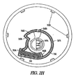
gauge 200, which corresponds to one or more embodiments of the invention. - Figure 2H
- is a bottom view of the upper cap and dial assembly portions of the
gauge 200, which corresponds to one or more embodiments of the invention. - This description, which incorporates the above-identified figures and appended claims, describes one or more specific inventive embodiments. These embodiments, offered not to limit but only to exemplify and teach the inventions, are shown and described in sufficient detail to enable those skilled in the art to implement or practice the invention. The description may use terms, such as upper or lower in reference to specific features of various as embodiments; however, unless included in the claims, such terms are merely to aid correlating the drawings with the written description. Moreover, where appropriate to avoid obscuring the invention, the description may omit certain information known to those of skill in the art.
-
Figure 1A shows a block diagram of anexemplary engine system 100 which incorporates teachings of the present invention.System 100 includes anengine 110, afuel filter 120, anair filter 130, and flow-restriction gauges (or indicators) 140 and 150. -
Engine 110 includes anair inlet 111 and afuel inlet 112 for respectively channeling air and fuel intoengine 110 for combustion according to known principles. In the exemplary embodiment,engine 110 takes the form of an internal combustion engine; however, in some embodiments,engine 110 takes other forms. -
Air filter 120 provides a filteredair flow 121 throughair inlet 111 toengine 110. In the exemplary embodiment,air filter 120 takes any convenient or desirable form. -
Fuel filter 130, which is in fluid communication withfuel inlet 112, provides a filteredair flow 131 throughinlet 112 toengine 110. In the exemplary embodiment,fuel filter 130 takes any convenient or desirable form. -
Flow restriction gauge 140, which is sized to measure flow-restriction based on a difference between vacuum pressure created byair flow 121 and atmospheric pressure, includes anexterior dial 141 for indicating a flow-restriction level. Similarly, gauge 150 is sized to measure flow-restriction based on a difference between vacuum pressure created byfuel flow 131 and atmospheric pressure, and includesexternal dial 151 andscale label 152. -
Figure 1B , a top view ofgauge 140, shows that in the exemplary embodiment, dial 141 includes adial pointer 141 A and thatgauge 140 further includesscale markings 142, resetmarkings 143, andlabel key 144, all of which may be embossed, molded, or engraved into a top surface ofgauge 140.Scale markings 142 denote three fluid-restriction levels: New, which corresponds to any restriction less than 75% of maximum allowable restriction (determined for engine 110); 75% of maximum allowable restriction; and Service, which indicates that the air filter should be replaced because it is restricting air flow at or beyond the maximum desirable restriction level. (Other embodiments may provide greater or lesser numbers of restriction levels and fluid-restriction thresholds other than 75%.) Indeed, some embodiments may even provide a continuous read out of flow restriction over all or a portion of the read out range. (The continuous readout can be achieved by using a rough surface on a ramped cam in combination with a sharp axial projection.) For example, one embodiment may provide continuous readout between the 75% and Service levels.) - Reset marking 143 indicates that
gauge 140 can be manually reset by rotatingdial 141 counterclockwise from the Service level back to the New level. And,label key 144 facilitates manual or automated alignment and attachment of an adhesive scale label, such aslabel 152 inFigure 1C . -
Label 152, which takes a generally circular shape, includes color scale region 152A and label mount key 152B. In the exemplary embodiment, color scale 152A includes a green sector which corresponds to flow-restriction levels that are less than a maximum allowable flow restriction and a red sector which corresponds to flow-restriction levels greater than the maximum allowable flow restriction. Some embodiments may include an intermediate yellow sector; moreover, some embodiments also include glow-in-the-dark graphics based on phosphorescence or chemicaluminescense materials, such as zinc sulfide or strontium aluminate without a radioactive element, such as radium. -
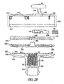
Figures 2A and2B respectively show a central cross-sectional view and an exploded central cross-sectional view of an exemplary flow-restriction gauge 200, which may be substituted forgauges 140 and 150 inFigure 1 .Gauge 200 includes a housing assembly 210, adiaphragm assembly 220, and a calibration spring 230, and adial assembly 240. - Housing assembly 210, which includes an
upper cap portion 212 and a lower housing orinlet portion 214.. In the exemplary embodiment, all components of the housing assembly are molded from an opaque material, such as nylon. - In particular,
upper cap portion 212, which in the exemplary embodiment has a generally right cylindrical cup- or pan-like structure, includes atop portion 212A, asidewall 212B,annular locking ledge 212C, spacer studs 212D, dial opening 212E, andcam pocket wall 212F. -
Top portion 212A, which includes scale markings or labels as shown inFigure 1B , is integrally molded withsidewall 212B.Sidewall 212B, which circumscribes the perimeter oftop portion 212A, extends downward vertically and terminates intoannular locking ledge 212C. Extending vertically downward from the underside oftop portion 212B are six spacer studs 212D distributed circumferentially around the interior joint betweentop portion 212A andsidewall 212B. - Cam pocket wall 212E also extends downwardly from the underside of
top portion 212A, defining peripheral shape and depth of a cam pocket (or recess) 213, shown best inFigure 2C . The height of the cam pocket wall 212E and the heights of spacer studs 212D, measured from the underside oftop portion 212A are substantially equal in the exemplary embodiment.Cam pocket 213 surrounds dial opening 212E intop portion 212A of housing assembly 210. -
Lower housing portion 214, which in the exemplary embodiment is integrally molded from a durable nylon, includes alower inlet portion 214A and an upper annular flange portion 214B. -
Lower inlet portion 214A includes exterior engagement features 214C, such as threads, ribs, or flanges, to facilitate fluid-tight coupling to an air or fuel inlet, such asinlet Figure 1A .Inlet portion 214A also includes an annular interior shelf 214D, and an upper circular rim orribs 214E. - Upper annular flange portion 214B extends outward circumferentially from an upper portion of
inlet portion 214A defining a shallow bowl region 214F. Anannular ledge 214G is spaced radially inward from an outer rim portion 214H of flange portion 214B, thereby defining anannular seat 2141. The outer rim portion engages in a snap fit withannular locking ledge 212C of the upper cap portion of the housing assembly. - In addition to housing assembly 210,
gauge 200 includescalibration spring 220, diaphragm 230, and dialassembly 240. -
Calibration spring 220 has alower portion 221 and anupper portion 222.Lower portion 221 rests on annular interior shelf 214D and theupper portion 222 extend upward into shallow bowl region 214F of flange portion 214B to contact diaphragm 230. - Diaphragm 230, also shown in the top perspective view of
Figure 2F , includes a rigid central disk portion 232 and a flexible outerannular portion 234. Central disk portion 232, which may be injection molded from a suitable plastic, includes a taperedaxial projection 232C. Flexible outer annular portion 232B, which is formed of silicon or other suitably resilient and substantially fluid impervious material and over-molded ontocentral disk portion 232A, includes an outerannular bead 232D. (At least one advantage of the over-mold configuration is that it reduces the mass of the diaphragm, which in combination with the spring constant of the calibration spring dramatically improves the ability of the gauge to avoid vibration- or shock-induced false triggering. However, in some embodiments, diaphragm 230 is made of a single material.) -
Annular bead 232D is sandwiched betweenlower inlet portion 214 of the housing assembly, specificallyannular seat 2141, and a lower rim 241A of circular plate 241 ofdial assembly 240. In this arrangement, the diaphragm defines and provides a generally fluid tight seal between a lower chamber 233 that is in fluid communication with inlet 11 or 112 (inFigure 1 ), and an upper chamber 235 that is fluid communication with the atmosphere via dial opening 212E. ('Generally fluid-tight,' as used herein, refers to a seal that has a leakage rate low enough to not interfere with the operation of the diaphragm and the flow-restriction gauge.) - In addition to circular plate 241,
dial assembly 240 further includes acam portion 242, ahelical spring 244, and adial 246. - Circular plate 241, which is shown in perspective in
Figure 2E , includes annular rim 241A and a central opening 241B. Annular rim 241A assists in sealing lower chamber 235 by engaging the outer annular bead of diaphragm under force transferred through spacing studs 212D ofupper housing cap 212. Central opening 241B allows taperedaxial projection 232C (of diaphragm 230) to extend through an engage or disengage fromcam portion 242. -
Cam portion 242, which is shown most completely in the perspective view ofFigure 2D , includes a dial-mount opening 242A, aspring mounting post 242B, a notch 242C, and a step 242D. Dial-mount opening 242A engages in a snap fit with twoprongs 246A that extend from the underside ofdial 246, thereby securingcam portion 242 withincam pocket 213.Spring mounting post 242B fits within one end ofhelical spring 244 and the other end of the spring fits withinspring nook 213A ofcam pocket 213. The spring biases rotation of the cam portion towardaxial projection 232C of diaphragm 232. - Notch 242C engages with axial projection 232 when
dial 246 is turned to a reset position. As diaphragm 230 flexes downward against the calibration spring in response to a vacuum created by a fluid flow exiting a filter,axial projection 232C moves downward in unison. Over time the filter restriction increases the vacuum sufficiently to draw the diaphragm and the projection down past the edge of notch 242C, allowing the cam to rotate under the force of spring 244 (best depicted inFigure 2F ) and engaging step 242D with the projection.Dial 246, which in some embodiments includes a glow-in-the-dark material, rotates in unison with the cam portion, and thus indicates, for example, a flow-restriction of 75%. Further restriction of flow through the filter increases the vacuum and continues to draw the projection downward, eventually disengaging it from step 242D and allowing the cam to rotate to its rest position, with the notch 242C against astop portion 213B ofcam pocket 213. - In furtherance of the art, the present inventors have presented, among other things, an exemplary flow-restriction gauge. The exemplary gauge has eight total parts, nine if the optional adhesive scale label is included. The exemplary gauge promises not only to be easily manufactured and assembled with considerable savings over conventional dial-type flow-restriction gauges, but also to provide reliable and consistent operation over a wide temperature range.
Claims (6)
- A flow-restriction gauge (140, 150, 200) for use with internal combustion engines, the gauge comprising:a housing assembly (210) including an upper cap portion (212) and a lower inlet portion (214), the upper cap portion having an opening (212E), an exterior surface surrounding the opening, and an interior surface opposite the exterior surface, with the interior surface having a pocket region (213) surrounding the opening;a cam (242) positioned within the pocket region to rotate about an axis generally perpendicular to the interior surface, the cam having at least one step;a helical spring (244) positioned within the pocket region longitudinally against the interior surface, and having one end mounted to a portion (242B) of the cam and another end mounted to a portion (213A) of the pocket region; anda dial pointer (246) positioned on the exterior surface of the upper cap portion and coupled to the cam to rotate in response to a vacuum in fluid communication with the lower inlet portion of the housing assembly.
- The flow-restriction gauge of claim 1, wherein the exterior surface of the upper cap portion includes a flow-restriction scale (142) integrally molded therewith.
- The flow-restriction gauge of claim 1, wherein the upper cap portion and the lower cap portion are opaque and snapped together.
- The flow-restriction gauge of claim 1, further including a label (152) having at least one flow-restriction level, the label adhered to the exterior surface of the upper cap portion.
- The flow-restriction gauge of claim 1, further comprising:a diaphragm (230) within an interior of the housing assembly (210) between the upper cap portion and the lower inlet portion, the diaphragm having a deflectable portion and (234) an axial projection (232C);a plate (241) within the interior of the housing assembly between the pocket region of the upper cap portion and the diaphragm and having an opening (241B) through which the axial projection engages the cam.
- The flow-restriction gauge of claim 5:wherein the lower inlet portion of the housing assembly includes:an inlet (214A) defining an axial passage for allowing fluid communication between the diaphragm and a fluid line, the passage having a passage restriction (214D) between the diaphragm and fluid line;an upper flange portion (214B) extending from an upper portion of the inlet and having an outer annular portion (214H) in a snap fit with an interior ledge (212C) of the upper cap portion, the diaphragm sandwiched between the outer annular portion and the plate;wherein the gauge further comprises a helical calibration spring (220) within the passage, the spring having a lower end (221) resting on the passage restriction and an upper end (222) contacting the diaphragm.
Applications Claiming Priority (2)
| Application Number | Priority Date | Filing Date | Title |
|---|---|---|---|
| US81423306P | 2006-06-16 | 2006-06-16 | |
| PCT/US2007/014294 WO2007149445A1 (en) | 2006-06-16 | 2007-06-18 | Dial-type flow-restriction gauges |
Publications (2)
| Publication Number | Publication Date |
|---|---|
| EP2029255A1 EP2029255A1 (en) | 2009-03-04 |
| EP2029255B1 true EP2029255B1 (en) | 2011-10-26 |
Family
ID=38626498
Family Applications (1)
| Application Number | Title | Priority Date | Filing Date |
|---|---|---|---|
| EP07796265A Not-in-force EP2029255B1 (en) | 2006-06-16 | 2007-06-18 | Dial-type flow-restriction gauges |
Country Status (4)
| Country | Link |
|---|---|
| US (2) | US7562579B2 (en) |
| EP (1) | EP2029255B1 (en) |
| JP (1) | JP2009541714A (en) |
| WO (1) | WO2007149445A1 (en) |
Families Citing this family (7)
| Publication number | Priority date | Publication date | Assignee | Title |
|---|---|---|---|---|
| US7470360B2 (en) * | 2005-01-21 | 2008-12-30 | Engineered Products Company | Fluid flow restriction indicator |
| EP2029255B1 (en) | 2006-06-16 | 2011-10-26 | Engineered Products Co. | Dial-type flow-restriction gauges |
| US10638630B2 (en) | 2012-12-21 | 2020-04-28 | Nathan R. Roberts | Storage and charging station system for portable electronic devices with side access to power distribution components |
| US9080897B2 (en) | 2013-02-22 | 2015-07-14 | Rosemount Inc. | Self-powered optical detector for mechanical gauge instruments |
| DE102016200699B4 (en) * | 2016-01-20 | 2025-12-04 | Robert Bosch Gmbh | Manufacturing process for a detection device and detection devices |
| US11766729B2 (en) * | 2017-09-28 | 2023-09-26 | International Business Machines Corporation | Molten solder injection head with vacuum filter and differential gauge system |
| EP4074404B1 (en) * | 2017-10-24 | 2025-09-03 | Donaldson Company, Inc. | Air cleaner assembly with restriction indicator |
Citations (1)
| Publication number | Priority date | Publication date | Assignee | Title |
|---|---|---|---|---|
| US20060042392A1 (en) * | 2004-08-31 | 2006-03-02 | Stanadyne Corporation | Filter change indicator |
Family Cites Families (35)
| Publication number | Priority date | Publication date | Assignee | Title |
|---|---|---|---|---|
| US3119367A (en) * | 1958-10-15 | 1964-01-28 | Bendix Corp | Visible filter clogging indicator |
| US3027865A (en) * | 1959-01-06 | 1962-04-03 | Honeywell Regulator Co | Clogged filter indicator |
| US3066527A (en) * | 1959-11-20 | 1962-12-04 | Bacharach Ind Instr Company | Air filter gauge |
| GB929085A (en) | 1960-03-18 | 1963-06-19 | Cooper S Mechanical Joints Ltd | Improvements in or relating to pressure operated visual warning devices |
| US3011470A (en) * | 1960-03-18 | 1961-12-05 | Thompson Ramo Wooldridge Inc | Pressure change indicator |
| US3388682A (en) * | 1965-03-04 | 1968-06-18 | Michigan Dynamics Inc | Vacuum responsive device |
| US3312187A (en) * | 1966-02-02 | 1967-04-04 | Ford Motor Co | Fluid filter assembly having a warning indicator |
| US3487929A (en) * | 1967-05-29 | 1970-01-06 | Aero Flow Dynamics Inc | Mechanical-type filter bypass indicator |
| US3381651A (en) * | 1967-05-31 | 1968-05-07 | Ford Motor Co | Fluid filter assembly having a warning indicator |
| US3690318A (en) * | 1970-04-16 | 1972-09-12 | Bourns Inc | Apparatus for parenteral fluid infusion provided with variable flow control means |
| US3639998A (en) * | 1970-05-21 | 1972-02-08 | Whirlpool Co | Filter condition indicator |
| US3686835A (en) * | 1970-11-27 | 1972-08-29 | Mine Safety Appliances Co | Filter cassette with removable capsule |
| GB1407125A (en) * | 1973-02-22 | 1975-09-24 | Gen Motors Ltd | Pressure responsive visual warning devices |
| DE2404452C2 (en) | 1974-01-31 | 1984-09-06 | Hans 8221 Vachendorf Kern | Display device for the degree of contamination of a filter |
| US4033733A (en) * | 1976-02-23 | 1977-07-05 | Joseph N. Nelson | Air filter gauge |
| DE2616315C3 (en) | 1976-04-14 | 1980-05-29 | Char-Shin Lee | Pressure gauge |
| US4445456A (en) * | 1978-06-19 | 1984-05-01 | Engineered Products Company | Air filter restriction indicating device |
| US4162660A (en) * | 1978-06-29 | 1979-07-31 | Albertson Robert V | Dirty air filter indicator |
| US4369728A (en) * | 1981-02-09 | 1983-01-25 | Engineered Products Company | Air filter restriction indicating device |
| DE3428307A1 (en) | 1984-08-01 | 1986-02-13 | Filterwerk Mann & Hummel Gmbh, 7140 Ludwigsburg | DISPLAY DEVICE FOR THE POLLUTION LEVEL OF SUCTION AIR FILTERS |
| US4620500A (en) * | 1985-08-12 | 1986-11-04 | Condon James R | Pressure loss indicator |
| DE3544492C1 (en) | 1985-12-17 | 1987-01-02 | Mann & Hummel Filter | Indicator for the degree of contamination of intake air filters |
| US4726823A (en) * | 1987-03-03 | 1988-02-23 | Brice Patrick J | Movable filter assembly for automotive air handling assembly |
| US5325707A (en) * | 1993-03-08 | 1994-07-05 | Slater Harry F | Air filter condition indicator |
| US5845597A (en) * | 1994-03-15 | 1998-12-08 | Vista Water Systems, Inc. | Separation medium efficiency indicator |
| US5850183A (en) * | 1995-02-24 | 1998-12-15 | Engineered Products Co. | Air filter restriction indicating device |
| AU709849B2 (en) * | 1995-08-04 | 1999-09-09 | Donaldson Company Inc. | Restriction indicator for air cleaners |
| US5616157A (en) * | 1995-11-14 | 1997-04-01 | Florida Pneumatic Manufacturing Co. | Visible restricted filter indicator |
| US5753821A (en) * | 1997-01-02 | 1998-05-19 | Chin Ray Industrial Co., Ltd. | Single diaphragm pressure gauge with uniform thickness gauge frame |
| US6327902B1 (en) * | 1999-06-25 | 2001-12-11 | Engineered Products Company | Air filter restriction indicator gauge |
| AU6633600A (en) * | 1999-08-16 | 2001-03-13 | Donaldson Company Inc. | Restriction indicator |
| DE10315052A1 (en) | 2002-04-03 | 2003-12-11 | Kyosan Denki Kk | Fuel supply system has diesel filter with filtering device accommodated in housing, and displacement registering sensor set to predetermined range and installed on outflow side of filtering device |
| US7470360B2 (en) | 2005-01-21 | 2008-12-30 | Engineered Products Company | Fluid flow restriction indicator |
| WO2006081564A1 (en) | 2005-01-28 | 2006-08-03 | Engineered Products Company | Non-locking switch for filter monitoring |
| EP2029255B1 (en) | 2006-06-16 | 2011-10-26 | Engineered Products Co. | Dial-type flow-restriction gauges |
-
2007
- 2007-06-18 EP EP07796265A patent/EP2029255B1/en not_active Not-in-force
- 2007-06-18 US US11/764,747 patent/US7562579B2/en active Active
- 2007-06-18 WO PCT/US2007/014294 patent/WO2007149445A1/en not_active Ceased
- 2007-06-18 JP JP2009515537A patent/JP2009541714A/en not_active Withdrawn
-
2009
- 2009-04-17 US US12/425,761 patent/US7921720B2/en not_active Expired - Fee Related
Patent Citations (1)
| Publication number | Priority date | Publication date | Assignee | Title |
|---|---|---|---|---|
| US20060042392A1 (en) * | 2004-08-31 | 2006-03-02 | Stanadyne Corporation | Filter change indicator |
Also Published As
| Publication number | Publication date |
|---|---|
| EP2029255A1 (en) | 2009-03-04 |
| WO2007149445A9 (en) | 2008-04-10 |
| US20090199645A1 (en) | 2009-08-13 |
| WO2007149445A1 (en) | 2007-12-27 |
| US7562579B2 (en) | 2009-07-21 |
| US20080072687A1 (en) | 2008-03-27 |
| JP2009541714A (en) | 2009-11-26 |
| US7921720B2 (en) | 2011-04-12 |
Similar Documents
| Publication | Publication Date | Title |
|---|---|---|
| US7921720B2 (en) | Dial-type flow-restriction gauges | |
| US4445456A (en) | Air filter restriction indicating device | |
| US4369728A (en) | Air filter restriction indicating device | |
| KR100950598B1 (en) | Gas discharge valve | |
| US7990275B1 (en) | Fuel tank pressure indicator, including cap and container interface pressure indicator | |
| US12030009B1 (en) | Air cleaner assembly with restriction indicator | |
| EP1506889B1 (en) | Mounting a fuel vapor management valve internally to a fuel tank | |
| US4254731A (en) | Filter restriction indicator | |
| WO2008027347A2 (en) | Filter pressure indicator | |
| US6531960B1 (en) | Low tire pressure indicator | |
| CN110892241B (en) | engine monitoring | |
| US3916817A (en) | Pressure responsive visual warning devices | |
| CN1192799A (en) | Restriction indicator for air cleaner | |
| EP1736661A2 (en) | Single position indicator gauge | |
| JP2007532815A (en) | Fuel filter clogging indicator device for internal combustion engines, especially diesel engines | |
| US5569849A (en) | Visual tire cap pressure gauge | |
| CN110799742B (en) | Engine monitoring | |
| CN108331688A (en) | fuel filter | |
| EP1192350B1 (en) | Fuel filter gauge | |
| EP1838411A1 (en) | Fluid flow restriction indicator | |
| US3983894A (en) | Fluid valves | |
| US3528291A (en) | Liquid level indicator | |
| WO1999025974A1 (en) | Restriction indicator for air cleaners | |
| CA1106705A (en) | Air filter restriction indicating device | |
| WO2018191240A1 (en) | Vapor pressure sensor assembly |
Legal Events
| Date | Code | Title | Description |
|---|---|---|---|
| PUAI | Public reference made under article 153(3) epc to a published international application that has entered the european phase |
Free format text: ORIGINAL CODE: 0009012 |
|
| 17P | Request for examination filed |
Effective date: 20081120 |
|
| AK | Designated contracting states |
Kind code of ref document: A1 Designated state(s): AT BE BG CH CY CZ DE DK EE ES FI FR GB GR HU IE IS IT LI LT LU LV MC MT NL PL PT RO SE SI SK TR |
|
| AX | Request for extension of the european patent |
Extension state: AL BA HR MK RS |
|
| 17Q | First examination report despatched |
Effective date: 20090331 |
|
| DAX | Request for extension of the european patent (deleted) | ||
| RBV | Designated contracting states (corrected) |
Designated state(s): DE FR GB IT |
|
| GRAP | Despatch of communication of intention to grant a patent |
Free format text: ORIGINAL CODE: EPIDOSNIGR1 |
|
| GRAS | Grant fee paid |
Free format text: ORIGINAL CODE: EPIDOSNIGR3 |
|
| GRAA | (expected) grant |
Free format text: ORIGINAL CODE: 0009210 |
|
| AK | Designated contracting states |
Kind code of ref document: B1 Designated state(s): DE FR GB IT |
|
| REG | Reference to a national code |
Ref country code: GB Ref legal event code: FG4D |
|
| REG | Reference to a national code |
Ref country code: DE Ref legal event code: R096 Ref document number: 602007018288 Country of ref document: DE Effective date: 20120105 |
|
| PG25 | Lapsed in a contracting state [announced via postgrant information from national office to epo] |
Ref country code: IT Free format text: LAPSE BECAUSE OF FAILURE TO SUBMIT A TRANSLATION OF THE DESCRIPTION OR TO PAY THE FEE WITHIN THE PRESCRIBED TIME-LIMIT Effective date: 20111026 |
|
| PLBE | No opposition filed within time limit |
Free format text: ORIGINAL CODE: 0009261 |
|
| STAA | Information on the status of an ep patent application or granted ep patent |
Free format text: STATUS: NO OPPOSITION FILED WITHIN TIME LIMIT |
|
| 26N | No opposition filed |
Effective date: 20120727 |
|
| REG | Reference to a national code |
Ref country code: DE Ref legal event code: R097 Ref document number: 602007018288 Country of ref document: DE Effective date: 20120727 |
|
| REG | Reference to a national code |
Ref country code: FR Ref legal event code: ST Effective date: 20130228 |
|
| PG25 | Lapsed in a contracting state [announced via postgrant information from national office to epo] |
Ref country code: FR Free format text: LAPSE BECAUSE OF NON-PAYMENT OF DUE FEES Effective date: 20120702 |
|
| REG | Reference to a national code |
Ref country code: DE Ref legal event code: R082 Ref document number: 602007018288 Country of ref document: DE Representative=s name: ADVOTEC. PATENT- UND RECHTSANWAELTE, DE Ref country code: DE Ref legal event code: R081 Ref document number: 602007018288 Country of ref document: DE Owner name: DONALDSON COMPANY, INC. (N.D.GES.D. STAATES DE, US Free format text: FORMER OWNER: ENGINEERED PRODUCTS CO., WATERLOO, IA., US |
|
| REG | Reference to a national code |
Ref country code: GB Ref legal event code: 732E Free format text: REGISTERED BETWEEN 20170504 AND 20170510 |
|
| PGFP | Annual fee paid to national office [announced via postgrant information from national office to epo] |
Ref country code: GB Payment date: 20170627 Year of fee payment: 11 |
|
| PGFP | Annual fee paid to national office [announced via postgrant information from national office to epo] |
Ref country code: DE Payment date: 20170628 Year of fee payment: 11 |
|
| REG | Reference to a national code |
Ref country code: DE Ref legal event code: R119 Ref document number: 602007018288 Country of ref document: DE |
|
| GBPC | Gb: european patent ceased through non-payment of renewal fee |
Effective date: 20180618 |
|
| PG25 | Lapsed in a contracting state [announced via postgrant information from national office to epo] |
Ref country code: GB Free format text: LAPSE BECAUSE OF NON-PAYMENT OF DUE FEES Effective date: 20180618 Ref country code: DE Free format text: LAPSE BECAUSE OF NON-PAYMENT OF DUE FEES Effective date: 20190101 |
|
| P01 | Opt-out of the competence of the unified patent court (upc) registered |
Effective date: 20230411 |