EP2029040B1 - Wire guide sphincterotome - Google Patents
Wire guide sphincterotome Download PDFInfo
- Publication number
- EP2029040B1 EP2029040B1 EP07795999.7A EP07795999A EP2029040B1 EP 2029040 B1 EP2029040 B1 EP 2029040B1 EP 07795999 A EP07795999 A EP 07795999A EP 2029040 B1 EP2029040 B1 EP 2029040B1
- Authority
- EP
- European Patent Office
- Prior art keywords
- wire guide
- cutting
- cutting portion
- medical system
- sheath
- Prior art date
- Legal status (The legal status is an assumption and is not a legal conclusion. Google has not performed a legal analysis and makes no representation as to the accuracy of the status listed.)
- Not-in-force
Links
- 208000031481 Pathologic Constriction Diseases 0.000 claims description 21
- 239000000463 material Substances 0.000 claims description 12
- -1 polytetrafluoroethylene Polymers 0.000 claims description 6
- 229920001343 polytetrafluoroethylene Polymers 0.000 claims description 2
- 239000004810 polytetrafluoroethylene Substances 0.000 claims description 2
- BASFCYQUMIYNBI-UHFFFAOYSA-N platinum Chemical compound [Pt] BASFCYQUMIYNBI-UHFFFAOYSA-N 0.000 description 10
- 238000000034 method Methods 0.000 description 8
- 210000005070 sphincter Anatomy 0.000 description 7
- 210000003445 biliary tract Anatomy 0.000 description 6
- 229910052751 metal Inorganic materials 0.000 description 5
- 239000002184 metal Substances 0.000 description 5
- 229910045601 alloy Inorganic materials 0.000 description 4
- 239000000956 alloy Substances 0.000 description 4
- 238000007459 endoscopic retrograde cholangiopancreatography Methods 0.000 description 4
- 150000002739 metals Chemical class 0.000 description 4
- 229910052697 platinum Inorganic materials 0.000 description 4
- WFKWXMTUELFFGS-UHFFFAOYSA-N tungsten Chemical compound [W] WFKWXMTUELFFGS-UHFFFAOYSA-N 0.000 description 4
- 229910052721 tungsten Inorganic materials 0.000 description 4
- 239000010937 tungsten Substances 0.000 description 4
- 210000004141 ampulla of vater Anatomy 0.000 description 3
- PCHJSUWPFVWCPO-UHFFFAOYSA-N gold Chemical compound [Au] PCHJSUWPFVWCPO-UHFFFAOYSA-N 0.000 description 3
- 229910052737 gold Inorganic materials 0.000 description 3
- 239000010931 gold Substances 0.000 description 3
- 208000014674 injury Diseases 0.000 description 3
- 210000000277 pancreatic duct Anatomy 0.000 description 3
- 229920000642 polymer Polymers 0.000 description 3
- 210000004514 sphincter of oddi Anatomy 0.000 description 3
- 229910052715 tantalum Inorganic materials 0.000 description 3
- GUVRBAGPIYLISA-UHFFFAOYSA-N tantalum atom Chemical compound [Ta] GUVRBAGPIYLISA-UHFFFAOYSA-N 0.000 description 3
- 230000008733 trauma Effects 0.000 description 3
- KDLHZDBZIXYQEI-UHFFFAOYSA-N Palladium Chemical compound [Pd] KDLHZDBZIXYQEI-UHFFFAOYSA-N 0.000 description 2
- 239000004698 Polyethylene Substances 0.000 description 2
- BQCADISMDOOEFD-UHFFFAOYSA-N Silver Chemical compound [Ag] BQCADISMDOOEFD-UHFFFAOYSA-N 0.000 description 2
- TZCXTZWJZNENPQ-UHFFFAOYSA-L barium sulfate Chemical compound [Ba+2].[O-]S([O-])(=O)=O TZCXTZWJZNENPQ-UHFFFAOYSA-L 0.000 description 2
- 238000002347 injection Methods 0.000 description 2
- 239000007924 injection Substances 0.000 description 2
- 229910052741 iridium Inorganic materials 0.000 description 2
- GKOZUEZYRPOHIO-UHFFFAOYSA-N iridium atom Chemical compound [Ir] GKOZUEZYRPOHIO-UHFFFAOYSA-N 0.000 description 2
- 238000004519 manufacturing process Methods 0.000 description 2
- 239000004417 polycarbonate Substances 0.000 description 2
- 229920000573 polyethylene Polymers 0.000 description 2
- 229920001296 polysiloxane Polymers 0.000 description 2
- 229920002635 polyurethane Polymers 0.000 description 2
- 239000004814 polyurethane Substances 0.000 description 2
- 229910052703 rhodium Inorganic materials 0.000 description 2
- 239000010948 rhodium Substances 0.000 description 2
- MHOVAHRLVXNVSD-UHFFFAOYSA-N rhodium atom Chemical compound [Rh] MHOVAHRLVXNVSD-UHFFFAOYSA-N 0.000 description 2
- 229910052709 silver Inorganic materials 0.000 description 2
- 239000004332 silver Substances 0.000 description 2
- ZCYVEMRRCGMTRW-UHFFFAOYSA-N 7553-56-2 Chemical compound [I] ZCYVEMRRCGMTRW-UHFFFAOYSA-N 0.000 description 1
- 229910000014 Bismuth subcarbonate Inorganic materials 0.000 description 1
- 206010013832 Duodenal perforation Diseases 0.000 description 1
- 208000032843 Hemorrhage Diseases 0.000 description 1
- 206010028980 Neoplasm Diseases 0.000 description 1
- 239000000020 Nitrocellulose Substances 0.000 description 1
- 239000004677 Nylon Substances 0.000 description 1
- 206010033645 Pancreatitis Diseases 0.000 description 1
- 206010033647 Pancreatitis acute Diseases 0.000 description 1
- 239000004952 Polyamide Substances 0.000 description 1
- 229920002732 Polyanhydride Polymers 0.000 description 1
- 229920002614 Polyether block amide Polymers 0.000 description 1
- 239000004642 Polyimide Substances 0.000 description 1
- 229920001710 Polyorthoester Polymers 0.000 description 1
- 239000004743 Polypropylene Substances 0.000 description 1
- 229910001260 Pt alloy Inorganic materials 0.000 description 1
- 229910001080 W alloy Inorganic materials 0.000 description 1
- MCMNRKCIXSYSNV-UHFFFAOYSA-N ZrO2 Inorganic materials O=[Zr]=O MCMNRKCIXSYSNV-UHFFFAOYSA-N 0.000 description 1
- FJWGYAHXMCUOOM-QHOUIDNNSA-N [(2s,3r,4s,5r,6r)-2-[(2r,3r,4s,5r,6s)-4,5-dinitrooxy-2-(nitrooxymethyl)-6-[(2r,3r,4s,5r,6s)-4,5,6-trinitrooxy-2-(nitrooxymethyl)oxan-3-yl]oxyoxan-3-yl]oxy-3,5-dinitrooxy-6-(nitrooxymethyl)oxan-4-yl] nitrate Chemical compound O([C@@H]1O[C@@H]([C@H]([C@H](O[N+]([O-])=O)[C@H]1O[N+]([O-])=O)O[C@H]1[C@@H]([C@@H](O[N+]([O-])=O)[C@H](O[N+]([O-])=O)[C@@H](CO[N+]([O-])=O)O1)O[N+]([O-])=O)CO[N+](=O)[O-])[C@@H]1[C@@H](CO[N+]([O-])=O)O[C@@H](O[N+]([O-])=O)[C@H](O[N+]([O-])=O)[C@H]1O[N+]([O-])=O FJWGYAHXMCUOOM-QHOUIDNNSA-N 0.000 description 1
- 230000002159 abnormal effect Effects 0.000 description 1
- 239000004676 acrylonitrile butadiene styrene Substances 0.000 description 1
- 201000003229 acute pancreatitis Diseases 0.000 description 1
- 210000003484 anatomy Anatomy 0.000 description 1
- 230000000845 anti-microbial effect Effects 0.000 description 1
- 210000000013 bile duct Anatomy 0.000 description 1
- 229910052797 bismuth Inorganic materials 0.000 description 1
- JCXGWMGPZLAOME-UHFFFAOYSA-N bismuth atom Chemical compound [Bi] JCXGWMGPZLAOME-UHFFFAOYSA-N 0.000 description 1
- MGLUJXPJRXTKJM-UHFFFAOYSA-L bismuth subcarbonate Chemical compound O=[Bi]OC(=O)O[Bi]=O MGLUJXPJRXTKJM-UHFFFAOYSA-L 0.000 description 1
- 229940036358 bismuth subcarbonate Drugs 0.000 description 1
- 208000034158 bleeding Diseases 0.000 description 1
- 230000000740 bleeding effect Effects 0.000 description 1
- 229910052793 cadmium Inorganic materials 0.000 description 1
- BDOSMKKIYDKNTQ-UHFFFAOYSA-N cadmium atom Chemical compound [Cd] BDOSMKKIYDKNTQ-UHFFFAOYSA-N 0.000 description 1
- 229920002301 cellulose acetate Polymers 0.000 description 1
- 208000003167 cholangitis Diseases 0.000 description 1
- 239000000788 chromium alloy Substances 0.000 description 1
- 210000001953 common bile duct Anatomy 0.000 description 1
- 210000003459 common hepatic duct Anatomy 0.000 description 1
- 239000012141 concentrate Substances 0.000 description 1
- 239000000994 contrast dye Substances 0.000 description 1
- 239000002872 contrast media Substances 0.000 description 1
- 229940039231 contrast media Drugs 0.000 description 1
- 238000007796 conventional method Methods 0.000 description 1
- 230000003247 decreasing effect Effects 0.000 description 1
- 201000010099 disease Diseases 0.000 description 1
- 208000037265 diseases, disorders, signs and symptoms Diseases 0.000 description 1
- 238000001839 endoscopy Methods 0.000 description 1
- 239000004811 fluoropolymer Substances 0.000 description 1
- 229920002313 fluoropolymer Polymers 0.000 description 1
- 238000002594 fluoroscopy Methods 0.000 description 1
- 230000004927 fusion Effects 0.000 description 1
- 229920001903 high density polyethylene Polymers 0.000 description 1
- 239000004700 high-density polyethylene Substances 0.000 description 1
- 229910001026 inconel Inorganic materials 0.000 description 1
- 239000011810 insulating material Substances 0.000 description 1
- 238000009413 insulation Methods 0.000 description 1
- 229910052740 iodine Inorganic materials 0.000 description 1
- 239000011630 iodine Substances 0.000 description 1
- 210000004185 liver Anatomy 0.000 description 1
- 239000003550 marker Substances 0.000 description 1
- 238000002324 minimally invasive surgery Methods 0.000 description 1
- 239000000203 mixture Substances 0.000 description 1
- HLXZNVUGXRDIFK-UHFFFAOYSA-N nickel titanium Chemical compound [Ti].[Ti].[Ti].[Ti].[Ti].[Ti].[Ti].[Ti].[Ti].[Ti].[Ti].[Ni].[Ni].[Ni].[Ni].[Ni].[Ni].[Ni].[Ni].[Ni].[Ni].[Ni].[Ni].[Ni].[Ni] HLXZNVUGXRDIFK-UHFFFAOYSA-N 0.000 description 1
- 229910001000 nickel titanium Inorganic materials 0.000 description 1
- 229920001220 nitrocellulos Polymers 0.000 description 1
- 229920001778 nylon Polymers 0.000 description 1
- RVTZCBVAJQQJTK-UHFFFAOYSA-N oxygen(2-);zirconium(4+) Chemical compound [O-2].[O-2].[Zr+4] RVTZCBVAJQQJTK-UHFFFAOYSA-N 0.000 description 1
- 229910052763 palladium Inorganic materials 0.000 description 1
- 239000002745 poly(ortho ester) Substances 0.000 description 1
- 229920002647 polyamide Polymers 0.000 description 1
- 229920000515 polycarbonate Polymers 0.000 description 1
- 229920000728 polyester Polymers 0.000 description 1
- 229920001721 polyimide Polymers 0.000 description 1
- 229920001155 polypropylene Polymers 0.000 description 1
- 239000004800 polyvinyl chloride Substances 0.000 description 1
- 229910052702 rhenium Inorganic materials 0.000 description 1
- WUAPFZMCVAUBPE-UHFFFAOYSA-N rhenium atom Chemical compound [Re] WUAPFZMCVAUBPE-UHFFFAOYSA-N 0.000 description 1
- 229910001220 stainless steel Inorganic materials 0.000 description 1
- 239000010935 stainless steel Substances 0.000 description 1
- 239000004575 stone Substances 0.000 description 1
- 238000001356 surgical procedure Methods 0.000 description 1
- 230000001225 therapeutic effect Effects 0.000 description 1
- 230000003144 traumatizing effect Effects 0.000 description 1
Images


Classifications
-
- A—HUMAN NECESSITIES
- A61—MEDICAL OR VETERINARY SCIENCE; HYGIENE
- A61B—DIAGNOSIS; SURGERY; IDENTIFICATION
- A61B18/00—Surgical instruments, devices or methods for transferring non-mechanical forms of energy to or from the body
- A61B18/04—Surgical instruments, devices or methods for transferring non-mechanical forms of energy to or from the body by heating
- A61B18/12—Surgical instruments, devices or methods for transferring non-mechanical forms of energy to or from the body by heating by passing a current through the tissue to be heated, e.g. high-frequency current
- A61B18/14—Probes or electrodes therefor
- A61B18/1492—Probes or electrodes therefor having a flexible, catheter-like structure, e.g. for heart ablation
-
- A—HUMAN NECESSITIES
- A61—MEDICAL OR VETERINARY SCIENCE; HYGIENE
- A61B—DIAGNOSIS; SURGERY; IDENTIFICATION
- A61B18/00—Surgical instruments, devices or methods for transferring non-mechanical forms of energy to or from the body
- A61B2018/00571—Surgical instruments, devices or methods for transferring non-mechanical forms of energy to or from the body for achieving a particular surgical effect
- A61B2018/00601—Cutting
-
- A—HUMAN NECESSITIES
- A61—MEDICAL OR VETERINARY SCIENCE; HYGIENE
- A61B—DIAGNOSIS; SURGERY; IDENTIFICATION
- A61B18/00—Surgical instruments, devices or methods for transferring non-mechanical forms of energy to or from the body
- A61B18/04—Surgical instruments, devices or methods for transferring non-mechanical forms of energy to or from the body by heating
- A61B18/12—Surgical instruments, devices or methods for transferring non-mechanical forms of energy to or from the body by heating by passing a current through the tissue to be heated, e.g. high-frequency current
- A61B18/14—Probes or electrodes therefor
- A61B2018/1405—Electrodes having a specific shape
- A61B2018/1407—Loop
-
- A—HUMAN NECESSITIES
- A61—MEDICAL OR VETERINARY SCIENCE; HYGIENE
- A61B—DIAGNOSIS; SURGERY; IDENTIFICATION
- A61B18/00—Surgical instruments, devices or methods for transferring non-mechanical forms of energy to or from the body
- A61B18/04—Surgical instruments, devices or methods for transferring non-mechanical forms of energy to or from the body by heating
- A61B18/12—Surgical instruments, devices or methods for transferring non-mechanical forms of energy to or from the body by heating by passing a current through the tissue to be heated, e.g. high-frequency current
- A61B18/14—Probes or electrodes therefor
- A61B2018/1405—Electrodes having a specific shape
- A61B2018/144—Wire
-
- A—HUMAN NECESSITIES
- A61—MEDICAL OR VETERINARY SCIENCE; HYGIENE
- A61B—DIAGNOSIS; SURGERY; IDENTIFICATION
- A61B18/00—Surgical instruments, devices or methods for transferring non-mechanical forms of energy to or from the body
- A61B18/04—Surgical instruments, devices or methods for transferring non-mechanical forms of energy to or from the body by heating
- A61B18/12—Surgical instruments, devices or methods for transferring non-mechanical forms of energy to or from the body by heating by passing a current through the tissue to be heated, e.g. high-frequency current
- A61B18/14—Probes or electrodes therefor
- A61B2018/1475—Electrodes retractable in or deployable from a housing
Definitions
- the present invention relates to medical devices, and more particularly to medical devices, such as sphincterotomes and wire guides, used in surgical procedures.
- Medical devices such as catheters delivered over wire guides, are used in the pancreatobiliary system for endoscopic or other minimally invasive surgery.
- an Endoscopic Retrograde Cholangiopancreatography (ERCP) procedure is performed when the Sphincter of Oddi becomes constricted due to disease or trauma by introducing a catheter device from a duodenoscope through the ampullary orifice (Papilla of Vater) and into the biliary tree, which includes the bile duct, pancreatic duct and hepatic ducts of the liver.
- ERCP Endoscopic Retrograde Cholangiopancreatography
- a wire guide is first introduced into the biliary tree and the cannulation device, which is usually a sphincterotome/papllitome or ECRP catheter, is introduced over the wire guide and into the biliary tree to perform a first operation, which could be diagnostic in nature, such as injecting contrast media, or for therapeutic purposes, such as enlarging the ampullary orifice.
- a first operation which could be diagnostic in nature, such as injecting contrast media, or for therapeutic purposes, such as enlarging the ampullary orifice.
- Introducing the wire guide prior to or at the same time as the sphincterotome allows for cannulation of closed sphincters and other strictures due to the smaller diameter of the wire guide as compared to the sphincterotome.
- the sphincterotome may be used both to cannulate the ductal system and to enlarge the opening by delivery of electrical current to a bowed cutting wire at the distal end of the sphincterotome.
- Exemplary sphincterotomes typically include at least two lumens extending through the shaft thereof. One lumen is provided for an operating wire that is connected to the cutting wire and the other lumen is provided for the wire guide. Accordingly, typical sphincterotomes have a relatively large cross-section - much larger than a typical wire guide.
- the wire guide is usually left in place while the sphincterotome is advanced, operated and then removed.
- the wire guide can be used to provide subsequent access for other devices when additional medical procedures are performed, such as to remove a stone, to open a stricture, or to sample tissue.
- Complications are associated with the ERCP procedure and accessing the papilla of the pancreatic duct with the known medical devices described above, particularly multi-lumen sphincterotomes having a relatively large cross-section.
- Complications include acute pancreatitis, bleeding, duodenal perforation, cholangitis, etc. generally due to mechanical and thermal trauma of the papilla. Although complication rates are generally low, decreasing trauma to the papilla will help further lower the complication rates.
- the present invention provides a wire guide adapted to cannulate a stricture without requiring a separate device, such as a sphincterotome having a cutting wire, to perform the procedure.
- the present invention also provides a single lumen catheter suitable for use with the wire guide of the present invention.
- a medical system configured for cannulation of a lumen having a stricture.
- the medical system includes an elongate sheath having a proximal portion, a distal portion and a first lumen at least partially extending through the sheath.
- the medical system also includes a wire guide having a cutting portion, a non-cutting tip portion and a non-cutting shaft portion proximal to the cutting portion.
- the wire guide extends at least partially through the first lumen and at least a portion of the cutting portion is positionable outside the sheath to cannulate the stricture.
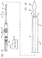
- FIGS. 1A and 1B illustrate a medical system 10 according to the present invention.
- the system 10 includes a catheter 12 having a handle 13 and a wire guide 20 disposed through a lumen 14 of the catheter 12.
- the catheter 12 includes an elongate sheath 15 having a proximal portion 16 and a distal portion 17.
- the lumen 14 includes one or more ports exiting the lumen 14. As shown in FIG. 1B , the lumen 14 has a port 19 opening at a distal end 21 of the catheter 12.
- FIGS. 2 and 3 illustrate embodiments of the wire guide 20.
- the wire guide 20 provides both navigation through body passageways and cannulation once the wire guide 20 is properly positioned within the passageway. A separate cutting wire for cannulation is not necessary.
- the wire guide 20 includes an elongate shaft 22 having a non-cutting proximal portion 24 and a distal portion 26 for navigation through body passageways.
- the wire guide 20 also includes a cutting portion 28.
- a connector 23 may be removably connected to the proximal portion 24 of the wire guide 20 (see FIG. 1A ).
- the connector 23 connects a power supply 27 to the wire guide 20 (described below).
- the distal portion 26 of the wire guide 20 includes a non-cutting tip 30 having an atraumatic profile.
- the tip 30 may be tapered, curvilinear, rounded and the like. This configuration provides for smooth entry into body passageways having strictures or blockages or tortuous configurations.
- the atraumatic tip profile also helps to prevent the distal tip 30 from inadvertently snagging and thereby unnecessarily traumatizing surrounding body tissues.
- the wire guide 20 may also include a contrast dye injection port 33 as shown in FIG. 1A .
- the injection port 33 may be connected to a separate lumen or connected to the wire guide lumen 14.
- the wire guide 20, except for the features as described herein and shown in the figures, may be any type of wire guide known to one of skill in the art.
- the non-cutting portion of wire guide 20 may be a helical wire, a simple wire, a braided wire, and the like.
- the cutting portion 28 of the wire guide 20 may be a simple wire having a smooth profile.
- the cutting portion 28 of the wire guide 20 may have a patterned profile to maximize the current delivery to portions of the tissue.
- the cutting portion 28 of the wire guide 20 may include a region 38 of highly electroconductive material extending longitudinally along the cutting portion 28, as shown in FIG. 5A .
- the region 38 may be used to concentrate the current delivery to a specific site at the stricture rather than having current radiating in all directions from the cutting portion 28.
- the cutting portion 28 of the wire guide 20 may be a region 31 extending longitudinally along the shaft 22 of the wire guide 20 where only the region 31 may be used for cannulation.
- the region 31 may extend longitudinally along a portion of the shaft 22 but not around the entire circumference of the shaft 22 (see FIG. 5B and 5C ).
- the cutting portion 28 of the wire guide 20 may be directionally targeted to the tissue to be cannulated.
- the proximal portion 24 and/or the cutting portion 28 of the elongate shaft 22 may be relatively stiff or have a higher durometer to provide greater control.
- the wire guide 20 is disposed in the lumen 14 of the catheter 12.
- the wire guide 20 may be provided for use in a long wire or short wire exchange procedure.
- the distal portion 26 of the wire guide 20 is disposed in the lumen 14 and the proximal portion of the wire guide 20 is positioned external to the catheter 12.
- the wire guide 20 may be remotely disconnected from the catheter 12 at the work site, such as within a lumen or other bodily passage/cavity, and additional devices may be placed over the wire guide 20.
- a short wire exchange system is described in U.S. Publication No. 2005/0070794 .
- the wire guide 20 may also be disposed in the lumen 14 of the catheter 12 in a conventional long wire exchange as will be understood by one skilled in the art. Any type of catheter configured for use with a wire guide may be used with the wire guide of the present invention.
- the distal portion 26 of the wire guide 20 extends distally from the port 19 at the distal end 21 of the catheter 12.
- the wire guide 20 may be extended distally so that the cutting portion 28 is disposed distal of the port 19 and can be used to cannulate tissue as described below.
- the tip 30 may be tapered and extend distally beyond the cutting portion 28 between about 2.5 to 25 centimeters (cm), preferably about 5 to 10 cm.
- the cutting portion 28 may be about 0.5 to 5 cm in length.
- the cutting portion 28 of the wire guide 20 extents externally from the lumen 14 of the catheter 12 through side ports 19a and 19b so that the cutting portion 28 extends generally axially with respect to the catheter 12. At least a portion of the distal portion 26 of the wire guide 20 may also extend distally from the port 19 of the catheter 12.
- the port 19b may be located about 5-20 cm proximal from the distal end 21 of the catheter 12.
- the spacing between the ports 19a and 19b may be the same length as the cutting portion 28, or may be longer or shorter than the cutting portion 28.
- the cutting portion 28 may be about 0.5 to 5 cm in length.
- the port 19a may be spaced apart from the port 19b about 0.5 to about 3 cm.
- the wire guide 20 is configured to be movably disposed in the catheter 12.
- the wire guide 20 may be extended distally so that the cutting portion 28 is exposed external to the catheter 12 and the distal portion 26 extends distally through the port 19.
- the wire guide 20 may be retracted proximally so that the distal portion 26 of the wire guide 20 may be retracted into the catheter 12 so that the wire guide 20 is also removed proximally through the ports 19b and 19a.
- the wire guide 20 may be moved distally through the lumen 14 and extended through the port 19, bypassing the ports 19a and 19b upon re-extension to be used as a wire guide or for cannulating an additional stricture.
- the cutting portion 28 of the wire guide 20 may be extended through the port 19 and be energized.
- the cutting portion 28 of the wire guide 20 may be movably disposed in the catheter 12 and configured to extend externally from the lumen 14 of the catheter 12 through a channel 19c so that the cutting portion 28 extends generally axially with respect to the catheter 12 as shown in FIGS. 5A and 5B . Similar to the embodiments described above, the cutting portion 28 of the wire guide 20 extends external to the catheter 12 so that a stricture may be cannulated. In some embodiments having a channel 19c, the cutting portion 28 may be bowed to extend beyond the catheter 12. The cutting portion 28 may be bowed by using ramp-like structures 43 on either side of the channel 19c to angle the cutting portion 28 of the wire guide 20 as the cutting portion exits and reenters the lumen 14.
- the distal portion 26 may extend distally through the port 19 similar to the embodiments described above.
- the channel 19c may be located about 5-20 cm proximal from the distal end 21 of the catheter 12.
- the length of the cutting portion 28 exposed in the channel 19 may be about 0.5 to about 5 cm.
- the wire guide 20 may be retracted proximally through the channel 19c so that the tip 30 of the wire guide 20 is completely withdrawn into the lumen 14.
- the wire guide 20 may be re-extended through the channel 19c and in the embodiments having the ramp-like structure 43, the wire guide 20 may be redirected at an angle along the structure 43 and away from the distal end 21 of the catheter 12.
- the wire guide 20 may have conventional dimensions and be made from conventional materials where at least some of the components are capable of conducting current.
- the length of the wire guide 20 may range from about 40 to 480 cm.
- An outside diameter of the wire guide 20 may range from about 0.020 to 0.13 cm (0.008 to 0.05 inches).
- suitable materials for forming the portions of the wire guide 20 that are electroconductive include, but are not limited to stainless steel, tantalum, nitinol; gold, silver, tungsten, platinum, inconel, cobalt-chromium alloys and iridium, all of which are commercially available metals or alloys used in the fabrication of medical devices.
- Other portions of the wire guide may be formed from a medically-acceptable polymer.
- exemplary polymers include, but are not limed to, cellulose acetate, cellulose nitrate, silicone, polyethylene, high density polyethylene, polyethylene teraphthalate, polyurethane, polytetrafluoroethylene, polyamide, polyester, polyorthoester, polyvinyl chloride (PVC), polypropylene, acrylonitrile-butadienestyrene (ABS), polycarbonate, polyurethane, nylon silicone, and polyanhydride.
- PVC polyvinyl chloride
- ABS acrylonitrile-butadienestyrene
- the wire guide 20 may be manufactured using conventional techniques.
- the wire guide 20 or portions thereof may also be coated to provide for smoother entry into a stricture and to provide an insulating layer 36 on the wire guide 20.
- the insulating layer 36 may cover the entire wire guide 20 with the exception of the cutting portion 28, which remains bare to convey current to the tissue (described below).
- the insulating layer 36 may be made from any insulating material suitable to protect against electrical hazards and may be selected based on the degree of insulation required and according to Standards IEC 60601-2-2, IEC 601-2-18 and AAMI HF 18.
- the insulating layer may comprise a polymer, for example, polytetrafluoroethlyene, polyimide, fluoropolymer, or PEBAX.
- a plurality of insulating layers 36 may also be included.
- the plurality of layers 36 may be made from the same or different materials.
- the plurality of layers 36 may cover a portion of the wire guide 20 and the thickness and number of layers at different portions of the wire guide 20 may vary.
- the tip 30 may include more insulating layers 36 than the proximal portion 24 of the wire guide 20 in embodiments where the proximal portion 24 is generally disposed within catheter 12 and is insulated thereby.
- the cutting portion 28 may extend only along the region 31 and the remaining circumferential area of the shaft 22 may include at least one layer 36.
- Radiopaque materials may be added to the layer 36. Also, radiopaque materials may be placed directly on or within portions of the wire guide 20 and the catheter 12. For example, radiopaque materials may be placed near both ends of the cutting portion 28 and/or along the cutting portion 28 so that the position of the cutting portion 28 may be viewable by the wire guide operator using fluoroscopy. In the embodiment shown in FIG. 2 , one or more bands 70 are present on the wire guide 20 and the catheter 12. Radiopaque markers having different sizes and/or different shapes may be used to identify different portions of the wire guide 20 and for positioning the cutting portion 28, as will be understood by one skilled in the art.
- radiopaque materials and markers are known in the art, and any suitable material and/or marker can be utilized in the present invention.
- Common radiopaque materials include barium sulfate, bismuth subcarbonate, and zirconium dioxide.
- Other radiopaque elements include: cadmium, tungsten, gold, tantalum, bismuth, platinum, iridium, and rhodium.
- iodine may be employed for its radiopacity and antimicrobial properties. Radiopacity is typically determined by fluoroscope or x-ray film.
- Radiopaque, physiologically compatible materials include metals and alloys selected from the Platinum Group metals, especially platinum, rhodium, palladium, rhenium, as well as tungsten, gold, silver, tantalum, and alloys of these metals. These metals have significant radiopacity and in their alloys may be tailored to accomplish an appropriate blend of flexibility and stiffness. They are also largely biocompatible. For example, a platinum/tungsten alloy, e.g., 8% tungsten and the remainder platinum may be used.
- the proximal portion 24 of the wire guide 20 may be removably connected to the power source 27 for providing current to the cutting portion 28 for cannulating the stricture.
- the wire guide 20 may be used as a conventional wire guide when no current is supplied to the wire guide and the wire guide 20 may be used for cannulation when current is supplied.
- the cutting portion 28 may be activated and deactivated by the power source 27 itself or by removably connecting the power source 27 through the connector 23 via a lead 42.
- the power source 27 may be any power source known to one of skill in the art.
- the power supply 27 may be a conventional power supply having conventional control circuitry to provide a constant or modulated AC or DC signal.
- the power may also be supplied as an RF signal.
- the signal is transmitted by the lead 42 to the connector 23 and to the wire guide 20.
- the connector 23 may be removable to permit devices, such as catheters, to be advanced over the proximal end of the wire guide 20.
- the connector 23 may also be rotatable to allow the wire guide 20 to be rotated and steered during navigation to the body location.
- the wire guide 20 may be positioned for cutting prior to connection to the power source 27. Exemplary power sources and connectors for use with a wire guide are described in U.S. Patent No. 6,602,250 , which is incorporated by reference herein in its entirety.
- FIG. 5 An exemplary procedure utilizing the wire guide 20, for example in accessing the biliary system via the Sphincter of Oddi is shown in FIG. 5 and is described as follows.
- An endoscope 59 is advanced into the patient and positioned near the Sphincter of Oddi 61 in the Papilla of Vater 63.
- the endoscope 59 is positioned to allow viewing of sphincter 61 as is known.
- the catheter 12 and the wire guide 20 are extended out of opening 65 in endoscope 59.
- the wire guide 20 is extended into engagement with sphincter 61 by inserting the tip 30 of the wire guide 20 into the Ampulla of Vater, which communicates with the common bile duct 67 and the pancreatic duct 69.
- the tip 30 may be extended into the Ampulla of Vater until the cutting portion 28 is aligned with the stricture to be cannulated.
- stricture refers to any narrowing of a lumen in relation to an adjacent lumen portion.
- the stricture may be a sphincter opening where the diameter of the sphincter opening is smaller than the adjacent lumen or the stricture may be an abnormal narrowing of a lumen due to a tumor and the like.
- the cutting portion 28 of the wire guide 20 may be oriented using the markers 70 to position the cutting portion 28, for example, in the center of sphincter 61 so that the cutting plane is oriented transversely with respect to the central Ampulla of Vater.
- the open portion of the channel having the cutting portion 28 exposed to the tissue may be aligned so that the cutting portion 28 within the channel 19c is positioned at the tissue for subsequent cannulation.
- the desired orientation will depend on the stricture and the individual anatomy of each patient.
- the power source 27 may be connected to the connector 23 and/or turned on to supply power so that the tissue may be cannulated with the cutting portion 28. Any tissue not in contact with the cutting portion 28 of the wire guide 20 will be protected by the insulating layer 36, the catheter 12 or both.
- the power source 27 may be turned off and in some embodiments, the connector 23 may be disconnected from the proximal portion 24 of the wire guide 20. Additional medical procedures may be conducted using the wire guide 20 in the non-energized state as a traditional wire guide.
Description
- The present invention relates to medical devices, and more particularly to medical devices, such as sphincterotomes and wire guides, used in surgical procedures.
- Medical devices, such as catheters delivered over wire guides, are used in the pancreatobiliary system for endoscopic or other minimally invasive surgery.
- Such devices are described for example in documents
US 20030032936 orWO 9922658 - Typically, an Endoscopic Retrograde Cholangiopancreatography (ERCP) procedure is performed when the Sphincter of Oddi becomes constricted due to disease or trauma by introducing a catheter device from a duodenoscope through the ampullary orifice (Papilla of Vater) and into the biliary tree, which includes the bile duct, pancreatic duct and hepatic ducts of the liver. In the ERCP procedure, a wire guide is first introduced into the biliary tree and the cannulation device, which is usually a sphincterotome/papllitome or ECRP catheter, is introduced over the wire guide and into the biliary tree to perform a first operation, which could be diagnostic in nature, such as injecting contrast media, or for therapeutic purposes, such as enlarging the ampullary orifice. Introducing the wire guide prior to or at the same time as the sphincterotome allows for cannulation of closed sphincters and other strictures due to the smaller diameter of the wire guide as compared to the sphincterotome.
- The sphincterotome may be used both to cannulate the ductal system and to enlarge the opening by delivery of electrical current to a bowed cutting wire at the distal end of the sphincterotome. Exemplary sphincterotomes typically include at least two lumens extending through the shaft thereof. One lumen is provided for an operating wire that is connected to the cutting wire and the other lumen is provided for the wire guide. Accordingly, typical sphincterotomes have a relatively large cross-section - much larger than a typical wire guide. The wire guide is usually left in place while the sphincterotome is advanced, operated and then removed. The wire guide can be used to provide subsequent access for other devices when additional medical procedures are performed, such as to remove a stone, to open a stricture, or to sample tissue.
- Complications are associated with the ERCP procedure and accessing the papilla of the pancreatic duct with the known medical devices described above, particularly multi-lumen sphincterotomes having a relatively large cross-section. Complications include acute pancreatitis, bleeding, duodenal perforation, cholangitis, etc. generally due to mechanical and thermal trauma of the papilla. Although complication rates are generally low, decreasing trauma to the papilla will help further lower the complication rates. The present invention provides a wire guide adapted to cannulate a stricture without requiring a separate device, such as a sphincterotome having a cutting wire, to perform the procedure. The present invention also provides a single lumen catheter suitable for use with the wire guide of the present invention.
- The scope of the present invention is set forth in the appended claims. A medical system configured for cannulation of a lumen having a stricture is provided. The medical system includes an elongate sheath having a proximal portion, a distal portion and a first lumen at least partially extending through the sheath. The medical system also includes a wire guide having a cutting portion, a non-cutting tip portion and a non-cutting shaft portion proximal to the cutting portion. The wire guide extends at least partially through the first lumen and at least a portion of the cutting portion is positionable outside the sheath to cannulate the stricture.
- Embodiments of the present invention will now be described by way of example with reference to the accompanying drawings, in which:
- FIG. IA is a side view of a catheter handle for a wire guide;
- FIG. IB is an enlarged side view of a distal portion of a distal end of a catheter with a wire guide extending through a lumen thereof;
-
FIG. 2 is a partial side view of the wire guide shown inFIG. 1B ; -
FIG. 3 is a partial side view of an alternative embodiment of the wire guide and catheter; -
FIG. 4A is a partial side view of an alternative embodiment of the wire guide and catheter; -
FIG. 4B is a partial side view of an alternative embodiment of the wire guide and catheter; -
FIG. 5A is a partial side view of the cutting portion of the wire guide; -
FIG. 5B is a partial side view of an alternative embodiment of the cutting portion of the wire guide; -
FIG. 5C is a cross- sectional view of the cutting portion of the wire guide shown inFIG. 5B through A-A; -
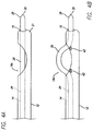
FIG. 6A is a partial view of the wire guide shown inFIG. 2 being used to cannulate a stricture in the biliary system; and -
FIG. 6B is a partial view of the wire guide shown inFIG. 4A being used to cannulate a stricture in the biliary system. - The invention is described with reference to the drawings in which like elements are referred to by like numerals. The relationship and functioning of the various elements of this invention are better understood by the following detailed description. However, the embodiments of this invention as described below are by way of example only, and the invention is not limited to the embodiments illustrated in the drawings. It should also be understood that the drawings are not to scale and in certain instances details have been omitted, which are not necessary for an understanding of the present invention, such as conventional details of fabrication and assembly.
-
FIGS. 1A and 1B illustrate amedical system 10 according to the present invention. Thesystem 10 includes acatheter 12 having ahandle 13 and awire guide 20 disposed through alumen 14 of thecatheter 12. Thecatheter 12 includes anelongate sheath 15 having aproximal portion 16 and adistal portion 17. Thelumen 14 includes one or more ports exiting thelumen 14. As shown inFIG. 1B , thelumen 14 has aport 19 opening at adistal end 21 of thecatheter 12. -
FIGS. 2 and 3 illustrate embodiments of thewire guide 20. Thewire guide 20 provides both navigation through body passageways and cannulation once thewire guide 20 is properly positioned within the passageway. A separate cutting wire for cannulation is not necessary. Thewire guide 20 includes anelongate shaft 22 having a non-cuttingproximal portion 24 and adistal portion 26 for navigation through body passageways. Thewire guide 20 also includes a cuttingportion 28. Aconnector 23 may be removably connected to theproximal portion 24 of the wire guide 20 (seeFIG. 1A ). Theconnector 23 connects apower supply 27 to the wire guide 20 (described below). Thedistal portion 26 of thewire guide 20 includes anon-cutting tip 30 having an atraumatic profile. For example, thetip 30 may be tapered, curvilinear, rounded and the like. This configuration provides for smooth entry into body passageways having strictures or blockages or tortuous configurations. The atraumatic tip profile also helps to prevent thedistal tip 30 from inadvertently snagging and thereby unnecessarily traumatizing surrounding body tissues. Thewire guide 20 may also include a contrastdye injection port 33 as shown inFIG. 1A . Theinjection port 33 may be connected to a separate lumen or connected to thewire guide lumen 14. - The
wire guide 20, except for the features as described herein and shown in the figures, may be any type of wire guide known to one of skill in the art. By way of non-limiting example, the non-cutting portion ofwire guide 20 may be a helical wire, a simple wire, a braided wire, and the like. In some embodiments, the cuttingportion 28 of thewire guide 20 may be a simple wire having a smooth profile. Alternatively, the cuttingportion 28 of thewire guide 20 may have a patterned profile to maximize the current delivery to portions of the tissue. The cuttingportion 28 of thewire guide 20 may include aregion 38 of highly electroconductive material extending longitudinally along the cuttingportion 28, as shown inFIG. 5A . Theregion 38 may be used to concentrate the current delivery to a specific site at the stricture rather than having current radiating in all directions from the cuttingportion 28. Alternatively, the cuttingportion 28 of thewire guide 20 may be aregion 31 extending longitudinally along theshaft 22 of thewire guide 20 where only theregion 31 may be used for cannulation. For example, theregion 31 may extend longitudinally along a portion of theshaft 22 but not around the entire circumference of the shaft 22 (seeFIG. 5B and 5C ). In this embodiment, the cuttingportion 28 of thewire guide 20 may be directionally targeted to the tissue to be cannulated. In some embodiments, theproximal portion 24 and/or the cuttingportion 28 of theelongate shaft 22 may be relatively stiff or have a higher durometer to provide greater control. - At least a portion of the
wire guide 20 is disposed in thelumen 14 of thecatheter 12. Thewire guide 20 may be provided for use in a long wire or short wire exchange procedure. In the short wire exchange system, thedistal portion 26 of thewire guide 20 is disposed in thelumen 14 and the proximal portion of thewire guide 20 is positioned external to thecatheter 12. In the short wire exchange system, thewire guide 20 may be remotely disconnected from thecatheter 12 at the work site, such as within a lumen or other bodily passage/cavity, and additional devices may be placed over thewire guide 20. A short wire exchange system is described inU.S. Publication No. 2005/0070794 . Thewire guide 20 may also be disposed in thelumen 14 of thecatheter 12 in a conventional long wire exchange as will be understood by one skilled in the art. Any type of catheter configured for use with a wire guide may be used with the wire guide of the present invention. - As shown in
FIG. 2 , thedistal portion 26 of thewire guide 20 extends distally from theport 19 at thedistal end 21 of thecatheter 12. Thewire guide 20 may be extended distally so that the cuttingportion 28 is disposed distal of theport 19 and can be used to cannulate tissue as described below. In some embodiments, thetip 30 may be tapered and extend distally beyond the cuttingportion 28 between about 2.5 to 25 centimeters (cm), preferably about 5 to 10 cm. The cuttingportion 28 may be about 0.5 to 5 cm in length. - As shown in
FIG. 3 , the cuttingportion 28 of thewire guide 20 extents externally from thelumen 14 of thecatheter 12 throughside ports portion 28 extends generally axially with respect to thecatheter 12. At least a portion of thedistal portion 26 of thewire guide 20 may also extend distally from theport 19 of thecatheter 12. Theport 19b may be located about 5-20 cm proximal from thedistal end 21 of thecatheter 12. The spacing between theports portion 28, or may be longer or shorter than the cuttingportion 28. For example, the cuttingportion 28 may be about 0.5 to 5 cm in length. In some embodiments, theport 19a may be spaced apart from theport 19b about 0.5 to about 3 cm. The lengths provided above are meant to be non-limiting examples and one skilled in the art will understand that other lengths for the cuttingportion 28, thetip 30 and the distance between the ports are possible. Thewire guide 20 is configured to be movably disposed in thecatheter 12. Thewire guide 20 may be extended distally so that the cuttingportion 28 is exposed external to thecatheter 12 and thedistal portion 26 extends distally through theport 19. After cannulating the sphincter, thewire guide 20 may be retracted proximally so that thedistal portion 26 of thewire guide 20 may be retracted into thecatheter 12 so that thewire guide 20 is also removed proximally through theports wire guide 20 may be moved distally through thelumen 14 and extended through theport 19, bypassing theports portion 28 of thewire guide 20 may be extended through theport 19 and be energized. - In some embodiments, the cutting
portion 28 of thewire guide 20 may be movably disposed in thecatheter 12 and configured to extend externally from thelumen 14 of thecatheter 12 through achannel 19c so that the cuttingportion 28 extends generally axially with respect to thecatheter 12 as shown inFIGS. 5A and 5B . Similar to the embodiments described above, the cuttingportion 28 of thewire guide 20 extends external to thecatheter 12 so that a stricture may be cannulated. In some embodiments having achannel 19c, the cuttingportion 28 may be bowed to extend beyond thecatheter 12. The cuttingportion 28 may be bowed by using ramp-like structures 43 on either side of thechannel 19c to angle the cuttingportion 28 of thewire guide 20 as the cutting portion exits and reenters thelumen 14. Thedistal portion 26 may extend distally through theport 19 similar to the embodiments described above. Thechannel 19c may be located about 5-20 cm proximal from thedistal end 21 of thecatheter 12. The length of the cuttingportion 28 exposed in thechannel 19 may be about 0.5 to about 5 cm. Similar to the embodiment having a pair ofports FIG. 3 , thewire guide 20 may be retracted proximally through thechannel 19c so that thetip 30 of thewire guide 20 is completely withdrawn into thelumen 14. Thewire guide 20 may be re-extended through thechannel 19c and in the embodiments having the ramp-like structure 43, thewire guide 20 may be redirected at an angle along thestructure 43 and away from thedistal end 21 of thecatheter 12. - The
wire guide 20 may have conventional dimensions and be made from conventional materials where at least some of the components are capable of conducting current. For example, the length of thewire guide 20 may range from about 40 to 480 cm. An outside diameter of thewire guide 20 may range from about 0.020 to 0.13 cm (0.008 to 0.05 inches). - Examples of suitable materials for forming the portions of the
wire guide 20 that are electroconductive include, but are not limited to stainless steel, tantalum, nitinol; gold, silver, tungsten, platinum, inconel, cobalt-chromium alloys and iridium, all of which are commercially available metals or alloys used in the fabrication of medical devices. Other portions of the wire guide may be formed from a medically-acceptable polymer. For example, exemplary polymers include, but are not limed to, cellulose acetate, cellulose nitrate, silicone, polyethylene, high density polyethylene, polyethylene teraphthalate, polyurethane, polytetrafluoroethylene, polyamide, polyester, polyorthoester, polyvinyl chloride (PVC), polypropylene, acrylonitrile-butadienestyrene (ABS), polycarbonate, polyurethane, nylon silicone, and polyanhydride. Thewire guide 20 may be manufactured using conventional techniques. Examples of wire guides having features that may be included in the present invention include the FUSION® System, DASH® Direct Access System, OMNI devices, MINI-TOME PC® and the like (available from Cook Endoscopy, Winston-Salem, N.C.) - The
wire guide 20 or portions thereof may also be coated to provide for smoother entry into a stricture and to provide an insulatinglayer 36 on thewire guide 20. In some embodiments, the insulatinglayer 36 may cover theentire wire guide 20 with the exception of the cuttingportion 28, which remains bare to convey current to the tissue (described below). The insulatinglayer 36 may be made from any insulating material suitable to protect against electrical hazards and may be selected based on the degree of insulation required and according to Standards IEC 60601-2-2, IEC 601-2-18 and AAMI HF 18. In some embodiments the insulating layer may comprise a polymer, for example, polytetrafluoroethlyene, polyimide, fluoropolymer, or PEBAX. A plurality of insulatinglayers 36 may also be included. The plurality oflayers 36 may be made from the same or different materials. The plurality oflayers 36 may cover a portion of thewire guide 20 and the thickness and number of layers at different portions of thewire guide 20 may vary. For example, thetip 30 may include moreinsulating layers 36 than theproximal portion 24 of thewire guide 20 in embodiments where theproximal portion 24 is generally disposed withincatheter 12 and is insulated thereby. In some embodiments, the cuttingportion 28 may extend only along theregion 31 and the remaining circumferential area of theshaft 22 may include at least onelayer 36. - Radiopaque materials may be added to the
layer 36. Also, radiopaque materials may be placed directly on or within portions of thewire guide 20 and thecatheter 12. For example, radiopaque materials may be placed near both ends of the cuttingportion 28 and/or along the cuttingportion 28 so that the position of the cuttingportion 28 may be viewable by the wire guide operator using fluoroscopy. In the embodiment shown inFIG. 2 , one ormore bands 70 are present on thewire guide 20 and thecatheter 12. Radiopaque markers having different sizes and/or different shapes may be used to identify different portions of thewire guide 20 and for positioning the cuttingportion 28, as will be understood by one skilled in the art. - Several examples of suitable radiopaque materials and markers are known in the art, and any suitable material and/or marker can be utilized in the present invention. Common radiopaque materials include barium sulfate, bismuth subcarbonate, and zirconium dioxide. Other radiopaque elements include: cadmium, tungsten, gold, tantalum, bismuth, platinum, iridium, and rhodium. In one embodiment, iodine may be employed for its radiopacity and antimicrobial properties. Radiopacity is typically determined by fluoroscope or x-ray film. Radiopaque, physiologically compatible materials include metals and alloys selected from the Platinum Group metals, especially platinum, rhodium, palladium, rhenium, as well as tungsten, gold, silver, tantalum, and alloys of these metals. These metals have significant radiopacity and in their alloys may be tailored to accomplish an appropriate blend of flexibility and stiffness. They are also largely biocompatible. For example, a platinum/tungsten alloy, e.g., 8% tungsten and the remainder platinum may be used.
- As shown in
FIG. 1A , theproximal portion 24 of thewire guide 20 may be removably connected to thepower source 27 for providing current to the cuttingportion 28 for cannulating the stricture. Thewire guide 20 may be used as a conventional wire guide when no current is supplied to the wire guide and thewire guide 20 may be used for cannulation when current is supplied. The cuttingportion 28 may be activated and deactivated by thepower source 27 itself or by removably connecting thepower source 27 through theconnector 23 via alead 42. Thepower source 27 may be any power source known to one of skill in the art. For example, thepower supply 27 may be a conventional power supply having conventional control circuitry to provide a constant or modulated AC or DC signal. The power may also be supplied as an RF signal. The signal is transmitted by thelead 42 to theconnector 23 and to thewire guide 20. Theconnector 23 may be removable to permit devices, such as catheters, to be advanced over the proximal end of thewire guide 20. Theconnector 23 may also be rotatable to allow thewire guide 20 to be rotated and steered during navigation to the body location. Alternatively, thewire guide 20 may be positioned for cutting prior to connection to thepower source 27. Exemplary power sources and connectors for use with a wire guide are described inU.S. Patent No. 6,602,250 , which is incorporated by reference herein in its entirety. - An exemplary procedure utilizing the
wire guide 20, for example in accessing the biliary system via the Sphincter of Oddi is shown inFIG. 5 and is described as follows. Anendoscope 59 is advanced into the patient and positioned near the Sphincter ofOddi 61 in the Papilla ofVater 63. Theendoscope 59 is positioned to allow viewing ofsphincter 61 as is known. Next, thecatheter 12 and thewire guide 20 are extended out of opening 65 inendoscope 59. Thewire guide 20 is extended into engagement withsphincter 61 by inserting thetip 30 of thewire guide 20 into the Ampulla of Vater, which communicates with thecommon bile duct 67 and thepancreatic duct 69. Thetip 30 may be extended into the Ampulla of Vater until the cuttingportion 28 is aligned with the stricture to be cannulated. As used herein, the term stricture refers to any narrowing of a lumen in relation to an adjacent lumen portion. For example, the stricture may be a sphincter opening where the diameter of the sphincter opening is smaller than the adjacent lumen or the stricture may be an abnormal narrowing of a lumen due to a tumor and the like. The cuttingportion 28 of thewire guide 20 may be oriented using themarkers 70 to position the cuttingportion 28, for example, in the center ofsphincter 61 so that the cutting plane is oriented transversely with respect to the central Ampulla of Vater. Similarly, in embodiments having the cuttingportion 28 of thewire guide 20 disposed in thechannel 19c, the open portion of the channel having the cuttingportion 28 exposed to the tissue may be aligned so that the cuttingportion 28 within thechannel 19c is positioned at the tissue for subsequent cannulation. The desired orientation will depend on the stricture and the individual anatomy of each patient. Once the cuttingportion 28 is properly oriented, thepower source 27 may be connected to theconnector 23 and/or turned on to supply power so that the tissue may be cannulated with the cuttingportion 28. Any tissue not in contact with the cuttingportion 28 of thewire guide 20 will be protected by the insulatinglayer 36, thecatheter 12 or both. After cannulating the stricture, thepower source 27 may be turned off and in some embodiments, theconnector 23 may be disconnected from theproximal portion 24 of thewire guide 20. Additional medical procedures may be conducted using thewire guide 20 in the non-energized state as a traditional wire guide. - Unless otherwise indicated, all ordinary words and terms used herein shall take their customary meaning as defined in The New Shorter Oxford English Dictionary, 1993 editi on. All technical terms shall take on their customary meaning as established by the appropriate technical discipline utilized by those normally skilled in that particular art area. All medical terms shall take their meaning as defined by Stedman's Medical Dictionary, 27th editi on.
- It is therefore intended that the foregoing detailed description be regarded as illustrative rather than limiting, and that it be understood that it is the following claims, including all equivalents, that are intended to define the scope of this invention.
Claims (11)
- A medical system configured for cannulation of a body passageway having a stricture, the system comprising:an elongate sheath (15) comprising a proximal portion (16), a distal portion (17) and a lumen (14) at least partially extending through the sheath and connected to a port (19) in the distal portion of the elongate sheath; anda wire guide (20) movable relative to the elongate sheath and distally extendable through the port, the wire guide extending at least partially through the lumen (14);characterised by the wire guide comprising a cutting portion (28) and a non-cutting tip portion (30) distal to the cutting portion, the tip portion comprising an atraumatic profile and a non-cutting shaft portion (24) proximal to the cutting portion;wherein the tip portion is distally extendable from a distal end of the sheath through the port (19) and configured to navigate the body passageway; andwherein at least a portion of the cutting portion is extendable through a side port (19a, b, c) in the sheath and is positionable outside the sheath to cannulate the stricture.
- The medical system of claim 1, wherein the cutting portion comprises an electroconductive material.
- The medical system of claim 2, wherein the wire guide is operatively connected to a power source (27) for energizing the cutting portion applicable as a cutting element
- The medical system of claim 2, wherein non-cutting shaft and tip portions of the wire guide each comprise an insulating layer.
- The medical system of claim 4, wherein the insulating layer comprises polytetrafluoroethylene.
- The medical system of claim 1, wherein the cutting portion includes an electroconductive region extending generally axially with respect to the sheath.
- The medical system of claim 1, wherein the cutting portion is distally extendable through the port (19).
- The medical system of claim 1, wherein the side port comprises a pair of side ports exiting the sheath.
- The medical system of claim 1, wherein the side port comprises an elongated side port forming a channel in the sheath.
- The medical system of claim 1, wherein the wire guide includes a tapered tip portion.
- The medical system of claim 1, wherein the cutting portion is about 5 to 30 millimeters in length.
Applications Claiming Priority (2)
| Application Number | Priority Date | Filing Date | Title |
|---|---|---|---|
| US81443406P | 2006-06-16 | 2006-06-16 | |
| PCT/US2007/013746 WO2007149263A1 (en) | 2006-06-16 | 2007-06-12 | Wire guide sphincterotome |
Publications (2)
| Publication Number | Publication Date |
|---|---|
| EP2029040A1 EP2029040A1 (en) | 2009-03-04 |
| EP2029040B1 true EP2029040B1 (en) | 2016-01-27 |
Family
ID=38596245
Family Applications (1)
| Application Number | Title | Priority Date | Filing Date |
|---|---|---|---|
| EP07795999.7A Not-in-force EP2029040B1 (en) | 2006-06-16 | 2007-06-12 | Wire guide sphincterotome |
Country Status (6)
| Country | Link |
|---|---|
| US (1) | US20070293857A1 (en) |
| EP (1) | EP2029040B1 (en) |
| JP (1) | JP2009539552A (en) |
| AU (1) | AU2007261646A1 (en) |
| CA (1) | CA2661594A1 (en) |
| WO (1) | WO2007149263A1 (en) |
Families Citing this family (5)
| Publication number | Priority date | Publication date | Assignee | Title |
|---|---|---|---|---|
| US20090048486A1 (en) * | 2007-08-08 | 2009-02-19 | Wilson-Cook Medical Inc. | Distal Tip for an Endoscope |
| US8771298B2 (en) | 2009-05-13 | 2014-07-08 | The Regents Of The University Of California | Treatment of sphincter dysfunction |
| WO2014158513A1 (en) | 2013-03-13 | 2014-10-02 | Cook Medical Technologies Llc | Rotation mechanism for bipolar and monopolar devices |
| JP6728046B2 (en) * | 2013-12-12 | 2020-07-22 | ヌバイラ, インコーポレイテッド | Catheter and handle assembly, system, and method |
| US11337753B2 (en) | 2020-07-03 | 2022-05-24 | Telltale Llc | Tissue cutting systems and methods |
Family Cites Families (14)
| Publication number | Priority date | Publication date | Assignee | Title |
|---|---|---|---|---|
| US4493320A (en) * | 1982-04-02 | 1985-01-15 | Treat Michael R | Bipolar electrocautery surgical snare |
| US5810807A (en) * | 1996-05-22 | 1998-09-22 | Ganz; Robert A. | Sphincterotome with deflectable cutting plane and method of using the same |
| AU5905098A (en) * | 1996-12-23 | 1998-07-17 | Advanced Coronary Intervention | Radio frequency transmyocardial revascularization |
| US6056743A (en) * | 1997-11-04 | 2000-05-02 | Scimed Life Systems, Inc. | Percutaneous myocardial revascularization device and method |
| JP2000237202A (en) * | 1999-02-25 | 2000-09-05 | Olympus Optical Co Ltd | Treating utensil for endoscope |
| US6514248B1 (en) * | 1999-10-15 | 2003-02-04 | Neothermia Corporation | Accurate cutting about and into tissue volumes with electrosurgically deployed electrodes |
| US6602250B2 (en) | 2000-01-31 | 2003-08-05 | Wilson-Cook Medical Incorporated | Echogenic wire knife |
| WO2001087399A2 (en) * | 2000-05-18 | 2001-11-22 | Wilson-Cook Medical Inc. | Medical device with improved wire guide access |
| CA2417988A1 (en) * | 2000-08-14 | 2002-02-21 | Boston Scientific Limited | Steerable sphincterotome and methods for cannulation, papillotomy and sphincterotomy |
| US20020072739A1 (en) * | 2000-12-07 | 2002-06-13 | Roberta Lee | Methods and devices for radiofrequency electrosurgery |
| US20030208219A1 (en) * | 2001-05-18 | 2003-11-06 | Aznoian Harold M. | Steerable biliary catheter |
| US7018346B2 (en) * | 2001-12-18 | 2006-03-28 | Scimed Life Systems, Inc. | Guide wire with adjustable flexibility |
| US8206320B2 (en) * | 2003-07-31 | 2012-06-26 | Cook Medical Technologies Llc | System and method for introducing multiple medical devices |
| WO2006049970A2 (en) * | 2004-10-27 | 2006-05-11 | Yuval Carmel | Radio-frequency device for passivation of vascular plaque and method of using same |
-
2007
- 2007-06-12 CA CA002661594A patent/CA2661594A1/en not_active Abandoned
- 2007-06-12 US US11/761,728 patent/US20070293857A1/en not_active Abandoned
- 2007-06-12 AU AU2007261646A patent/AU2007261646A1/en not_active Abandoned
- 2007-06-12 JP JP2009515448A patent/JP2009539552A/en active Pending
- 2007-06-12 WO PCT/US2007/013746 patent/WO2007149263A1/en active Application Filing
- 2007-06-12 EP EP07795999.7A patent/EP2029040B1/en not_active Not-in-force
Also Published As
| Publication number | Publication date |
|---|---|
| US20070293857A1 (en) | 2007-12-20 |
| JP2009539552A (en) | 2009-11-19 |
| EP2029040A1 (en) | 2009-03-04 |
| CA2661594A1 (en) | 2007-12-27 |
| AU2007261646A1 (en) | 2007-12-27 |
| WO2007149263A1 (en) | 2007-12-27 |
Similar Documents
| Publication | Publication Date | Title |
|---|---|---|
| JP5513116B2 (en) | A medical catheter with a stress concentrating part in the access port and reduced breaking force | |
| US8591563B2 (en) | Catheter with splittable wall shaft and peel tool | |
| EP0952864B1 (en) | Single operator exchange biliary catheter | |
| US8292872B2 (en) | Distal wire stop having adjustable handle | |
| JP2010503476A5 (en) | ||
| JP2007098158A (en) | Method and apparatus for electrosurgically obtaining access to biliary tree | |
| EP2029040B1 (en) | Wire guide sphincterotome | |
| US20090105638A1 (en) | Single use deflectable stylet | |
| WO2013095986A1 (en) | Biliary system catheter | |
| US8029473B2 (en) | Injection tube for catheter devices | |
| JP2009539552A5 (en) | ||
| JP4744522B2 (en) | Catheter with shaft and stripper that can break walls | |
| US20200214764A1 (en) | Devices, systems and methods for accessing a body lumen | |
| US10792094B2 (en) | Continuous compound curved tip for cannulation | |
| US11937871B2 (en) | Devices, systems, and methods for accessing a body lumen | |
| Ahlawat et al. | Endoscopes, guidewires, and accessories | |
| CN116490114A (en) | System and method for treating stenosis along the biliary and/or pancreatic tract | |
| EP3886959B1 (en) | Endoscopic system for energy delivery | |
| US9017246B2 (en) | Biliary catheter systems including stabilizing members | |
| Chapter | Endoscopes, and Accessories Guidewires | |
| WO2023225187A2 (en) | Medical device with a steerable tip |
Legal Events
| Date | Code | Title | Description |
|---|---|---|---|
| PUAI | Public reference made under article 153(3) epc to a published international application that has entered the european phase |
Free format text: ORIGINAL CODE: 0009012 |
|
| 17P | Request for examination filed |
Effective date: 20081215 |
|
| AK | Designated contracting states |
Kind code of ref document: A1 Designated state(s): AT BE BG CH CY CZ DE DK EE ES FI FR GB GR HU IE IS IT LI LT LU LV MC MT NL PL PT RO SE SI SK TR |
|
| AX | Request for extension of the european patent |
Extension state: AL BA HR MK RS |
|
| 17Q | First examination report despatched |
Effective date: 20100208 |
|
| RAP1 | Party data changed (applicant data changed or rights of an application transferred) |
Owner name: COOK MEDICAL TECHNOLOGIES LLC |
|
| RAP1 | Party data changed (applicant data changed or rights of an application transferred) |
Owner name: COOK MEDICAL TECHNOLOGIES LLC |
|
| DAX | Request for extension of the european patent (deleted) | ||
| GRAP | Despatch of communication of intention to grant a patent |
Free format text: ORIGINAL CODE: EPIDOSNIGR1 |
|
| INTG | Intention to grant announced |
Effective date: 20150710 |
|
| GRAS | Grant fee paid |
Free format text: ORIGINAL CODE: EPIDOSNIGR3 |
|
| GRAA | (expected) grant |
Free format text: ORIGINAL CODE: 0009210 |
|
| INTG | Intention to grant announced |
Effective date: 20151130 |
|
| AK | Designated contracting states |
Kind code of ref document: B1 Designated state(s): AT BE BG CH CY CZ DE DK EE ES FI FR GB GR HU IE IS IT LI LT LU LV MC MT NL PL PT RO SE SI SK TR |
|
| REG | Reference to a national code |
Ref country code: GB Ref legal event code: FG4D |
|
| REG | Reference to a national code |
Ref country code: CH Ref legal event code: EP |
|
| REG | Reference to a national code |
Ref country code: AT Ref legal event code: REF Ref document number: 772306 Country of ref document: AT Kind code of ref document: T Effective date: 20160215 |
|
| REG | Reference to a national code |
Ref country code: IE Ref legal event code: FG4D |
|
| REG | Reference to a national code |
Ref country code: DE Ref legal event code: R096 Ref document number: 602007044679 Country of ref document: DE |
|
| REG | Reference to a national code |
Ref country code: LT Ref legal event code: MG4D |
|
| REG | Reference to a national code |
Ref country code: NL Ref legal event code: MP Effective date: 20160127 |
|
| REG | Reference to a national code |
Ref country code: AT Ref legal event code: MK05 Ref document number: 772306 Country of ref document: AT Kind code of ref document: T Effective date: 20160127 |
|
| PG25 | Lapsed in a contracting state [announced via postgrant information from national office to epo] |
Ref country code: NL Free format text: LAPSE BECAUSE OF FAILURE TO SUBMIT A TRANSLATION OF THE DESCRIPTION OR TO PAY THE FEE WITHIN THE PRESCRIBED TIME-LIMIT Effective date: 20160127 |
|
| PG25 | Lapsed in a contracting state [announced via postgrant information from national office to epo] |
Ref country code: GR Free format text: LAPSE BECAUSE OF FAILURE TO SUBMIT A TRANSLATION OF THE DESCRIPTION OR TO PAY THE FEE WITHIN THE PRESCRIBED TIME-LIMIT Effective date: 20160428 Ref country code: FI Free format text: LAPSE BECAUSE OF FAILURE TO SUBMIT A TRANSLATION OF THE DESCRIPTION OR TO PAY THE FEE WITHIN THE PRESCRIBED TIME-LIMIT Effective date: 20160127 Ref country code: ES Free format text: LAPSE BECAUSE OF FAILURE TO SUBMIT A TRANSLATION OF THE DESCRIPTION OR TO PAY THE FEE WITHIN THE PRESCRIBED TIME-LIMIT Effective date: 20160127 Ref country code: IT Free format text: LAPSE BECAUSE OF FAILURE TO SUBMIT A TRANSLATION OF THE DESCRIPTION OR TO PAY THE FEE WITHIN THE PRESCRIBED TIME-LIMIT Effective date: 20160127 |
|
| PG25 | Lapsed in a contracting state [announced via postgrant information from national office to epo] |
Ref country code: LT Free format text: LAPSE BECAUSE OF FAILURE TO SUBMIT A TRANSLATION OF THE DESCRIPTION OR TO PAY THE FEE WITHIN THE PRESCRIBED TIME-LIMIT Effective date: 20160127 Ref country code: SE Free format text: LAPSE BECAUSE OF FAILURE TO SUBMIT A TRANSLATION OF THE DESCRIPTION OR TO PAY THE FEE WITHIN THE PRESCRIBED TIME-LIMIT Effective date: 20160127 Ref country code: AT Free format text: LAPSE BECAUSE OF FAILURE TO SUBMIT A TRANSLATION OF THE DESCRIPTION OR TO PAY THE FEE WITHIN THE PRESCRIBED TIME-LIMIT Effective date: 20160127 Ref country code: PL Free format text: LAPSE BECAUSE OF FAILURE TO SUBMIT A TRANSLATION OF THE DESCRIPTION OR TO PAY THE FEE WITHIN THE PRESCRIBED TIME-LIMIT Effective date: 20160127 Ref country code: IS Free format text: LAPSE BECAUSE OF FAILURE TO SUBMIT A TRANSLATION OF THE DESCRIPTION OR TO PAY THE FEE WITHIN THE PRESCRIBED TIME-LIMIT Effective date: 20160527 Ref country code: PT Free format text: LAPSE BECAUSE OF FAILURE TO SUBMIT A TRANSLATION OF THE DESCRIPTION OR TO PAY THE FEE WITHIN THE PRESCRIBED TIME-LIMIT Effective date: 20160527 Ref country code: LV Free format text: LAPSE BECAUSE OF FAILURE TO SUBMIT A TRANSLATION OF THE DESCRIPTION OR TO PAY THE FEE WITHIN THE PRESCRIBED TIME-LIMIT Effective date: 20160127 |
|
| REG | Reference to a national code |
Ref country code: DE Ref legal event code: R097 Ref document number: 602007044679 Country of ref document: DE |
|
| PG25 | Lapsed in a contracting state [announced via postgrant information from national office to epo] |
Ref country code: DK Free format text: LAPSE BECAUSE OF FAILURE TO SUBMIT A TRANSLATION OF THE DESCRIPTION OR TO PAY THE FEE WITHIN THE PRESCRIBED TIME-LIMIT Effective date: 20160127 Ref country code: EE Free format text: LAPSE BECAUSE OF FAILURE TO SUBMIT A TRANSLATION OF THE DESCRIPTION OR TO PAY THE FEE WITHIN THE PRESCRIBED TIME-LIMIT Effective date: 20160127 |
|
| PG25 | Lapsed in a contracting state [announced via postgrant information from national office to epo] |
Ref country code: RO Free format text: LAPSE BECAUSE OF FAILURE TO SUBMIT A TRANSLATION OF THE DESCRIPTION OR TO PAY THE FEE WITHIN THE PRESCRIBED TIME-LIMIT Effective date: 20160127 Ref country code: CZ Free format text: LAPSE BECAUSE OF FAILURE TO SUBMIT A TRANSLATION OF THE DESCRIPTION OR TO PAY THE FEE WITHIN THE PRESCRIBED TIME-LIMIT Effective date: 20160127 Ref country code: SK Free format text: LAPSE BECAUSE OF FAILURE TO SUBMIT A TRANSLATION OF THE DESCRIPTION OR TO PAY THE FEE WITHIN THE PRESCRIBED TIME-LIMIT Effective date: 20160127 |
|
| PLBE | No opposition filed within time limit |
Free format text: ORIGINAL CODE: 0009261 |
|
| STAA | Information on the status of an ep patent application or granted ep patent |
Free format text: STATUS: NO OPPOSITION FILED WITHIN TIME LIMIT |
|
| PG25 | Lapsed in a contracting state [announced via postgrant information from national office to epo] |
Ref country code: BE Free format text: LAPSE BECAUSE OF FAILURE TO SUBMIT A TRANSLATION OF THE DESCRIPTION OR TO PAY THE FEE WITHIN THE PRESCRIBED TIME-LIMIT Effective date: 20160127 |
|
| 26N | No opposition filed |
Effective date: 20161028 |
|
| PG25 | Lapsed in a contracting state [announced via postgrant information from national office to epo] |
Ref country code: MC Free format text: LAPSE BECAUSE OF FAILURE TO SUBMIT A TRANSLATION OF THE DESCRIPTION OR TO PAY THE FEE WITHIN THE PRESCRIBED TIME-LIMIT Effective date: 20160127 |
|
| REG | Reference to a national code |
Ref country code: CH Ref legal event code: PL |
|
| PG25 | Lapsed in a contracting state [announced via postgrant information from national office to epo] |
Ref country code: SI Free format text: LAPSE BECAUSE OF FAILURE TO SUBMIT A TRANSLATION OF THE DESCRIPTION OR TO PAY THE FEE WITHIN THE PRESCRIBED TIME-LIMIT Effective date: 20160127 Ref country code: BG Free format text: LAPSE BECAUSE OF FAILURE TO SUBMIT A TRANSLATION OF THE DESCRIPTION OR TO PAY THE FEE WITHIN THE PRESCRIBED TIME-LIMIT Effective date: 20160427 |
|
| REG | Reference to a national code |
Ref country code: FR Ref legal event code: ST Effective date: 20170228 |
|
| PG25 | Lapsed in a contracting state [announced via postgrant information from national office to epo] |
Ref country code: CH Free format text: LAPSE BECAUSE OF NON-PAYMENT OF DUE FEES Effective date: 20160630 Ref country code: LI Free format text: LAPSE BECAUSE OF NON-PAYMENT OF DUE FEES Effective date: 20160630 Ref country code: FR Free format text: LAPSE BECAUSE OF NON-PAYMENT OF DUE FEES Effective date: 20160630 |
|
| PG25 | Lapsed in a contracting state [announced via postgrant information from national office to epo] |
Ref country code: CY Free format text: LAPSE BECAUSE OF FAILURE TO SUBMIT A TRANSLATION OF THE DESCRIPTION OR TO PAY THE FEE WITHIN THE PRESCRIBED TIME-LIMIT Effective date: 20160127 Ref country code: HU Free format text: LAPSE BECAUSE OF FAILURE TO SUBMIT A TRANSLATION OF THE DESCRIPTION OR TO PAY THE FEE WITHIN THE PRESCRIBED TIME-LIMIT; INVALID AB INITIO Effective date: 20070612 |
|
| PG25 | Lapsed in a contracting state [announced via postgrant information from national office to epo] |
Ref country code: LU Free format text: LAPSE BECAUSE OF NON-PAYMENT OF DUE FEES Effective date: 20160612 Ref country code: TR Free format text: LAPSE BECAUSE OF FAILURE TO SUBMIT A TRANSLATION OF THE DESCRIPTION OR TO PAY THE FEE WITHIN THE PRESCRIBED TIME-LIMIT Effective date: 20160127 Ref country code: MT Free format text: LAPSE BECAUSE OF NON-PAYMENT OF DUE FEES Effective date: 20160630 |
|
| PGFP | Annual fee paid to national office [announced via postgrant information from national office to epo] |
Ref country code: IE Payment date: 20220526 Year of fee payment: 16 Ref country code: GB Payment date: 20220526 Year of fee payment: 16 Ref country code: DE Payment date: 20220512 Year of fee payment: 16 |
|
| REG | Reference to a national code |
Ref country code: DE Ref legal event code: R119 Ref document number: 602007044679 Country of ref document: DE |
|
| GBPC | Gb: european patent ceased through non-payment of renewal fee |
Effective date: 20230612 |
|
| REG | Reference to a national code |
Ref country code: IE Ref legal event code: MM4A |