EP2029037B1 - Femoral head implant - Google Patents
Femoral head implant Download PDFInfo
- Publication number
- EP2029037B1 EP2029037B1 EP07729203.5A EP07729203A EP2029037B1 EP 2029037 B1 EP2029037 B1 EP 2029037B1 EP 07729203 A EP07729203 A EP 07729203A EP 2029037 B1 EP2029037 B1 EP 2029037B1
- Authority
- EP
- European Patent Office
- Prior art keywords
- femoral head
- implant according
- anchor
- head implant
- screw
- Prior art date
- Legal status (The legal status is an assumption and is not a legal conclusion. Google has not performed a legal analysis and makes no representation as to the accuracy of the status listed.)
- Active
Links
Images


Classifications
-
- A—HUMAN NECESSITIES
- A61—MEDICAL OR VETERINARY SCIENCE; HYGIENE
- A61B—DIAGNOSIS; SURGERY; IDENTIFICATION
- A61B17/00—Surgical instruments, devices or methods, e.g. tourniquets
- A61B17/56—Surgical instruments or methods for treatment of bones or joints; Devices specially adapted therefor
- A61B17/58—Surgical instruments or methods for treatment of bones or joints; Devices specially adapted therefor for osteosynthesis, e.g. bone plates, screws, setting implements or the like
- A61B17/68—Internal fixation devices, including fasteners and spinal fixators, even if a part thereof projects from the skin
- A61B17/74—Devices for the head or neck or trochanter of the femur
- A61B17/742—Devices for the head or neck or trochanter of the femur having one or more longitudinal elements oriented along or parallel to the axis of the neck
- A61B17/746—Devices for the head or neck or trochanter of the femur having one or more longitudinal elements oriented along or parallel to the axis of the neck the longitudinal elements coupled to a plate opposite the femoral head
-
- A—HUMAN NECESSITIES
- A61—MEDICAL OR VETERINARY SCIENCE; HYGIENE
- A61B—DIAGNOSIS; SURGERY; IDENTIFICATION
- A61B17/00—Surgical instruments, devices or methods, e.g. tourniquets
- A61B17/56—Surgical instruments or methods for treatment of bones or joints; Devices specially adapted therefor
- A61B17/58—Surgical instruments or methods for treatment of bones or joints; Devices specially adapted therefor for osteosynthesis, e.g. bone plates, screws, setting implements or the like
- A61B17/68—Internal fixation devices, including fasteners and spinal fixators, even if a part thereof projects from the skin
- A61B17/74—Devices for the head or neck or trochanter of the femur
- A61B17/742—Devices for the head or neck or trochanter of the femur having one or more longitudinal elements oriented along or parallel to the axis of the neck
- A61B17/744—Devices for the head or neck or trochanter of the femur having one or more longitudinal elements oriented along or parallel to the axis of the neck the longitudinal elements coupled to an intramedullary nail
-
- A—HUMAN NECESSITIES
- A61—MEDICAL OR VETERINARY SCIENCE; HYGIENE
- A61F—FILTERS IMPLANTABLE INTO BLOOD VESSELS; PROSTHESES; DEVICES PROVIDING PATENCY TO, OR PREVENTING COLLAPSING OF, TUBULAR STRUCTURES OF THE BODY, e.g. STENTS; ORTHOPAEDIC, NURSING OR CONTRACEPTIVE DEVICES; FOMENTATION; TREATMENT OR PROTECTION OF EYES OR EARS; BANDAGES, DRESSINGS OR ABSORBENT PADS; FIRST-AID KITS
- A61F2/00—Filters implantable into blood vessels; Prostheses, i.e. artificial substitutes or replacements for parts of the body; Appliances for connecting them with the body; Devices providing patency to, or preventing collapsing of, tubular structures of the body, e.g. stents
- A61F2/02—Prostheses implantable into the body
- A61F2/30—Joints
- A61F2/32—Joints for the hip
- A61F2/36—Femoral heads ; Femoral endoprostheses
- A61F2/3601—Femoral heads ; Femoral endoprostheses for replacing only the epiphyseal or metaphyseal parts of the femur, e.g. endoprosthetic femoral heads or necks directly fixed to the natural femur by internal fixation devices
-
- A—HUMAN NECESSITIES
- A61—MEDICAL OR VETERINARY SCIENCE; HYGIENE
- A61B—DIAGNOSIS; SURGERY; IDENTIFICATION
- A61B17/00—Surgical instruments, devices or methods, e.g. tourniquets
- A61B17/56—Surgical instruments or methods for treatment of bones or joints; Devices specially adapted therefor
- A61B17/58—Surgical instruments or methods for treatment of bones or joints; Devices specially adapted therefor for osteosynthesis, e.g. bone plates, screws, setting implements or the like
- A61B17/68—Internal fixation devices, including fasteners and spinal fixators, even if a part thereof projects from the skin
- A61B17/84—Fasteners therefor or fasteners being internal fixation devices
- A61B17/86—Pins or screws or threaded wires; nuts therefor
- A61B17/8625—Shanks, i.e. parts contacting bone tissue
- A61B17/8635—Tips of screws
-
- A—HUMAN NECESSITIES
- A61—MEDICAL OR VETERINARY SCIENCE; HYGIENE
- A61B—DIAGNOSIS; SURGERY; IDENTIFICATION
- A61B17/00—Surgical instruments, devices or methods, e.g. tourniquets
- A61B17/56—Surgical instruments or methods for treatment of bones or joints; Devices specially adapted therefor
- A61B17/58—Surgical instruments or methods for treatment of bones or joints; Devices specially adapted therefor for osteosynthesis, e.g. bone plates, screws, setting implements or the like
- A61B17/68—Internal fixation devices, including fasteners and spinal fixators, even if a part thereof projects from the skin
- A61B17/84—Fasteners therefor or fasteners being internal fixation devices
- A61B17/86—Pins or screws or threaded wires; nuts therefor
- A61B17/864—Pins or screws or threaded wires; nuts therefor hollow, e.g. with socket or cannulated
-
- A—HUMAN NECESSITIES
- A61—MEDICAL OR VETERINARY SCIENCE; HYGIENE
- A61B—DIAGNOSIS; SURGERY; IDENTIFICATION
- A61B17/00—Surgical instruments, devices or methods, e.g. tourniquets
- A61B17/56—Surgical instruments or methods for treatment of bones or joints; Devices specially adapted therefor
- A61B17/58—Surgical instruments or methods for treatment of bones or joints; Devices specially adapted therefor for osteosynthesis, e.g. bone plates, screws, setting implements or the like
- A61B17/68—Internal fixation devices, including fasteners and spinal fixators, even if a part thereof projects from the skin
- A61B17/84—Fasteners therefor or fasteners being internal fixation devices
- A61B17/86—Pins or screws or threaded wires; nuts therefor
- A61B17/8645—Headless screws, e.g. ligament interference screws
-
- A—HUMAN NECESSITIES
- A61—MEDICAL OR VETERINARY SCIENCE; HYGIENE
- A61F—FILTERS IMPLANTABLE INTO BLOOD VESSELS; PROSTHESES; DEVICES PROVIDING PATENCY TO, OR PREVENTING COLLAPSING OF, TUBULAR STRUCTURES OF THE BODY, e.g. STENTS; ORTHOPAEDIC, NURSING OR CONTRACEPTIVE DEVICES; FOMENTATION; TREATMENT OR PROTECTION OF EYES OR EARS; BANDAGES, DRESSINGS OR ABSORBENT PADS; FIRST-AID KITS
- A61F2/00—Filters implantable into blood vessels; Prostheses, i.e. artificial substitutes or replacements for parts of the body; Appliances for connecting them with the body; Devices providing patency to, or preventing collapsing of, tubular structures of the body, e.g. stents
- A61F2/02—Prostheses implantable into the body
- A61F2/30—Joints
- A61F2002/30001—Additional features of subject-matter classified in A61F2/28, A61F2/30 and subgroups thereof
- A61F2002/30316—The prosthesis having different structural features at different locations within the same prosthesis; Connections between prosthetic parts; Special structural features of bone or joint prostheses not otherwise provided for
- A61F2002/30535—Special structural features of bone or joint prostheses not otherwise provided for
- A61F2002/30537—Special structural features of bone or joint prostheses not otherwise provided for adjustable
- A61F2002/3055—Special structural features of bone or joint prostheses not otherwise provided for adjustable for adjusting length
-
- A—HUMAN NECESSITIES
- A61—MEDICAL OR VETERINARY SCIENCE; HYGIENE
- A61F—FILTERS IMPLANTABLE INTO BLOOD VESSELS; PROSTHESES; DEVICES PROVIDING PATENCY TO, OR PREVENTING COLLAPSING OF, TUBULAR STRUCTURES OF THE BODY, e.g. STENTS; ORTHOPAEDIC, NURSING OR CONTRACEPTIVE DEVICES; FOMENTATION; TREATMENT OR PROTECTION OF EYES OR EARS; BANDAGES, DRESSINGS OR ABSORBENT PADS; FIRST-AID KITS
- A61F2/00—Filters implantable into blood vessels; Prostheses, i.e. artificial substitutes or replacements for parts of the body; Appliances for connecting them with the body; Devices providing patency to, or preventing collapsing of, tubular structures of the body, e.g. stents
- A61F2/02—Prostheses implantable into the body
- A61F2/30—Joints
- A61F2002/30001—Additional features of subject-matter classified in A61F2/28, A61F2/30 and subgroups thereof
- A61F2002/30316—The prosthesis having different structural features at different locations within the same prosthesis; Connections between prosthetic parts; Special structural features of bone or joint prostheses not otherwise provided for
- A61F2002/30535—Special structural features of bone or joint prostheses not otherwise provided for
- A61F2002/30601—Special structural features of bone or joint prostheses not otherwise provided for telescopic
-
- A—HUMAN NECESSITIES
- A61—MEDICAL OR VETERINARY SCIENCE; HYGIENE
- A61F—FILTERS IMPLANTABLE INTO BLOOD VESSELS; PROSTHESES; DEVICES PROVIDING PATENCY TO, OR PREVENTING COLLAPSING OF, TUBULAR STRUCTURES OF THE BODY, e.g. STENTS; ORTHOPAEDIC, NURSING OR CONTRACEPTIVE DEVICES; FOMENTATION; TREATMENT OR PROTECTION OF EYES OR EARS; BANDAGES, DRESSINGS OR ABSORBENT PADS; FIRST-AID KITS
- A61F2/00—Filters implantable into blood vessels; Prostheses, i.e. artificial substitutes or replacements for parts of the body; Appliances for connecting them with the body; Devices providing patency to, or preventing collapsing of, tubular structures of the body, e.g. stents
- A61F2/02—Prostheses implantable into the body
- A61F2/30—Joints
- A61F2/32—Joints for the hip
- A61F2/36—Femoral heads ; Femoral endoprostheses
- A61F2/3609—Femoral heads or necks; Connections of endoprosthetic heads or necks to endoprosthetic femoral shafts
- A61F2002/3611—Heads or epiphyseal parts of femur
-
- A—HUMAN NECESSITIES
- A61—MEDICAL OR VETERINARY SCIENCE; HYGIENE
- A61F—FILTERS IMPLANTABLE INTO BLOOD VESSELS; PROSTHESES; DEVICES PROVIDING PATENCY TO, OR PREVENTING COLLAPSING OF, TUBULAR STRUCTURES OF THE BODY, e.g. STENTS; ORTHOPAEDIC, NURSING OR CONTRACEPTIVE DEVICES; FOMENTATION; TREATMENT OR PROTECTION OF EYES OR EARS; BANDAGES, DRESSINGS OR ABSORBENT PADS; FIRST-AID KITS
- A61F2/00—Filters implantable into blood vessels; Prostheses, i.e. artificial substitutes or replacements for parts of the body; Appliances for connecting them with the body; Devices providing patency to, or preventing collapsing of, tubular structures of the body, e.g. stents
- A61F2/02—Prostheses implantable into the body
- A61F2/30—Joints
- A61F2/32—Joints for the hip
- A61F2/36—Femoral heads ; Femoral endoprostheses
- A61F2/3609—Femoral heads or necks; Connections of endoprosthetic heads or necks to endoprosthetic femoral shafts
- A61F2002/3625—Necks
Definitions
- the invention relates to a femoral head implant according to the preamble of claim 1.
- Singular screws serve as support screws for the treated femoral neck as well as for its fracture compression.
- this relatively rigid construction does not ensure dynamization of the fracture treatment so executed, i. that the implant has substantially no Gleit Weg.
- such an implant especially in osteoporotic bone structures on only low stability.
- a more or less strictly parallel introduction of at least two, but expediently three separate implants is necessary. This sometimes turns out to be extremely difficult in surgical practice and is often unrealizable.
- an intramedullary force carrier usually a nail
- a nail is inserted proximally into the medullary canal of the bone and locked distally.
- one or more screws or anti-rotation pins or a blade are inserted into the nail.
- a second screw or bolt to prevent rotation of the fracture area is required.
- screws alone often have only insufficient support.
- no second implant can be introduced in addition to the support screw.
- femoral head implants consist of an assembly of force carriers, armature mounted in the armature and located within the armature, can be driven in the direction of the femoral head support screw.
- the basic configuration of the previously known femoral head implants is based on rotational symmetry, in particular in the embodiment of the force carrier and the sliding armature.
- rotationally symmetric arrangements are not readily stable against twisting and, for reasons of strength, require quite large diameters, so that minimally invasive surgical techniques are not possible.
- FR 2 595 565 A2 is a hip joint implant previously known, with an extension of a joint piece can be inserted into a sleeve tab and in which by choosing the cross-sectional shape a security against rotation is ensured.
- the generic WO 2005/025435 A1 shows a device for the treatment of fractures of the femur with an intramedullary nail with a central longitudinal axis and a the rear of the nail obliquely to the longitudinal axis piercing passage with non-round cross-section.
- the relevant device should make costly adjustment operations for the surgeon unnecessary during implantation and allow a simple blockable and deblockable, positive rotational blocking between the longitudinal bone fixation element and the intramedullary nail.
- the Fermurkopf implant is characterized by an arrangement of an essentially oriented in the direction of the femoral neck axis of force, an inside the power carrier in the longitudinal direction slidably mounted armature and a sliding within the armature, screwed in the direction of the femoral head support screw.
- the support screw has a threaded portion and a cylindrical Tragschraubenschaft with an axial longitudinal bore and at least one arranged in the region of the threaded portion transverse bore.
- the Tragschraubenschaft forms the slidable in the anchor part of the screw, while the threaded portion is screwed into the bone tissue.
- the cross bores serve in connection with the longitudinal bore mainly as drainage openings.
- the cylindrical Tragschraubenschaft expediently has a distal hexagon socket for receiving a rotary tool.
- the cylindrical Tragschraubenschaft has an internal thread for screwing a compression screw or a Kompressionsinstrumentes.
- the force carrier is designed as a sliding box with a sliding box receptacle and an extramedullary fastening strap.
- the sliding box holder is used for sliding reception of the anchor, the attachment tab of the extramedullary attachment of the sliding box.
- the fastening tab has at least one bore for introducing a fastening means, in particular a bone screw on.
- the fastening strap according to the invention is provided with at least one predetermined bending point for intraoperative molding.
- the fastening strap can be modeled on the individually present femoral shape.
- the mounting tab has a required for increased length.
- the sliding box is provided in an advantageous embodiment of the invention with at least one, preferably two strictlysausformungen, in particular one, preferably two guide grooves or guide holes, for introducing at least one guide wire.
- the sliding box can be positioned precisely.
- the receptacle of the force carrier is designed as an intramedullary nail.
- the anchor in one embodiment has a distal sliding shaft and a proximal widened tip section with a bore extending through the sliding shaft for receiving the carrier shaft.
- the distal sliding shaft is provided for a sliding movement in the power carrier, in particular in the sliding box, while the bore in the sliding shaft slidably receives the carrier screw shaft.
- the tip portion has at least one aligned with the Actuallysausformung on the slide box anchor guide, in particular at least one Anchor guide trough, on. This allows the slide box and anchor to be precisely positioned when inserting the implant.
- a shortening the glide path of the armature, in particular lifting, blocking device for insertion and fastening in the power carrier, in particular the sliding box, may be provided.
- the dynamizability of the implant is canceled if necessary.
- the blocking device is formed in one embodiment as a punch-shaped extension with a blocking plate.
- the blocking plate is expediently lockable on the extramedullary fastening strap, in particular fixable with a fastening means.
- the armature can be designed in the form of a femoral head adapter, wherein this armature has a femoral head section in the region of the tip section.
- a collar portion for supporting support of the femoral head adapter on the force carrier is provided between the femoral head portion and the sliding shaft.
- the femoral head implant additionally has an osteophilic structure and / or an osteophilic and / or antibiotic coating on the surface of the sliding box which contacts the bone tissue. This improves the osteosynthesis in the immediate vicinity of the implant.
- the threaded portion of the support screw has at least one transverse bore in connection with an axial longitudinal bore extending within the support screw.
- a drainage channel is formed for draining fluid accumulating in the femoral head.
- the threaded portion of the support screw has at its tip at least one milled recess to form an auto-cutting. As a result, the propulsion is facilitated in the bone tissue, wherein the bone thread is cut through the threaded head.
- the femoral head implant will be explained in more detail below with reference to exemplary embodiments. To clarify serve the FIGS. 1 to 8 , The same reference numbers are used for identical or identically acting parts.
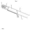
- Fig. 1 shows an exemplary femoral head implant.
- the implant consists of a support screw A, a rectangular slide box B and a likewise rectangular or rectangular cross-section anchor C, which are slidably mounted one inside the other in the direction of the longitudinal axis of the entire arrangement with a small clearance.
- Guide wires 16 are provided for easy positioning of the implant.
- In the sliding box a rectangular passage opening is mounted, which is tuned to the outer contour of the armature.
- the Fig. 2a and 2b show the mounting screw in single views.
- the support screw has a threaded portion 1 and an adjoining Tragschraubenschaft 2.
- the Tragschraubenschaft is shaped substantially cylindrical.
- the thread diameter is about 7 to 13, preferably 10 to 12 millimeters, while the thread length is about 10 to 30, preferably 15 to 25 millimeters.
- the support screw has a continuous longitudinal bore in its entire length. This is connected in the region of the threaded portion with at least one transverse bore 3 and forms a drainage device for pressure reduction in the femoral head. This minimizes the risk of femoral head necrosis, especially in femoral neck fractures, and reduces pressure on fluid accumulation in the femoral head.
- an auto-cutter for the bone thread is formed.
- a turning tool when screwing the support screw is arranged at the other end of the Tragschraubenschaftes hexagon socket 5.
- a hidden inner thread 5a is provided in the longitudinal bore within the Tragschraubenschaftes behind the hexagon socket.
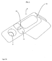
- FIGS. 3a and 3b show the sliding box B in different views.
- the sliding block has a rectangular, provided with Rundungsfasen in the corner areas anchor seat 6 for sliding guidance of the armature C on. He has at the distal end of an anatomical chamfer 7.
- a fastening tab 8 is provided with a bore 9 through which fastening means, for example bone screws, these the cortical bone can be introduced into the bone.
- the slide box each has a guide groove 10 arranged on the rectangular narrow sides outside the anchor receiving opening for receiving one guide wire 16 each.
- the fastening tab 8 can be formed by a predetermined bending point 11 intraoperatively to the individually present bone shape.
- the sliding surface of the tray located in the bone may be provided with an osteophilic structure and / or coated with osteophilic and / or antibiotic substances.
- Fig. 4a shows an exemplary armature C.
- the armature consists of a tip section 12 with cutting edges 12a and a sliding shaft 13.
- the sliding shaft is dimensioned so that it is slidably mounted in the anchor seat 6 of the sliding box with a small clearance.
- An anchor bore 14 is used for a sliding mounting of the support bolt shank 2.
- the Gleitschaftau communkontur corresponds to the substantially rectangular, provided with Rundungsfasen shape of the anchor seat. 6
- the U-shaped, formed as a fork tip portion 12 has two guide grooves 15 which serve to receive each of a guide wire 16. These are in alignment with the guide grooves 10 of the sliding box and are located on the outer sides of the fork.
- Fig. 4b shows an exemplary guide wire. This serves for the intraoperative guidance of slide box and anchor as well as a retention of the femoral head fragment after a successful closed reduction on an extension table.
- the position of the slide box and anchor in the axial and ap position is determined at the beginning of the implantation procedure and a safe and standardized surgical technique is ensured.
- the future implant seat is predrilled using surgical guides.
- Carrying screw A, sliding box B and anchor C are in accordance with Fig. 1 pushed into each other, wherein the support screw is inserted at its Tragschraubenschaft in the anchor hole so that the threaded portion of the support screw is in the region of the tip portion of the armature.
- the armature is slid over its sliding shaft into the anchor seat of the slide box so that the tip portion of the anchor is on the mounting tab of the slide box opposite end of the slide box and the bevelled ends of armature and sliding parallel.
- the guide wires are inserted self-drilling through a surgical template and the implant is placed along the mentioned guide grooves in the bone. Then, the screw is screwed as far as possible into the femoral head and then the anchor so far advanced until it stops, so that it rests on the thread. Subsequently, the support screw and the anchor are pulled back together and compress the fracture zone.
- a compression screw or a compression instrument is screwed into the internal thread of the Tragschraubenschaftes and pulled back with the screw, the head fragment.
- the length of the threaded portion of the backing screw and the length of the tip portion of the anchor are sized so that when the implant is withdrawn intraoperatively during fracture gap compression or postoperatively, when the fracture is sintered, both implant pieces slide together in the axial direction.
- the thread of the mounting screw does not fit through the anchor hole and thus takes the anchor in its sliding movement in the sliding box.
- the slide box can be used by means of a nail as a power carrier for mounting bolt and anchor.
- the attachment tab of the sliding box can be extended as required for extramedullary osteosynthesis or Um einsosteotomien of hip fractures near fractures or misalignments.
- Slideway reducing or canceling devices are particularly useful for possibly eliminating dynamization.
- An example in this regard is in Fig. 5a shown.
- One of the form and size the slide shaft 13 corresponding punch-shaped extension 17 with a blocking plate 18 is inserted into the lateral opening of the anchor seat and thereby abuts against the tapered lateral end of the sliding shaft of the anchor in the sliding box.
- the blocking plate is fixed with one screw 18a in the extension 17 or in a hole at the predetermined bending point 11 of the fastening tab.
- the blocking plate 18 can be screwed without extension 17 and thereby stiffen the predetermined bending point 11.
- a femoral head adapter 20 is possible.
- a second minimally invasive procedure may treat this complication with a femoral head replacement and avoid the much more traumatic intervention of metal removal followed by endoprosthetic replacement.
- Fig. 5b shows an example in this regard.
- a H CosmeticKKadapter 20 is introduced into the sliding box B.
- the arrangement thus formed serves as a hip joint endoprosthesis.
- the adapter has below the ball head 20a on a circumferential collar 19 which is supported on the sliding box.
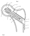
- Fig. 6 shows that in the Figures 1 to 4a
- the threaded portion 1 of the support screw A and the tip portion 12 of the armature C is located with its cutting 12a beyond the fracture line described implant in its position in a femoral head 21 with a fracture line.
- the sliding box B is introduced so that the mounting bracket 8 rests flat on the cortical bone through the bevel 7.
- Fig. 7 shows the in Fig. 5b shown femoral head adapter 20 with sliding box B in its position.
- the sliding box B is here as shown Fig. 6 introduced.
- the original beyond the fracture gap in the proximal Direction located necrotic part of the femoral head was removed along with the original propeller and the original anchor. Instead of the original anchor off Fig. 6
- the H-kopfadapter shown 20 is used with an artificial hip ball 20a in the remaining in the bone sliding box.
- Fig. 8 shows a combination of the implant example of the invention from the previous figures with an intramedullary nail 23.
- the sliding box is driven through an opening of the intramedullary nail into the femoral neck and stabilized and fixed in intramedullary nail.
Description
Die Erfindung betrifft ein Femurkopf-Implantat nach dem Oberbegriff des Anspruchs 1.The invention relates to a femoral head implant according to the preamble of
Zur Versorgung von Frakturen des Oberschenkelhalses bzw. zur Implantation künstlicher Femurköpfe sind aus dem Stand der Technik eine Reihe von Lösungen bekannt. Insbesondere sind dies singuläre Schrauben, Schrauben in Verbindung mit Gleitlaschen und eventuell zusätzlich eingebrachten Klingen in verschiedenen Varianten und proximale Femurnägel.For the treatment of fractures of the femoral neck or for the implantation of artificial femoral heads, a number of solutions are known from the prior art. In particular, these are singular screws, screws in conjunction with Gleitlaschen and possibly additionally introduced blades in different variants and proximal femoral nails.
Singulare Schrauben dienen dabei sowohl als Stützschrauben für den versorgten Oberschenkelhals, als auch zu dessen Frakturkomprimierung. Dieser relativ starre Aufbau gewährleistet jedoch keine Dynamisierung der so ausgeführten Frakturbehandlung, d.h. dass das Implantat im wesentlichen keine Gleitmöglichkeit aufweist. Zudem weist ein derartiges Implantat vor allem in osteoporotischen Knochenstrukturen eine nur geringe Stabilität auf. Zudem ist bei der Implantation derartiger Schrauben ein mehr oder weniger streng paralleles Einbringen von mindestens zwei, zweckmäßigerweise aber drei getrennten Implantaten notwendig. Dies gestaltet sich in der chirurgischen Praxis mitunter als äußerst schwierig und ist oft nicht realisierbar.Singular screws serve as support screws for the treated femoral neck as well as for its fracture compression. However, this relatively rigid construction does not ensure dynamization of the fracture treatment so executed, i. that the implant has substantially no Gleitmöglichkeit. In addition, such an implant, especially in osteoporotic bone structures on only low stability. In addition, in the implantation of such screws a more or less strictly parallel introduction of at least two, but expediently three separate implants is necessary. This sometimes turns out to be extremely difficult in surgical practice and is often unrealizable.
Um diesem Problem zu begegnen, wurden nach dem Stand der Technik Implantate in Form von Tragschrauben in Verbindung mit Gleitlaschen vorgeschlagen. Ein derartiges Implantat wird beispielsweise in der deutschen Patentschrift
Beim Eindrehen der Tragschraube in den Hüftkopf tritt ein Drehmoment auf, das den Hüftkopf versucht ebenfalls in Drehbewegung zu versetzen. Nach der Operation ist der Hüftkopf auf dem Schraubengewinde nicht hinreichend gegen Verdrehen gesichert. Bei der Belastung der Implantatzone tritt außerdem ein großes Kippmoment auf die Lasche auf. Um unter diesen Bedingungen eine ausreichende Stabilität der Osteosynthese im Frakturbereich zu gewährleisten, müssen in der Regel zusätzliche Implantate, zum Beispiel eine oder mehrere Antirotationsschrauben oder Trochanterabstützplatten bei pertrochanteren Frakturen, eingebracht werden. Dadurch erhöht sich der Invasionsgrad im Bereich des behandelten Knochenbereiches. Außerdem weisen derartige Implantate meist vorgegebene Winkelgeometrien auf, die mitunter zu einer individuellen Anatomie, insbesondere einem individuellen CCD-Winkel oder einer Varus-Valgus-Hüfte, nicht kompatibel gemacht werden können.When screwing the carrying screw into the femoral head, a torque occurs, which also tries to set the femoral head in rotary motion. After surgery, the femoral head on the screw thread is not adequately secured against twisting. When loading the implant zone also occurs a large overturning moment on the tab. In order to ensure sufficient stability of osteosynthesis in the fracture area under these conditions, additional implants, for example one or more anti-rotation screws or Trochanterabstützplatten for pertrochanteric fractures must be introduced usually. This increases the degree of invasion in the area of the treated bone area. In addition, such implants usually have predetermined angular geometries, which sometimes can not be made compatible with an individual anatomy, in particular an individual CCD angle or a varus valgus hip.
Bei den aus dem Stand der Technik bekannten Lösungen unter Verwendung proximaler Femur-Nägel, die beispielhaft in der Druckschrift
Bei einer Verwendung einer Klinge, die durch Schläge vorgetrieben wird, besteht keine Kompressionsmöglichkeit bei der Behandlung von Schenkelhalsfrakturen. Vielmehr wird das Kopf-Halsfragment im Bereich der Fraktur beim Eindringen der Klinge auseinandergetrieben und es besteht die Gefahr einer bleibenden Vergrößerung des Frakturspaltes.When using a blade which is driven by blows, there is no possibility of compression in the treatment of femoral neck fractures. Rather, the head and neck fragment is driven apart in the area of the fracture during penetration of the blade and there is a risk of permanent enlargement of the fracture gap.
Zudem ist die Kombination mit einem Marknagel sehr invasiv, weil drei Zugänge durch das Weichteilgewebe eingebracht werden müssen.In addition, the combination with an intramedullary nail is very invasive, because three accesses must be introduced through the soft tissue.
Zum Stand der Technik sei noch auf die
Aus der
Die gattungsbildende
Es ergibt sich aus dem Genannten die Aufgabe, ein Femurkopf-Implantat anzugeben, bei dem minivalinvasiv und kopferhaltend eine rotationsstabile und gleichzeitig kompressionsfähige Frakturbehandlung möglich ist. Optional soll darüber hinaus auch eine Möglichkeit geschaffen werden, im Falle einer Hüftkopfnekrose einen künstlichen Femurkopfersatz einzusetzen. Schließlich soll das geforderte Implantat-System auch für eine Korrekturosteotomie verwendbar sein.It follows from the above-mentioned object to specify a femoral head implant in which a minimally invasive and head holding a rotationally stable and at the same time compressible fracture treatment is possible. Optionally, in addition, a possibility should be created to use in case of Hüftkopfnekrose an artificial femoral head replacement. Finally, the required implant system should also be usable for a corrective osteotomy.
Die Aufgabe wird mit einem Femurkopf-Implantat mit den Merkmalen des Anspruchs 1 gelöst, wobei die Unteransprüche zweckmäßige bzw. vorteilhafte Ausführungsformen des erfindungsgemäßen Gegenstandes beinhalten.The object is achieved with a femoral head implant having the features of
Das Fermurkopf-Implantat zeichnet sich durch eine Anordnung aus einem im wesentlichen in Richtung der Oberschenkelhals-Achse orientierten Kraftträger, einen innerhalb des Kraftträgers in dessen Längsrichtung gleitend gelagerten Anker und einer innerhalb des Ankers gleitend gelagerten, in Richtung der Femurkopf-Achse eingeschraubten Tragschraube aus.The Fermurkopf implant is characterized by an arrangement of an essentially oriented in the direction of the femoral neck axis of force, an inside the power carrier in the longitudinal direction slidably mounted armature and a sliding within the armature, screwed in the direction of the femoral head support screw.
In dem Femurkopf-Implantat ist somit die gleitende Verschiebbarkeit zwischen Tragschraube und Anker, sowie zwischen Anker und Kraftträger mit der durch die Tragschraube bewirkten Kompressionsmöglichkeit und der durch den Formschluss zwischen Anker und Kraftträger bewirkten Rotationssicherung vereinigt. Der Anker übernimmt dabei in Verbindung mit dem Kraftträger die bekannte Funktion der rotationsgesicherten Klinge, während die Tragschraube in Verbindung mit dem Anker und einem zusätzlichen Instrument intraoperativ die Kompressionsmöglichkeit des Frakturspaltes gewährleistet.In the femoral head implant thus the sliding displacement between the support screw and anchor, as well as between armature and power carrier is combined with the compression provided by the support screw compression and caused by the positive connection between the armature and power carrier rotation assurance. The anchor takes over in conjunction with the power carrier, the known function of the rotation-secured blade, while the support screw in conjunction with the anchor and an additional instrument intraoperatively ensures the possibility of compression of the fracture gap.
Durch die Ausrichtung aller Teile des Implantates in die Richtung der Schenkelhals-Achse und eine erfindungsgemäße Rechteckquerschnittsform von Kraftträger und Anker ist bei der Einbringung des Implantates nur ein einziger, verhältnismäßig kleiner Zugang für eine kopferhaltende Osteosynthese der Schenkelhalsfraktur unter weitgehender Schonung der Weichteile möglich. Es kann eine einzelne Tragschraube mit einem verhältnismäßig großen Durchmesser anstelle mehrerer Befestigungsmittel verwendet werden, wobei der Zugang zum Implantationsgebiet auf eine minimalinvasive Weise erfolgt.By aligning all parts of the implant in the direction of the femoral neck axis and a rectangular cross-sectional shape of force carrier and anchor according to the invention only a single, relatively small access for a head-holding osteosynthesis of the femoral neck fracture with extensive protection of the soft tissues is possible when introducing the implant. A single relatively large diameter support screw may be used instead of multiple attachment means, with access to the implantation area in a minimally invasive manner.
In einer Ausführungsform weist die Tragschraube einen Gewindeabschnitt und einen zylindrischen Tragschraubenschaft mit einer axialen Längsbohrung und mindestens einer im Bereich des Gewindeabschnitts angeordneten Querbohrung auf. Der Tragschraubenschaft bildet dabei den im Anker gleitfähigen Teil der Schraube, während der Gewindeabschnitt in das Knochengewebe hineingedreht wird. Die Querbohrungen dienen in Verbindung mit der Längsbohrung vor allem als Drainageöffnungen.In one embodiment, the support screw has a threaded portion and a cylindrical Tragschraubenschaft with an axial longitudinal bore and at least one arranged in the region of the threaded portion transverse bore. The Tragschraubenschaft forms the slidable in the anchor part of the screw, while the threaded portion is screwed into the bone tissue. The cross bores serve in connection with the longitudinal bore mainly as drainage openings.
Der zylindrische Tragschraubenschaft weist zweckmäßigerweise einen distalen Innensechskant zur Aufnahme eines Drehwerkzeuges auf. Zusätzlich dazu weist der zylindrische Tragschraubenschaft ein Innengewinde zum Eindrehen einer Kompressionsschraube bzw. eines Kompressionsinstrumentes auf.The cylindrical Tragschraubenschaft expediently has a distal hexagon socket for receiving a rotary tool. In addition, the cylindrical Tragschraubenschaft has an internal thread for screwing a compression screw or a Kompressionsinstrumentes.
Erfindungsgemäß ist der Kraftträger als ein Gleitkasten mit einer Gleitkastenaufnahme und einer extramedullären Befestigungslasche ausgebildet. Die Gleitkastenaufnahme dient der gleitenden Aufnahme des Ankers, die Befestigungslasche der extramedullären Befestigung des Gleitkastens.According to the invention, the force carrier is designed as a sliding box with a sliding box receptacle and an extramedullary fastening strap. The sliding box holder is used for sliding reception of the anchor, the attachment tab of the extramedullary attachment of the sliding box.
Die Befestigungslasche weist dabei mindestens eine Bohrung zum Einbringen eines Befestigungsmittels, insbesondere einer Knochenschraube, auf.The fastening tab has at least one bore for introducing a fastening means, in particular a bone screw on.
Zusätzlich dazu ist die Befestigungslasche erfindungsgemäß mit mindestens einer Sollbiegestelle für intraoperatives Anformen versehen. Dadurch ist die Befestigungslasche auf die individuell vorliegende Femurform anmodellierbar.In addition, the fastening strap according to the invention is provided with at least one predetermined bending point for intraoperative molding. As a result, the fastening strap can be modeled on the individually present femoral shape.
Für extramedulläre Osteosynthesen und/oder Umstellungsosteotomien bei hüftgelenksnahem Frakturen und/oder Fehlstellungen weist die Befestigungslasche eine dafür erforderliche vergrößerte Länge auf.For extramedullary osteosynthesis and / or Umkehrosteotomien in hip fractures near fractures and / or misalignments, the mounting tab has a required for increased length.
Der Gleitkasten ist bei einer vorteilhaften erfindungsgemäßen Ausgestaltung mit mindestens einer, vorzugsweise zwei Führungsausformungen, insbesondere einer, vorzugsweise zwei Führungsrinnen oder Führungsbohrungen, zum Einführen mindestens eines Führungsdrahtes vorgesehen. Der Gleitkasten kann dadurch genau positioniert werden.The sliding box is provided in an advantageous embodiment of the invention with at least one, preferably two Führungsausformungen, in particular one, preferably two guide grooves or guide holes, for introducing at least one guide wire. The sliding box can be positioned precisely.
Bei einer weiteren Ausführungsform ist die Aufnahme des Kraftträgers als ein intramedullärer Nagel ausgebildet.In a further embodiment, the receptacle of the force carrier is designed as an intramedullary nail.
Der Anker weist bei einer Ausführungsform einen distalen Gleitschaft und einen proximalen verbreiterten Spitzenabschnitt mit einer durch den Gleitschaft verlaufenden Bohrung zur Aufnahme des Tragschraubenschaftes auf. Der distale Gleitschaft ist für eine gleitende Bewegung im Kraftträger, insbesondere im Gleitkasten, vorgesehen, während die Bohrung im Gleitschaft den Tragschraubenschaft gleitend aufnimmt.The anchor in one embodiment has a distal sliding shaft and a proximal widened tip section with a bore extending through the sliding shaft for receiving the carrier shaft. The distal sliding shaft is provided for a sliding movement in the power carrier, in particular in the sliding box, while the bore in the sliding shaft slidably receives the carrier screw shaft.
Der Spitzenabschnitt weist mindestens eine mit der Führungsausformung am Gleitkasten fluchtende Ankerführung, insbesondere mindestens eine Ankerführungsrinne, auf. Dadurch können beim Einsetzen des Implantates Gleitkasten und Anker genau positioniert werden.The tip portion has at least one aligned with the Führungsausformung on the slide box anchor guide, in particular at least one Anchor guide trough, on. This allows the slide box and anchor to be precisely positioned when inserting the implant.
Zusätzlich kann eine den Gleitweg des Ankers verkürzende, insbesondere aufhebende, Blockiervorrichtung zum Einschieben und Befestigen in den Kraftträger, insbesondere den Gleitkasten, vorgesehen sein. Dadurch wird die Dynamisierbarkeit des Implantates falls erforderlich aufgehoben.In addition, a shortening the glide path of the armature, in particular lifting, blocking device for insertion and fastening in the power carrier, in particular the sliding box, may be provided. As a result, the dynamizability of the implant is canceled if necessary.
Die Blockiervorrichtung ist bei einer Ausführungsform als eine stempelförmige Verlängerung mit einem Blockierungsplättchen ausgebildet. Das Blockierungsplättchen ist zweckmäßigerweise an der extramedullären Befestigungslasche arretierbar, insbesondere mit einem Befestigungsmittel fixierbar.The blocking device is formed in one embodiment as a punch-shaped extension with a blocking plate. The blocking plate is expediently lockable on the extramedullary fastening strap, in particular fixable with a fastening means.
Weiterhin kann bei einer zweckmäßigen Ausführungsform der Anker in Form eines Hüftkopfadapters ausgebildet sein, wobei dieser im Bereich des Spitzenabschnitts einen Hüftkopfabschnitt aufweist. In diesem Fall ist zwischen dem Hüftkopfabschnitt und dem Gleitschaft ein Kragenabschnitt für eine abstützende Lagerung des Hüftkopfadapters auf dem Kraftträger vorgesehen.Furthermore, in an expedient embodiment, the armature can be designed in the form of a femoral head adapter, wherein this armature has a femoral head section in the region of the tip section. In this case, a collar portion for supporting support of the femoral head adapter on the force carrier is provided between the femoral head portion and the sliding shaft.
Das Femurkopf-Implantat weist in einer vorteilhaften erfindungsgemäßen Ausgestaltung zusätzlich auf der das Knochengewebe berührenden Oberfläche des Gleitkastens eine osteophile Struktur und/oder eine osteophile und/oder antibiotische Beschichtung auf. Diese verbessert die Osteosynthese in der unmittelbaren Umgebung des Implantates.In an advantageous embodiment according to the invention, the femoral head implant additionally has an osteophilic structure and / or an osteophilic and / or antibiotic coating on the surface of the sliding box which contacts the bone tissue. This improves the osteosynthesis in the immediate vicinity of the implant.
Weiterhin weist der Gewindeabschnitt der Tragschraube mindestens eine Querbohrung in Verbindung mit einer innerhalb der Tragschraube verlaufenden axialen Längsbohrung aufweist. Dadurch wird ein Drainagekanal zum Ableiten von sich im Hüftkopf ansammelnder Flüssigkeit gebildet.Furthermore, the threaded portion of the support screw has at least one transverse bore in connection with an axial longitudinal bore extending within the support screw. As a result, a drainage channel is formed for draining fluid accumulating in the femoral head.
Der Gewindeabschnitt der Tragschraube weist an dessen Spitze mindestens eine Einfräsung zur Ausbildung einer Selbstschneide auf. Hierdurch wird der Vortrieb in das Knochengewebe erleichtert, wobei das Knochengewinde durch den Gewindekopf eingeschnitten wird.The threaded portion of the support screw has at its tip at least one milled recess to form an auto-cutting. As a result, the propulsion is facilitated in the bone tissue, wherein the bone thread is cut through the threaded head.
Das Femurkopf-Implantat soll im Folgenden anhand von Ausführungsbeispielen näher erläutert werden. Zur Verdeutlichung dienen die
Es zeigt:
-
Fig. 1 eine beispielhafte Anordnung aus Tragschraube, Anker und Gleitkasten mit einer extramedullären Befestigung am Femurschaft, -
Fig. 2a eine erste Ansicht der Tragschraube, -
Fig. 2b eine zweite Ansicht der Tragschraube mit einer Darstellung des Innensechskants, -
Fig. 3a eine Seitenansicht des Gleitkastens, -
Fig. 3b eine Ansicht des Gleitkastens mit einer Darstellung der Gleitkastenaufnahme und der Sollbiegestelle der Befestigungslasche, -
Fig. 4a eine Seitenansicht des Ankers mit Gleitschaft und Spitze, -
Fig. 4b einen beispielhaften Führungsdraht, -
Fig. 5a eine beispielhafte Blockiervorrichtung zur Gleitwegverkürzung bzw.-aufhebung, -
Fig. 5b eine Darstellung eines Hüftkopfadapters und dessen Zusammenbau mit dem Gleitkasten, -
Fig. 6 eine Ansicht des Femurkopfimplantats in einer extramedullären Position, -
Fig. 7 eine Ansicht des Hüftkopfadapters mit Gleitkasten ausFig. 5b in einer extramedullären Position, -
Fig. 8 eine Ansicht des Femurkopfimplantats in Verbindung mit einem Marknagel zur intramedullären Kraftaufnahme.
-
Fig. 1 an exemplary arrangement of support screw, anchor and slide box with an extramedullary attachment to the femoral shaft, -
Fig. 2a a first view of the bearing screw, -
Fig. 2b a second view of the bearing screw with a representation of the hexagon socket, -
Fig. 3a a side view of the sliding box, -
Fig. 3b a view of the sliding box with a representation of the Gleitkastenaufnahme and the predetermined bending point of the fastening tab, -
Fig. 4a a side view of the anchor with Gleitschaft and tip, -
Fig. 4b an exemplary guidewire, -
Fig. 5a an exemplary blocking device for Gleitwegverkürzung or suspension, -
Fig. 5b a representation of a femoral head adapter and its assembly with the sliding box, -
Fig. 6 a view of the femoral head implant in an extramedullary position, -
Fig. 7 a view of the femoral head adapter with sliding boxFig. 5b in an extramedullary position, -
Fig. 8 a view of the femoral head implant in conjunction with an intramedullary force intramedullary nail.
Die
Die Tragschraube weist in ihrer gesamten Länge eine durchgehende Längsbohrung auf. Diese ist im Bereich des Gewindeabschnittes mit mindestens einer Querbohrung 3 verbunden und bildet eine Drainageeinrichtung zur Druckminderung im Hüftkopf aus. Damit wird das Risiko einer Hüftkopfnekrose, insbesondere bei Schenkelhalsfrakturen, minimiert und ein Druckabbau bei Ansammlung von Flüssigkeit im Hüftkopf bewirkt.The support screw has a continuous longitudinal bore in its entire length. This is connected in the region of the threaded portion with at least one
Durch eine oder mehrere von Einfräsungen 4 auf dem Gewinde ist eine Selbstschneide für das Knochengewinde ausgebildet. Zum Eingreifen eines Drehwerkzeugs beim Vorschrauben der Tragschraube dient ein am anderen Ende des Tragschraubenschaftes angeordneter Innensechskant 5. Zum Eindrehen einer Kompressionsschraube oder eines anderen Kompressionsinstrumentes ist in der Längsbohrung innerhalb des Tragschraubenschaftes hinter dem Innensechskant ein hier verdecktes Innengewinde 5a vorgesehen.By one or more of milled 4 on the thread an auto-cutter for the bone thread is formed. For engaging a turning tool when screwing the support screw is arranged at the other end of the
Die
Der Gleitkasten weist je eine an den Rechteck-Schmalseiten außerhalb des Ankeraufnahmedurchbruchs angeordnete Führungsrinne 10 zur Aufnahme je eines Führungsdrahtes 16 auf. Außerdem ist die Befestigungslasche 8 über eine Sollbiegestelle 11 intraoperativ an die individuell vorliegende Knochenform anformbar. Für eine verbessere Osteointegration kann die im Knochen befindliche Oberfläche des Gleitkastens mit einer osteophilen Struktur versehen und/oder mit osteophilen und/oder antibiotischen Substanzen beschichtet sein.The slide box each has a
Der U-förmige, als Gabel ausgebildete Spitzenabschnitt 12 weist zwei Führungsrinnen 15 auf, die der Aufnahme je eines Führungsdrahtes 16 dienen. Diese liegen in Flucht mit den Führungsrinnen 10 des Gleitkastens und befinden sich an den Außenseiten der Gabel.The U-shaped, formed as a
Bei einer Verwendung von zwei Führungsdrähten wird zu Beginn des Implantationseingriffs die Lage von Gleitkasten und Anker in axialer und ap-Lage festgelegt und eine sichere und standardisierte Operationstechnik gewährleistet. Hierzu wird über Bohrschablonen der zukünftige Implantatsitz vorgebohrt. Tragschraube A, Gleitkasten B und Anker C werden gemäß
Die Führungsdrähte werden selbstbohrend über eine Bohrschablone eingesetzt und das Implantat wird entlang der erwähnten Führungsrinnen in den Knochen eingebracht. Dann wird die Tragschraube so weit wie möglich in den Femurkopf eingedreht und anschließend der Anker bis zum Anschlag so weit vorgetrieben, dass er auf dem Gewinde aufsitzt. Anschließend werden die Tragschraube und der Anker gemeinsam zurück gezogen und komprimieren dabei die Frakturzone. Hierzu wird eine Kompressionsschraube oder ein Kompressionsinstrument in das Innengewinde des Tragschraubenschaftes eingedreht und mit der Schraube das Kopffragment zurückgezogen.The guide wires are inserted self-drilling through a surgical template and the implant is placed along the mentioned guide grooves in the bone. Then, the screw is screwed as far as possible into the femoral head and then the anchor so far advanced until it stops, so that it rests on the thread. Subsequently, the support screw and the anchor are pulled back together and compress the fracture zone. For this purpose, a compression screw or a compression instrument is screwed into the internal thread of the Tragschraubenschaftes and pulled back with the screw, the head fragment.
Die Länge des Gewindeabschnitts der Tragschraube und die Länge des Spitzenabschnitts des Ankers sind so bemessen, dass beim Zurückziehen des Implantats intraoperativ bei der Frakturspaltkompression oder postoperativ beim Sintern der Fraktur beide Implantatteile gemeinsam in axialer Richtung gleiten. Das Gewinde der Tragschraube passt nicht durch die Ankerbohrung und nimmt somit den Anker bei dessen Gleitbewegung im Gleitkasten mit.The length of the threaded portion of the backing screw and the length of the tip portion of the anchor are sized so that when the implant is withdrawn intraoperatively during fracture gap compression or postoperatively, when the fracture is sintered, both implant pieces slide together in the axial direction. The thread of the mounting screw does not fit through the anchor hole and thus takes the anchor in its sliding movement in the sliding box.
Bei den beschriebenen Ausführungsbeispielen können eine Reihe von Abänderungen vorgenommen werden. So kann der Gleitkasten mittels eines Nagels als Kraftträger für Tragschraube und Anker eingesetzt werden.In the described embodiments, a number of modifications can be made. Thus, the slide box can be used by means of a nail as a power carrier for mounting bolt and anchor.
Die Befestigungslasche des Gleitkastens kann für extramedulläre Osteosynthesen bzw. Umstellungsosteotomien von hüftgelenksnahen Frakturen bzw. Fehlstellungen beliebig verlängert sein.The attachment tab of the sliding box can be extended as required for extramedullary osteosynthesis or Umstellungsosteotomien of hip fractures near fractures or misalignments.
Besonders zweckmäßig für eine möglicherweise erforderliche Aufhebung der Dynamisierung sind gleitwegsvermindernde oder -aufhebende Vorrichtungen. Ein diesbezügliches Beispiel ist in
Bei Bedarf, zum Beispiel zur extramedullären Versorgung einer instabiler Fraktur mit einer langen Befestigungslasche am Gleitkasten, kann das Blockierungsplättchen 18 auch ohne Verlängerung 17 aufgeschraubt werden und dabei die Sollbiegestelle 11 versteifen.If required, for example, for extramedullary supply of an unstable fracture with a long mounting strap on the slide box, the blocking plate 18 can be screwed without
Weiterhin ist auch das Aufsetzen eines Hüftkopfadapters 20 möglich. Bei einer entsprechenden Indikation, z.B. bei einem geriatrischen Patienten mit einer als Komplikation nach der Versorgung der Oberschenkelhalsfraktur eintretenden Hüftkopfnekrose, kann durch einen zweiten minimalinvasiven Eingriff diese Komplikation durch einen Hüftkopfersatz behandelt und der wesentlich größere traumatisierendere Eingriff der Metallentfernung bei anschließendem endoprothetischen Ersatz vermieden werden.
Bei diesem Beispiel wird in den Gleitkasten B ein Hüftkopfadapter 20 eingebracht. Die so gebildete Anordnung dient als Hüftgelenkendoprothese. Der Adapter weist unterhalb des Kugelkopfes 20a einen umlaufenden Kragen 19 auf, der sich auf dem Gleitkasten abstützt.In this example, a
Weitere Ausführungsformen ergeben sich aus den Unteransprüche bzw. durch Ausgestaltungen der dargestellten Ausführungsbeispiele im Rahmen fachmännischen Handelns.Further embodiments will become apparent from the dependent claims or by embodiments of the illustrated embodiments in the context of expert action.
- AA
- Tragschraubesupport screw
- 11
- Gewindeabschnittthreaded portion
- 22
- TragschraubenschaftSupporting screw shaft
- 33
- Querbohrungcross hole
- 44
- Einfräsungmilled
- 55
- InnensechskantAllen
- 5a5a
- Innengewinde (verdeckt)Internal thread (hidden)
- BB
- Gleitkastenslide box
- 66
- Ankeraufnahmeanchor recording
- 77
- Abschrägungbevel
- 88th
- Befestigungslaschemounting tab
- 99
- Bohrungdrilling
- 1010
- Führungsrinneguide trough
- 1111
- SollbiegestellePredetermined bending point
- CC
- Ankeranchor
- 1212
- Spitzenabschnitttip portion
- 12a12a
- Schneidecutting edge
- 1313
- Gleitschaftsliding shaft
- 1414
- Ankerbohrunganchor hole
- 1515
- Führungsrinne am AnkerGuide trough at the anchor
- 1616
- Führungsdrahtguidewire
- 1717
- stempelförmige Verlängerungstamp-shaped extension
- 1818
- Blockierungsplättchenblocking plates
- 18a18a
- Schraubescrew
- 1919
- umlaufender Kragencircumferential collar
- 2020
- HüftkopfadapterHüftkopfadapter
- 20a20a
- künstliche Hüftkugelartificial hip ball
- 2121
- HüftkopfFemoral Head
- 2222
- Frakturliniefracture line
- 2323
- MarknagelMark Nagel
Claims (14)
- Femoral head implant consisting of an arrangement of a load carrier (B) oriented in the direction of the femoral neck axis, an anchor (C) mounted in a sliding manner inside the load carrier in the longitudinal direction thereof, and a carrier screw (A) mounted in a sliding manner inside the anchor and driven in the direction of the femoral head,
characterized in that
the load carrier is designed as a slide box (B) with a rectangular cross-section, having a rectangular slide box receptacle (6) and an extra-medullary fixing tab (8), and that the anchor (C) has a rectangular cross-section. - Femoral head implant according to claim 1,
characterized in that
the carrier screw (A) comprises a threaded portion (1) and a cylindrical carrier screw shaft (2) having an axial longitudinal hole and at least one cross hole (3) arranged in the area of the threaded portion. - Femoral head implant according to claim 2,
characterized in that
the cylindrical carrier screw shaft (2) comprises a distal hexagon socket (5) for the insertion of a turning tool. - Femoral head implant according to one of claims 2 or 3,
characterized in that
the cylindrical carrier screw shaft (2) comprises an internal thread (5a) for screwing in a compression screw or compression instrument. - Femoral head implant according to claim 1,
characterized in that
the fixing tab (8) comprises at least one bore (9) for inserting a fixing means, in particular a bone screw. - Femoral head implant according to one of claims 1 or 5,
characterized in that
the fixing tab (8) comprises at least one predetermined bending point (11) for an inoperative adaptation. - Femoral head implant according to one of claims 1 to 6,
characterized in that
the fixing tab (8) comprises an increased length required for osteosyntheses in the case of fractures of the femoral neck and/or corrective osteotomies in the case of malpositions. - Femoral head implant according to one of claims 1 to 7,
characterized in that
the slide box (B) comprises at least one, preferably two molded guiding portions, in particular one, preferably two guiding grooves (10) or guiding holes for inserting at least one guiding wire (16) on the longitudinal narrow outer sides thereof. - Femoral head implant according to claim 1,
characterized in that
the anchor (C) comprises a distal sliding shaft (13) and a proximal, widened fork-shaped point part (12) including a hole (14) extending through the sliding shaft for receiving in a sliding manner the carrier screw shaft (2). - Femoral head implant according to claim 8 and 9,
characterized in that
the fork-shaped point part (12) comprises at least one, preferably two external anchor guides aligned with the molded guiding portion on the slide box, in particular at least one anchor guiding groove (15). - Femoral head implant according to claim 1,
characterized in that
an inhibiting device shortening, in particular canceling the sliding distance of the anchor (C) is provided for insertion into and fixing in the slide box (B). - Femoral head implant according to one of the preceding claims,
characterized in that
the threaded portion (1) of the carrier screw (A) comprises at least one cross hole (3) in connection with an axial longitudinal hole extending inside the carrier screw. - Femoral head implant according to one of the preceding claims,
characterized in that
the threaded portion (1) of the carrier screw (A) comprises at the point thereof at least one milled portion (4) to create a self-cutting edge. - Femoral head implant according to one of the preceding claims,
characterized in that
the slide box receptacle (6) comprises rounded chamfers in the corner regions.
Applications Claiming Priority (3)
| Application Number | Priority Date | Filing Date | Title |
|---|---|---|---|
| DE102006028449 | 2006-06-21 | ||
| DE102006032811A DE102006032811A1 (en) | 2006-06-21 | 2006-07-14 | Femoral head implant |
| PCT/EP2007/054755 WO2007147688A1 (en) | 2006-06-21 | 2007-05-16 | Femoral head implant |
Publications (2)
| Publication Number | Publication Date |
|---|---|
| EP2029037A1 EP2029037A1 (en) | 2009-03-04 |
| EP2029037B1 true EP2029037B1 (en) | 2013-10-23 |
Family
ID=38521065
Family Applications (1)
| Application Number | Title | Priority Date | Filing Date |
|---|---|---|---|
| EP07729203.5A Active EP2029037B1 (en) | 2006-06-21 | 2007-05-16 | Femoral head implant |
Country Status (3)
| Country | Link |
|---|---|
| EP (1) | EP2029037B1 (en) |
| DE (1) | DE102006032811A1 (en) |
| WO (1) | WO2007147688A1 (en) |
Families Citing this family (2)
| Publication number | Priority date | Publication date | Assignee | Title |
|---|---|---|---|---|
| DE102007061550A1 (en) | 2006-07-14 | 2009-07-30 | Königsee Implantate und Instrumente zur Osteosynthese GmbH | Femoral head implant for use during osteosynthesis of femoral neck fracture, has double T-section with perpendicular sections that are cannulated and are formed for guidance of carrier screw with slots for reciprocal guidance of anchor |
| DE102014113556A1 (en) * | 2014-09-19 | 2016-03-24 | Königsee Implantate GmbH | Osteosynthesis aids for the treatment of subtrochanteric fractures and / or pertrochanteric fractures and / or femoral neck fractures |
Family Cites Families (11)
| Publication number | Priority date | Publication date | Assignee | Title |
|---|---|---|---|---|
| US2612159A (en) * | 1949-03-01 | 1952-09-30 | Marie B Collison | Trochanteric plate for bone surgery |
| US2682265A (en) * | 1951-12-28 | 1954-06-29 | Marie B Collison | Trochanteric plate and artificial femoral head |
| US3530854A (en) * | 1968-07-11 | 1970-09-29 | John Kearney | Fracture nail assembly |
| US4657001A (en) * | 1984-07-25 | 1987-04-14 | Fixel Irving E | Antirotational hip screw |
| FR2595565B2 (en) * | 1985-07-10 | 1994-08-12 | Cirotteau Yves | TOTAL HIP PROSTHESIS WITH EXTERNAL CORTICAL SUPPORT |
| US5087260A (en) * | 1989-09-15 | 1992-02-11 | Fixel Irving E | Total femoral hip system |
| CH681595A5 (en) * | 1990-03-19 | 1993-04-30 | Synthes Ag | |
| DE4318150C2 (en) * | 1993-06-01 | 1996-08-01 | Endocare Ag | Osteosynthesis tools for the treatment of subtrochanteric and pertrochanteric fractures as well as fractures of the femoral neck |
| DE4438620A1 (en) * | 1994-05-02 | 1995-11-09 | Laghaollah Dr Elhami | Joint prosthesis and device for making a bore in at least one joint head |
| US5749872A (en) * | 1995-09-08 | 1998-05-12 | Ace Medical Company | Keyed/keyless barrel for bone plates |
| DE50312145D1 (en) * | 2003-09-18 | 2009-12-31 | Synthes Gmbh | DEVICE FOR TREATING FRACTURES OF THE FEMUR |
-
2006
- 2006-07-14 DE DE102006032811A patent/DE102006032811A1/en not_active Ceased
-
2007
- 2007-05-16 EP EP07729203.5A patent/EP2029037B1/en active Active
- 2007-05-16 WO PCT/EP2007/054755 patent/WO2007147688A1/en active Application Filing
Also Published As
| Publication number | Publication date |
|---|---|
| DE102006032811A1 (en) | 2008-01-03 |
| WO2007147688A1 (en) | 2007-12-27 |
| EP2029037A1 (en) | 2009-03-04 |
Similar Documents
| Publication | Publication Date | Title |
|---|---|---|
| DE10348932B4 (en) | System for the minimally invasive treatment of a proximal humeral or femoral fracture | |
| DE60206639T2 (en) | DEVICE FOR THE PERCUTUAL SAFETY OF A BONE PLATE | |
| EP1682020B1 (en) | Bone fixing device | |
| EP1024762B1 (en) | Bone fixation device | |
| EP1681024B1 (en) | Bone anchor element | |
| EP2152173B1 (en) | Locking intramedullary nail | |
| DE60213800T2 (en) | Nail and screw for surgical fixation system | |
| EP0514662B1 (en) | Surgery device to position osteosynthesis fixation elements, particularly bone screws | |
| EP0736286A2 (en) | Osteosynthetic device for treating subtrochanteric and pertrochanteric fractures and fractures of the neck of the femur | |
| WO1999062417A1 (en) | Surgical blind rivet with closing element | |
| EP1725177A1 (en) | Resetting tool | |
| EP2510892B1 (en) | Surgical distraction instrument for laminoplasty | |
| DE102019000965B4 (en) | Bone anchoring device for pedicle access | |
| AT509852A4 (en) | FLEXIBLE HUMERUS NAIL | |
| DE10335388A1 (en) | Surgical reference device, comprising bone plate attached to femur for safe joining of rigid body | |
| EP2029037B1 (en) | Femoral head implant | |
| DE102007029090A1 (en) | Device for osteosynthesis, particularly bone fracture near joint, has pin for implantation into abarticular bone, and proximal longitudinal ring element provided for implantation into bone fragment near joint | |
| EP1974681B1 (en) | Implant set | |
| DE60036553T2 (en) | FEMORAL INTERMEDULLARY STABS SYSTEM | |
| EP2750616B1 (en) | Device for fixing a bone fractured in the femoral neck region | |
| DE202007005061U1 (en) | implant set | |
| DE202007019576U1 (en) | Femoral head implant | |
| WO2016083355A1 (en) | Securing element | |
| DE102007061550A1 (en) | Femoral head implant for use during osteosynthesis of femoral neck fracture, has double T-section with perpendicular sections that are cannulated and are formed for guidance of carrier screw with slots for reciprocal guidance of anchor | |
| DE202019005511U1 (en) | Bone anchoring device for pedicle access |
Legal Events
| Date | Code | Title | Description |
|---|---|---|---|
| PUAI | Public reference made under article 153(3) epc to a published international application that has entered the european phase |
Free format text: ORIGINAL CODE: 0009012 |
|
| 17P | Request for examination filed |
Effective date: 20081210 |
|
| AK | Designated contracting states |
Kind code of ref document: A1 Designated state(s): AT BE BG CH CY CZ DE DK EE ES FI FR GB GR HU IE IS IT LI LT LU LV MC MT NL PL PT RO SE SI SK TR |
|
| AX | Request for extension of the european patent |
Extension state: AL BA HR MK RS |
|
| 17Q | First examination report despatched |
Effective date: 20120202 |
|
| DAX | Request for extension of the european patent (deleted) | ||
| GRAP | Despatch of communication of intention to grant a patent |
Free format text: ORIGINAL CODE: EPIDOSNIGR1 |
|
| INTG | Intention to grant announced |
Effective date: 20130523 |
|
| GRAS | Grant fee paid |
Free format text: ORIGINAL CODE: EPIDOSNIGR3 |
|
| GRAA | (expected) grant |
Free format text: ORIGINAL CODE: 0009210 |
|
| AK | Designated contracting states |
Kind code of ref document: B1 Designated state(s): AT BE BG CH CY CZ DE DK EE ES FI FR GB GR HU IE IS IT LI LT LU LV MC MT NL PL PT RO SE SI SK TR |
|
| REG | Reference to a national code |
Ref country code: GB Ref legal event code: FG4D Free format text: NOT ENGLISH |
|
| REG | Reference to a national code |
Ref country code: CH Ref legal event code: EP |
|
| REG | Reference to a national code |
Ref country code: AT Ref legal event code: REF Ref document number: 637120 Country of ref document: AT Kind code of ref document: T Effective date: 20131115 |
|
| REG | Reference to a national code |
Ref country code: IE Ref legal event code: FG4D Free format text: LANGUAGE OF EP DOCUMENT: GERMAN |
|
| REG | Reference to a national code |
Ref country code: DE Ref legal event code: R096 Ref document number: 502007012419 Country of ref document: DE Effective date: 20131212 |
|
| REG | Reference to a national code |
Ref country code: CH Ref legal event code: PFA Owner name: KOENIGSEE IMPLANTATE GMBH, DE Free format text: FORMER OWNER: KOENIGSEE IMPLANTATE UND INSTRUMENTE ZUR OSTHEOSYNTHESE GMBH, DE Ref country code: CH Ref legal event code: NV Representative=s name: REUTELER AND CIE S.A., CH |
|
| REG | Reference to a national code |
Ref country code: DE Ref legal event code: R081 Ref document number: 502007012419 Country of ref document: DE Owner name: KOENIGSEE IMPLANTATE GMBH, DE Free format text: FORMER OWNER: KOENIGSEE IMPLANTATE GMBH, 07426 ALLENDORF, DE Effective date: 20131118 Ref country code: DE Ref legal event code: R081 Ref document number: 502007012419 Country of ref document: DE Owner name: KOENIGSEE IMPLANTATE GMBH, DE Free format text: FORMER OWNER: KOENIGSEE IMPLANTATE UND INSTRUMENTE ZUR OSTHEOSYNTHESE GMBH, 07426 ALLENDORF, DE Effective date: 20131106 |
|
| REG | Reference to a national code |
Ref country code: NL Ref legal event code: VDEP Effective date: 20131023 |
|
| REG | Reference to a national code |
Ref country code: LT Ref legal event code: MG4D |
|
| PG25 | Lapsed in a contracting state [announced via postgrant information from national office to epo] |
Ref country code: SE Free format text: LAPSE BECAUSE OF FAILURE TO SUBMIT A TRANSLATION OF THE DESCRIPTION OR TO PAY THE FEE WITHIN THE PRESCRIBED TIME-LIMIT Effective date: 20131023 Ref country code: FI Free format text: LAPSE BECAUSE OF FAILURE TO SUBMIT A TRANSLATION OF THE DESCRIPTION OR TO PAY THE FEE WITHIN THE PRESCRIBED TIME-LIMIT Effective date: 20131023 Ref country code: LT Free format text: LAPSE BECAUSE OF FAILURE TO SUBMIT A TRANSLATION OF THE DESCRIPTION OR TO PAY THE FEE WITHIN THE PRESCRIBED TIME-LIMIT Effective date: 20131023 Ref country code: NL Free format text: LAPSE BECAUSE OF FAILURE TO SUBMIT A TRANSLATION OF THE DESCRIPTION OR TO PAY THE FEE WITHIN THE PRESCRIBED TIME-LIMIT Effective date: 20131023 Ref country code: IS Free format text: LAPSE BECAUSE OF FAILURE TO SUBMIT A TRANSLATION OF THE DESCRIPTION OR TO PAY THE FEE WITHIN THE PRESCRIBED TIME-LIMIT Effective date: 20140223 |
|
| PG25 | Lapsed in a contracting state [announced via postgrant information from national office to epo] |
Ref country code: ES Free format text: LAPSE BECAUSE OF FAILURE TO SUBMIT A TRANSLATION OF THE DESCRIPTION OR TO PAY THE FEE WITHIN THE PRESCRIBED TIME-LIMIT Effective date: 20131023 Ref country code: LV Free format text: LAPSE BECAUSE OF FAILURE TO SUBMIT A TRANSLATION OF THE DESCRIPTION OR TO PAY THE FEE WITHIN THE PRESCRIBED TIME-LIMIT Effective date: 20131023 Ref country code: CY Free format text: LAPSE BECAUSE OF FAILURE TO SUBMIT A TRANSLATION OF THE DESCRIPTION OR TO PAY THE FEE WITHIN THE PRESCRIBED TIME-LIMIT Effective date: 20131023 |
|
| PG25 | Lapsed in a contracting state [announced via postgrant information from national office to epo] |
Ref country code: PT Free format text: LAPSE BECAUSE OF FAILURE TO SUBMIT A TRANSLATION OF THE DESCRIPTION OR TO PAY THE FEE WITHIN THE PRESCRIBED TIME-LIMIT Effective date: 20140224 |
|
| REG | Reference to a national code |
Ref country code: DE Ref legal event code: R097 Ref document number: 502007012419 Country of ref document: DE |
|
| PG25 | Lapsed in a contracting state [announced via postgrant information from national office to epo] |
Ref country code: EE Free format text: LAPSE BECAUSE OF FAILURE TO SUBMIT A TRANSLATION OF THE DESCRIPTION OR TO PAY THE FEE WITHIN THE PRESCRIBED TIME-LIMIT Effective date: 20131023 |
|
| PG25 | Lapsed in a contracting state [announced via postgrant information from national office to epo] |
Ref country code: RO Free format text: LAPSE BECAUSE OF FAILURE TO SUBMIT A TRANSLATION OF THE DESCRIPTION OR TO PAY THE FEE WITHIN THE PRESCRIBED TIME-LIMIT Effective date: 20131023 Ref country code: SK Free format text: LAPSE BECAUSE OF FAILURE TO SUBMIT A TRANSLATION OF THE DESCRIPTION OR TO PAY THE FEE WITHIN THE PRESCRIBED TIME-LIMIT Effective date: 20131023 Ref country code: CZ Free format text: LAPSE BECAUSE OF FAILURE TO SUBMIT A TRANSLATION OF THE DESCRIPTION OR TO PAY THE FEE WITHIN THE PRESCRIBED TIME-LIMIT Effective date: 20131023 Ref country code: IT Free format text: LAPSE BECAUSE OF FAILURE TO SUBMIT A TRANSLATION OF THE DESCRIPTION OR TO PAY THE FEE WITHIN THE PRESCRIBED TIME-LIMIT Effective date: 20131023 Ref country code: PL Free format text: LAPSE BECAUSE OF FAILURE TO SUBMIT A TRANSLATION OF THE DESCRIPTION OR TO PAY THE FEE WITHIN THE PRESCRIBED TIME-LIMIT Effective date: 20131023 |
|
| PLBE | No opposition filed within time limit |
Free format text: ORIGINAL CODE: 0009261 |
|
| STAA | Information on the status of an ep patent application or granted ep patent |
Free format text: STATUS: NO OPPOSITION FILED WITHIN TIME LIMIT |
|
| PG25 | Lapsed in a contracting state [announced via postgrant information from national office to epo] |
Ref country code: DK Free format text: LAPSE BECAUSE OF FAILURE TO SUBMIT A TRANSLATION OF THE DESCRIPTION OR TO PAY THE FEE WITHIN THE PRESCRIBED TIME-LIMIT Effective date: 20131023 |
|
| 26N | No opposition filed |
Effective date: 20140724 |
|
| REG | Reference to a national code |
Ref country code: DE Ref legal event code: R097 Ref document number: 502007012419 Country of ref document: DE Effective date: 20140724 |
|
| PG25 | Lapsed in a contracting state [announced via postgrant information from national office to epo] |
Ref country code: LU Free format text: LAPSE BECAUSE OF FAILURE TO SUBMIT A TRANSLATION OF THE DESCRIPTION OR TO PAY THE FEE WITHIN THE PRESCRIBED TIME-LIMIT Effective date: 20140516 |
|
| GBPC | Gb: european patent ceased through non-payment of renewal fee |
Effective date: 20140516 |
|
| PG25 | Lapsed in a contracting state [announced via postgrant information from national office to epo] |
Ref country code: MC Free format text: LAPSE BECAUSE OF FAILURE TO SUBMIT A TRANSLATION OF THE DESCRIPTION OR TO PAY THE FEE WITHIN THE PRESCRIBED TIME-LIMIT Effective date: 20131023 |
|
| REG | Reference to a national code |
Ref country code: IE Ref legal event code: MM4A |
|
| PG25 | Lapsed in a contracting state [announced via postgrant information from national office to epo] |
Ref country code: SI Free format text: LAPSE BECAUSE OF FAILURE TO SUBMIT A TRANSLATION OF THE DESCRIPTION OR TO PAY THE FEE WITHIN THE PRESCRIBED TIME-LIMIT Effective date: 20131023 |
|
| REG | Reference to a national code |
Ref country code: FR Ref legal event code: ST Effective date: 20150130 |
|
| PG25 | Lapsed in a contracting state [announced via postgrant information from national office to epo] |
Ref country code: IE Free format text: LAPSE BECAUSE OF NON-PAYMENT OF DUE FEES Effective date: 20140516 |
|
| PG25 | Lapsed in a contracting state [announced via postgrant information from national office to epo] |
Ref country code: FR Free format text: LAPSE BECAUSE OF NON-PAYMENT OF DUE FEES Effective date: 20140602 Ref country code: GB Free format text: LAPSE BECAUSE OF NON-PAYMENT OF DUE FEES Effective date: 20140516 |
|
| PG25 | Lapsed in a contracting state [announced via postgrant information from national office to epo] |
Ref country code: MT Free format text: LAPSE BECAUSE OF FAILURE TO SUBMIT A TRANSLATION OF THE DESCRIPTION OR TO PAY THE FEE WITHIN THE PRESCRIBED TIME-LIMIT Effective date: 20131023 |
|
| PG25 | Lapsed in a contracting state [announced via postgrant information from national office to epo] |
Ref country code: BG Free format text: LAPSE BECAUSE OF FAILURE TO SUBMIT A TRANSLATION OF THE DESCRIPTION OR TO PAY THE FEE WITHIN THE PRESCRIBED TIME-LIMIT Effective date: 20131023 |
|
| PG25 | Lapsed in a contracting state [announced via postgrant information from national office to epo] |
Ref country code: GR Free format text: LAPSE BECAUSE OF FAILURE TO SUBMIT A TRANSLATION OF THE DESCRIPTION OR TO PAY THE FEE WITHIN THE PRESCRIBED TIME-LIMIT Effective date: 20140124 |
|
| PG25 | Lapsed in a contracting state [announced via postgrant information from national office to epo] |
Ref country code: HU Free format text: LAPSE BECAUSE OF FAILURE TO SUBMIT A TRANSLATION OF THE DESCRIPTION OR TO PAY THE FEE WITHIN THE PRESCRIBED TIME-LIMIT; INVALID AB INITIO Effective date: 20070516 Ref country code: BE Free format text: LAPSE BECAUSE OF FAILURE TO SUBMIT A TRANSLATION OF THE DESCRIPTION OR TO PAY THE FEE WITHIN THE PRESCRIBED TIME-LIMIT Effective date: 20140531 Ref country code: TR Free format text: LAPSE BECAUSE OF FAILURE TO SUBMIT A TRANSLATION OF THE DESCRIPTION OR TO PAY THE FEE WITHIN THE PRESCRIBED TIME-LIMIT Effective date: 20131023 |
|
| PGFP | Annual fee paid to national office [announced via postgrant information from national office to epo] |
Ref country code: CH Payment date: 20160525 Year of fee payment: 10 |
|
| PGFP | Annual fee paid to national office [announced via postgrant information from national office to epo] |
Ref country code: AT Payment date: 20160525 Year of fee payment: 10 |
|
| REG | Reference to a national code |
Ref country code: CH Ref legal event code: PL |
|
| REG | Reference to a national code |
Ref country code: AT Ref legal event code: MM01 Ref document number: 637120 Country of ref document: AT Kind code of ref document: T Effective date: 20170516 |
|
| PG25 | Lapsed in a contracting state [announced via postgrant information from national office to epo] |
Ref country code: AT Free format text: LAPSE BECAUSE OF NON-PAYMENT OF DUE FEES Effective date: 20170516 |
|
| PG25 | Lapsed in a contracting state [announced via postgrant information from national office to epo] |
Ref country code: LI Free format text: LAPSE BECAUSE OF NON-PAYMENT OF DUE FEES Effective date: 20170531 Ref country code: CH Free format text: LAPSE BECAUSE OF NON-PAYMENT OF DUE FEES Effective date: 20170531 |
|
| P01 | Opt-out of the competence of the unified patent court (upc) registered |
Effective date: 20230531 |
|
| PGFP | Annual fee paid to national office [announced via postgrant information from national office to epo] |
Ref country code: DE Payment date: 20230530 Year of fee payment: 17 |