EP2028769A1 - Procédé pour la transmission d'un signal via un réseau électrique, transmetteur et récepteur, modem de communications de réseau électrique et système de communications de réseau électrique - Google Patents
Procédé pour la transmission d'un signal via un réseau électrique, transmetteur et récepteur, modem de communications de réseau électrique et système de communications de réseau électrique Download PDFInfo
- Publication number
- EP2028769A1 EP2028769A1 EP07016489A EP07016489A EP2028769A1 EP 2028769 A1 EP2028769 A1 EP 2028769A1 EP 07016489 A EP07016489 A EP 07016489A EP 07016489 A EP07016489 A EP 07016489A EP 2028769 A1 EP2028769 A1 EP 2028769A1
- Authority
- EP
- European Patent Office
- Prior art keywords
- channel
- power line
- feeding port
- channels
- transmitter
- Prior art date
- Legal status (The legal status is an assumption and is not a legal conclusion. Google has not performed a legal analysis and makes no representation as to the accuracy of the status listed.)
- Granted
Links
- 238000004891 communication Methods 0.000 title claims abstract description 48
- 230000006854 communication Effects 0.000 title claims abstract description 48
- 238000000034 method Methods 0.000 title claims abstract description 16
- 238000012360 testing method Methods 0.000 claims description 29
- 239000004020 conductor Substances 0.000 claims description 2
- 230000005540 biological transmission Effects 0.000 description 18
- 238000010586 diagram Methods 0.000 description 14
- 230000007935 neutral effect Effects 0.000 description 8
- 230000008859 change Effects 0.000 description 7
- 230000001681 protective effect Effects 0.000 description 7
- 230000007246 mechanism Effects 0.000 description 3
- 239000000969 carrier Substances 0.000 description 2
- 239000011159 matrix material Substances 0.000 description 2
- 230000000737 periodic effect Effects 0.000 description 2
- 230000008569 process Effects 0.000 description 2
- 230000003044 adaptive effect Effects 0.000 description 1
- 230000007175 bidirectional communication Effects 0.000 description 1
- 230000000903 blocking effect Effects 0.000 description 1
- 230000008878 coupling Effects 0.000 description 1
- 238000010168 coupling process Methods 0.000 description 1
- 238000005859 coupling reaction Methods 0.000 description 1
- 230000001419 dependent effect Effects 0.000 description 1
- 238000009434 installation Methods 0.000 description 1
- 230000006855 networking Effects 0.000 description 1
- 238000005457 optimization Methods 0.000 description 1
- 230000003071 parasitic effect Effects 0.000 description 1
Images


Classifications
-
- H—ELECTRICITY
- H04—ELECTRIC COMMUNICATION TECHNIQUE
- H04B—TRANSMISSION
- H04B3/00—Line transmission systems
- H04B3/02—Details
- H04B3/32—Reducing cross-talk, e.g. by compensating
-
- H—ELECTRICITY
- H04—ELECTRIC COMMUNICATION TECHNIQUE
- H04B—TRANSMISSION
- H04B3/00—Line transmission systems
- H04B3/02—Details
- H04B3/46—Monitoring; Testing
-
- H—ELECTRICITY
- H04—ELECTRIC COMMUNICATION TECHNIQUE
- H04B—TRANSMISSION
- H04B3/00—Line transmission systems
- H04B3/54—Systems for transmission via power distribution lines
-
- H—ELECTRICITY
- H04—ELECTRIC COMMUNICATION TECHNIQUE
- H04L—TRANSMISSION OF DIGITAL INFORMATION, e.g. TELEGRAPHIC COMMUNICATION
- H04L1/00—Arrangements for detecting or preventing errors in the information received
- H04L1/0001—Systems modifying transmission characteristics according to link quality, e.g. power backoff
- H04L1/0009—Systems modifying transmission characteristics according to link quality, e.g. power backoff by adapting the channel coding
-
- H—ELECTRICITY
- H04—ELECTRIC COMMUNICATION TECHNIQUE
- H04L—TRANSMISSION OF DIGITAL INFORMATION, e.g. TELEGRAPHIC COMMUNICATION
- H04L1/00—Arrangements for detecting or preventing errors in the information received
- H04L1/02—Arrangements for detecting or preventing errors in the information received by diversity reception
- H04L1/06—Arrangements for detecting or preventing errors in the information received by diversity reception using space diversity
- H04L1/0618—Space-time coding
-
- H—ELECTRICITY
- H04—ELECTRIC COMMUNICATION TECHNIQUE
- H04L—TRANSMISSION OF DIGITAL INFORMATION, e.g. TELEGRAPHIC COMMUNICATION
- H04L5/00—Arrangements affording multiple use of the transmission path
- H04L5/003—Arrangements for allocating sub-channels of the transmission path
- H04L5/0044—Arrangements for allocating sub-channels of the transmission path allocation of payload
-
- H—ELECTRICITY
- H04—ELECTRIC COMMUNICATION TECHNIQUE
- H04B—TRANSMISSION
- H04B2203/00—Indexing scheme relating to line transmission systems
- H04B2203/54—Aspects of powerline communications not already covered by H04B3/54 and its subgroups
- H04B2203/5404—Methods of transmitting or receiving signals via power distribution lines
- H04B2203/5425—Methods of transmitting or receiving signals via power distribution lines improving S/N by matching impedance, noise reduction, gain control
-
- H—ELECTRICITY
- H04—ELECTRIC COMMUNICATION TECHNIQUE
- H04B—TRANSMISSION
- H04B2203/00—Indexing scheme relating to line transmission systems
- H04B2203/54—Aspects of powerline communications not already covered by H04B3/54 and its subgroups
- H04B2203/5462—Systems for power line communications
- H04B2203/5466—Systems for power line communications using three phases conductors
Definitions
- the invention relates to a method for transmitting signals via a power line network, a transmitter and a receiver.
- the invention relates as well to a power line communication modem and a power line communication system.
- Power line communication also called mains communication, power line transmission (PLT), broadband power line (BPL), power band or power line networking (PLN), is a term describing several different systems for using power distribution wires for simultaneous distribution of data.
- a carrier can communicate voice and data by superimposing an analogue signal over the standard 50 Hz or 60 Hz alternating current (AC).
- AC alternating current
- PLC equipment can use household electrical power wiring as a transmission medium.
- MIMO multiple-input - multiple-output schemes
- the object is solved by a method for transmitting a signal, a transmitter, a receiver, a power line communication modem and a power line communication system according to claims 1, 10, 15, 16 and 17, respectively.
- a channel characteristic is determined and in a power line network a transmitter and at least one receiver communicate via at least two channels, each of said channels having a respective feeding port of said at least one transmitter and a respective port of said at least one transmitter and said transmitter having at least two feeding ports.
- a corresponding power line network is depicted schematically in Fig. 3 that will be explained below.
- the channel characteristics may be derived from a channel estimation and describe the channel by, for instance, bit-error-rate (BER) or signal-to-noise-ratio (SNR). Other channel characteristics may be the power or the energy of the received signal on said channel.
- BER bit-error-rate
- SNR signal-to-noise-ratio
- a feeding port selection criterion is applied based on the channel characteristic determined in step S100. While applying the feeding port selection criteria the channel characteristics of different channels are compared in order to decide, which feeding port or feeding ports would be used, since the best reception is ensured while using these feeding ports.
- an excluded feeding port is selected among the at least two feeding ports based on the feeding port selection criteria, wherein the excluded feeding port is not used during further communication.
- step S104 the feeding port is selected based on the feeding port selection criterion, thereby identifying the worst channel characteristics. Since the channel is quasi-static for PLC systems, the selection of the feeding port remains stable until there is a dedicated change in the PLC network topology (for instance a light has been switched on or a device has been plugged or unplugged).
- a channel equalizer within the receiver provides information about the signal-to-noise-ratio (SNR) for each sub-carrier of the OFDM system.
- SNR signal-to-noise-ratio
- a suited constellation size is selected. The less SNR is available, the more robust the constellation has to be.
- QAM quadrature amplitude modulation
- a period of an alternating current on said power line network is divided at least into a first and a second part.
- a first channel characteristic is determined for the first part and a second channel characteristic is determined for the second part.
- a first excluded feeding port is selected for said first part based on said feeding port selection criteria and a second excluded feed is selected for said second part based on said feeding port selection criteria.
- the impedance changes have dramatic influence to data transmission over power line.
- An impedance change during a data burst results in wrong channel equalization values after the impedance change and causes non-correctable transmission errors. Therefore it is proposed to place the burst in time intervals where the impedance keeps stable.
- the feeding port selection can include an additional port selection criterion. Feeding ports, which are at least faced to impedance modulating behavior, may be determined, since not every feeding point combination is faced to the same level of impedance modulation.
- a respective channel capacity based on the channel characteristics for said channel is determined and an excluded channel with the channel capacity below a predetermined threshold is determined which is not used during further communication afterwards.
- feeding ports are determined but also singular channels may be excluded from further communication. This might be useful in case of impedance modulating devices or in case of impulsive noise on the power line network.
- the channel characteristics of the channel is determined by transmitting an OFDM test signal via a plurality of channels simultaneously and determining a respective plurality of channel capacities for said plurality of channels based on the received version of said OFDM test signal.
- a multiple-input - multiple-output coding scheme (MIMO-scheme) is set based on the respective channel capacities.
- MIMO-scheme multiple-input - multiple-output coding scheme
- an appropriate MIMO coding scheme is selected. Available MIMO modes are tested sequentially and the best MIMO mode regarding throughput and/or bit error rate is chosen.
- the data transmission is optimized regarding maximum throughput and/or transmission reliability. For instance, Alamouti MIMO is designed in a way to achieve better bit error rates (BER) performance without increasing the throughput rate (special code rate is one).
- multiplex MIMO systems like HBLAST (Horizontal Bell Laboratories Layered Space-Time), VBLAST (Vertical Bell Laboratories Layered Space-Time) or Eigenbeamforming-MIMO are designed to maximize the data throughput while BER performance optimization on the physical layer is not the primary focus (special code rate is two).
- HBLAST Horizontal Bell Laboratories Layered Space-Time
- VBLAST Very Bell Laboratories Layered Space-Time
- Eigenbeamforming-MIMO are designed to maximize the data throughput while BER performance optimization on the physical layer is not the primary focus (special code rate is two).
- a block diagram of a transmitter 200 is depicted.
- the transmitter 200 comprises two feeding ports 202, 204 each of which is configured to feed signals into at least two channels and a processor 206 configured to select an excluded feeding port of said at least two feeding ports 202, 204 based on a determination of channel characteristics of said at least two channels, said processor 206 being further configured to not use channels of said at least two channels during communication which are fed by said excluded feeding port (202 or 204).
- a power line communication modem for bidirectional communication comprises a transmitter as well as a receiver.
- a transmitting modem i.e. the transmitter
- a receiving modem i.e. the receiver
- the processor 206 might be further configured to exclude channels with the channel capacity below the predetermined threshold from further communication and the processor 206 might be configured to set a multiple-input multiple-output coding scheme based on the respective channel capacities.
- a block diagram of a receiver 250 is depicted.
- the receiver 250 comprises at least one receiving port 252, which is the receiving end of at least two channels from the power line communication network, the channels being fed by at least two different feeding ports (not depicted).
- the receiving port 252 is connected to a channel estimation unit 254, which is configured to determine channel characteristics of said at least two channels.
- a processor 256 is connected to said channel estimation unit 254 and is configured to select the feeding port, which should be excluded from further communication based on the determination of the channel characteristics from the channel estimation unit 254.
- a transmitting unit 258 is connected to the processor 256 for transmitting an information about the excluded feeding port to a transmitter, which afterwards only uses non-excluded feeding ports for the communication with the receiver 250.
- the identification of the excluded feeding port might be performed in the receiver 250 or in the transmitter 200 depending on the information which is fed back to the transmitter. If the channel characteristics are fed back from the receiver 250 to the transmitter 200, then within the transmitter the excluded feeding port is selected. If the receiver 250 already selects the excluded feeding port, then only an information about the excluded feeding port has to be fed back to the transmitter 200.
- a schematic block diagram of a power line communication system 300 is depicted, which comprises a transmitter 302 and a receiver 304.
- the transceiver 302 might be part of a power line communication modem 305 and the receiver 304 might be part of a further power line communication modem 306.
- the transceiver transmits signals to the receiver 304 among a plurality of channels 307 wherein each of the plurality of channels 307 has a feeding port FP1, FP2, or FP3 and a receiving port RP1, RP2, RP3, or a RP4.
- each of the plurality of channels 307 has a feeding port FP1, FP2, or FP3 and a receiving port RP1, RP2, RP3, or a RP4.
- Fig. 4 the conventional power line communication system 400 is depicted with a transmitting PLC modem 402 and a receiving PLC modem 404.
- the transmitting PLC modem 402 and the receiving PLC modem 404 are connected via power lines P, N, PE and a corresponding power line network 406.
- the wires which represent the power line network are a phase line P, a neutral line N and a protective earth line PE.
- In conventional power line communication schemes only one feeding port is used, i.e. the feeding of signals between the phase P and the neutral line N and also only one receiving port RP1 is used while receiving the signal between the phase line P and the neutral line N at the receiver 404.
- a transmitting PLC modem 502 When using also the protective earth line PE - as it is depicted in Fig. 4 for a further embodiment of the power line communication system 500 - it is possible for a transmitting PLC modem 502 to transmit a signal to a receiving PLC modem 504 via any combination of the phase line P, the neutral line N and the protective earth line PE.
- FP1, FP2, FP3 are present, namely a first feeding port FP1 where the transmitted signal is sent via the phase line P and the neutral line N, a second feeding port FP2 where the signal is sent between the phase line P and the protective earth line PE and a third feeding port FP3 where the signal is sent between the neutral line N and the protective earth line PE.
- CM common mode
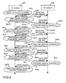
- Fig. 6 shows a message sequence chart for the feeding port selection process.
- the transmitting modem 600 selects in a step S602 the first (out of three) feeding possibilities and indicates this by a control message in a step S604 to the receiving modem 606.
- Such control messages might be handled in upper layers of any OSI layer system (e.g. a medium access layer (MAC) or even a data link control layer (DLC)).
- the receiving modem 606 acknowledges this request in a step S608 and waits for the start of the test transmission.
- the transmitting modem 600 starts the capacity test of the transmission possibility of the first feeding port 1 in a step S610 and sends a corresponding test signal in a step S612.
- the receiving modem 606 knows the length of a test transmission (e.g. a certain number of data bursts) it starts automatically to calculate the channel capacity as channel characteristic after the test sequence is received in a step S614. The result of the capacity calculation is sent back to the transmitter 600 in a step S616.
- a test transmission e.g. a certain number of data bursts
- a step S620 the transmitting modem 600 selects the second feeding possibility and indicates this by a control message in a step S622 to the receiving modem 606.
- the receiving modem 606 acknowledges this request in a step S624 and waits for the start of the next test transmission.
- the transmitting modem 600 starts the capacity test of the second feeding port FP2 in a step S626 and sends a corresponding test signal in a step S628.
- the receiving modem 606 calculates the channel capacity for this second feeding possibility in a step S630 and reports the capacity back to the transmitting modem 600 in a step S632.
- a step S634 the transmitting modem 600 selects the third feeding possibility and indicates this by a control message in a step S636 to the receiving modem 606.
- the receiving modem 606 acknowledges this request in a step S638 and waits for the start of the next test transmission.
- the transmitting modem 600 starts the capacity test of the third feeding port FP3 in a step S640 and sends a corresponding test signal in a step S642.
- the receiving modem 606 calculates the channel capacity for this second feeding possibility in a step S644 and reports the capacity back to the transmitting modem 600 in a step S646.
- the transmitting modem 606 starts to send regular data bursts in a step S650.
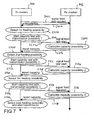
- Fig. 7 an alternative scheme for testing the channels is depicted.
- a receiving modem 706 knows the length of the test transmission from the transmitting modem 700, the handshaking to signal the start of the test sequence can be omitted.
- the transmitting modem 700 signals to the receiving modem 706 that a signal feed test is requested.
- the receiver 706 acknowledge the feed test request to the transmitter 700.
- the transmitter 700 selects the first feeding possibility and starts the capacity test directly for the first feeding port FP1 in a step S710.
- the test signal is transmitted in a step 712 and the receiving modem 706 calculates the capacity in a step S714.
- the channel capacity is reported back to the transmitter 700 in a step S716.
- a step S720 the transmitting modem 700 selects the second feeding possibility and starts the capacity test directly for the second feeding port FP2 in a step S722.
- the test signal is transmitted in a step 724 and the receiving modem 706 calculates the capacity in a step S726.
- the channel capacity is reported back to the transmitting modem 700 in a step S728.
- a step S730 the transmitting modem 700 selects the first feeding possibility and starts the capacity test directly for the third feeding port FP3 in a step S732.
- the test signal is transmitted in a step S734 and the receiving modem 706 calculates the capacity in a step S736.
- the channel capacity is reported back to the transmitting modem 700 in a step S738.
- the transmitting modem 700 selects the best feeding possibilities and starts the transmission in a step S740.
- Fig. 8 the block diagram of the transmitting PLC modem 800 is depicted in order to explain how to switch between the different feeding ports in the transmitter 800.
- two of the available three ports are selected from the two MIMO transmitting paths 802, 804 with the help of a switching mechanism 806.
- MIMO transmitting path 802 and MIMO transmitting path 2 804 are never set to the same position within the switching mechanism 806.
- the first transmitting path 802 is using P-N as feeding port and the second transmitting path is using P-PE as feeding port.
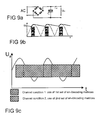
- Fig. 9A shows a circuit diagram and Fig. 9B shows a corresponding time dependence of the voltage UA on a power line, if impedance modulating devices are present.
- Mobile phone chargers and other charging devices convey in the circuitry that has the following properties:
- the periodic impedance changes have dramatic influence to data transmission over power line.
- An impedance change during a data burst results in wrong channel equalization values after the impedance change and causes non-correctable transmission errors. Therefore it is important to place the burst in time intervals where the impedance keeps stable, which is a task for a medium access control (MAC) layer of a power line communication system.
- MAC medium access control
- Fig. 9C it is depicted that depending on the line cycle frequency, different channel conditions result in different feeding port selections and/or different MIMO schemes (in this example: two different channel conditions, but all different channel conditions might be possible as well).
- the Y-axis represents the voltage UA of an AC line cycle.
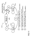
- Fig. 10 steps for determining an appropriate MIMO coding scheme is depicted.
- the channel characteristics are determined in a step S1002.
- a step S1004 it is investigated whether the signal-to-noise-ratio SNR is below a certain threshold. If the answer is yes in a step S1006 a stable, bit error rate (BER) - optimized MIMO coding is selected, for example, an Alamouti MIMO scheme. If the signal-to-noise-ratio is above a certain threshold it is determined whether significant disturbances are present in the power line network in a step S1008.
- BER bit error rate
- a stable, bit error rate optimized MIMO coding like Alamouti MIMO is used for the transmission as well. If there are no disturbances in the power line network then in a step S1010 a throughput optimized MIMO coding, like HBLAST, VBLAST or Eigenbeamforming-MIMO is selected. Afterwards in a step S1012 the transmitter is informed about the selection which selection should be used afterwards in a regular operation in a step S1014. Thus, depending on the channel characteristics, and/or the bandwidth demand of the application, an appropriate MIMO coding is selected.
- an initial phase before regular operation is proposed.
- the power line communication channel is examined for disturbances (impedance modulating or impulsive noise). All available MIMO schemes are tested sequentially. The best MIMO mode regarding throughput and/or bit error rate might be chosen.
- a further embodiment for a power line communication system 1100 is depicted.
- a first node 1102 is connected via a first channel 1104 with a second node 1106 and via a second channel 1108 with a third node 1110.
- the second node 1106 and the third node 1110 are connected via a third channel 1112.
- an impulsive noise source 1114 disturbs the third channel 1112 between the second node 1106 and the third node 1110.
- the selection of the MIMO mode might be performed for each connection between all nodes, 1102, 1106, 1110 in the network 1100, different connections between different nodes might choose different MIMO modes depending on the connection conditions.
- the communication between the first node 1102 and the second node 1106 on the first channel 1104 with a short distance has a good signal-to-noise-ratio SNR without any disturbance.
- a throughput optimized MIMO can be chosen.
- bit error rate optimized MIMO e.g. Alamouti
- a bit error rate optimized MIMO might be selected in order to overcome a bad SNR due to the long distance.
- the process to determine the optimized MIMO mode might be performed when a new node enters the network (and again if the channel conditions change fundamentally). It is proposed how to select the best possible feeding ports for MIMO communication over power line communication channels. The channel characteristics for different feeding ports are measured for all transmission possibilities and the port with the worst channel characteristics is excluded from further communication. In addition it has been prevented how to deal with impedance modulating devices in order to choose the appropriate feeding ports for different parts of an alternating current.
Priority Applications (14)
| Application Number | Priority Date | Filing Date | Title |
|---|---|---|---|
| EP16161629.7A EP3065303B1 (fr) | 2007-08-22 | 2007-08-22 | Procédé pour la transmission d'un signal via un réseau électrique, transmetteur, récepteur, modem de communications de réseau électrique et système de communications de réseau électrique |
| EP07016489.2A EP2028769B1 (fr) | 2007-08-22 | 2007-08-22 | Procédé pour la transmission d'un signal via un réseau électrique, transmetteur et récepteur, modem de communications de réseau électrique et système de communications de réseau électrique |
| EP11007114.9A EP2393214B1 (fr) | 2007-08-22 | 2007-08-22 | Procédé pour la transmission d'un signal via un réseau électrique, transmetteur et récepteur, modem de communications de réseau électrique et système de communications de réseau électrique |
| CN2008801047830A CN101785203B (zh) | 2007-08-22 | 2008-07-28 | 经由电力线网络传送信号的方法、传送器、接收器、电力线通信调制解调器和电力线通信系统 |
| RU2010105044/07A RU2481703C2 (ru) | 2007-08-22 | 2008-07-28 | Способ передачи сигнала через сеть линии электропередач, передатчик, приемник, модем передачи данных через линию электропередач и система передачи данных через линию электропередач |
| CN201310461916.2A CN103532593B (zh) | 2007-08-22 | 2008-07-28 | 电力线通信传送器和传送信号的方法 |
| US12/595,265 US8160162B2 (en) | 2007-08-22 | 2008-07-28 | Method for transmitting a signal via a power line network, transmitter, receiver, power line communication modem and power line communication system |
| BRPI0809648A BRPI0809648B1 (pt) | 2007-08-22 | 2008-07-28 | método para transmitir sinais através de uma rede de linha de potência, transmissor para transmitir sinais através de uma rede de linha de potência, receptor para receber sinais de um transmissor através de uma rede de linha de potência, modem de comunicação por linha de potência, e, sistema de comunicação por linha de potência |
| PCT/EP2008/006212 WO2009024249A1 (fr) | 2007-08-22 | 2008-07-28 | Procédé pour transmettre un signal par l'intermédiaire d'un réseau sur courant porteur, émetteur, récepteur, modem de communication par courant porteur et système de communication par courant porteur |
| KR1020097023528A KR101532449B1 (ko) | 2007-08-22 | 2008-07-28 | 전력선 네트워크를 통한 신호 전송 방법, 송신기, 수신기, 전력선 통신 모뎀, 및 전력선 통신 시스템 |
| US13/412,279 US8442127B2 (en) | 2007-08-22 | 2012-03-05 | Method for transmitting a signal via a power line network, transmitter, receiver, power line communication modem and power line communication system |
| US13/601,772 US8743975B2 (en) | 2007-08-22 | 2012-08-31 | Method for transmitting a signal via a power line network, transmitter, receiver, power line communication modem and power line communication system |
| US14/292,023 US9191068B2 (en) | 2007-08-22 | 2014-05-30 | Method for transmitting a signal via a power line network, transmitter, receiver, power line communication modem and power line communication system |
| US14/880,687 US9843357B2 (en) | 2007-08-22 | 2015-10-12 | Method for transmitting a signal via a power line network, transmitter, receiver, power line communication modem and power line communication system |
Applications Claiming Priority (1)
| Application Number | Priority Date | Filing Date | Title |
|---|---|---|---|
| EP07016489.2A EP2028769B1 (fr) | 2007-08-22 | 2007-08-22 | Procédé pour la transmission d'un signal via un réseau électrique, transmetteur et récepteur, modem de communications de réseau électrique et système de communications de réseau électrique |
Related Child Applications (4)
| Application Number | Title | Priority Date | Filing Date |
|---|---|---|---|
| EP16161629.7A Division EP3065303B1 (fr) | 2007-08-22 | 2007-08-22 | Procédé pour la transmission d'un signal via un réseau électrique, transmetteur, récepteur, modem de communications de réseau électrique et système de communications de réseau électrique |
| EP16161629.7A Division-Into EP3065303B1 (fr) | 2007-08-22 | 2007-08-22 | Procédé pour la transmission d'un signal via un réseau électrique, transmetteur, récepteur, modem de communications de réseau électrique et système de communications de réseau électrique |
| EP11007114.9A Division EP2393214B1 (fr) | 2007-08-22 | 2007-08-22 | Procédé pour la transmission d'un signal via un réseau électrique, transmetteur et récepteur, modem de communications de réseau électrique et système de communications de réseau électrique |
| EP11007114.9A Division-Into EP2393214B1 (fr) | 2007-08-22 | 2007-08-22 | Procédé pour la transmission d'un signal via un réseau électrique, transmetteur et récepteur, modem de communications de réseau électrique et système de communications de réseau électrique |
Publications (2)
| Publication Number | Publication Date |
|---|---|
| EP2028769A1 true EP2028769A1 (fr) | 2009-02-25 |
| EP2028769B1 EP2028769B1 (fr) | 2016-05-04 |
Family
ID=38924774
Family Applications (3)
| Application Number | Title | Priority Date | Filing Date |
|---|---|---|---|
| EP11007114.9A Active EP2393214B1 (fr) | 2007-08-22 | 2007-08-22 | Procédé pour la transmission d'un signal via un réseau électrique, transmetteur et récepteur, modem de communications de réseau électrique et système de communications de réseau électrique |
| EP07016489.2A Active EP2028769B1 (fr) | 2007-08-22 | 2007-08-22 | Procédé pour la transmission d'un signal via un réseau électrique, transmetteur et récepteur, modem de communications de réseau électrique et système de communications de réseau électrique |
| EP16161629.7A Active EP3065303B1 (fr) | 2007-08-22 | 2007-08-22 | Procédé pour la transmission d'un signal via un réseau électrique, transmetteur, récepteur, modem de communications de réseau électrique et système de communications de réseau électrique |
Family Applications Before (1)
| Application Number | Title | Priority Date | Filing Date |
|---|---|---|---|
| EP11007114.9A Active EP2393214B1 (fr) | 2007-08-22 | 2007-08-22 | Procédé pour la transmission d'un signal via un réseau électrique, transmetteur et récepteur, modem de communications de réseau électrique et système de communications de réseau électrique |
Family Applications After (1)
| Application Number | Title | Priority Date | Filing Date |
|---|---|---|---|
| EP16161629.7A Active EP3065303B1 (fr) | 2007-08-22 | 2007-08-22 | Procédé pour la transmission d'un signal via un réseau électrique, transmetteur, récepteur, modem de communications de réseau électrique et système de communications de réseau électrique |
Country Status (7)
| Country | Link |
|---|---|
| US (5) | US8160162B2 (fr) |
| EP (3) | EP2393214B1 (fr) |
| KR (1) | KR101532449B1 (fr) |
| CN (2) | CN103532593B (fr) |
| BR (1) | BRPI0809648B1 (fr) |
| RU (1) | RU2481703C2 (fr) |
| WO (1) | WO2009024249A1 (fr) |
Cited By (12)
| Publication number | Priority date | Publication date | Assignee | Title |
|---|---|---|---|---|
| WO2011001430A3 (fr) * | 2009-06-29 | 2011-04-07 | Coppergate Communication Ltd. | Procede et appareil de communication avec une ligne d'alimentation electrique |
| WO2011083238A1 (fr) * | 2009-12-22 | 2011-07-14 | France Telecom | Procede de selection d'un mode de transmission |
| US20120183085A1 (en) * | 2010-12-14 | 2012-07-19 | Broadcom Corporation | Module for powerline communication transmission |
| US8571124B2 (en) | 2007-05-02 | 2013-10-29 | Sigma Designs Israel S.D.I. Ltd. | Multiple input, multiple output (MIMO) communication system over in-premises wires |
| WO2014182734A1 (fr) * | 2013-05-06 | 2014-11-13 | Qualcomm Incorporated | Diversite de selection dans un systeme de communication par courants porteurs en ligne (plc) |
| US8902957B2 (en) | 2011-05-16 | 2014-12-02 | Sony Corporation | Power line communication modem, power line communication system, power line communication method |
| WO2015088717A1 (fr) * | 2013-12-12 | 2015-06-18 | Qualcomm Incorporated | Réutilisation de canal de réseau voisin par des stations à capacité mimo |
| US9143198B2 (en) | 2009-06-29 | 2015-09-22 | Sigma Designs Israel S.D.I. Ltd. | Power line communication method and apparatus |
| US9479221B2 (en) | 2009-06-29 | 2016-10-25 | Sigma Designs Israel S.D.I. Ltd. | Power line communication method and apparatus |
| EP2428860A3 (fr) * | 2010-09-13 | 2017-07-12 | Honeywell International Inc. | Dispositifs, procédés et systèmes pour la surveillance de bâtiments |
| EP3958470A1 (fr) * | 2020-08-19 | 2022-02-23 | Siemens Aktiengesellschaft | Procédé de transfert de données dans un réseau basse tension |
| EP4346052A1 (fr) * | 2022-09-30 | 2024-04-03 | GE Aviation Systems LLC | Système et procédé de fonctionnement d'un système de distribution d'énergie |
Families Citing this family (32)
| Publication number | Priority date | Publication date | Assignee | Title |
|---|---|---|---|---|
| US8638216B2 (en) * | 2004-09-17 | 2014-01-28 | Keith Lamon | Systems and methods for direct current system digital carried message conveyance |
| EP2393214B1 (fr) | 2007-08-22 | 2020-06-17 | Sony Corporation | Procédé pour la transmission d'un signal via un réseau électrique, transmetteur et récepteur, modem de communications de réseau électrique et système de communications de réseau électrique |
| EP2154789B1 (fr) * | 2008-08-11 | 2019-10-02 | Sony Corporation | Procédé pour détecter une entrée de signal radio à ondes courtes dans un système de communication par ligne électrique et modem de communication électrique |
| ATE543266T1 (de) | 2008-08-20 | 2012-02-15 | Sony Corp | Vorrichtung zum bestimmen eines gleichtaktsignals in einem stromleitungs-kommunikationsnetz |
| JP2011091791A (ja) * | 2009-09-24 | 2011-05-06 | Toyota Central R&D Labs Inc | 移動体用電力線通信方法 |
| KR101711235B1 (ko) | 2009-10-26 | 2017-02-28 | 소니 주식회사 | 전력선 통신 시스템에서 사용을 위한 장치 및 전력선 통신 시스템 |
| US8681619B2 (en) * | 2010-04-08 | 2014-03-25 | Landis+Gyr Technologies, Llc | Dynamic modulation selection |
| TWI521902B (zh) * | 2010-06-09 | 2016-02-11 | 新力股份有限公司 | 操作電力線通信(plc)系統之方法,plc數據機裝置,及plc系統 |
| IL214213A0 (en) * | 2010-07-20 | 2011-08-31 | Coppergate Comm Ltd | Transmission scheme for multiple-input communication |
| US8520696B1 (en) | 2010-07-30 | 2013-08-27 | Qualcomm Incorporated | Terminal selection diversity for powerline communications |
| WO2012142586A1 (fr) | 2011-04-15 | 2012-10-18 | Power Tagging Technologies, Inc. | Système et procédé permettant une optimisation unique et multizones de la prestation et de l'utilisation de services utilitaires |
| US9059842B2 (en) | 2011-06-09 | 2015-06-16 | Astrolink International Llc | System and method for grid based cyber security |
| US8483291B2 (en) * | 2011-06-30 | 2013-07-09 | Broadcom Corporation | Analog to digital converter with increased sub-range resolution |
| CN102832972B (zh) | 2012-09-05 | 2015-04-29 | 国网重庆市电力公司电力科学研究院 | 一种电力线通信系统及方法 |
| EP2907242B1 (fr) * | 2012-10-11 | 2018-08-22 | Sony Corporation | Dispositif pour communication par ligne électrique, procédé de transmission de signaux et procédé de réception de signaux |
| CN103138805B (zh) * | 2013-02-01 | 2015-02-18 | 北京曼若科技有限公司 | 电力线载波的传输方法、装置以及系统 |
| US10097240B2 (en) | 2013-02-19 | 2018-10-09 | Astrolink International, Llc | System and method for inferring schematic and topological properties of an electrical distribution grid |
| US9490887B2 (en) | 2013-03-28 | 2016-11-08 | Sony Corporation | Communication device and method providing beamforming for two or more transmission channels |
| MX357831B (es) | 2013-06-13 | 2018-07-26 | Astrolink Int Llc | Perdidas no tecnicas en una rejilla electrica publica. |
| US10749571B2 (en) | 2013-06-13 | 2020-08-18 | Trc Companies, Inc. | System and methods for inferring the feeder and phase powering an on-grid transmitter |
| CN104253630B (zh) * | 2013-06-26 | 2016-08-10 | 国际商业机器公司 | 利用电力线载波在电力线上传输数据的方法和系统 |
| KR101596144B1 (ko) * | 2014-06-18 | 2016-02-29 | 가톨릭대학교 산학협력단 | Mimo-ofdm 전력선 통신 방법 및 그 장치 |
| US10348418B1 (en) | 2014-07-22 | 2019-07-09 | Esker Technologies, LLC | Transient and spurious signal filter |
| US9258829B1 (en) * | 2014-09-30 | 2016-02-09 | Texas Instruments Incorporated | System and method for collision rate reduction in MIMO narrowband power line communications |
| PE20171123A1 (es) | 2014-10-30 | 2017-08-08 | Astrolink Int Llc | Sistema y metodos para asignar intervalos y resolver conflictos de intervalos en una red de distribucion electrica |
| US9559752B1 (en) | 2015-09-24 | 2017-01-31 | Qualcomm Incorporated | Switching signal polarity of a network device plug for use in a powerline communication network |
| US10417143B2 (en) | 2015-10-08 | 2019-09-17 | Esker Technologies, LLC | Apparatus and method for sending power over synchronous serial communication wiring |
| US10128906B2 (en) | 2016-07-11 | 2018-11-13 | Esker Technologies, LLC | Power line signal coupler |
| US10560154B2 (en) | 2016-07-11 | 2020-02-11 | Esker Technologies, LLC | Power line signal coupler |
| WO2019134911A1 (fr) | 2018-01-08 | 2019-07-11 | British Telecommunications Public Limited Company | Procédé et appareil de transmission de données dans un système de communication |
| CN110278008B (zh) * | 2018-03-16 | 2021-05-04 | 华为技术有限公司 | 一种电力线通信方法、装置及计算机存储介质 |
| WO2023224503A1 (fr) * | 2022-05-16 | 2023-11-23 | Qatar Foundation For Education, Science And Community Development | Surveillance de réseau électrique par l'intermédiaire d'un système de détection de topologie à l'aide de communications par courants porteurs en ligne |
Citations (5)
| Publication number | Priority date | Publication date | Assignee | Title |
|---|---|---|---|---|
| GB2383724A (en) * | 2001-12-15 | 2003-07-02 | Univ Lancaster | Space time coded data transmission via inductive effect between adjacent power lines |
| EP1643658A1 (fr) | 2004-10-04 | 2006-04-05 | Sony Deutschland GmbH | Procede de communications par courant porteur |
| US20060093058A1 (en) | 2004-10-27 | 2006-05-04 | Kabushiki Kaisha Toshiba | Multiple list link adaptation |
| US20060226958A1 (en) | 2005-03-16 | 2006-10-12 | Domosys Corporation | System and method for power line communication |
| EP1892843A1 (fr) | 2006-08-24 | 2008-02-27 | Sony Deutschland GmbH | Procédé de communication par courant porteur, transmetteur, récepteur et système. |
Family Cites Families (15)
| Publication number | Priority date | Publication date | Assignee | Title |
|---|---|---|---|---|
| US4060735A (en) * | 1976-07-12 | 1977-11-29 | Johnson Controls, Inc. | Control system employing a programmable multiple channel controller for transmitting control signals over electrical power lines |
| DE4328523A1 (de) | 1993-08-25 | 1995-03-02 | Telefunken Microelectron | Vorrichtung zur Datenübertragung auf elektrischen Niederspannungsnetzen |
| US5712614A (en) * | 1995-05-09 | 1998-01-27 | Elcom Technologies Corporation | Power line communications system |
| US5730165A (en) | 1995-12-26 | 1998-03-24 | Philipp; Harald | Time domain capacitive field detector |
| DE19716011A1 (de) * | 1997-04-17 | 1998-10-22 | Abb Research Ltd | Verfahren und Vorrichtung zur Informationsübertragung über Stromversorgungsleitungen |
| US6249213B1 (en) * | 1998-12-17 | 2001-06-19 | Intel Corporation | Method for transmitting information over an alternating current power line through a plurality of frequency orthogonal subchannels |
| US20020027985A1 (en) * | 2000-06-12 | 2002-03-07 | Farrokh Rashid-Farrokhi | Parallel processing for multiple-input, multiple-output, DSL systems |
| RU2209513C2 (ru) * | 2000-08-02 | 2003-07-27 | Открытое акционерное общество энергетики и электрификации "Волгоградэнерго" | Система передачи сигналов по линии электроснабжения для обнаружения гололедных отложений на проводах |
| US7010050B2 (en) * | 2001-08-30 | 2006-03-07 | Yamar Electronics Ltd. | Signaling over noisy channels |
| US7106177B2 (en) * | 2002-08-21 | 2006-09-12 | Arkados, Inc. | Method and system for modifying modulation of power line communications signals for maximizing data throughput rate |
| US20040218530A1 (en) * | 2003-04-30 | 2004-11-04 | Spediant Systems Ltd. | Maximization of data transmission via multiple links in the presence of crosstalk |
| JP4970954B2 (ja) * | 2003-12-23 | 2012-07-11 | エスティーマイクロエレクトロニクス,インコーポレイテッド | 通信プロトコル物理層の動作がダイナミックに選択可能である電力線通信装置 |
| JP2006101487A (ja) * | 2004-09-02 | 2006-04-13 | Mitsubishi Materials Corp | データ通信システム、データ送信装置、データ受信装置及びデータ通信方法並びにデータ通信プログラム |
| US7852207B2 (en) * | 2006-02-14 | 2010-12-14 | Current Technologies, Llc | Method for establishing power line communication link |
| EP2393214B1 (fr) * | 2007-08-22 | 2020-06-17 | Sony Corporation | Procédé pour la transmission d'un signal via un réseau électrique, transmetteur et récepteur, modem de communications de réseau électrique et système de communications de réseau électrique |
-
2007
- 2007-08-22 EP EP11007114.9A patent/EP2393214B1/fr active Active
- 2007-08-22 EP EP07016489.2A patent/EP2028769B1/fr active Active
- 2007-08-22 EP EP16161629.7A patent/EP3065303B1/fr active Active
-
2008
- 2008-07-28 US US12/595,265 patent/US8160162B2/en active Active
- 2008-07-28 KR KR1020097023528A patent/KR101532449B1/ko active IP Right Grant
- 2008-07-28 RU RU2010105044/07A patent/RU2481703C2/ru active
- 2008-07-28 CN CN201310461916.2A patent/CN103532593B/zh active Active
- 2008-07-28 WO PCT/EP2008/006212 patent/WO2009024249A1/fr active Application Filing
- 2008-07-28 BR BRPI0809648A patent/BRPI0809648B1/pt not_active IP Right Cessation
- 2008-07-28 CN CN2008801047830A patent/CN101785203B/zh not_active Expired - Fee Related
-
2012
- 2012-03-05 US US13/412,279 patent/US8442127B2/en active Active
- 2012-08-31 US US13/601,772 patent/US8743975B2/en active Active
-
2014
- 2014-05-30 US US14/292,023 patent/US9191068B2/en active Active
-
2015
- 2015-10-12 US US14/880,687 patent/US9843357B2/en active Active
Patent Citations (5)
| Publication number | Priority date | Publication date | Assignee | Title |
|---|---|---|---|---|
| GB2383724A (en) * | 2001-12-15 | 2003-07-02 | Univ Lancaster | Space time coded data transmission via inductive effect between adjacent power lines |
| EP1643658A1 (fr) | 2004-10-04 | 2006-04-05 | Sony Deutschland GmbH | Procede de communications par courant porteur |
| US20060093058A1 (en) | 2004-10-27 | 2006-05-04 | Kabushiki Kaisha Toshiba | Multiple list link adaptation |
| US20060226958A1 (en) | 2005-03-16 | 2006-10-12 | Domosys Corporation | System and method for power line communication |
| EP1892843A1 (fr) | 2006-08-24 | 2008-02-27 | Sony Deutschland GmbH | Procédé de communication par courant porteur, transmetteur, récepteur et système. |
Cited By (25)
| Publication number | Priority date | Publication date | Assignee | Title |
|---|---|---|---|---|
| US8571124B2 (en) | 2007-05-02 | 2013-10-29 | Sigma Designs Israel S.D.I. Ltd. | Multiple input, multiple output (MIMO) communication system over in-premises wires |
| EP2143244A4 (fr) * | 2007-05-02 | 2014-07-16 | Sigma Designs Israel Sdi Ltd | Système de communication entrée multiple sortie multiple (mimo) sur des câbles de locaux |
| US8952567B2 (en) | 2009-06-29 | 2015-02-10 | Sigma Designs Israel S.D.I. Ltd. | Power line communications method and apparatus |
| US9191067B2 (en) | 2009-06-29 | 2015-11-17 | Sigma Designs Israel S.D.I. Ltd. | Power line communications method and apparatus |
| WO2011001430A3 (fr) * | 2009-06-29 | 2011-04-07 | Coppergate Communication Ltd. | Procede et appareil de communication avec une ligne d'alimentation electrique |
| EP2453583A2 (fr) * | 2009-06-29 | 2012-05-16 | Sigma Designs Israel S.D.I Ltd. | Procédé et appareil de communications par courant porteur |
| US9479221B2 (en) | 2009-06-29 | 2016-10-25 | Sigma Designs Israel S.D.I. Ltd. | Power line communication method and apparatus |
| EP2453584A1 (fr) | 2009-06-29 | 2012-05-16 | Sigma Designs Israel S.D.I Ltd. | Procédé et appareil de communication de ligne d'alimentation |
| US8879644B2 (en) | 2009-06-29 | 2014-11-04 | Sigma Designs Israel S.D.I. Ltd. | Power line communications method and apparatus |
| US9143198B2 (en) | 2009-06-29 | 2015-09-22 | Sigma Designs Israel S.D.I. Ltd. | Power line communication method and apparatus |
| EP2453583A3 (fr) * | 2009-06-29 | 2014-12-17 | Sigma Designs Israel S.D.I Ltd. | Procédé et appareil de communications par courant porteur |
| WO2011083238A1 (fr) * | 2009-12-22 | 2011-07-14 | France Telecom | Procede de selection d'un mode de transmission |
| US8867637B2 (en) | 2009-12-22 | 2014-10-21 | France Telecom | Method for selecting a transmission mode |
| EP2428860A3 (fr) * | 2010-09-13 | 2017-07-12 | Honeywell International Inc. | Dispositifs, procédés et systèmes pour la surveillance de bâtiments |
| US9035484B2 (en) * | 2010-12-14 | 2015-05-19 | Broadcom Corporation | Module for powerline communication transmission |
| US20120183085A1 (en) * | 2010-12-14 | 2012-07-19 | Broadcom Corporation | Module for powerline communication transmission |
| US8902957B2 (en) | 2011-05-16 | 2014-12-02 | Sony Corporation | Power line communication modem, power line communication system, power line communication method |
| US9667320B2 (en) | 2011-05-16 | 2017-05-30 | Sony Corporation | Power line communication modem, power line communication system, power line communication method |
| US9130658B2 (en) | 2013-05-06 | 2015-09-08 | Qualcomm Incorporated | Selection diversity in a powerline communication system |
| WO2014182734A1 (fr) * | 2013-05-06 | 2014-11-13 | Qualcomm Incorporated | Diversite de selection dans un systeme de communication par courants porteurs en ligne (plc) |
| JP2016521525A (ja) * | 2013-05-06 | 2016-07-21 | クゥアルコム・インコーポレイテッドQualcomm Incorporated | 電力線通信システムにおける選択ダイバーシティ |
| WO2015088717A1 (fr) * | 2013-12-12 | 2015-06-18 | Qualcomm Incorporated | Réutilisation de canal de réseau voisin par des stations à capacité mimo |
| US9137004B2 (en) | 2013-12-12 | 2015-09-15 | Qualcomm Incorporated | Neighbor network channel reuse with MIMO capable stations |
| EP3958470A1 (fr) * | 2020-08-19 | 2022-02-23 | Siemens Aktiengesellschaft | Procédé de transfert de données dans un réseau basse tension |
| EP4346052A1 (fr) * | 2022-09-30 | 2024-04-03 | GE Aviation Systems LLC | Système et procédé de fonctionnement d'un système de distribution d'énergie |
Also Published As
| Publication number | Publication date |
|---|---|
| US8160162B2 (en) | 2012-04-17 |
| US20100061433A1 (en) | 2010-03-11 |
| US20160105217A1 (en) | 2016-04-14 |
| RU2481703C2 (ru) | 2013-05-10 |
| US20140348251A1 (en) | 2014-11-27 |
| BRPI0809648A2 (pt) | 2014-09-23 |
| CN103532593B (zh) | 2016-06-01 |
| CN101785203A (zh) | 2010-07-21 |
| US9191068B2 (en) | 2015-11-17 |
| US8442127B2 (en) | 2013-05-14 |
| US20120163436A1 (en) | 2012-06-28 |
| EP2393214B1 (fr) | 2020-06-17 |
| US20120328030A1 (en) | 2012-12-27 |
| EP3065303A1 (fr) | 2016-09-07 |
| KR20100042244A (ko) | 2010-04-23 |
| KR101532449B1 (ko) | 2015-07-06 |
| WO2009024249A1 (fr) | 2009-02-26 |
| EP2028769B1 (fr) | 2016-05-04 |
| CN101785203B (zh) | 2013-10-30 |
| EP2393214A1 (fr) | 2011-12-07 |
| RU2010105044A (ru) | 2011-08-20 |
| US9843357B2 (en) | 2017-12-12 |
| US8743975B2 (en) | 2014-06-03 |
| CN103532593A (zh) | 2014-01-22 |
| EP3065303B1 (fr) | 2019-01-02 |
| BRPI0809648B1 (pt) | 2019-10-22 |
Similar Documents
| Publication | Publication Date | Title |
|---|---|---|
| EP2393214B1 (fr) | Procédé pour la transmission d'un signal via un réseau électrique, transmetteur et récepteur, modem de communications de réseau électrique et système de communications de réseau électrique | |
| CN102687436B (zh) | 利用波束形成的通信系统 | |
| EP2312764B1 (fr) | Appareil de communication par ligne de transport d'énergie et procédé de communication par ligne de transport d'énergie | |
| EP2504944B1 (fr) | DSL à l'aide d'un cable à plusieurs fils | |
| US8368351B2 (en) | Transmission line directional awareness for a charging station | |
| US9143198B2 (en) | Power line communication method and apparatus | |
| WO2009126811A2 (fr) | Sensibilité directionnelle de ligne de transmission | |
| US9479221B2 (en) | Power line communication method and apparatus | |
| CA3006030A1 (fr) | Recuperation de donnees de symboles de donnees | |
| US8995593B2 (en) | Communication device using spatial diversity, communications system and method | |
| EP3076603A1 (fr) | Appareil de réduction de brouillage et procédé de réduction de brouillage pour une ligne de transmission de réseau domestique, et système de communication les utilisant | |
| WO2010151570A1 (fr) | Sensibilite directionnelle de ligne de transmission |
Legal Events
| Date | Code | Title | Description |
|---|---|---|---|
| PUAI | Public reference made under article 153(3) epc to a published international application that has entered the european phase |
Free format text: ORIGINAL CODE: 0009012 |
|
| AK | Designated contracting states |
Kind code of ref document: A1 Designated state(s): AT BE BG CH CY CZ DE DK EE ES FI FR GB GR HU IE IS IT LI LT LU LV MC MT NL PL PT RO SE SI SK TR |
|
| AX | Request for extension of the european patent |
Extension state: AL BA HR MK RS |
|
| 17Q | First examination report despatched |
Effective date: 20090921 |
|
| AKX | Designation fees paid |
Designated state(s): AT BE BG CH CY CZ DE DK EE ES FI FR GB GR HU IE IS IT LI LT LU LV MC MT NL PL PT RO SE SI SK TR |
|
| 17P | Request for examination filed |
Effective date: 20090824 |
|
| GRAP | Despatch of communication of intention to grant a patent |
Free format text: ORIGINAL CODE: EPIDOSNIGR1 |
|
| RIC1 | Information provided on ipc code assigned before grant |
Ipc: H04L 1/06 20060101ALI20151026BHEP Ipc: H04L 1/00 20060101ALI20151026BHEP Ipc: H04B 3/32 20060101ALI20151026BHEP Ipc: H04L 5/00 20060101ALI20151026BHEP Ipc: H04B 3/54 20060101AFI20151026BHEP |
|
| INTG | Intention to grant announced |
Effective date: 20151116 |
|
| GRAS | Grant fee paid |
Free format text: ORIGINAL CODE: EPIDOSNIGR3 |
|
| GRAA | (expected) grant |
Free format text: ORIGINAL CODE: 0009210 |
|
| AK | Designated contracting states |
Kind code of ref document: B1 Designated state(s): AT BE BG CH CY CZ DE DK EE ES FI FR GB GR HU IE IS IT LI LT LU LV MC MT NL PL PT RO SE SI SK TR |
|
| REG | Reference to a national code |
Ref country code: GB Ref legal event code: FG4D |
|
| REG | Reference to a national code |
Ref country code: CH Ref legal event code: EP |
|
| REG | Reference to a national code |
Ref country code: AT Ref legal event code: REF Ref document number: 797702 Country of ref document: AT Kind code of ref document: T Effective date: 20160515 |
|
| REG | Reference to a national code |
Ref country code: IE Ref legal event code: FG4D |
|
| REG | Reference to a national code |
Ref country code: DE Ref legal event code: R096 Ref document number: 602007046092 Country of ref document: DE |
|
| REG | Reference to a national code |
Ref country code: FR Ref legal event code: PLFP Year of fee payment: 10 |
|
| REG | Reference to a national code |
Ref country code: NL Ref legal event code: MP Effective date: 20160504 |
|
| REG | Reference to a national code |
Ref country code: LT Ref legal event code: MG4D |
|
| PG25 | Lapsed in a contracting state [announced via postgrant information from national office to epo] |
Ref country code: LT Free format text: LAPSE BECAUSE OF FAILURE TO SUBMIT A TRANSLATION OF THE DESCRIPTION OR TO PAY THE FEE WITHIN THE PRESCRIBED TIME-LIMIT Effective date: 20160504 Ref country code: NL Free format text: LAPSE BECAUSE OF FAILURE TO SUBMIT A TRANSLATION OF THE DESCRIPTION OR TO PAY THE FEE WITHIN THE PRESCRIBED TIME-LIMIT Effective date: 20160504 Ref country code: FI Free format text: LAPSE BECAUSE OF FAILURE TO SUBMIT A TRANSLATION OF THE DESCRIPTION OR TO PAY THE FEE WITHIN THE PRESCRIBED TIME-LIMIT Effective date: 20160504 |
|
| REG | Reference to a national code |
Ref country code: AT Ref legal event code: MK05 Ref document number: 797702 Country of ref document: AT Kind code of ref document: T Effective date: 20160504 |
|
| PG25 | Lapsed in a contracting state [announced via postgrant information from national office to epo] |
Ref country code: GR Free format text: LAPSE BECAUSE OF FAILURE TO SUBMIT A TRANSLATION OF THE DESCRIPTION OR TO PAY THE FEE WITHIN THE PRESCRIBED TIME-LIMIT Effective date: 20160805 Ref country code: ES Free format text: LAPSE BECAUSE OF FAILURE TO SUBMIT A TRANSLATION OF THE DESCRIPTION OR TO PAY THE FEE WITHIN THE PRESCRIBED TIME-LIMIT Effective date: 20160504 Ref country code: SE Free format text: LAPSE BECAUSE OF FAILURE TO SUBMIT A TRANSLATION OF THE DESCRIPTION OR TO PAY THE FEE WITHIN THE PRESCRIBED TIME-LIMIT Effective date: 20160504 Ref country code: PT Free format text: LAPSE BECAUSE OF FAILURE TO SUBMIT A TRANSLATION OF THE DESCRIPTION OR TO PAY THE FEE WITHIN THE PRESCRIBED TIME-LIMIT Effective date: 20160905 Ref country code: LV Free format text: LAPSE BECAUSE OF FAILURE TO SUBMIT A TRANSLATION OF THE DESCRIPTION OR TO PAY THE FEE WITHIN THE PRESCRIBED TIME-LIMIT Effective date: 20160504 |
|
| PG25 | Lapsed in a contracting state [announced via postgrant information from national office to epo] |
Ref country code: IT Free format text: LAPSE BECAUSE OF FAILURE TO SUBMIT A TRANSLATION OF THE DESCRIPTION OR TO PAY THE FEE WITHIN THE PRESCRIBED TIME-LIMIT Effective date: 20160504 Ref country code: BE Free format text: LAPSE BECAUSE OF NON-PAYMENT OF DUE FEES Effective date: 20160831 |
|
| PG25 | Lapsed in a contracting state [announced via postgrant information from national office to epo] |
Ref country code: RO Free format text: LAPSE BECAUSE OF FAILURE TO SUBMIT A TRANSLATION OF THE DESCRIPTION OR TO PAY THE FEE WITHIN THE PRESCRIBED TIME-LIMIT Effective date: 20160504 Ref country code: DK Free format text: LAPSE BECAUSE OF FAILURE TO SUBMIT A TRANSLATION OF THE DESCRIPTION OR TO PAY THE FEE WITHIN THE PRESCRIBED TIME-LIMIT Effective date: 20160504 Ref country code: EE Free format text: LAPSE BECAUSE OF FAILURE TO SUBMIT A TRANSLATION OF THE DESCRIPTION OR TO PAY THE FEE WITHIN THE PRESCRIBED TIME-LIMIT Effective date: 20160504 Ref country code: SK Free format text: LAPSE BECAUSE OF FAILURE TO SUBMIT A TRANSLATION OF THE DESCRIPTION OR TO PAY THE FEE WITHIN THE PRESCRIBED TIME-LIMIT Effective date: 20160504 Ref country code: CZ Free format text: LAPSE BECAUSE OF FAILURE TO SUBMIT A TRANSLATION OF THE DESCRIPTION OR TO PAY THE FEE WITHIN THE PRESCRIBED TIME-LIMIT Effective date: 20160504 |
|
| REG | Reference to a national code |
Ref country code: DE Ref legal event code: R097 Ref document number: 602007046092 Country of ref document: DE |
|
| PG25 | Lapsed in a contracting state [announced via postgrant information from national office to epo] |
Ref country code: PL Free format text: LAPSE BECAUSE OF FAILURE TO SUBMIT A TRANSLATION OF THE DESCRIPTION OR TO PAY THE FEE WITHIN THE PRESCRIBED TIME-LIMIT Effective date: 20160504 Ref country code: BE Free format text: LAPSE BECAUSE OF FAILURE TO SUBMIT A TRANSLATION OF THE DESCRIPTION OR TO PAY THE FEE WITHIN THE PRESCRIBED TIME-LIMIT Effective date: 20160504 Ref country code: AT Free format text: LAPSE BECAUSE OF FAILURE TO SUBMIT A TRANSLATION OF THE DESCRIPTION OR TO PAY THE FEE WITHIN THE PRESCRIBED TIME-LIMIT Effective date: 20160504 |
|
| PLBE | No opposition filed within time limit |
Free format text: ORIGINAL CODE: 0009261 |
|
| STAA | Information on the status of an ep patent application or granted ep patent |
Free format text: STATUS: NO OPPOSITION FILED WITHIN TIME LIMIT |
|
| PG25 | Lapsed in a contracting state [announced via postgrant information from national office to epo] |
Ref country code: MC Free format text: LAPSE BECAUSE OF FAILURE TO SUBMIT A TRANSLATION OF THE DESCRIPTION OR TO PAY THE FEE WITHIN THE PRESCRIBED TIME-LIMIT Effective date: 20160504 |
|
| REG | Reference to a national code |
Ref country code: CH Ref legal event code: PL |
|
| 26N | No opposition filed |
Effective date: 20170207 |
|
| PG25 | Lapsed in a contracting state [announced via postgrant information from national office to epo] |
Ref country code: LI Free format text: LAPSE BECAUSE OF NON-PAYMENT OF DUE FEES Effective date: 20160831 Ref country code: CH Free format text: LAPSE BECAUSE OF NON-PAYMENT OF DUE FEES Effective date: 20160831 |
|
| REG | Reference to a national code |
Ref country code: FR Ref legal event code: RU Effective date: 20170329 |
|
| PG25 | Lapsed in a contracting state [announced via postgrant information from national office to epo] |
Ref country code: SI Free format text: LAPSE BECAUSE OF FAILURE TO SUBMIT A TRANSLATION OF THE DESCRIPTION OR TO PAY THE FEE WITHIN THE PRESCRIBED TIME-LIMIT Effective date: 20160504 |
|
| REG | Reference to a national code |
Ref country code: IE Ref legal event code: MM4A |
|
| PG25 | Lapsed in a contracting state [announced via postgrant information from national office to epo] |
Ref country code: IE Free format text: LAPSE BECAUSE OF NON-PAYMENT OF DUE FEES Effective date: 20160822 |
|
| REG | Reference to a national code |
Ref country code: FR Ref legal event code: PLFP Year of fee payment: 11 |
|
| REG | Reference to a national code |
Ref country code: FR Ref legal event code: D7 Effective date: 20170724 |
|
| PG25 | Lapsed in a contracting state [announced via postgrant information from national office to epo] |
Ref country code: LU Free format text: LAPSE BECAUSE OF NON-PAYMENT OF DUE FEES Effective date: 20160822 |
|
| PG25 | Lapsed in a contracting state [announced via postgrant information from national office to epo] |
Ref country code: HU Free format text: LAPSE BECAUSE OF FAILURE TO SUBMIT A TRANSLATION OF THE DESCRIPTION OR TO PAY THE FEE WITHIN THE PRESCRIBED TIME-LIMIT; INVALID AB INITIO Effective date: 20070822 Ref country code: CY Free format text: LAPSE BECAUSE OF FAILURE TO SUBMIT A TRANSLATION OF THE DESCRIPTION OR TO PAY THE FEE WITHIN THE PRESCRIBED TIME-LIMIT Effective date: 20160504 |
|
| PG25 | Lapsed in a contracting state [announced via postgrant information from national office to epo] |
Ref country code: TR Free format text: LAPSE BECAUSE OF FAILURE TO SUBMIT A TRANSLATION OF THE DESCRIPTION OR TO PAY THE FEE WITHIN THE PRESCRIBED TIME-LIMIT Effective date: 20160504 Ref country code: IS Free format text: LAPSE BECAUSE OF FAILURE TO SUBMIT A TRANSLATION OF THE DESCRIPTION OR TO PAY THE FEE WITHIN THE PRESCRIBED TIME-LIMIT Effective date: 20160504 Ref country code: MT Free format text: LAPSE BECAUSE OF NON-PAYMENT OF DUE FEES Effective date: 20160831 |
|
| PG25 | Lapsed in a contracting state [announced via postgrant information from national office to epo] |
Ref country code: BG Free format text: LAPSE BECAUSE OF FAILURE TO SUBMIT A TRANSLATION OF THE DESCRIPTION OR TO PAY THE FEE WITHIN THE PRESCRIBED TIME-LIMIT Effective date: 20160504 |
|
| REG | Reference to a national code |
Ref country code: FR Ref legal event code: PLFP Year of fee payment: 12 |
|
| PGFP | Annual fee paid to national office [announced via postgrant information from national office to epo] |
Ref country code: GB Payment date: 20220721 Year of fee payment: 16 Ref country code: DE Payment date: 20220616 Year of fee payment: 16 |
|
| PGFP | Annual fee paid to national office [announced via postgrant information from national office to epo] |
Ref country code: FR Payment date: 20220721 Year of fee payment: 16 |
|
| P01 | Opt-out of the competence of the unified patent court (upc) registered |
Effective date: 20230527 |
|
| REG | Reference to a national code |
Ref country code: DE Ref legal event code: R119 Ref document number: 602007046092 Country of ref document: DE |