EP2028709A1 - Brennstoffzellensystem - Google Patents
Brennstoffzellensystem Download PDFInfo
- Publication number
- EP2028709A1 EP2028709A1 EP08162157A EP08162157A EP2028709A1 EP 2028709 A1 EP2028709 A1 EP 2028709A1 EP 08162157 A EP08162157 A EP 08162157A EP 08162157 A EP08162157 A EP 08162157A EP 2028709 A1 EP2028709 A1 EP 2028709A1
- Authority
- EP
- European Patent Office
- Prior art keywords
- gas
- fuel cell
- reformer
- interior
- cathode
- Prior art date
- Legal status (The legal status is an assumption and is not a legal conclusion. Google has not performed a legal analysis and makes no representation as to the accuracy of the status listed.)
- Granted
Links
Images

Classifications
-
- H—ELECTRICITY
- H01—ELECTRIC ELEMENTS
- H01M—PROCESSES OR MEANS, e.g. BATTERIES, FOR THE DIRECT CONVERSION OF CHEMICAL ENERGY INTO ELECTRICAL ENERGY
- H01M8/00—Fuel cells; Manufacture thereof
- H01M8/24—Grouping of fuel cells, e.g. stacking of fuel cells
- H01M8/2465—Details of groupings of fuel cells
- H01M8/247—Arrangements for tightening a stack, for accommodation of a stack in a tank or for assembling different tanks
-
- H—ELECTRICITY
- H01—ELECTRIC ELEMENTS
- H01M—PROCESSES OR MEANS, e.g. BATTERIES, FOR THE DIRECT CONVERSION OF CHEMICAL ENERGY INTO ELECTRICAL ENERGY
- H01M8/00—Fuel cells; Manufacture thereof
- H01M8/04—Auxiliary arrangements, e.g. for control of pressure or for circulation of fluids
- H01M8/04007—Auxiliary arrangements, e.g. for control of pressure or for circulation of fluids related to heat exchange
- H01M8/04014—Heat exchange using gaseous fluids; Heat exchange by combustion of reactants
-
- H—ELECTRICITY
- H01—ELECTRIC ELEMENTS
- H01M—PROCESSES OR MEANS, e.g. BATTERIES, FOR THE DIRECT CONVERSION OF CHEMICAL ENERGY INTO ELECTRICAL ENERGY
- H01M8/00—Fuel cells; Manufacture thereof
- H01M8/04—Auxiliary arrangements, e.g. for control of pressure or for circulation of fluids
- H01M8/04223—Auxiliary arrangements, e.g. for control of pressure or for circulation of fluids during start-up or shut-down; Depolarisation or activation, e.g. purging; Means for short-circuiting defective fuel cells
- H01M8/04268—Heating of fuel cells during the start-up of the fuel cells
-
- H—ELECTRICITY
- H01—ELECTRIC ELEMENTS
- H01M—PROCESSES OR MEANS, e.g. BATTERIES, FOR THE DIRECT CONVERSION OF CHEMICAL ENERGY INTO ELECTRICAL ENERGY
- H01M8/00—Fuel cells; Manufacture thereof
- H01M8/06—Combination of fuel cells with means for production of reactants or for treatment of residues
- H01M8/0606—Combination of fuel cells with means for production of reactants or for treatment of residues with means for production of gaseous reactants
- H01M8/0612—Combination of fuel cells with means for production of reactants or for treatment of residues with means for production of gaseous reactants from carbon-containing material
- H01M8/0625—Combination of fuel cells with means for production of reactants or for treatment of residues with means for production of gaseous reactants from carbon-containing material in a modular combined reactor/fuel cell structure
-
- H—ELECTRICITY
- H01—ELECTRIC ELEMENTS
- H01M—PROCESSES OR MEANS, e.g. BATTERIES, FOR THE DIRECT CONVERSION OF CHEMICAL ENERGY INTO ELECTRICAL ENERGY
- H01M8/00—Fuel cells; Manufacture thereof
- H01M8/24—Grouping of fuel cells, e.g. stacking of fuel cells
- H01M8/2465—Details of groupings of fuel cells
- H01M8/247—Arrangements for tightening a stack, for accommodation of a stack in a tank or for assembling different tanks
- H01M8/2475—Enclosures, casings or containers of fuel cell stacks
-
- H—ELECTRICITY
- H01—ELECTRIC ELEMENTS
- H01M—PROCESSES OR MEANS, e.g. BATTERIES, FOR THE DIRECT CONVERSION OF CHEMICAL ENERGY INTO ELECTRICAL ENERGY
- H01M2250/00—Fuel cells for particular applications; Specific features of fuel cell system
- H01M2250/20—Fuel cells in motive systems, e.g. vehicle, ship, plane
-
- Y—GENERAL TAGGING OF NEW TECHNOLOGICAL DEVELOPMENTS; GENERAL TAGGING OF CROSS-SECTIONAL TECHNOLOGIES SPANNING OVER SEVERAL SECTIONS OF THE IPC; TECHNICAL SUBJECTS COVERED BY FORMER USPC CROSS-REFERENCE ART COLLECTIONS [XRACs] AND DIGESTS
- Y02—TECHNOLOGIES OR APPLICATIONS FOR MITIGATION OR ADAPTATION AGAINST CLIMATE CHANGE
- Y02E—REDUCTION OF GREENHOUSE GAS [GHG] EMISSIONS, RELATED TO ENERGY GENERATION, TRANSMISSION OR DISTRIBUTION
- Y02E60/00—Enabling technologies; Technologies with a potential or indirect contribution to GHG emissions mitigation
- Y02E60/30—Hydrogen technology
- Y02E60/50—Fuel cells
-
- Y—GENERAL TAGGING OF NEW TECHNOLOGICAL DEVELOPMENTS; GENERAL TAGGING OF CROSS-SECTIONAL TECHNOLOGIES SPANNING OVER SEVERAL SECTIONS OF THE IPC; TECHNICAL SUBJECTS COVERED BY FORMER USPC CROSS-REFERENCE ART COLLECTIONS [XRACs] AND DIGESTS
- Y02—TECHNOLOGIES OR APPLICATIONS FOR MITIGATION OR ADAPTATION AGAINST CLIMATE CHANGE
- Y02T—CLIMATE CHANGE MITIGATION TECHNOLOGIES RELATED TO TRANSPORTATION
- Y02T90/00—Enabling technologies or technologies with a potential or indirect contribution to GHG emissions mitigation
- Y02T90/40—Application of hydrogen technology to transportation, e.g. using fuel cells
Definitions
- the present invention relates to a fuel cell system, in particular in a motor vehicle.
- a fuel cell system includes at least one fuel cell for generating electric power from hydrogen gas-containing anode gas and oxygen gas-containing cathode gas.
- a fuel cell system may include a reformer for generating hydrogen gas-containing anode gas of hydrogen-containing fuel and oxygen-containing oxidizer gas.
- a thermally insulating insulating sheath which encloses an interior in which at least the fuel cell is arranged.
- the reformer can also be arranged in this interior.
- a fuel cell system in which the fuel cell is arranged in an installation space, is sucked from the cathode gas to supply the fuel cell. This can cause the formation of a explosive mixture can be reduced in this installation space or in the respective environment of the fuel cell system. Such an explosive mixture can be caused by leaks, passes through the fuel gas in the environment of the fuel cell system or in the installation space.
- the present invention addresses the problem of providing a fuel cell system of the type mentioned an improved embodiment, which is characterized in particular by increased efficiency.
- the invention is based on the general idea to integrate the enclosed by the insulating sheath interior in the gas path for supplying the fuel cell with cathode gas or in the gas path for supplying the reformer with oxidizing gas and to design such that the cathode gas and the oxidant gas of the fuel cell and / withdrawing heat from the reformer before it enters the fuels or the reformer.
- a cooling of the fuel cell or of the reformer can be achieved
- a preheating of the cathode gas or of the oxidizer gas is achieved, which favors the fuel cell process or the reforming process.
- This preheating of the respective gas is particularly particular in a restart or warm start of the fuel cell system of particular Interest in bringing the system up to operating temperature as quickly as possible. This shortened warm start can increase the efficiency of the system.
- the fuel cell system may be equipped with a residual gas burner, in which a combustion of hydrogen gas-containing anode exhaust gas with oxygen gas containing cathode exhaust gas can be realized.
- a combustion of hydrogen gas-containing anode exhaust gas with oxygen gas containing cathode exhaust gas can be realized.
- the gas path in the interior of the insulation sheath can be deliberately guided so that at least the cathode gas and / or the oxidizer gas extracts heat from this residual gas burner before it reaches the fuel cell or the reformer.
- this design supports a restart or cold start of the fuel cell system, in which all components essentially have ambient temperature.
- the heat transfer from the residual gas burner or from the fuel cell or from the reformer to the respective gas can be realized, for example, by virtue of the fact that the cathode gas or the oxidizing gas flows against the respective component and / or flows around, whereby the heat transfer is promoted to the flowing gas.
- the gas path in the interior is controllable, in such a way that at least the cathode gas or the oxidizing gas during a cold start operation preferably or exclusively applied to the residual gas burner or a residual gas burner downstream heat exchanger and during a warm start operation or During normal operation, preferably or exclusively, the fuel cell or the reformer is applied to absorb heat.
- the fuel cell or the reformer is applied to absorb heat.
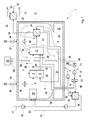
- Fig. 1 to 3 comprises a fuel cell system 1, which may preferably be arranged in a motor vehicle, at least one fuel cell 2 and a (first) Oxidatorboards worn 3.
- the fuel cell 2 is used in a conventional manner for generating electricity from a hydrogen gas-containing fuel gas and an oxygen gas-containing oxidant gas.
- the fuel gas is supplied to an anode side 4 of the fuel cell 2, while the oxidizer gas, which is expediently air, a cathode side 5 of the fuel cell 2 is supplied.
- an electrolyte 6 separates the anode side 4 from the cathode side 5.
- the fuel cell 2 usually consists of a stack of several fuel cell elements, in each of which the anode side 4 is separated from the cathode side 5 by an electrolyte 6.
- the fuel cell 2 to a high-temperature fuel cell, which may be configured in particular as a solid fuel cell or as an SOFC fuel cell.
- a low-temperature fuel cell which may be in particular a PEM fuel cell, which operates with a proton transport membrane or with a polymer electrolyte membrane as the electrolyte 6.
- the present invention is of particular importance for a high temperature fuel cell.
- the fuel cell 2 On the input side, the fuel cell 2 receives an anode gas formed by the fuel gas via an anode gas line 7 connected to the anode side 4. An anode exhaust gas containing hydrogen gas leaves the fuel cell 2 on the output side via an anode exhaust gas line 8, which is likewise connected to the anode side 4. Furthermore, the fuel cell 2 receives on the input side via a cathode gas line 9 connected to the cathode side 5 a cathode gas formed by the oxidizing gas. A cathode exhaust gas containing oxygen gas leaves the fuel cell 2 on the output side via a cathode exhaust gas line 10, which is connected to the cathode side 5 for this purpose.
- the first oxidizer supply device 3 is designed for supplying oxidizer gas, that is to say in particular of air, to the fuel cell 2.
- the first oxidizer supply device 3 has a (first) supply line 11, in which a suitable (first) conveying device 12, for example a pump or blower, for driving the oxidizing gas is arranged is.
- the first supply line 11 forms the cathode gas line 9 and thus leads the fuel cell 2 directly to the cathode gas.
- the fuel cell system 1 is also provided with a reformer 16 which serves to generate the fuel gas from a fuel and an oxidizer gas, preferably air.
- the reformer 16 is connected on the input side to a fuel line 17 and to an oxidizer line 18.
- a conveyor 19 for driving the fuel is arranged, e.g. a pump.
- the fuel is an atomic hydrogen-containing fuel, preferably a hydrocarbon.
- the oxidizer line 18 supplies the oxidizer gas to the reformer 16.
- a (second) oxidizer supply device 13 which contains a (second) supply device, eg a pump or a blower, in a (second) supply line 14.
- the second supply line 14 is branched off, namely into a first supply line branch 40 and a second supply line branch 41.
- the first supply line branch 40 here forms the oxidizer line 18 for supplying the reformer 16 Oxidizer.
- a valve device 42 may be provided which is specifically actuated via a corresponding controller 43 so that the respective required Oxidatorgasmenge through the respective supply line branch 40, 41 is eligible.
- the controller 43 is connected via appropriate control lines 44 with the controllable components of the fuel cell system 1 in a suitable manner.
- the fuel cell system 1 may further include a residual gas burner 20 configured to combust anode exhaust gas with cathode exhaust gas.
- the residual gas burner 20 is connected on the input side to the anode exhaust gas line 8 and to the cathode exhaust gas line 10.
- the residual gas burner 20 is equipped with a combustion chamber 21, in which a combustion reaction proceeds with an open flame.
- a residual gas burner 20 is also conceivable, which has an oxidation catalyst and works with catalytic combustion.
- an exhaust gas line 22 is connected to the residual gas burner 20, via which a burner exhaust gas formed by the combustion reaction is removed from the residual gas burner 20.
- a cooling gas line 23 may be connected to the residual gas burner 20, in particular on the cathode side. If necessary, a cooling gas, preferably air, can be fed to the residual gas burner 20 via the cooling gas line 23.
- a cooling gas preferably air
- the first Oxidatorboards concerned 3 supplies only the fuel cell 2 with oxidizer gas or cathode gas
- the second Oxidatormakerss couples 13 supplies the reformer 16 and the residual gas burner 20 with oxidizing gas or with cooling gas.
- a common Oxidatorsavings might be provided with oxidant gas, for example, the cathode gas line 9 may be formed by a third supply line branch, which also via the valve device 42 is controllable.
- the fuel cell system 1 may further comprise at least one heat exchanger.
- three heat exchangers are provided, namely a main heat exchanger 24, an additional heat exchanger 25 and a Rezirkulationskorübertrager 26.
- the main heat exchanger 24 is on the one hand in the exhaust pipe 22 and on the other hand integrated into the cathode gas line 9.
- the main heat exchanger 24 serves to transfer heat from the burner exhaust gas to the cathode gas.
- the additional heat exchanger 25 is on the one hand in the exhaust pipe 22 and on the other hand integrated into a conduit 27, which can lead to a basically any heat consumer.
- the additional heat exchanger 25 be integrated via line 27 into a cooling circuit of an internal combustion engine of the vehicle equipped with the fuel cell system 1 or in a heating circuit for warming up a vehicle interior of the equipped with the fuel cell system 1 vehicle.
- the additional heat exchanger 25 is arranged in the exhaust pipe 22 downstream of the main heat exchanger 24 and can extract additional heat from the burner exhaust gas.
- the recirculation heat exchanger 26 is bound on the one hand into the oxidizer gas line 18 or into the first supply line branch 40 and on the other hand into a recirculation line 28.
- the Rezirkulations Secureford trager 26 and the recirculation line 28 with the cathode gas line 9, in particular upstream of the Hauptnzoübertragers 24, couple heat transfer.
- the recirculation line 28 branches off at 29 from the anode exhaust gas line 8 and is connected to the input side of the reformer 16. It contains downstream of the recirculation heat 26 a conveyor 30 for driving the recirculated anode exhaust, which may be, for example, a pump, a blower or a compressor. Depending on the operating state of the fuel cell 2, the anode exhaust gas can contain a relatively high proportion of hydrogen gas and can thus be utilized by the return to the reformer 16 to increase the efficiency.
- Fuel cell 2 residual gas burner 20, main heat exchanger 24, additional heat exchanger 25 and Rezirkulationskorübertrager 26 form each separate in the examples shown Components. In principle, however, it is possible to structurally integrate at least two of these components into one unit.
- the residual gas burner 20 can be integrated into an output side of the fuel cell 2.
- the main heat exchanger 24 can be integrated into the outlet side of the residual gas burner 20. It is also possible to integrate two or three of these heat exchangers 24, 25, 26 into a structural unit.
- the fuel cell system 1 is also equipped with a thermally insulating insulating jacket 31, which preferably comprises a thermally insulating material.
- a thermally insulating jacket 31 which preferably comprises a thermally insulating material.
- it may be a sheet metal box, which is provided inside and / or outside with the insulation material.
- the enclosed or enveloped by the insulation sheath 31 volume forms an interior 32, which is used here for components of the fuel cell system 1 as an installation space.
- at least the fuel cell 2 and optionally at least one of the components reformer 16, residual gas burner 20, main heat exchanger 24, Rezirkulationstagetechniktrager 26, conveyor 30 are arranged in the interior 32.
- the reformer 16, the fuel cell 2, the residual gas burner 20 and the main heat exchanger 24 are arranged inside the insulation sheath 31, that is, in the interior space 32.
- the insulation sheath 31 consists of several partial sheaths.
- the interior 32 then consists of a plurality of part-internal spaces, which in particular communicate with each other.
- a such partial shell enclose at least the reformer 16, while another partial shell encloses at least the fuel cell 2 and the residual gas burner 20.
- the additional heat exchanger 25 and the recirculation heat exchanger 26 and the conveyors 12, 15, 19, 30 are arranged outside of the insulation sheath 31;
- the controller 43 is also expediently outside the insulation sheath 31st
- the insulation sheath 31 includes a plurality of through holes 33 through which the fuel pipe 17, the exhaust pipe 22, the recirculation pipe 28, the cooling gas pipe 23, and the cathode gas pipe 9 are passed through the insulation sheath 31.
- This implementation of said lines are carried out expedient so that the desired thermal insulation is ensured.
- a desired gas tightness and - if required - a desired pressure tightness can be achieved in the bushings.
- the associated passage opening 33 is designed such that at least the fuel line 17 can be connected directly to the reformer 16 without the fuel line 17 extending inside the interior 32.
- a portion of the reformer input side forms part of the insulation sheath 31.
- parts of the fuel cell system 1 run or lie outside of the insulation sheath 31, Such as sections of the supply lines 11, 14 and the recirculation line 28 and the Rezirkulationskorübertrager 26. Also conceivable is an embodiment in which said parts are arranged completely or at least substantially within the insulation sheath 31.
- the insulation sheath 31 also has two inlet openings, namely a first inlet opening 34 and a second inlet opening 35, through which oxidizing gas, ie preferably air, from an environment 36 of the fuel cell system 1 enters the interior 32 of the insulation sheath 31.
- the two inlet openings 34, 35 are each switchable by means of a valve 37 and 38, respectively.
- the valves 37, 38 are connected to the controller 43 in a suitable manner.
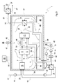
- Fig. 3 shows Fig. 3 another embodiment in which the insulating sheath 31 has at least one inlet opening 46, which may be associated with a non-return valve 47, which opens toward the interior 32 towards.
- the insulation sheath 31 has at least one outlet opening 39, to which, for example, the second supply line 14 is connected. Accordingly, the second oxidizer supply device 13 can suck the oxidizer gas through the outlet port 39 from the inner space 32. This will ensures a certain flushing of the interior 32, which prevents that within the interior 32, a critical concentration of fuel gas can arise, which can get into the interior 32 due to leaks.
- the outlet opening 39 may be associated with a non-return valve 45, which blocks towards the interior 32 and which may be arranged, for example, in the second supply line 14.
- the interior 32 forms part of a gas path, via which the reformer 16 is supplied with oxidizer gas.
- This can basically be used to preheat the oxidizer gas.
- the gas path in the interior 32 is specifically guided so that the oxidizer gas depending on the operating state of the fuel cell system 1 on the one hand the residual gas burner 20 and / or the main heat exchanger 24 and on the other hand the fuel cell 2 and / or the reformer 16 heat can escape when it flows through the interior 32.
- the temperature level of the oxidizer gas can be increased, which favors the operation of the fuel cell system 1.
- FIG. 1 shows Fig. 1
- the individual components of the fuel cell system 1 are cooled and have substantially the same temperature, namely preferably ambient temperature.
- the controller 43 actuates the valves 37, 38 associated with the intake ports 34, 35 so that the first intake port 34 is opened while the second intake port 35 is locked.
- the oxidizer gas is thus sucked into the inner space 32 exclusively via the first inlet opening 34.
- flow guide elements 48 are arranged, which guide the gas path in the interior 32 so that the residual gas burner 22 and here the main heat exchanger 24 is flowed by the sucked oxidizer gas or flows around before it leaves the interior 32 again via the outlet opening 39.
- a corresponding flow situation is in Fig.
- the residual gas burner 20 heats up much faster than the fuel cell 2 and the reformer 16. Accordingly, can be withdrawn by the application of the residual gas burner 20 with oxidant gas to the residual gas burner 20 heat that can be used to preheat the oxidizer gas. Since the main heat exchanger 24 directly adjoins the residual gas burner 20, and the main heat exchanger 24 is heated comparatively quickly, so that the flow around the main heat exchanger 24 can be used to increase the temperature of the oxidizing gas.
- Fig. 2 now shows a normal operating state or a warm start operating state of the fuel cell system 1.
- the controller 23 actuates the valves 37, 38 so that the first inlet opening 34 is blocked is while the second inlet port 35 is opened.
- This switching position can also be realized for the normal operating state of the fuel cell system 1. In this switching position, the oxidant gas is thus sucked exclusively through the second inlet opening 35, whereby, in particular in conjunction with the flow guide elements 48, a targeted flow and flow around the fuel cell 2 and here also the reformer 16 can form.
- the oxidizer gas can absorb heat from the reformer 16 and from the fuel cell 2, which raises the temperature level of the oxidizer gas.
- the time until reaching the operating temperature of the fuel cell 2 can thereby be shortened.
- the fuel cell 2 can be cooled by this flow guide, as well as the reformer 16th
- Fig. 3 an embodiment in which the location for the inlet of the oxidizer gas or the guidance of the oxidizer gas within the insulation sheath 31 is not controllable.
- the gas path in the interior space 31 is specifically designed such that the oxidizing gas flowing in via the at least one inlet opening 46 both is coupled to the fuel cell 2 and the residual gas burner 20 to transmit heat.
- the inflowing oxidizer gas is additionally coupled in a heat-transmitting manner to the reformer 16 and / or to the main heat exchanger 24.
- Such a flow or flow around the said components can also be realized by means of flow guide elements 48.
- This embodiment is characterized in that during the cold start operation, the arrival or flow around the residual gas burner 20 and possibly the Haupttownauertragers 24 can significantly increase the temperature level of the oxidizer gas.
- a temperature increase in the oxidant gas or a cooling for the reformer 16 and the fuel cell 2 can also be achieved during the warm start operation or during normal operation by the arrival or flow around the fuel cell 2 and optionally the reformer 16.
- the embodiment shown operates less efficiently than that in FIGS Fig. 1 and 2 shown embodiment, but is feasible with a reduced effort.
- the first oxidizer supply device 3 can directly suck in the oxidizer gas or the cathode gas from the environment 36.
- the first oxidizer supply device 3 sucks the cathode gas out of the interior 32 of the insulation sheath 31.
- the first supply line 11 is then connected on the input side to the outlet opening 39.
- an embodiment is conceivable in which only the first supply line 11 is connected to the outlet opening 39 and in which the second oxidizer supply device 13 directly sucks the oxidizer gas from the environment 36.
Landscapes
- Engineering & Computer Science (AREA)
- Chemical & Material Sciences (AREA)
- Life Sciences & Earth Sciences (AREA)
- Manufacturing & Machinery (AREA)
- Sustainable Development (AREA)
- Sustainable Energy (AREA)
- Chemical Kinetics & Catalysis (AREA)
- Electrochemistry (AREA)
- General Chemical & Material Sciences (AREA)
- Fuel Cell (AREA)
- Combustion & Propulsion (AREA)
Abstract
Description
- Die vorliegende Erfindung betrifft ein Brennstoffzellensystem, insbesondere in einem Kraftfahrzeug.
- Üblicherweise umfasst ein Brennstoffzellensystem zumindest eine Brennstoffzelle zum Generieren von elektrischem Strom aus Wasserstoffgas enthaltendem Anodengas und Sauerstoffgas enthaltendem Kathodengas. Ferner kann ein solches Brennstoffzellensystem einen Reformer zum Generieren von Wasserstoffgas enthaltendem Anodengas aus Wasserstoff enthaltendem Kraftstoff und Sauerstoff enthaltendem Oxidatorgas umfassen. Um die thermische Effizienz des Brennstoffzellensystems zu verbessern, ist es grundsätzlich möglich, eine thermisch isolierende Isolationshülle vorzusehen, die einen Innenraum umhüllt, in dem zumindest die Brennstoffzelle angeordnet ist. Optional kann in diesem Innenraum auch der Reformer angeordnet sein.
- Aus der
EP 1 624 516 A1 ist ein Brennstoffzellensystem bekannt, bei dem die Brennstoffzelle in einem Einbauraum angeordnet ist, aus dem Kathodengas zur Versorgung der Brennstoffzelle angesaugt wird. Hierdurch kann die Bildung eines explosiven Gemisches in diesem Einbauraum bzw. in der jeweiligen Umgebung des Brennstoffzellensystems reduziert werden. Ein derartiges explosives Gemisch kann durch Leckagen entstehen, durch die Brenngas in die Umgebung des Brennstoffzellensystems bzw. in den Einbauraum gelangt. - Die vorliegende Erfindung beschäftigt sich dem Problem, für ein Brennstoffzellensystem der eingangs genannten Art eine verbesserte Ausführungsform anzugeben, die sich insbesondere durch einen erhöhten Wirkungsgrad auszeichnet.
- Dieses Problem wird erfindungsgemäß durch die Gegenstände der unabhängige Ansprüche gelöst. Vorteilhafte Ausführungsformen sind Gegenstand der abhängigen Ansprüche.
- Die Erfindung beruht auf dem allgemeinen Gedanken, den von der Isolationshülle umhüllten Innenraum in den Gaspfad zur Versorgung der Brennstoffzelle mit Kathodengas bzw. in den Gaspfad zur Versorgung des Reformers mit Oxidatorgas zu integrieren und so auszugestalten, dass das Kathodengas bzw. des Oxidatorgas der Brennstoffzelle und/oder dem Reformer Wärme entzieht, bevor es in die Brennstoffe bzw. in den Reformer eintritt. Auf diese Weise lässt sich einerseits eine Kühlung der Brennstoffzelle bzw. des Reformers erzielen, während andererseits eine Vorwärmung des Kathodengases bzw. des Oxidatorgases erreicht wird, was den Brennstoffzellenprozess bzw. den Reformerprozess begünstigt. Diese Vorwärmung des jeweiligen Gases ist insbesondere bei einem Wiederstart oder Warmstart des Brennstoffzellensystems von besonderem Interesse, um das System möglichst rasch auf Betriebstemperatur bringen zu können. Durch den so verkürzten Warmstart lässt sich die Effizienz des Systems erhöhen.
- Entsprechend einer vorteilhaften Ausführungsform kann das Brennstoffzellensystem mit einem Restgasbrenner ausgestattet sein, in dem eine Verbrennung von Wasserstoffgas enthaltendem Anodenabgas mit Sauerstoffgas enthaltendem Kathodenabgas realisierbar ist. Der Gaspfad im Innenraum der Isolationshülle lässt sich nun optional gezielt so führen, dass zumindest das Kathodengas und/oder das Oxidatorgas diesem Restgasbrenner Wärme entzieht, bevor es zur Brennstoffzelle bzw. zum Reformer gelangt. Diese Bauweise unterstützt vor allem einen Neustart oder Kaltstart des Brennstoffzellensystems, bei dem sämtliche Komponenten im wesentlichen Umgebungstemperatur aufweisen. Da bei kalter Brennstoffzelle in dieser keine Umsetzung von Anodengas und Kathodengas erfolgt, lässt sich im Restgasbrenner umso mehr Anodengas mit Kathodengas verbrennen, wodurch eine entsprechend große Abwärme erzielt wird. Diese lässt sich durch die gezielte Gasführung im Innenraum zum Vorwärmen des Kathodengases bzw. des Oxidatorgases nutzen, was die Aufheizung der Brennstoffzelle bzw. des Reformers auf die jeweilige Betriebstemperatur verkürzt. Auch hier führt das verkürzte Hochfahren des Brennstoffzellensystems zu einem erhöhten Wirkungsgrad.
- Die Wärmeübertragung vom Restgasbrenner bzw. von der Brennstoffzelle oder vom Reformer auf das jeweilige Gas kann beispielsweise dadurch realisiert werden, dass das Kathodengas bzw. das Oxidatorgas die jeweilige Komponente anströmt und/oder umströmt, wodurch die Wärmeübertragung auf das strömende Gas begünstigt wird.
- Besonders vorteilhaft ist nun eine Weiterbildung, bei welcher der Gaspfad im Innenraum steuerbar ist, und zwar so, dass zumindest das Kathodengas bzw. das Oxidatorgas während eines Kaltstartbetriebs bevorzugt oder ausschließlich den Restgasbrenner bzw. einen dem Restgasbrenner nachgeordneten Wärmeübertrager beaufschlagt und während eines Warmstartbetriebs bzw. während eines Normalbetriebs bevorzugt oder ausschließlich die Brennstoffzelle bzw. den Reformer beaufschlagt, um Wärme aufzunehmen. Hierdurch lässt sich im System vorhandene Wärme gezielt zur Wirkungsgradsteigerung nutzen.
- Weitere wichtige Merkmale und Vorteile der Erfindung ergeben sich aus den Unteransprüchen, aus den Zeichnungen und aus der zugehörigen Figurenbeschreibung anhand der Zeichnungen.
- Es versteht sich, dass die vorstehend genannten und die nachstehend noch zu erläuternden Merkmale nicht nur in der jeweils angegebenen Kombination, sondern auch in anderen Kombinationen oder in Alleinstellung verwendbar sind, ohne den Rahmen der vorliegenden Erfindung zu verlassen.
- Bevorzugte Ausführungsbeispiele der Erfindung sind in den Zeichnungen dargestellt und werden in der nachfolgenden Beschreibung näher erläutert, wobei sich gleiche Bezugszeichen auf gleiche oder ähnliche oder funktional gleiche Bauteile beziehen.
- Es zeigen, jeweils schematisch,
- Fig. 1
- eine stark vereinfachte, schaltplanartige Prinzipdarstellung eines Brennstoffzellensystem,
- Fig. 2
- eine Darstellung wie in
Fig. 1 , jedoch bei einem anderen Betriebszustand, - Fig. 3
- eine Darstellung wie in
Fig. 1 , jedoch bei einer anderen Ausführungsform. - Entsprechend den
Fig. 1 bis 3 umfasst ein Brennstoffzellensystem 1, das vorzugsweise in einem Kraftfahrzeug angeordnet sein kann, zumindest eine Brennstoffzelle 2 sowie eine (erste) Oxidatorversorgungseinrichtung 3. Die Brennstoffzelle 2 dient in üblicher Weise zum Generieren von Strom aus einem Wasserstoffgas enthaltenden Brenngas und einem Sauerstoffgas enthaltenden Oxidatorgas. Das Brenngas wird dabei einer Anodenseite 4 der Brennstoffzelle 2 zugeführt, während das Oxidatorgas, bei dem es sich zweckmäßig um Luft handelt, einer Kathodenseite 5 der Brennstoffzelle 2 zugeführt wird. In der Brennstoffzelle 2 trennt ein Elektrolyt 6 die Anodenseite 4 von der Kathodenseite 5. Üblicherweise besteht die Brennstoffzelle 2 aus einem Stapel mehrerer Brennstoffzellenelemente, in denen jeweils die Anodenseite 4 durch einen Elektrolyten 6 von der Kathodenseite 5 getrennt ist. Vorzugsweise handelt es sich bei der Brennstoffzelle 2 um eine Hochtemperatur-Brennstoffzelle, die insbesondere als Festkörper-Brennstoffzelle bzw. als SOFC-Brennstoffzelle ausgestaltet sein kann. Ebenso ist es grundsätzlich möglich, die Brennstoffzelle 2 als Niedertemperatur-Brennstoffzelle auszugestalten, die insbesondere eine PEM-Brennstoffzelle sein kann, die mit einer Protonen-Transport-Membran bzw. mit einer Polymer-Elektrolyt-Membran als Elektrolyt 6 arbeitet. Die vorliegende Erfindung ist von besonderer Bedeutung für eine Hochtemperatur-Brennstoffzelle. Die Brennstoffzelle 2 erhält eingangsseitig über eine an die Anodenseite 4 angeschlossene Anodengasleitung 7 ein durch das Brenngas gebildetes Anodengas. Ein Wasserstoffgas enthaltendes Anodenabgas verlässt die Brennstoffzelle 2 ausgangsseitig über eine Anodenabgasleitung 8, die ebenfalls an die Anodenseite 4 angeschlossen ist. Desweiteren erhält die Brennstoffzelle 2 eingangsseitig über eine an die Kathodenseite 5 angeschlossene Kathodengasleitung 9 ein durch das Oxidatorgas gebildetes Kathodengas. Ein Sauerstoffgas enthaltenden Kathodenabgas verlässt die Brennstoffzelle 2 ausgangsseitig über eine Kathodenabgasleitung 10, die hierzu an die Kathodenseite 5 angeschlossen ist. - Die erste Oxidatorversorgungseinrichtung 3 ist zum Zuführen von Oxidatorgas, also insbesondere von Luft, zur Brennstoffzelle 2 ausgestaltet. Hierzu weist die erste Oxidatorversorgungseinrichtung 3 eine (erste) Versorgungsleitung 11 auf, in der eine geeignete (erste) Fördereinrichtung 12, z.B. eine Pumpe oder Gebläse, zum Antreiben des Oxidatorgases angeordnet ist. Die erste Versorgungsleitung 11 bildet hier die Kathodengasleitung 9 und führt somit der Brennstoffzelle 2 das Kathodengas unmittelbar zu.
- Vorzugsweise ist das Brennstoffzellensystem 1 außerdem mit einem Reformer 16 ausgestattet, der zum Erzeugen des Brenngases aus einem Kraftstoff und einem Oxidatorgas, vorzugsweise Luft, dient. Hierzu ist der Reformer 16 eingangsseitig an eine Kraftstoffleitung 17 und an eine Oxidatorleitung 18 angeschlossen. In der Kraftstoffleitung 17 ist eine Fördereinrichtung 19 zum Antreiben des Kraftstoffs angeordnet, z.B. eine Pumpe. Beim Kraftstoff handelt es sich um einen atomaren Wasserstoff enthaltenden Kraftstoff, vorzugsweise um einen Kohlenwasserstoff. Zweckmäßig kann dabei derjenige Kraftstoff verwendet werden, der in einem mit dem Brennstoffzellensystem 1 ausgestatteten Kraftfahrzeug ohnehin zum Betreiben einer Brennkraftmaschine des Fahrzeugs vorhanden ist, also insbesondere Benzin, Diesel, Biodiesel, Erdgas.
- Die Oxidatorleitung 18 führt dem Reformer 16 das Oxidatorgas zu. Zur Versorgung des Reformers 16 mit Oxidatorgas ist im gezeigten Beispiel eine (zweite) Oxidatorversorgungseinrichtung 13 vorgesehen, die in einer (zweiten) Versorgungsleitung 14 eine (zweite) Fördereinrichtung, z.B. eine Pumpe oder ein Gebläse, enthält. Im Beispiel ist die zweite Versorgungsleitung 14 aufgezweigt, nämlich in einen ersten Versorgungsleitungszweig 40 und einen zweiten Versorgungsleitungszweig 41. Der erste Versorgungsleitungszweig 40 bildet hier die Oxidatorleitung 18 zur Versorgung des Reformers 16 mit Oxidatorgas. Zur gezielten Aufteilung des mit der Fördereinrichtung 15 geförderten Oxidatorgases von der gemeinsamen zweiten Versorgungsleitung 14 auf die einzelnen Versorgungsleitungszweige 40, 41 kann eine Ventileinrichtung 42 vorgesehen sein, die über eine entsprechende Steuerung 43 gezielt so betätigbar ist, dass die jeweils erforderliche Oxidatorgasmenge durch den jeweiligen Versorgungsleitungszweig 40, 41 förderbar ist. Die Steuerung 43 ist über entsprechende Steuerleitungen 44 mit den steuerbaren Komponenten des Brennstoffzellensystems 1 auf geeignete Weise verbunden.
- Das Brennstoffzellensystem 1 kann außerdem einen Restgasbrenner 20 aufweisen, der zum Verbrennen von Anodenabgas mit Kathodenabgas ausgestaltet ist. Hierzu ist der Restgasbrenner 20 eingangsseitig an die Anodenabgasleitung 8 und an die Kathodenabgasleitung 10 angeschlossen. Bevorzugt ist der Restgasbrenner 20 mit einem Brennraum 21 ausgestattet, in dem eine Verbrennungsreaktion mit offener Flamme abläuft. Grundsätzlich ist jedoch auch ein Restgasbrenner 20 denkbar, der einen Oxidationskatalysator aufweist und mit katalytischer Verbrennung arbeitet. Ausgangsseitig ist an den Restgasbrenner 20 eine Abgasleitung 22 angeschlossen, über die ein durch die Verbrennungsreaktion gebildetes Brennerabgas vom Restgasbrenner 20 abgeführt wird. Optional kann an den Restgasbrenner 20 eine Kühlgasleitung 23 angeschlossen sein, und zwar insbesondere kathodenseitig. Über die Kühlgasleitung 23 ist bei Bedarf ein Kühlgas, vorzugsweise Luft, dem Restgasbrenner 20 zuführbar. Im gezeigten Beispiel ist die Kühlgasleitung 23 durch den zweiten Versorgungsleitungszweig 41 gebildet.
- Bei den hier gezeigten bevorzugten Ausführungsformen versorgt die erste Oxidatorversorgungseinrichtung 3 nur die Brennstoffzelle 2 mit Oxidatorgas bzw. Kathodengas, während die zweite Oxidatorversorgungseinrichtung 13 den Reformer 16 und den Restgasbrenner 20 mit Oxidatorgas bzw. mit Kühlgas versorgt. Es ist klar, dass bei anderen Ausführungsformen grundsätzlich auch eine gemeinsame Oxidatorversorgungseinrichtung zur Versorgung der Brennstoffzelle 2, des Reformers 16 und des Restgasbrenners 20 mit Oxidatorgas vorgesehen sein kann, beispielsweise kann hierzu die Kathodengasleitung 9 durch einen dritten Versorgungsleitungszweig gebildet sein, der ebenfalls über die Ventileinrichtung 42 ansteuerbar ist.
- Das Brennstoffzellensystem 1 kann desweiteren zumindest einen Wärmeübertrager aufweisen. In den gezeigten Beispielen sind jeweils drei Wärmeübertrager vorgesehen, nämlich ein Hauptwärmeübertrager 24, ein Zusatzwärmeübertrager 25 und ein Rezirkulationswärmeübertrager 26. Der Hauptwärmeübertrager 24 ist einerseits in die Abgasleitung 22 und andererseits in die Kathodengasleitung 9 eingebunden. Der Hauptwärmeübertrager 24 dient zur Übertragung von Wärme vom Brennerabgas auf das Kathodengas. Der Zusatzwärmeübertrager 25 ist einerseits in die Abgasleitung 22 und andererseits in eine Leitung 27 eingebunden, die zu einem grundsätzlich beliebigen Wärmeverbraucher führen kann. Insbesondere kann der Zusatzwärmeübertrager 25 über die Leitung 27 in einen Kühlkreis einer Brennkraftmaschine des mit dem Brennstoffzellensystem 1 ausgestatteten Fahrzeugs oder in einem Heizkreis zum Aufwärmen eines Fahrzeuginnenraums des mit dem Brennstoffzellensystem 1 ausgestatteten Fahrzeugs eingebunden sein. Der Zusatzwärmeübertrager 25 ist in der Abgasleitung 22 stromab des Hauptwärmeübertragers 24 angeordnet und kann dem Brennerabgas zusätzliche Wärme entziehen. Der Rezirkulationswärmeübertrager 26 ist einerseits in die Oxidatorgasleitung 18 bzw. in den ersten Versorgungsleitungszweig 40 und andererseits in eine Rezirkulationsleitung 28 eingebunden. Alternativ kann der Rezirkulationswärmeübertrager 26 auch die Rezirkulationsleitung 28 mit der Kathodengasleitung 9, insbesondere stromauf des Hauptwärmeübertragers 24, wärmeübertragend koppeln. Die Rezirkulationsleitung 28 zweigt bei 29 von der Anodenabgasleitung 8 ab und ist an die Eingangsseite des Reformers 16 angeschlossen. Sie enthält stromab des Rezirkulationswärmeübertragers 26 eine Fördereinrichtung 30 zum Antreiben des rezirkulierten Anodenabgases, bei der es sich beispielsweise um eine Pumpe, ein Gebläse oder einen Kompressor handeln kann. Das Anodenabgas kann je nach Betriebszustand der Brennstoffzelle 2 einen relativ hohen Anteil an Wasserstoffgas enthalten und kann somit durch die Rückführung in den Reformer 16 zur Steigerung des Wirkungsgrads genutzt werden.
- Brennstoffzelle 2, Restgasbrenner 20, Hauptwärmeübertrager 24, Zusatzwärmeübertrager 25 und Rezirkulationswärmeübertrager 26 bilden in den gezeigten Beispielen jeweils separate Komponenten. Grundsätzlich ist es jedoch möglich, zumindest zwei dieser Komponenten baulich zu einer Einheit zu integrieren. Beispielsweise kann der Restgasbrenner 20 in eine Ausgangsseite der Brennstoffzelle 2 integriert werden. Zusätzlich oder alternativ kann der Hauptwärmeübertrager 24 in die Ausgangsseite des Restgasbrenners 20 integriert werden. Ebenso ist es möglich, zwei oder drei dieser Wärmeübertrager 24, 25, 26 zu einer baulichen Einheit zu integrieren.
- Das Brennstoffzellensystem 1 ist außerdem mit einer thermisch isolierenden Isolationshülle 31 ausgestattet, die vorzugsweise ein thermisch isolierendes Material aufweist. Beispielsweise kann es sich um eine Blechbox handeln, die innen und/oder außen mit dem Isolationsmaterial versehen ist. Das von der Isolationshülle 31 umschlossene bzw. umhüllte Volumen bildet einen Innenraum 32, der hier für Komponenten des Brennstoffzellensystems 1 als Einbauraum genutzt wird. Dementsprechend sind im Innenraum 32 zumindest die Brennstoffzelle 2 und optional zumindest eine der Komponenten Reformer 16, Restgasbrenner 20, Hauptwärmeübertrager 24, Rezirkulationswärmeübertrager 26, Fördereinrichtung 30 angeordnet. Ohne Beschränkung der Allgemeinheit sind in den gezeigten Beispielen der Reformer 16, die Brennstoffzelle 2, der Restgasbrenner 20 und der Hauptwärmeübertrager 24 innerhalb der Isolationshülle 31, also im Innenraum 32 angeordnet. Denkbar ist auch eine Ausführungsform, bei der die Isolationshülle 31 aus mehreren Teilhüllen besteht. Der Innenraum 32 besteht dann entsprechend aus mehreren Teil-Innenräumen, die insbesondere miteinander kommunizieren. Beispielsweise kann eine solche Teilhülle zumindest den Reformer 16 umschließen, während eine andere Teilhülle zumindest die Brennstoffzelle 2 und den Restgasbrenner 20 umschließt. In den gezeigten Beispielen sind der Zusatzwärmeübertrager 25 und der Rezirkulationswärmeübertrager 26 sowie die Fördereinrichtungen 12, 15, 19, 30 außerhalb der Isolationshülle 31 angeordnet; ebenso befindet sich zweckmäßig die Steuerung 43 ebenfalls außerhalb der Isolationshülle 31.
- Die Isolationshülle 31 enthält mehrere Durchgangsöffnungen 33, durch welche die Kraftstoffleitung 17, die Abgasleitung 22, die Rezirkulationsleitung 28, die Kühlgasleitung 23 und die Kathodengasleitung 9 durch die Isolationshülle 31 hindurchgeführt sind. Diese Durchführung der genannten Leitungen erfolgen dabei zweckmäßig so, dass die gewünschte thermische Isolierung gewährleistet ist. Außerdem kann in den Durchführungen eine gewünschte Gasdichtigkeit und - falls erforderlich - eine gewünschte Druckdichtigkeit erreicht werden. Insbesondere ist im Bereich der mit den entsprechenden Anschlüssen versehenen Eingangsseite des Reformers 16 die zugehörige Durchgangsöffnung 33 so gestaltet, dass zumindest die Kraftstoffleitung 17 direkt an den Reformer 16 anschließbar ist, ohne dass sich die Kraftstoffleitung 17 dabei innerhalb des Innenraums 32 erstreckt. Vorzugsweise bildet ein Abschnitt der Reformereingangsseite einen Teil der Isolationshülle 31.
- Bei den gezeigten Beispielen verlaufen bzw. liegen Teile des Brennstoffzellensystems 1 außerhalb der Isolationshülle 31, wie z.B. Abschnitte der Versorgungsleitungen 11, 14 sowie der Rezirkulationsleitung 28 und der Rezirkulationswärmeübertrager 26. Denkbar ist auch eine Ausführungsform, bei welcher die genannten Teile vollständig oder wenigstens weitgehend innerhalb der Isolationshülle 31 angeordnet sind.
- Bei der in den
Fig. 1 und2 gezeigten Ausführungsform weist die Isolationshülle 31 außerdem zwei Einlassöffnungen, nämlich eine erste Einlassöffnung 34 und eine zweite Einlassöffnung 35 auf, durch die Oxidatorgas, also vorzugsweise Luft aus einer Umgebung 36 des Brennstoffzellensystems 1 in den Innenraum 32 der Isolationshülle 31 gelangt. Bei dieser Ausführungsform sind die beiden Einlassöffnungen 34, 35 jeweils mittels eines Ventils 37 bzw. 38 schaltbar. Die Ventile 37, 38 sind hierzu auf geeignete Weise mit der Steuerung 43 verbunden. Im Unterschied zu der in denFig. 1 und2 gezeigten Ausführungsform, die sich zumindest durch zwei beabstandete bzw. durch zwei separat schaltbare Einlassöffnungen 34, 35 auszeichnet, zeigtFig. 3 eine andere Ausführungsform, bei welcher die Isolationshülle 31 zumindest eine Einlassöffnung 46 aufweist, der ein Rückschlagsperrventil 47 zugeordnet sein kann, das in Richtung zum Innenraum 32 hin öffnet. - Ferner besitzt die Isolationshülle 31 zumindest eine Auslassöffnung 39, an welche z.B. die zweite Versorgungsleitung 14 angeschlossen ist. Dementsprechend kann die zweite Oxidatorversorgungseinrichtung 13 das Oxidatorgas durch die Auslassöffnung 39 aus dem Innenraum 32 ansaugen. Hierdurch wird eine gewisse Spülung des Innenraums 32 gewährleistet, die verhindert, dass innerhalb des Innenraums 32 eine kritische Konzentration an Brenngas entstehen kann, das aufgrund von Leckagen in den Innenraum 32 gelangen kann. Bevorzugt kann auch der Auslassöffnung 39 ein Rückschlagsperrventil 45 zugeordnet sein, das zum Innenraum 32 hin sperrt und das z.B. in der zweiten Versorgungsleitung 14 angeordnet sein kann.
- Durch das Anschließen der zweiten Versorgungsleitung 14 an die Auslassöffnung 39 und durch die an der Isolationshülle 31 vorgesehenen Einlassöffnungen 34, 35 bzw. 46 bildet der Innenraum 32 einen Bestandteil eines Gaspfads, über den der Reformer 16 mit Oxidatorgas versorgt wird. Dies kann grundsätzlich zum Vorwärmen des Oxidatorgases genutzt werden. Hierzu ist bei den Brennstoffzellensystemen 1 der hier gezeigten Ausführungsformen der Gaspfad im Innenraum 32 gezielt so geführt, dass das Oxidatorgas je nach Betriebszustand des Brennstoffzellensystems 1 einerseits dem Restgasbrenner 20 und/oder dem Hauptwärmeübertrager 24 und andererseits der Brennstoffzelle 2 und/oder dem Reformer 16 Wärme entziehen kann, wenn es den Innenraum 32 durchströmt. Hierdurch kann das Temperaturniveau des Oxidatorgases erhöht werden, was den Betrieb des Brennstoffzellensystems 1 begünstigt.
- Beispielsweise zeigt
Fig. 1 einen Kaltstartbetriebszustand des Brennstoffzellensystems 1. Beim Kaltstart sind die einzelnen Komponenten des Brennstoffzellensystems 1 ausgekühlt und weisen im wesentlichen die gleiche Temperatur, nämlich vorzugsweise Umgebungstemperatur auf. Während des Kaltstartbetriebs betätigt die Steuerung 43 die den Einlassöffnungen 34, 35 zugeordneten Ventile 37, 38 so, dass die erste Einlassöffnung 34 geöffnet ist, während die zweite Einlassöffnungen 35 gesperrt ist. Das Oxidatorgas wird somit ausschließlich über die erste Einlassöffnung 34 in den Innenraum 32 eingesaugt. Im Innenraum 32 sind nun Strömungsleitelemente 48 angeordnet, die den Gaspfad im Innenraum 32 so führen, dass der Restgasbrenner 22 und hier auch der Hauptwärmeübertrager 24 vom angesaugten Oxidatorgas angeströmt bzw. umströmt werden, bevor es über die Auslassöffnung 39 den Innenraum 32 wieder verlässt. Eine entsprechende Strömungssituation ist inFig. 1 durch nicht näher bezeichnete Pfeile angedeutet. Während des Kaltstartbetriebs heizt sich der Restgasbrenner 20 deutlich schneller auf als die Brennstoffzelle 2 und der Reformer 16. Dementsprechend kann durch die Beaufschlagung des Restgasbrenners 20 mit Oxidatorgas dem Restgasbrenner 20 Wärme entzogen werden, die zur Vorwärmung des Oxidatorgases genutzt werden kann. Da sich der Hauptwärmeübertrager 24 unmittelbar an den Restgasbrenner 20 anschließt, wird auch der Hauptwärmeübertrager 24 vergleichsweise rasch aufgeheizt, so dass auch die Umströmung des Hauptwärmeübertragers 24 zur Temperaturerhöhung des Oxidatorgases genutzt werden kann. -
Fig. 2 zeigt nun einen Normalbetriebszustand bzw. einen Warmstartbetriebszustand des Brennstoffzellensystems 1. Beim Warmstart sind diejenigen Komponenten des Brennstoffzellensystems 1, die eine vergleichsweise hohe Wärmekapazität aufweisen, noch vergleichsweise heiß. Dies sind vor allem die Brennstoffzelle 2 und auch der Reformer 16. Im Unterschied dazu kann der Restgasbrenner 20 vergleichsweise rasch auskühlen, ebenso wie der Hauptwärmeübertrager 24. Für diesen Warmstartbetrieb betätigt die Steuerung 23 die Ventile 37, 38 so, dass die erste Einlassöffnung 34 gesperrt ist, während die zweite Einlassöffnung 35 geöffnet ist. Diese Schaltstellung kann auch für den Normalbetriebszustand des Brennstoffzellensystems 1 realisiert werden. Bei dieser Schaltstellung wird das Oxidatorgas somit ausschließlich durch die zweite Einlassöffnung 35 angesaugt, wodurch sich, insbesondere in Verbindung mit den Strömungsleitelementen 48 eine gezielte Anströmung und Umströmung der Brennstoffzelle 2 sowie hier auch des Reformers 16 ausbilden kann. Dementsprechend kann das Oxidatorgas Wärme vom Reformer 16 und von der Brennstoffzelle 2 aufnehmen, was das Temperaturniveau des Oxidatorgases erhöht. Für den Warmstartbetrieb kann dadurch die Zeit bis zum Erreichen der Betriebstemperatur der Brennstoffzelle 2 verkürzt werden. Während des Normalbetriebs kann durch diese Strömungsführung die Brennstoffzelle 2 gekühlt werden, ebenso wie der Reformer 16. - Im Unterschied zur Ausführungsform der
Fig. 1 und2 zeigtFig. 3 eine Ausführungsform, bei welcher der Ort für den Einlass des Oxidatorgases bzw. die Führung des Oxidatorgases innerhalb der Isolationshülle 31 nicht steuerbar ist. Dafür ist bei der inFig. 3 gezeigten Ausführungsform der Gaspfad im Innenraum 31 gezielt so gestaltet, dass das über die wenigstens eine Einlassöffnung 46 einströmende Oxidatorgas sowohl mit der Brennstoffzelle 2 als auch mit dem Restgasbrenner 20 wärmeübertragend gekoppelt ist. Optional kann auch vorgesehen sein, dass das einströmende Oxidatorgas zusätzlich mit dem Reformer 16 und/oder mit dem Hauptwärmeübertrager 24 wärmeübertragend gekoppelt ist. Eine derartige Anströmung bzw. Umströmung der genannten Komponenten kann ebenfalls mittels Strömungsleitelementen 48 realisiert werden. Diese Ausführungsform zeichnet sich dadurch aus, dass während des Kaltstartbetriebs die An- bzw. Umströmung des Restgasbrenners 20 sowie gegebenenfalls des Hauptwärmeübertragers 24 das Temperaturniveau des Oxidatorgases signifikant erhöhen kann. Im Unterschied dazu kann während des Warmstartbetriebs bzw. während des Normalbetriebs durch die An- bzw. Umströmung der Brennstoffzelle 2 und gegebenenfalls des Reformers 16 ebenfalls eine Temperaturerhöhung im Oxidatorgas bzw. eine Kühlung für den Reformer 16 bzw. die Brennstoffzelle 2 erreicht werden. Die inFig. 3 gezeigte Ausführungsform arbeitet weniger effizient als die in denFig. 1 und2 gezeigte Ausführungsform, ist jedoch mit einem reduzierten Aufwand realisierbar. - Insbesondere kann wie bei den hier gezeigten Ausführungsformen die erste Oxidatorversorgungseinrichtung 3 das Oxidatorgas bzw. das Kathodengas aus der Umgebung 36 direkt ansaugen. Ebenso ist eine Ausführungsform möglich, bei welcher auch die erste Oxidatorversorgungseinrichtung 3 das Kathodengas aus dem Innenraum 32 der Isolationshülle 31 ansaugt. Beispielsweise ist dann auch die erste Versorgungsleitung 11 eingangsseitig an die Auslassöffnung 39 angeschlossen. Ebenso ist grundsätzlich eine Ausführungsform denkbar, bei der ausschließlich die erste Versorgungsleitung 11 an die Auslassöffnung 39 angeschlossen ist und bei der die zweite Oxidatorversorgungseinrichtung 13 das Oxidatorgas aus der Umgebung 36 direkt ansaugt.
Claims (10)
- Brennstoffzellensystem, insbesondere in einem Kraftfahrzeug,- mit wenigstens einer Brennstoffzelle (2) zum Generieren von elektrischem Strom aus einem Wasserstoffgas enthaltenden Anodengas und einem Sauerstoffgas enthaltenden Kathodengas,- mit einer thermisch isolierenden Isolationshülle (31), die einen zumindest die Brennstoffzelle (2) aufnehmenden Innenraum (32) umhüllt,- wobei ein Gaspfad zur Versorgung der Brennstoffzelle (2) mit Kathodengas durch die Isolationshülle (31) hindurchgeführt ist, derart, dass deren Innenraum (32) einen Bestandteil des Gaspfads bildet,- wobei der Gaspfad im Innenraum (32) so verläuft, dass das Kathodengas der Brennstoffzelle (2) Wärme entzieht, bevor es in die Brennstoffzelle (2) eintritt.
- Brennstoffzellensystem nach Anspruch 1,
dadurch gekennzeichnet,
dass der Gaspfad im Innenraum (32) so verläuft, dass das Kathodengas die Brennstoffzelle (2) anströmt und/oder umströmt, bevor es in die Brennstoffzelle (2) eintritt. - Brennstoffzellensystem, insbesondere in einem Kraftfahrzeug,- mit einem Reformer (16) zum Genieren von Wasserstoffgas enthaltendem Anodengas aus einem Wasserstoff enthaltenden Kraftstoff und einem Sauerstoff enthaltenden Oxidatorgas,- mit wenigstens einer Brennstoffzelle (2) zum Generieren von elektrischem Strom aus dem Anodengas und einem Sauerstoffgas enthaltenden Kathodengas,- mit einer thermisch isolierenden Isolationshülle (31), die einen zumindest die Brennstoffzelle und/oder den Reformer (16) aufnehmenden Innenraum (32) umhüllt,- wobei ein Gaspfad zur Versorgung der Brennstoffzelle (2) mit Kathodengas und/oder zur Versorgung des Reformers (16) mit Oxidatorgas durch die Isolationshülle (31) hindurchgeführt ist, derart, dass deren Innenraum (32) einen Bestandteil des Gaspfads bildet,- wobei der Gaspfad im Innenraum (32) so verläuft, dass das Kathodengas und/oder das Oxidatorgas dem Reformer (16) und/oder der Brennstoffzelle (2) Wärme entzieht, bevor es in die Brennstoffzelle (2) und/oder in den Reformer (16) eintritt.
- Brennstoffzellensystem nach Anspruch 3,
dadurch gekennzeichnet,
dass der Gaspfad im Innenraum (32) so verläuft, dass das Kathodengas und/oder das Oxidatorgas die Brennstoffzelle (2) und/oder den Reformer (16) anströmt und/oder umströmt, bevor es in den Reformer (16) und/oder in die Brennstoffzelle (2) eintritt. - Brennstoffzellensystem nach einem der Ansprüche 1 bis 4,
dadurch gekennzeichnet,- dass im Innenraum (32) ein Restgasbrenner (20) angeordnet ist, der im Betrieb Wasserstoffgas enthaltendes Anodenabgas mit Sauerstoffgas enthaltendem Kathodenabgas verbrennt,- dass der Gaspfad im Innenraum (32) so verläuft, dass das Kathodengas und/oder das Oxidatorgas dem Restgasbrenner (20) Wärme entzieht, bevor es in den Reformer (16) und/oder in die Brennstoffzelle (2) eintritt. - Brennstoffzellensystem nach Anspruch 5,
dadurch gekennzeichnet,
dass der Gaspfad im Innenraum (32) so verläuft, dass das Oxidatorgas und/oder das Kathodengas den Restgasbrenner (20) umströmt und/oder anströmt, bevor es in den Reformer (16) und/oder in die Brennstoffzelle (2) eintritt. - Brennstoffzellensystem nach Anspruch 5 oder 6,
dadurch gekennzeichnet,- dass im Innenraum (32) ein Wärmeübertrager (24) zur wärmeübertragenden Kopplung von Brennerabgas des Restgasbrenners (20) mit Kathodengas und/oder Oxidatorgas angeordnet ist,- dass der Gaspfad im Innenraum (32) so verläuft, dass das Kathodengas und/oder das Oxidatorgas dem Wärmeübertrager (24) Wärme entzieht, bevor es in den Wärmeübertrager (24) und/oder in den Reformer (16) und/oder in die Brennstoffzelle (2) eintritt, wobei der Gaspfad im Innenraum (32) insbesondere so verlaufen kann, dass das Oxidatorgas und/oder das Kathodengas den Wärmeübertrager (24) anströmt und/oder umströmt bevor es in den Wärmeübertrager (24) und/oder in den Reformer (16) und/oder in die Brennstoffzelle (2) eintritt. - Brennstoffzellensystem nach einem der Ansprüche 5 bis 7,
dadurch gekennzeichnet,
dass der Gaspfad im Innenraum (32) so verläuft, dass das Oxidatorgas und/oder das Kathodengas sowohl den Restgasbrenner (20) als auch die Brennstoffzelle (2) beaufschlagt, bevor es in den Reformer (16) und/oder in die Brennstoffzelle (2) eintritt. - Brennstoffzellensystem nach einem der Ansprüche 5 bis 7,
dadurch gekennzeichnet,
dass der Gaspfad steuerbar ist, derart, dass das Oxidatorgas und/oder das Kathodengas bei einem Kaltstartbetrieb bevorzugt oder ausschließlich den Restgasbrenner (20) und/oder den Wärmeübertrager (24) beaufschlagt und bei einem Warmstartbetrieb oder bei einem Normalbetrieb bevorzugt oder ausschließlich die Brennstoffzelle (2) und/oder den Reformer (16) beaufschlagt. - Brennstoffzellensystem nach einem der Ansprüche 1 bis 9,
dadurch gekennzeichnet,- dass die Isolationshülle (31) gasdicht und/oder druckdicht ausgestaltet ist, und/oder- dass im Innenraum (32) Strömungsleitelemente (48) angeordnet sind, um den Gaspfad zur Beaufschlagung der Brennstoffzelle (2) und/oder des Restgasbrenners (20) und/oder des Reformers (16) und/oder des Wärmeübertragers (24) zu führen.
Applications Claiming Priority (1)
| Application Number | Priority Date | Filing Date | Title |
|---|---|---|---|
| DE102007039017A DE102007039017A1 (de) | 2007-08-17 | 2007-08-17 | Brennstoffzellensystem |
Publications (2)
| Publication Number | Publication Date |
|---|---|
| EP2028709A1 true EP2028709A1 (de) | 2009-02-25 |
| EP2028709B1 EP2028709B1 (de) | 2011-10-19 |
Family
ID=39930814
Family Applications (1)
| Application Number | Title | Priority Date | Filing Date |
|---|---|---|---|
| EP08162157A Not-in-force EP2028709B1 (de) | 2007-08-17 | 2008-08-11 | Brennstoffzellensystem |
Country Status (3)
| Country | Link |
|---|---|
| EP (1) | EP2028709B1 (de) |
| AT (1) | ATE529912T1 (de) |
| DE (1) | DE102007039017A1 (de) |
Cited By (1)
| Publication number | Priority date | Publication date | Assignee | Title |
|---|---|---|---|---|
| EP2963725A1 (de) * | 2014-06-30 | 2016-01-06 | Aisin Seiki Kabushiki Kaisha | Brennstoffzellensystem |
Families Citing this family (3)
| Publication number | Priority date | Publication date | Assignee | Title |
|---|---|---|---|---|
| CN102035002B (zh) * | 2010-11-30 | 2013-01-30 | 新源动力股份有限公司 | 一种具有水热管理能力的燃料电池模块 |
| AT523668B1 (de) * | 2020-03-30 | 2021-12-15 | Avl List Gmbh | Brennstoffzellensystem und Verfahren zum Betreiben eines Brennstoffzellensystems |
| DE102021214812A1 (de) | 2021-12-21 | 2023-06-22 | Robert Bosch Gesellschaft mit beschränkter Haftung | Brennstoffzellenvorrichtung |
Citations (6)
| Publication number | Priority date | Publication date | Assignee | Title |
|---|---|---|---|---|
| EP0374636A1 (de) * | 1988-12-20 | 1990-06-27 | Asea Brown Boveri Ag | Verfahren zur Umwandlung von in einem Stoff als chemisches Potential vorliegender Energie in elektrische Energie basierend auf einem elektrochemischen Hochtemperaturprozess |
| EP0654838A1 (de) * | 1993-11-24 | 1995-05-24 | Sulzer Innotec Ag | Einrichtung mit Hochtemperatur-Brennstoffzellen und Verfahren zum Anfahrbetrieb der Einrichtung |
| DE4446841A1 (de) * | 1994-12-27 | 1996-07-04 | Mtu Friedrichshafen Gmbh | Brennstoffzellenmodul |
| DE19910695C1 (de) * | 1999-03-10 | 2000-08-10 | Siemens Ag | Verfahren zum Betreiben einer Brennstoffzellenanlage und Brennstoffzellenanlage |
| EP1347529A2 (de) * | 2002-03-19 | 2003-09-24 | Sulzer Hexis AG | Brennstoffzellenbatterie mit integriertem Wärmetauscher |
| EP1624516A1 (de) | 2004-08-02 | 2006-02-08 | Siemens Aktiengesellschaft | Verfahren zum Betreiben einer in einem Einbauraum angeordneten und mit einem Brenngas und mit Luft betriebenen Brennstoffzellenanlage sowie Anordnung zur Durchführung des Verfahrens |
Family Cites Families (2)
| Publication number | Priority date | Publication date | Assignee | Title |
|---|---|---|---|---|
| AT407590B (de) * | 1998-10-08 | 2001-04-25 | Vaillant Gmbh | Blockheizkraftwerk |
| DE102006031866A1 (de) * | 2006-07-10 | 2008-01-17 | Webasto Ag | Brennstoffzellensystem und Verfahren zum Beeinflussen des Wärmehaushaltes eines Brennstoffzellensystems |
-
2007
- 2007-08-17 DE DE102007039017A patent/DE102007039017A1/de not_active Withdrawn
-
2008
- 2008-08-11 AT AT08162157T patent/ATE529912T1/de active
- 2008-08-11 EP EP08162157A patent/EP2028709B1/de not_active Not-in-force
Patent Citations (6)
| Publication number | Priority date | Publication date | Assignee | Title |
|---|---|---|---|---|
| EP0374636A1 (de) * | 1988-12-20 | 1990-06-27 | Asea Brown Boveri Ag | Verfahren zur Umwandlung von in einem Stoff als chemisches Potential vorliegender Energie in elektrische Energie basierend auf einem elektrochemischen Hochtemperaturprozess |
| EP0654838A1 (de) * | 1993-11-24 | 1995-05-24 | Sulzer Innotec Ag | Einrichtung mit Hochtemperatur-Brennstoffzellen und Verfahren zum Anfahrbetrieb der Einrichtung |
| DE4446841A1 (de) * | 1994-12-27 | 1996-07-04 | Mtu Friedrichshafen Gmbh | Brennstoffzellenmodul |
| DE19910695C1 (de) * | 1999-03-10 | 2000-08-10 | Siemens Ag | Verfahren zum Betreiben einer Brennstoffzellenanlage und Brennstoffzellenanlage |
| EP1347529A2 (de) * | 2002-03-19 | 2003-09-24 | Sulzer Hexis AG | Brennstoffzellenbatterie mit integriertem Wärmetauscher |
| EP1624516A1 (de) | 2004-08-02 | 2006-02-08 | Siemens Aktiengesellschaft | Verfahren zum Betreiben einer in einem Einbauraum angeordneten und mit einem Brenngas und mit Luft betriebenen Brennstoffzellenanlage sowie Anordnung zur Durchführung des Verfahrens |
Cited By (2)
| Publication number | Priority date | Publication date | Assignee | Title |
|---|---|---|---|---|
| EP2963725A1 (de) * | 2014-06-30 | 2016-01-06 | Aisin Seiki Kabushiki Kaisha | Brennstoffzellensystem |
| JP2016012531A (ja) * | 2014-06-30 | 2016-01-21 | アイシン精機株式会社 | 燃料電池システム |
Also Published As
| Publication number | Publication date |
|---|---|
| ATE529912T1 (de) | 2011-11-15 |
| DE102007039017A1 (de) | 2009-02-19 |
| EP2028709B1 (de) | 2011-10-19 |
Similar Documents
| Publication | Publication Date | Title |
|---|---|---|
| EP1616361B1 (de) | Energieumwandlungsvorrichtung sowie reformereinrichtung und brennstoffzelleneinrichtung hierfür | |
| DE102011088563B4 (de) | Anordnung mit Brennstoffzellensystem | |
| DE19931061A1 (de) | Anordnung zum Beheizen/Kühlen einer Brennstoffzelle und Brennstoffzellensystem | |
| DE102008018152B4 (de) | Brennstoffzellensystem und zugehöriges Betriebsverfahren | |
| EP1679757B1 (de) | Brennstoffzellensystem | |
| EP2028709B1 (de) | Brennstoffzellensystem | |
| EP2058885B1 (de) | Brennstoffzellensystem | |
| EP1947723B1 (de) | Energiebereitstellungssystem | |
| DE19931062B4 (de) | Anordnung zum Beheizen/Kühlen einer Brennstoffzelle und Brennstoffzellensystem und deren Verwendung | |
| EP1986263B1 (de) | Brennstoffzellensystem und zugehöriges Startverfahren | |
| EP1845576B1 (de) | Brennstoffzellensystem | |
| DE102012220082A1 (de) | Fahrzeugbrennstoffzellensystem und zugehöriges Betriebsverfahren | |
| DE102021126708B3 (de) | Verfahren zum Starten einer Festoxidbrennstoffzellenvorrichtung sowie Brennstoffzellenfahrzeug | |
| DE102008008907B4 (de) | Brennstoffzellensystem | |
| EP1968150B1 (de) | Brennstoffzellensystem | |
| EP1845577B1 (de) | Brennstoffzellensystem | |
| WO2008000201A1 (de) | Brennstoffzellensystem | |
| DE102007054768A1 (de) | Reformer, Brennstoffzelle und zugehörige Betriebsverfahren | |
| EP2075225B1 (de) | Reformer, Brennstoffzellensystem und zugehöriges Betriebsverfahren | |
| DE102005030474A1 (de) | Brennstoffzellensystem für ein Fahrzeug | |
| AT527535A1 (de) | Brennstoffzellensystem für ein Erzeugen eines Synthesegases | |
| DE112019005805T5 (de) | Kompakte Brenner/Reformer-Einheit für ein Brennstoffzellensystem sowie deren Verwendung und Funktionsweise | |
| DE102007040192A1 (de) | Reformer und Brennstoffzellensystem |
Legal Events
| Date | Code | Title | Description |
|---|---|---|---|
| PUAI | Public reference made under article 153(3) epc to a published international application that has entered the european phase |
Free format text: ORIGINAL CODE: 0009012 |
|
| AK | Designated contracting states |
Kind code of ref document: A1 Designated state(s): AT BE BG CH CY CZ DE DK EE ES FI FR GB GR HR HU IE IS IT LI LT LU LV MC MT NL NO PL PT RO SE SI SK TR |
|
| AX | Request for extension of the european patent |
Extension state: AL BA MK RS |
|
| AKX | Designation fees paid |
Designated state(s): AT BE BG CH CY CZ DE DK EE ES FI FR GB GR HR HU IE IS IT LI LT LU LV MC MT NL NO PL PT RO SE SI SK TR |
|
| 17P | Request for examination filed |
Effective date: 20090825 |
|
| 17Q | First examination report despatched |
Effective date: 20100312 |
|
| GRAP | Despatch of communication of intention to grant a patent |
Free format text: ORIGINAL CODE: EPIDOSNIGR1 |
|
| GRAS | Grant fee paid |
Free format text: ORIGINAL CODE: EPIDOSNIGR3 |
|
| GRAA | (expected) grant |
Free format text: ORIGINAL CODE: 0009210 |
|
| AK | Designated contracting states |
Kind code of ref document: B1 Designated state(s): AT BE BG CH CY CZ DE DK EE ES FI FR GB GR HR HU IE IS IT LI LT LU LV MC MT NL NO PL PT RO SE SI SK TR |
|
| REG | Reference to a national code |
Ref country code: GB Ref legal event code: FG4D Free format text: NOT ENGLISH |
|
| REG | Reference to a national code |
Ref country code: CH Ref legal event code: EP |
|
| REG | Reference to a national code |
Ref country code: IE Ref legal event code: FG4D |
|
| REG | Reference to a national code |
Ref country code: DE Ref legal event code: R096 Ref document number: 502008005242 Country of ref document: DE Effective date: 20120126 |
|
| REG | Reference to a national code |
Ref country code: NL Ref legal event code: VDEP Effective date: 20111019 |
|
| LTIE | Lt: invalidation of european patent or patent extension |
Effective date: 20111019 |
|
| PG25 | Lapsed in a contracting state [announced via postgrant information from national office to epo] |
Ref country code: NO Free format text: LAPSE BECAUSE OF FAILURE TO SUBMIT A TRANSLATION OF THE DESCRIPTION OR TO PAY THE FEE WITHIN THE PRESCRIBED TIME-LIMIT Effective date: 20120119 Ref country code: IS Free format text: LAPSE BECAUSE OF FAILURE TO SUBMIT A TRANSLATION OF THE DESCRIPTION OR TO PAY THE FEE WITHIN THE PRESCRIBED TIME-LIMIT Effective date: 20120219 Ref country code: LT Free format text: LAPSE BECAUSE OF FAILURE TO SUBMIT A TRANSLATION OF THE DESCRIPTION OR TO PAY THE FEE WITHIN THE PRESCRIBED TIME-LIMIT Effective date: 20111019 |
|
| REG | Reference to a national code |
Ref country code: IE Ref legal event code: FD4D |
|
| PG25 | Lapsed in a contracting state [announced via postgrant information from national office to epo] |
Ref country code: NL Free format text: LAPSE BECAUSE OF FAILURE TO SUBMIT A TRANSLATION OF THE DESCRIPTION OR TO PAY THE FEE WITHIN THE PRESCRIBED TIME-LIMIT Effective date: 20111019 Ref country code: GR Free format text: LAPSE BECAUSE OF FAILURE TO SUBMIT A TRANSLATION OF THE DESCRIPTION OR TO PAY THE FEE WITHIN THE PRESCRIBED TIME-LIMIT Effective date: 20120120 Ref country code: PT Free format text: LAPSE BECAUSE OF FAILURE TO SUBMIT A TRANSLATION OF THE DESCRIPTION OR TO PAY THE FEE WITHIN THE PRESCRIBED TIME-LIMIT Effective date: 20120220 Ref country code: SE Free format text: LAPSE BECAUSE OF FAILURE TO SUBMIT A TRANSLATION OF THE DESCRIPTION OR TO PAY THE FEE WITHIN THE PRESCRIBED TIME-LIMIT Effective date: 20111019 Ref country code: LV Free format text: LAPSE BECAUSE OF FAILURE TO SUBMIT A TRANSLATION OF THE DESCRIPTION OR TO PAY THE FEE WITHIN THE PRESCRIBED TIME-LIMIT Effective date: 20111019 Ref country code: HR Free format text: LAPSE BECAUSE OF FAILURE TO SUBMIT A TRANSLATION OF THE DESCRIPTION OR TO PAY THE FEE WITHIN THE PRESCRIBED TIME-LIMIT Effective date: 20111019 Ref country code: SI Free format text: LAPSE BECAUSE OF FAILURE TO SUBMIT A TRANSLATION OF THE DESCRIPTION OR TO PAY THE FEE WITHIN THE PRESCRIBED TIME-LIMIT Effective date: 20111019 |
|
| PG25 | Lapsed in a contracting state [announced via postgrant information from national office to epo] |
Ref country code: CY Free format text: LAPSE BECAUSE OF FAILURE TO SUBMIT A TRANSLATION OF THE DESCRIPTION OR TO PAY THE FEE WITHIN THE PRESCRIBED TIME-LIMIT Effective date: 20111019 |
|
| PG25 | Lapsed in a contracting state [announced via postgrant information from national office to epo] |
Ref country code: CZ Free format text: LAPSE BECAUSE OF FAILURE TO SUBMIT A TRANSLATION OF THE DESCRIPTION OR TO PAY THE FEE WITHIN THE PRESCRIBED TIME-LIMIT Effective date: 20111019 Ref country code: EE Free format text: LAPSE BECAUSE OF FAILURE TO SUBMIT A TRANSLATION OF THE DESCRIPTION OR TO PAY THE FEE WITHIN THE PRESCRIBED TIME-LIMIT Effective date: 20111019 Ref country code: DK Free format text: LAPSE BECAUSE OF FAILURE TO SUBMIT A TRANSLATION OF THE DESCRIPTION OR TO PAY THE FEE WITHIN THE PRESCRIBED TIME-LIMIT Effective date: 20111019 Ref country code: SK Free format text: LAPSE BECAUSE OF FAILURE TO SUBMIT A TRANSLATION OF THE DESCRIPTION OR TO PAY THE FEE WITHIN THE PRESCRIBED TIME-LIMIT Effective date: 20111019 Ref country code: BG Free format text: LAPSE BECAUSE OF FAILURE TO SUBMIT A TRANSLATION OF THE DESCRIPTION OR TO PAY THE FEE WITHIN THE PRESCRIBED TIME-LIMIT Effective date: 20120119 Ref country code: IE Free format text: LAPSE BECAUSE OF FAILURE TO SUBMIT A TRANSLATION OF THE DESCRIPTION OR TO PAY THE FEE WITHIN THE PRESCRIBED TIME-LIMIT Effective date: 20111019 |
|
| PLBE | No opposition filed within time limit |
Free format text: ORIGINAL CODE: 0009261 |
|
| STAA | Information on the status of an ep patent application or granted ep patent |
Free format text: STATUS: NO OPPOSITION FILED WITHIN TIME LIMIT |
|
| PG25 | Lapsed in a contracting state [announced via postgrant information from national office to epo] |
Ref country code: RO Free format text: LAPSE BECAUSE OF FAILURE TO SUBMIT A TRANSLATION OF THE DESCRIPTION OR TO PAY THE FEE WITHIN THE PRESCRIBED TIME-LIMIT Effective date: 20111019 Ref country code: PL Free format text: LAPSE BECAUSE OF FAILURE TO SUBMIT A TRANSLATION OF THE DESCRIPTION OR TO PAY THE FEE WITHIN THE PRESCRIBED TIME-LIMIT Effective date: 20111019 Ref country code: IT Free format text: LAPSE BECAUSE OF FAILURE TO SUBMIT A TRANSLATION OF THE DESCRIPTION OR TO PAY THE FEE WITHIN THE PRESCRIBED TIME-LIMIT Effective date: 20111019 |
|
| 26N | No opposition filed |
Effective date: 20120720 |
|
| REG | Reference to a national code |
Ref country code: DE Ref legal event code: R097 Ref document number: 502008005242 Country of ref document: DE Effective date: 20120720 |
|
| BERE | Be: lapsed |
Owner name: J. EBERSPACHER G.M.B.H. & CO. KG Effective date: 20120831 |
|
| REG | Reference to a national code |
Ref country code: CH Ref legal event code: PL |
|
| PG25 | Lapsed in a contracting state [announced via postgrant information from national office to epo] |
Ref country code: MC Free format text: LAPSE BECAUSE OF NON-PAYMENT OF DUE FEES Effective date: 20120831 |
|
| PG25 | Lapsed in a contracting state [announced via postgrant information from national office to epo] |
Ref country code: CH Free format text: LAPSE BECAUSE OF NON-PAYMENT OF DUE FEES Effective date: 20120831 Ref country code: LI Free format text: LAPSE BECAUSE OF NON-PAYMENT OF DUE FEES Effective date: 20120831 Ref country code: ES Free format text: LAPSE BECAUSE OF FAILURE TO SUBMIT A TRANSLATION OF THE DESCRIPTION OR TO PAY THE FEE WITHIN THE PRESCRIBED TIME-LIMIT Effective date: 20120130 |
|
| PG25 | Lapsed in a contracting state [announced via postgrant information from national office to epo] |
Ref country code: BE Free format text: LAPSE BECAUSE OF NON-PAYMENT OF DUE FEES Effective date: 20120831 |
|
| PG25 | Lapsed in a contracting state [announced via postgrant information from national office to epo] |
Ref country code: FI Free format text: LAPSE BECAUSE OF FAILURE TO SUBMIT A TRANSLATION OF THE DESCRIPTION OR TO PAY THE FEE WITHIN THE PRESCRIBED TIME-LIMIT Effective date: 20111019 |
|
| PG25 | Lapsed in a contracting state [announced via postgrant information from national office to epo] |
Ref country code: MT Free format text: LAPSE BECAUSE OF FAILURE TO SUBMIT A TRANSLATION OF THE DESCRIPTION OR TO PAY THE FEE WITHIN THE PRESCRIBED TIME-LIMIT Effective date: 20111019 |
|
| REG | Reference to a national code |
Ref country code: FR Ref legal event code: CD Owner name: EBERSPACHER CLIMATE CONTROL SYSTEMS GMBH & CO. KG Effective date: 20131129 |
|
| REG | Reference to a national code |
Ref country code: DE Ref legal event code: R082 Ref document number: 502008005242 Country of ref document: DE Representative=s name: BRP RENAUD UND PARTNER MBB, DE Effective date: 20131212 Ref country code: DE Ref legal event code: R082 Ref document number: 502008005242 Country of ref document: DE Representative=s name: BRP RENAUD UND PARTNER MBB RECHTSANWAELTE PATE, DE Effective date: 20131212 Ref country code: DE Ref legal event code: R082 Ref document number: 502008005242 Country of ref document: DE Representative=s name: BRP RENAUD & PARTNER, DE Effective date: 20131212 Ref country code: DE Ref legal event code: R081 Ref document number: 502008005242 Country of ref document: DE Owner name: EBERSPAECHER CLIMATE CONTROL SYSTEMS GMBH & CO, DE Free format text: FORMER OWNER: J. EBERSPAECHER GMBH & CO. KG, 73730 ESSLINGEN, DE Effective date: 20131212 |
|
| REG | Reference to a national code |
Ref country code: FR Ref legal event code: TP Owner name: EBERSPACHER EXHAUST TECHNOLOGY GMBH & CO. KG, DE Effective date: 20140204 |
|
| PG25 | Lapsed in a contracting state [announced via postgrant information from national office to epo] |
Ref country code: TR Free format text: LAPSE BECAUSE OF FAILURE TO SUBMIT A TRANSLATION OF THE DESCRIPTION OR TO PAY THE FEE WITHIN THE PRESCRIBED TIME-LIMIT Effective date: 20111019 |
|
| PG25 | Lapsed in a contracting state [announced via postgrant information from national office to epo] |
Ref country code: LU Free format text: LAPSE BECAUSE OF NON-PAYMENT OF DUE FEES Effective date: 20120811 |
|
| PG25 | Lapsed in a contracting state [announced via postgrant information from national office to epo] |
Ref country code: HU Free format text: LAPSE BECAUSE OF FAILURE TO SUBMIT A TRANSLATION OF THE DESCRIPTION OR TO PAY THE FEE WITHIN THE PRESCRIBED TIME-LIMIT Effective date: 20080811 |
|
| REG | Reference to a national code |
Ref country code: AT Ref legal event code: MM01 Ref document number: 529912 Country of ref document: AT Kind code of ref document: T Effective date: 20130811 |
|
| PG25 | Lapsed in a contracting state [announced via postgrant information from national office to epo] |
Ref country code: AT Free format text: LAPSE BECAUSE OF NON-PAYMENT OF DUE FEES Effective date: 20130811 |
|
| REG | Reference to a national code |
Ref country code: FR Ref legal event code: TP Owner name: EBERSPACHER CLIMATE CONTROL SYSTEMS GMBH & CO., DE Effective date: 20150416 |
|
| REG | Reference to a national code |
Ref country code: FR Ref legal event code: PLFP Year of fee payment: 9 |
|
| REG | Reference to a national code |
Ref country code: FR Ref legal event code: PLFP Year of fee payment: 10 |
|
| REG | Reference to a national code |
Ref country code: FR Ref legal event code: PLFP Year of fee payment: 11 |
|
| PGFP | Annual fee paid to national office [announced via postgrant information from national office to epo] |
Ref country code: GB Payment date: 20220824 Year of fee payment: 15 |
|
| PGFP | Annual fee paid to national office [announced via postgrant information from national office to epo] |
Ref country code: FR Payment date: 20220822 Year of fee payment: 15 |
|
| GBPC | Gb: european patent ceased through non-payment of renewal fee |
Effective date: 20230811 |
|
| PG25 | Lapsed in a contracting state [announced via postgrant information from national office to epo] |
Ref country code: GB Free format text: LAPSE BECAUSE OF NON-PAYMENT OF DUE FEES Effective date: 20230811 |
|
| PG25 | Lapsed in a contracting state [announced via postgrant information from national office to epo] |
Ref country code: GB Free format text: LAPSE BECAUSE OF NON-PAYMENT OF DUE FEES Effective date: 20230811 Ref country code: FR Free format text: LAPSE BECAUSE OF NON-PAYMENT OF DUE FEES Effective date: 20230831 |
|
| PGFP | Annual fee paid to national office [announced via postgrant information from national office to epo] |
Ref country code: DE Payment date: 20240819 Year of fee payment: 17 |
|
| REG | Reference to a national code |
Ref country code: DE Ref legal event code: R119 Ref document number: 502008005242 Country of ref document: DE |