EP2028553B1 - Image forming apparatus - Google Patents
Image forming apparatus Download PDFInfo
- Publication number
- EP2028553B1 EP2028553B1 EP08159438A EP08159438A EP2028553B1 EP 2028553 B1 EP2028553 B1 EP 2028553B1 EP 08159438 A EP08159438 A EP 08159438A EP 08159438 A EP08159438 A EP 08159438A EP 2028553 B1 EP2028553 B1 EP 2028553B1
- Authority
- EP
- European Patent Office
- Prior art keywords
- recording sheet
- toner
- sheet conveyance
- conveyance interval
- image forming
- Prior art date
- Legal status (The legal status is an assumption and is not a legal conclusion. Google has not performed a legal analysis and makes no representation as to the accuracy of the status listed.)
- Active
Links
- 230000015572 biosynthetic process Effects 0.000 claims description 43
- 238000012805 post-processing Methods 0.000 claims description 37
- 238000012545 processing Methods 0.000 claims description 9
- 238000001514 detection method Methods 0.000 claims description 5
- 238000012546 transfer Methods 0.000 description 69
- 230000004927 fusion Effects 0.000 description 21
- 238000000034 method Methods 0.000 description 17
- 230000008569 process Effects 0.000 description 14
- 238000001816 cooling Methods 0.000 description 10
- 238000010276 construction Methods 0.000 description 7
- 230000006870 function Effects 0.000 description 4
- 239000003086 colorant Substances 0.000 description 3
- 238000004891 communication Methods 0.000 description 3
- 238000007599 discharging Methods 0.000 description 3
- 230000007246 mechanism Effects 0.000 description 3
- 230000009467 reduction Effects 0.000 description 3
- 239000011347 resin Substances 0.000 description 3
- 229920005989 resin Polymers 0.000 description 3
- 230000005540 biological transmission Effects 0.000 description 2
- 230000004048 modification Effects 0.000 description 2
- 238000012986 modification Methods 0.000 description 2
- 239000004417 polycarbonate Substances 0.000 description 2
- 238000007639 printing Methods 0.000 description 2
- 238000011084 recovery Methods 0.000 description 2
- XAGFODPZIPBFFR-UHFFFAOYSA-N aluminium Chemical compound [Al] XAGFODPZIPBFFR-UHFFFAOYSA-N 0.000 description 1
- 229910052782 aluminium Inorganic materials 0.000 description 1
- 239000000969 carrier Substances 0.000 description 1
- 230000008859 change Effects 0.000 description 1
- 238000004140 cleaning Methods 0.000 description 1
- 230000008878 coupling Effects 0.000 description 1
- 238000010168 coupling process Methods 0.000 description 1
- 238000005859 coupling reaction Methods 0.000 description 1
- 230000003111 delayed effect Effects 0.000 description 1
- 238000010586 diagram Methods 0.000 description 1
- 230000001771 impaired effect Effects 0.000 description 1
- 238000009434 installation Methods 0.000 description 1
- -1 poly ethylene terephthalate Polymers 0.000 description 1
- 229920000515 polycarbonate Polymers 0.000 description 1
- 239000005020 polyethylene terephthalate Substances 0.000 description 1
- 229920000139 polyethylene terephthalate Polymers 0.000 description 1
- 229920000131 polyvinylidene Polymers 0.000 description 1
- 230000004044 response Effects 0.000 description 1
- 239000012536 storage buffer Substances 0.000 description 1
Images


Classifications
-
- G—PHYSICS
- G03—PHOTOGRAPHY; CINEMATOGRAPHY; ANALOGOUS TECHNIQUES USING WAVES OTHER THAN OPTICAL WAVES; ELECTROGRAPHY; HOLOGRAPHY
- G03G—ELECTROGRAPHY; ELECTROPHOTOGRAPHY; MAGNETOGRAPHY
- G03G15/00—Apparatus for electrographic processes using a charge pattern
- G03G15/65—Apparatus which relate to the handling of copy material
- G03G15/6555—Handling of sheet copy material taking place in a specific part of the copy material feeding path
- G03G15/6573—Feeding path after the fixing point and up to the discharge tray or the finisher, e.g. special treatment of copy material to compensate for effects from the fixing
-
- G—PHYSICS
- G03—PHOTOGRAPHY; CINEMATOGRAPHY; ANALOGOUS TECHNIQUES USING WAVES OTHER THAN OPTICAL WAVES; ELECTROGRAPHY; HOLOGRAPHY
- G03G—ELECTROGRAPHY; ELECTROPHOTOGRAPHY; MAGNETOGRAPHY
- G03G15/00—Apparatus for electrographic processes using a charge pattern
- G03G15/50—Machine control of apparatus for electrographic processes using a charge pattern, e.g. regulating differents parts of the machine, multimode copiers, microprocessor control
- G03G15/5033—Machine control of apparatus for electrographic processes using a charge pattern, e.g. regulating differents parts of the machine, multimode copiers, microprocessor control by measuring the photoconductor characteristics, e.g. temperature, or the characteristics of an image on the photoconductor
- G03G15/5037—Machine control of apparatus for electrographic processes using a charge pattern, e.g. regulating differents parts of the machine, multimode copiers, microprocessor control by measuring the photoconductor characteristics, e.g. temperature, or the characteristics of an image on the photoconductor the characteristics being an electrical parameter, e.g. voltage
-
- G—PHYSICS
- G03—PHOTOGRAPHY; CINEMATOGRAPHY; ANALOGOUS TECHNIQUES USING WAVES OTHER THAN OPTICAL WAVES; ELECTROGRAPHY; HOLOGRAPHY
- G03G—ELECTROGRAPHY; ELECTROPHOTOGRAPHY; MAGNETOGRAPHY
- G03G15/00—Apparatus for electrographic processes using a charge pattern
- G03G15/50—Machine control of apparatus for electrographic processes using a charge pattern, e.g. regulating differents parts of the machine, multimode copiers, microprocessor control
- G03G15/5054—Machine control of apparatus for electrographic processes using a charge pattern, e.g. regulating differents parts of the machine, multimode copiers, microprocessor control by measuring the characteristics of an intermediate image carrying member or the characteristics of an image on an intermediate image carrying member, e.g. intermediate transfer belt or drum, conveyor belt
- G03G15/5058—Machine control of apparatus for electrographic processes using a charge pattern, e.g. regulating differents parts of the machine, multimode copiers, microprocessor control by measuring the characteristics of an intermediate image carrying member or the characteristics of an image on an intermediate image carrying member, e.g. intermediate transfer belt or drum, conveyor belt using a test patch
-
- G—PHYSICS
- G03—PHOTOGRAPHY; CINEMATOGRAPHY; ANALOGOUS TECHNIQUES USING WAVES OTHER THAN OPTICAL WAVES; ELECTROGRAPHY; HOLOGRAPHY
- G03G—ELECTROGRAPHY; ELECTROPHOTOGRAPHY; MAGNETOGRAPHY
- G03G2215/00—Apparatus for electrophotographic processes
- G03G2215/00025—Machine control, e.g. regulating different parts of the machine
- G03G2215/00029—Image density detection
- G03G2215/00033—Image density detection on recording member
- G03G2215/00037—Toner image detection
- G03G2215/0005—Toner image detection without production of a specific test patch
-
- G—PHYSICS
- G03—PHOTOGRAPHY; CINEMATOGRAPHY; ANALOGOUS TECHNIQUES USING WAVES OTHER THAN OPTICAL WAVES; ELECTROGRAPHY; HOLOGRAPHY
- G03G—ELECTROGRAPHY; ELECTROPHOTOGRAPHY; MAGNETOGRAPHY
- G03G2215/00—Apparatus for electrophotographic processes
- G03G2215/00362—Apparatus for electrophotographic processes relating to the copy medium handling
- G03G2215/00367—The feeding path segment where particular handling of the copy medium occurs, segments being adjacent and non-overlapping. Each segment is identified by the most downstream point in the segment, so that for instance the segment labelled "Fixing device" is referring to the path between the "Transfer device" and the "Fixing device"
- G03G2215/00417—Post-fixing device
- G03G2215/00421—Discharging tray, e.g. devices stabilising the quality of the copy medium, postfixing-treatment, inverting, sorting
-
- G—PHYSICS
- G03—PHOTOGRAPHY; CINEMATOGRAPHY; ANALOGOUS TECHNIQUES USING WAVES OTHER THAN OPTICAL WAVES; ELECTROGRAPHY; HOLOGRAPHY
- G03G—ELECTROGRAPHY; ELECTROPHOTOGRAPHY; MAGNETOGRAPHY
- G03G2215/00—Apparatus for electrophotographic processes
- G03G2215/00362—Apparatus for electrophotographic processes relating to the copy medium handling
- G03G2215/00535—Stable handling of copy medium
- G03G2215/00556—Control of copy medium feeding
- G03G2215/00599—Timing, synchronisation
-
- G—PHYSICS
- G03—PHOTOGRAPHY; CINEMATOGRAPHY; ANALOGOUS TECHNIQUES USING WAVES OTHER THAN OPTICAL WAVES; ELECTROGRAPHY; HOLOGRAPHY
- G03G—ELECTROGRAPHY; ELECTROPHOTOGRAPHY; MAGNETOGRAPHY
- G03G2215/00—Apparatus for electrophotographic processes
- G03G2215/00362—Apparatus for electrophotographic processes relating to the copy medium handling
- G03G2215/00919—Special copy medium handling apparatus
- G03G2215/00949—Copy material feeding speed switched according to current mode of the apparatus, e.g. colour mode
Description
- The present invention relates to an image forming apparatus, and more particularly, to an image forming apparatus for preventing stacking failure of discharged recording sheets and alignment failure at the time of post-processing on recording sheets due to toner fusion and for suppressing a reduction in productivity.
- In a conventional image forming apparatus in which a toner image is thermally fixed to a recording sheet, toner fusion sometimes takes place between stacked recording sheets, which are raised in temperature at thermal fixing, when post-processing is carried out thereon. As a result of the toner fusion, toner images are peeled off from recording sheets and stacking failure of recording sheets is caused, which poses a problem.
- To obviate this, it has been proposed to cool a transfer guide member by means of a cooling fan disposed near a sheet discharge port, thereby cooling recording sheets before being subjected to post-processing (see, for example, Japanese Laid-open Patent Publication No.
2006-349755 - Moreover, for a case where recording sheets such as OHP sheets between which toner fusion easily occurs are used, there has been proposed a cooling system in which the discharge of recording sheets onto a stacking tray is temporarily delayed, thereby cooling the recording sheets (see, for example, Japanese Laid-open Patent Publication No.
2003-248349 - To solve this problem, it has been proposed to detect the toner density on each recording sheet and change the sheet discharge interval, if the detected density is greater than a critical density at or above which toner fusion takes place (see, for example, in Japanese Laid-open Patent Publication No.
2006-243498 - In a small machine demanded to be compact in size and low in cost, however, conventional cooling means such as a cooling fan for cooling recording sheets cannot positively be adopted. Especially in a small machine for office use, a thermal fixing mechanism is disposed adjacent to a sheet discharging part, and therefore, it is difficult to find an installation space for a cooling fan. Since a sheet discharge tray is small in size, a cooling fan is also difficult to be installed on the sheet discharge tray.
- Further prior art is known from
JP 10-97142 JP 07-84483 - In the conventional arrangement, the sheet discharging time interval for recording sheets between which toner fusion is liable to occur is changed in accordance with the determined toner density, and the sheet discharge interval for the next recording sheet is increased when the toner density on the preceding recording sheet is determined to be greater than the critical density.
- The conventional arrangement is therefore effective for a machine in which image formation on each recording sheet is started after the toner density on the preceding recording sheet is determined. Such an arrangement is also effective for a machine (such as an image forming apparatus), though in which the image formation interval is long, but which includes a speed-up mechanism to decrease the sheet discharge interval.
- However, in a machine in which a transfer path is short in length and a speed-up mechanism is not included, the sheet discharge interval is short and the next image formation is started before completion of the determination of the toner density on the preceding recording sheet. This makes it difficult to selectively increase the next sheet discharge interval in accordance with the preceding image density.
- If the sheet discharge interval is controlled to always be made large, on the other hand, the productivity is lowered and the usability is largely impaired.
- The present invention provides an image forming apparatus capable of preventing toner fusion between recording sheets to thereby offer high usability, with a construction which does not cause substantial increase in cost and size of the apparatus and an undue reduction in productivity.
- The present invention provides an image forming apparatus as specified in claims 1-7.
- The present invention makes it possible to prevent toner fusion between recording sheets to thereby offer high usability, with a construction that does not cause increase in cost and size of the apparatus and an undue reduction in productivity.
- Further features of the present invention will become apparent from the following description of an exemplary embodiment with reference to the attached drawings.
-
-
FIG. 1 is a view showing the construction of a full color printer as an image forming apparatus according to one embodiment of this invention; -
FIG. 2 is a view showing the construction of a post-processing apparatus inFIG. 1 ; -
FIG. 3 is a view of the post-processing apparatus as seen from the side of a sheet discharge port thereof; -
FIG. 4 is a view schematically showing communication between the post-processing apparatus and a printer unit; -
FIG. 5 is a view showing a sorting operation of the post-processing apparatus inFIG. 1 ; -
FIG. 6 is a diagram showing control blocks of the image forming apparatus inFIG. 1 ; -
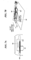
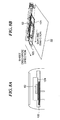
FIG. 7A is a schematic view of the post-processing apparatus as seen from the downstream side in the sheet discharge direction, with a sorting member inFIG. 3 positioned away from a recording sheet; -
FIG. 7B is a schematic view of the post-processing apparatus as seen from obliquely above, with the sorting member positioned away from the recording sheet; -
FIG. 8A is a schematic view of the post-processing apparatus as seen from the downstream side in the sheet discharge direction, with the sorting member in contact with the recording sheet; -
FIG. 8B is a schematic view of the post-processing apparatus as seen from obliquely above, with the sorting member in contact with the recording sheet; -
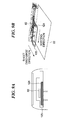
FIG. 9A is a schematic view of the post-processing apparatus as seen from the downstream side in the sheet discharge direction, with the sorting member moved in a sorting direction; -
FIG. 9B is a schematic view of the post-processing apparatus as seen from obliquely above, with the sorting member moved in the sorting direction; -
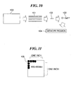
FIG. 10 is a schematic view showing a toner image formed in the image forming apparatus inFIG. 1 ; -
FIG. 11 is a schematic view showing a toner image formed in the image forming apparatus inFIG. 1 ; -
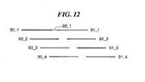
FIG. 12 is a view showing laser irradiation times (laser irradiation on/off timings) by a laser exposure unit inFIG. 1 for formation of respective color toner images and conveyance time intervals between first and second pages of recording sheets at the time of color image formation; -
FIG. 13 is a view showing laser irradiation times for a case where the recording sheet conveyance time interval is made longer than that shown inFIG. 12 ; -
FIG. 14 is a view showing laser irradiation times for a case where the recording sheet conveyance time interval is made longer than that shown inFIG. 13 ; -
FIG. 15 is a view showing recording sheet conveyance intervals respectively corresponding to three recording sheet conveyance time intervals shown inFIGS. 12 to 14 ; -
FIG. 16 is a view showing how toner use amounts used for image formation on respective pages of a first set are stored into a RAM shown inFIG. 6 ; -
FIG. 17 is a view showing how a break between sets is determined in a case that image formation is performed on plural sets of recording sheets; -
FIG. 18 is a flowchart showing the procedures of a recording sheet conveyance interval setting process implemented by the image forming apparatus inFIG. 6 ; and -
FIG. 19 is a flowchart showing the procedures of a recording sheet conveyance interval setting process according to a modification of the embodiment. - The present invention will now be described in detail below with reference to the drawings showing a preferred embodiment thereof.
-
FIG. 1 shows the construction of a full color printer as an image forming apparatus according to one embodiment of this invention. - The full color printer includes four image forming units. The four image forming units are
image forming units image forming units - The toner
image forming units - Around the
photosensitive drums primary charging devices devices transfer rollers drum cleaners - A
laser exposure unit 7 is disposed below theprimary charging devices 3a-3d and the developingdevices 4a-4d. - The developing
devices 4a-4d respectively contain yellow toner, cyan toner, magenta toner, and black toner. - The
photosensitive drums 2a-2d are each comprised of a negatively chargeable OPC photosensitive member having an aluminum drum member thereof formed with a photoconductive layer thereon, and are rotatably driven by a driving unit (not shown) at a predetermined process speed in a clockwise direction inFIG. 1 . - The
primary charging devices 3a-3d functioning as primary charging units uniformly charge surfaces of thephotosensitive drums 2a-2d at a predetermined negative potential with charging bias applied from a charging bias power source (not shown). - The developing
devices 4a-4d cause color toners to be adhered to electrostatic latent images formed on thephotosensitive drums 2a-2d, to thereby develop (visualize) the electrostatic latent images into toner images. - The
transfer rollers 5a-5d functioning as the primary transfer units are disposed for contact atprimary transfer parts 32a-32d with thephotosensitive drums 2a-2d via anintermediate transfer belt 8 functioning as a transfer unit. - The
drum cleaners 6a-6d have cleaning blades for removing residual toner remaining on thephotosensitive drums 2a-2d after the primary transfer. - The
intermediate transfer belt 8 is disposed on the upper surface side of thephotosensitive drums 2a-2d and stretched between a secondary transfer opposedroller 10 and atension roller 11. The secondary transfer opposedroller 10 is disposed for contact at asecondary transfer part 34 with asecondary transfer roller 12 via theintermediate transfer belt 8. Theintermediate transfer belt 8 is comprised of dielectric resin such as poly carbonate, poly ethylene terephthalate resin film, or poly vinylidene diffluoride resin film. - The
intermediate transfer belt 8 is disposed to be inclined such that aprimary transfer surface 8a thereof facing thephotosensitive drums 2a-2d is at a lower height level on itssecondary transfer roller 12 side than on another side thereof. - Specifically, the
intermediate transfer belt 8 is movable relative to thephotosensitive drums 2a-2d and inclined such that theprimary transfer surface 8a is at a lower height level on thesecondary transfer part 34 side than on the other side thereof. - More specifically, the angle of inclination is set at about 15 degrees. The
intermediate transfer belt 8 is stretched between the secondary transfer opposedroller 10 disposed on thesecondary transfer part 34 side for applying a driving force to theintermediate transfer belt 8 and thetension roller 11 for applying a tension force to theintermediate transfer belt 8, thetension roller 11 being disposed on the side opposite from theroller 10 with respect to theprimary transfer parts 32a-32d disposed therebetween. - The secondary transfer opposed
roller 10 is disposed for contact at thesecondary transfer part 34 with thesecond transfer roller 12 via theintermediate transfer belt 8. On the outside of the endlessintermediate transfer belt 8 and near thetension roller 11, there is disposed a belt cleaner (not shown) for removing and collecting residual toner remaining on the surface of theintermediate transfer belt 8. - On the side downstream of the
secondary transfer part 34 in the direction in which a recording sheet P is conveyed, a fixingunit 16 including a fixingroller 16a and a pressurizingroller 16b is disposed in a longitudinal path construction. - The
laser exposure unit 7 includes a laser emitting unit for emitting light in accordance with a time-series of electric digital image signals of given image information, and includes a polygon lens, a reflection mirror, and the like. Thelaser exposure unit 7 exposes thephotosensitive drums 2a-2d to light, thereby forming electrostatic latent images in respective colors, corresponding to the image information, on the surfaces of thephotosensitive drums 2a-2d which are charged by theprimary charging devices 3a-3d. - Next, an image forming operation of the image forming apparatus (full color printer) is described.
- When an image formation start signal is delivered, the
photosensitive drums 2a-2d of theimage forming units primary charging devices 3a-3d. - Next, the
laser exposure unit 7 irradiates laser light from the laser emitting unit in accordance with a color-separated image signal which is externally input. The laser light is irradiated onto thephotosensitive drums 2a-2d via the polygon lens, the reflection mirror, etc., whereby electrostatic latent images in respective colors are formed on thephotosensitive drums 2a-2d. - Then, by means of the developing
device 4a applied with a developing bias which is the same in polarity as the polarity of electrification (negative) of thephotosensitive drum 2a, yellow toner is adhered to the electrostatic image formed on thephotosensitive drum 2a, whereby the electrostatic latent image is visualized. - At the
primary transfer part 32a between thephotosensitive drum 2a and thetransfer roller 5a, the yellow toner image is primary-transferred onto theintermediate transfer belt 8, which is being driven, by means of thetransfer roller 5a applied with primary transfer bias (which is opposite (positive) in polarity to the toner). - The
intermediate transfer belt 8 to which the yellow toner image has been transferred is moved toward the tonerimage forming unit 1M. Then, a magenta toner image formed on thephotosensitive drum 2b in the tonerimage forming unit 1M is similarly transferred onto theintermediate transfer belt 8 at theprimary transfer part 32b such as to be superimposed on the yellow toner image on theintermediate transfer belt 8. - At this time, residual toner remaining on the
photosensitive drums 2a-2d is scraped off for recovery by means of cleaner blades or the like provided on thedrum cleaners 6a-6d. - Similarly, cyan and black toner images formed on the
photosensitive drums intermediate transfer belt 8 at theprimary transfer parts 32c, 32d. As a result, a full color toner image is formed on theintermediate transfer belt 8. - The recording sheet P is conveyed by
registration rollers 19 to thesecondary transfer part 34 between the secondary transfer opposedroller 10 and thesecondary transfer roller 12 in timing in which the tip end of the full color toner image on theintermediate transfer belt 8 is moved to thesecondary transfer part 34. The recording sheet P is fed via aconveyance path 18 from asheet feed cassette 17 or amanual feed tray 20. - By means of the
secondary transfer roller 12 applied with secondary transfer bias (which is opposite (positive) in polarity to the toner), the full color toner image is secondary-transferred onto the recording sheet P conveyed to thesecondary transfer part 34. - The recording sheet P on which the full color toner image has been formed is conveyed to the fixing
unit 16. The full color toner image is heated and pressurized at a fixing nippart 31 between the fixingroller 16a and the pressurizingroller 16b. As a result, the full color toner image is thermally fixed on a surface of the recording sheet P. Subsequently, the recording sheet P is caused by asheet discharge roller 21 to enter a post-processing apparatus, described later, and discharged onto asheet discharge tray 22 disposed on an upper surface of the main body of the apparatus. Whereupon, a series of image forming operations is completed. - Toner remaining on the
intermediate transfer belt 8 after the secondary transfer is removed for recovery by the belt cleaner. In the above, the image forming operation at the time of single-sided image formation has been described. -
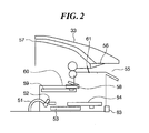
FIG. 2 shows the construction of thepost-processing apparatus 33 inFIG. 1 , andFIG. 3 shows thepost-processing apparatus 33 as seen from the side of a sheet discharge port thereof. - The
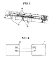
post-processing apparatus 33 for performing post-processing on a recording sheet P being discharged has asheet entry port 55 formed therein such that the recording sheet P conveyed by thesheet discharge roller 21 enters the interior of thepost-processing apparatus 33. Thepost-processing apparatus 33 has acommunication connector 63 having a transmission data terminal TXD and a reception data terminal RXD which are respectively connected to a reception data terminal RXD and a transmission data terminal TXD of a printer unit (shown byreference numeral 1 inFIG. 4 ). In a process of being fed with a recording sheet from theprinter unit 1, thepost-processing apparatus 33 carries out communication for synchronization as shown inFIG. 4 . The entry of the recording sheet through thesheet entry port 55 is detected by asensor 61. - Recording sheets P entered in succession through the
sheet entry port 55 are stacked on abundle tray 60. The recording sheets P stacked on thebundle tray 60 are each moved by a sortingmember 62 in a horizontal direction relative to a sheet discharge direction (sorting process). - As shown in
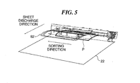
FIG. 5 , recording sheets P output from theprinter unit 1 are each moved in the sorting direction so as to be aligned with one another. After a predetermined number of recording sheets are stacked (a stacked state is shown by reference numeral 82), these recording sheets are stapled, where required, by a stapler (not shown), and then discharged by means of bundle dischargesliders 58. - Bundle-discharge-
slider pusher members 59 for driving thebundle discharge sliders 58 are drivingly coupled via coupling members (not shown) to sheet-restraint-pawl driving gears 54, wherebysheet restraint members 51 are driven. Thesheet restraint members 51 are operable to restrain discharged recording sheets, thereby suppressing recording sheets after subjected to thermal fixing from being curled. - Paper-
full detection flags 52 interconnected with thesheet restraint members 51 are adapted to turn on/off a sheet-full detectingsensor 53 and detect thesheet discharge tray 22 becoming full of sheets based on the thickness of discharged recording sheets P. When achangeover member 56 is switchingly operated, a recording sheet P is conveyed to aconveyance path 57 for sheet reverse in double-sided conveyance, described later. - Next, a description will be given of a double-sided image forming operation of the image forming apparatus of this embodiment.
- Portions of the double-sided image forming operation up to a full color toner image is thermally fixed onto a recording sheet P by the fixing
unit 16 are the same as relevant portions of the single-sided image forming operation. After completion of thermal fixing, the rotation of thesheet discharge roller 21 is stopped in a state in which most part of a recording sheet P is discharged onto thesheet discharge tray 22 by thesheet discharge roller 21. - At that time, the recording sheet P is stopped in a state where the rear end thereof reaches a reverse position. The
changeover member 56 of thepost-processing apparatus 33 is switchingly operated as previously described, and the recording sheet P in thepost-processing apparatus 33 is located within theconveyance path 57. - Next, the recording sheet P stopped from being conveyed by stopping the rotation of the
sheet discharge roller 21 is fed into a double-sided path having doublesided rollers 40, 41 (FIG. 1 ). To this end, thesheet discharge roller 21 is reversely rotated in a direction opposite to the direction of normal rotation. By the reverse rotation of thesheet discharge roller 21, the recording sheet P located at the reverse position is conveyed so as to reach the doublesided roller 40, with the rear end of the recording sheet P directed forward. - Thereafter, the recording sheet P is conveyed by the double
sided roller 40 toward the doublesided roller 41. Recording sheets P are conveyed in succession by the doublesided rollers registration rollers 19. During that time, an image formation start signal is generated. - As in the case of the single-sided image formation, each recording sheet P is moved by the
registration rollers 19 toward thesecondary transfer part 34 between the secondary transfer opposedroller 10 and thesecondary transfer roller 12 in timing in which the tip end of a full color toner image on theintermediate transfer belt 8 is moved toward thesecondary transfer part 34. - The toner image is transferred onto the recording sheet P in a state that the tip end of the toner image is made coincident with the tip end of the recording sheet P at the
secondary transfer part 34. Subsequently, the image on the recording sheet P is fixed by the fixingunit 16 as in the case of the single-sided image forming operation. Then, the recording sheet P is conveyed again by thesheet discharge roller 21, is caused to enter thepost-processing apparatus 33, and is finally discharged onto thesheet discharge tray 22. Whereupon, a series of image forming operations is completed. -
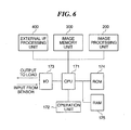
FIG. 6 shows control blocks of the image forming apparatus inFIG. 1 . - Referring to
FIG. 6 , theCPU 171 that implements the basic control of the image forming apparatus is connected via address buses and data buses to aROM 174 in which a control program is stored, a RAM (work RAM) 175 for temporarily storing calculation results, etc., and an input/output port (I/O) 173. - The
CPU 171 functions as a detection unit for detecting a toner use amount at toner image transfer by the transfer unit, and functions as a control unit for setting a plurality of recording sheet conveyance intervals and changing the conveyance interval. TheRAM 175 functions as a storage unit for storing toner use amounts used for respective pages. - Various loads (not shown) such as motors and clutches for driving the image forming apparatus and a sensor (not shown) for detecting the position of a recording sheet P are connected to the input/
output port 173. - The
CPU 171 carries out the image forming operations by controlling input and output via the input/output port 173 in accordance with the content stored in theROM 174. TheCPU 171 also controls a display unit and a key input unit of theoperation unit 172 connected to theCPU 171. - An operator operates the key input unit to instruct the
CPU 171 to switch an image forming operation mode and display. In response to the instruction, theCPU 171 displays the state of the image forming apparatus and the operation mode set by key input. - Connected to the
CPU 171 are an external I/F processing unit 400 for transmitting and receiving image data, process data, etc. to and from external equipment such as a PC, animage memory unit 300 for decompressing and temporarily storing images, and animage processing unit 200 for performing image processing based on line image data transferred from theimage memory unit 300. - Next, a description will be given of determination of toner fusion between recording sheets.
- Since recording sheets are pressed to each other by the sorting
member 62, there is a possibility that toner fusion takes place between the recording sheets. -
FIGS. 7A to 9B schematically show the operation of the sortingmember 62 inFIG. 3 .FIGS. 7A ,8A and9A schematically show thepost-processing apparatus 33 inFIG. 3 as seen from the downstream side in the sheet discharge direction.FIGS. 7B ,8B and9B schematically show thepost-processing apparatus 33 as seen from obliquely above. -
Reference numeral 124 denotes a discharged recording sheet, andreference numeral 125 denotes recording sheets waiting for being stapled. When therecording sheet 124 has been discharged from theprinter unit 1 to thepost-processing apparatus 33, the sortingmember 62 is moved downward from a position shown inFIG. 7A to a position shown inFIG. 8A , such as to be brought in contact with the recording sheet. - The sorting
member 62 made in contact with therecording sheet 124 is moved in the sorting direction, as shown inFIG. 9A , while remaining in contact with therecording sheet 124, whereby therecording sheet 124 is sorted. Recordingsheets 124 moved in succession in the sorting direction are stacked on therecording sheets 125 waiting for being stapled, until the number of stacked sheets reaches a staple number of sheets. - When the staple number of sheets is reached, the
stacked recording sheets 125 are stapled and then discharged. Toner fusion sometimes occurs when the sortingmember 62 is moved downward fromFIG. 7A to FIG. 8A and therecording sheet 124 is made in pressure contact with therecording sheets 125 waiting for being stapled. - If, in this state, toner fusion takes place between recording sheets, the discharged
recording sheet 124 cannot sufficiently be moved to the sorting position. As a result, alignment failure of recording sheets can occur at the time of sorting, and pages missing can occur at the time of stapling. - Next, a description will be given of the detection of toner density.
- As previously described with reference to
FIG. 1 , thelaser exposure unit 7 irradiates laser light from the laser emitting unit in accordance with an externally input color-separated image signal, and the laser light is irradiated via the polygon lens, the reflection mirror, etc. onto thephotosensitive drums 2a-2d on which electrostatic latent images in respective colors are thereby formed. -
FIG. 10 schematically shows a toner image formed in the image forming apparatus inFIG. 1 . - As shown in
FIG. 10 , atoner image 100 on each page is an aggregate of laser scannedlines 101, wherein each of thelines 101 is an aggregate ofdots 102 formed in accordance with the waveform of a laser signal. - In this embodiment, the apparatus has performance of forming 600 dots per inch in default. Electric potential 103 (toner transfer rate) at each
dot 102 of thetoner image 100 is controlled to a desired one of 16 levels from 0 to 15, whereby the densities in various parts of the electrostatic latent image are determined. - At the time of laser irradiation, a value obtained by integrating electric potentials at respective dots in a one-page image is stored into the
memory region 104, whereby toner density information on the one-page image can be obtained. In the following, with reference toFIG. 11 , toner fusion determination based on the toner density on a A3 size recording sheet (297 mm × 420 mm) will be described. -
FIG. 11 schematically shows a toner image formed in the image forming apparatus inFIG. 1 . - In a case that the printing density representing the printing performance of the image forming apparatus is 600 dots per inch (25.4 mm) as shown in
FIG. 11 , the number of dots in a one-page image is equal to (297/25.4) x 600 x (420/25.4) x 600. Electric potentials at all the dots in each one-page image are obtained and an integrated value of the electric potentials is calculated. If the integrated value is equal to or greater than a predetermined value, it is determined that a toner use amount used for the one-page image is large and hence there is a high possibility of occurrence of toner fusion between recording sheets due to the pressure contact by the sortingmember 62. - Next, a description will be given of control of a conveyance time interval for recording sheets P. The conveyance time interval control is implemented by the
CPU 171. -
FIGS. 12 to 14 show laser irradiation times (laser irradiation on/off timings) by thelaser exposure unit 7 inFIG. 1 for formation of respective color toner images and conveyance time intervals between first and second pages of recording sheets at the time of color image formation. The conveyance time interval becomes longer in the order ofFIGS. 12 ,13 and14 .FIG. 15 shows conveyance intervals 96_1 to 96_3 between adjacent ones of recording sheets 95_1 to 95_4. - In a case that, as shown in
FIG. 12 , a minimum value 92_1 is set as the conveyance time interval between the first page recording sheet and the second page recording sheet to maximize the productivity, the yellow toner image formation 91_1 for the second page is started before completion of the black toner image formation 90_4 for the first page. Hereinafter, the minimum conveyance time interval 92_1 will be referred to as the first conveyance time interval, which corresponds to the recording sheet conveyance interval 96_1 inFIG. 15 . -
FIG. 13 shows laser irradiation times (laser irradiation on/off timings) for the formation of respective color toner images at the time of color image formation in a case that a second conveyance time interval 92_2 is set as the recording sheet conveyance time interval (which corresponds to conveyance time). The second conveyance time interval 92_2 is longer than the first conveyance time interval 92_1. - In a case that the second conveyance time interval 92_2 is set as the recording sheet conveyance time interval, first toner image formation 91_5 for the second page is not started under the control of the
CPU 171 until completion of fourth toner image formation 90_8 for the first page. The second conveyance time interval 92_2 is longer than the first conveyance time interval 92_1 and corresponds to the recording sheet conveyance interval 96_2 inFIG. 15 . -
FIG. 14 shows laser irradiation times (laser irradiation on/off timings) for the formation of respective color toner images in a case where the third conveyance time interval 92_3 longer than the second conveyance time interval 92_2 is set as the recording sheet conveyance time interval. - In a case that the third conveyance time interval 92_3 is set as the recording sheet conveyance time interval, the recording sheet conveyance time interval is made wider to the extent that toner fusion does not occur between recording sheets P which are conveyed in succession. The third conveyance time interval 92_3 is longer than the first and second conveyance time intervals 92_1, 92_2 and corresponds to the recording sheet conveyance interval 96_3 in
FIG. 15 . - Next, a description will be given of recording sheet conveyance control implemented by the
CPU 171 inFIG. 6 to avoid occurrence of toner fusion. - In image formation on plural sets of recording sheets, the control content is different between when image formation is performed on a first set of recording sheets and when performed on a second and subsequent sets of recording sheets.
- At the time of image formation on the first set of recording sheets, the
CPU 171 starts the conveyance control to transfer recording sheets at the second conveyance time interval. Upon each completion of one-page image formation, theCPU 171 determines whether or not a toner use amount used for the image formation on the page concerned is equal to or greater than a predetermined amount. In the image formation on recording sheets conveyed at the second conveyance time interval, image formation on the next page is not started until completion of the image formation on the preceding page. - Therefore, when it is determined that the toner use amount used for the preceding page is large, the conveyance time interval between the preceding page and the next page can easily be widened to the third conveyance time interval. If it is determined that the toner use amount used for the preceding page is large, the
CPU 171 widens the conveyance time interval between the preceding page and the next page to the third conveyance time interval, and starts the image formation processing for the next page after the preceding page is sufficiently cooled. - If the toner use amount used for the preceding page is less than the predetermined amount, the
CPU 171 determines that toner fusion hardly takes place between the preceding page and the next page, and continues the operation of conveying recording sheets P at the second conveyance time interval. Even if the conveyance time interval has been once widened to the third conveyance time interval, when it is determined that toner fusion will not occur in subsequent pages, theCPU 171 puts the conveyance time interval back to the second conveyance time interval, and continues the operation of conveying recording sheets P. - During the image formation on the first set of recording sheets, the
CPU 171 stores toner use amounts 130_1 used for respective ones of all the pages (15 pages in the illustrated example) into a storage buffer (for example, theRAM 175 inFIG. 6 ), as shown inFIG. 16 (storage 131_1). - At the time of image formation on the second and subsequent sets of recording sheets, the
CPU 171 starts the conveyance control to transfer recording sheets at the third conveyance time interval. As for the first page of each set, post-processing on the preceding set is already completed and is output to thesheet discharge tray 22. Therefore, it is unnecessary to widen the conveyance interval between the preceding set and the next set. - Next, with reference to
FIGS. 16 and17 , a process for estimating toner use amounts for image formation on the second and subsequent sets will be described. This estimation process is implemented by theCPU 171. - In the processing for estimating a toner use amount for each page of the second or subsequent sets, the toner use amount 130_2 is used, which is stored in the
RAM 175 for the corresponding page of the first or preceding set. This is because that the toner use amount in image formation on each page of recording sheets is the same between respective sets. - The
CPU 171 is able to estimate a toner use amount for each page of the second set or the subsequent sets before completion of image formation on each page based on the toner use amount stored in theRAM 175 for the same page of the first set or the preceding set. If the estimated toner use amount is small, theCPU 171 is able to carry out the conveyance control not at the second conveyance time interval used for the first set but at the first conveyance time interval which is the shortest conveyance time interval. - The toner use amount used for the current page may be compared with the toner use amount stored in the
RAM 175 for the first page of the first set or the preceding set, and a break between sets (the first page of each sets) may be determined when both the toner user amounts are coincident with each other (seeFIG. 17 ). -
FIG. 18 shows in flowchart the procedures of a recording sheet conveyance interval setting process implemented by the image forming apparatus inFIG. 6 . This process is implemented by theCPU 171 inFIG. 6 . - In the conveyance interval setting process in
FIG. 18 , when a job is given, theCPU 171 determines whether or not the current operation mode is a post-processing mode in which tone fusion can sometimes take place. In this embodiment, it is determined whether or not the current mode is staple processing or sort processing to thereby determine whether or not the current operation mode is the post-processing mode (step S101). If the current operation mode is not stapling nor sorting, theCPU 171 determines that there is a low possibility of occurrence of toner fusion, and therefore sets the first recording sheet conveyance interval 96_1 as the recording sheet conveyance interval (step S110). - On the other hand, if it is determined at step S101 that the current operation mode is stapling or sorting, the
CPU 171 determines whether or not the current image forming operation is carried out for the second or subsequent sets (step S102). - If it is determined at step S102 that the current image forming operation is carried out for the first set, the
CPU 171 determines whether or not a toner use amount used for image formation on the preceding page is larger than the predetermined amount (S107). If the toner use amount is larger than the predetermined amount, the third conveyance interval 96_3 wider than the first and second conveyance intervals 96_1, 96_2 is set as the conveyance interval for the next page (step S108). If the toner use amount is not larger than the predetermined amount, theCPU 171 sets the second conveyance interval 96_2 as the conveyance interval for the next page (step S109). As for the first page, the flow proceeds from step S107 to step S109. Next, theCPU 171 stores the toner use amount used for the current page into the RAM 175 (step S105). Whereupon, the conveyance interval setting process inFIG. 18 is completed. - If it is determined in step S102 that the current image forming operation is implemented for the second or subsequent set, the
CPU 171 determines whether or not the toner use amount used for the image formation on the same page of the preceding set and stored in step S105 into theRAM 175 is larger than the predetermined amount (step S103) . - If the toner use amount used for the same page of the preceding set is larger than the predetermined amount, the
CPU 171 sets the third conveyance interval 96_3 as the recording sheet conveyance interval (step S104). If the toner use amount is less than the predetermined amount, the first conveyance interval 96_1 narrower than the third conveyance interval 96_3 is set as the recording sheet conveyance interval (step S106). - In this embodiment, for the first set, the
CPU 171 sets the second or third conveyance interval based on the toner use amount, as described above. As a result, the image formation on recording sheets of the first set is completed before start of image formation on recording sheets of the second set. For the second and subsequent sets, theCPU 171 sets the first or third conveyance interval based on the toner use amount stored in theRAM 175 for the preceding set. - It should be noted that only the toner use amounts used for respective pages of the first set may be stored. In that case, as shown in
FIG. 19 , the toner use amount for the same page of the first set is referred to in step S103. In step S104 or S106, the recording sheet conveyance interval is set. Thereafter, the conveyance interval setting process inFIG. 18 is completed, without toner use amount being stored. - The changeover between the first, second, and third conveyance intervals by the
CPU 171 is also applicable to a case where post-processing other than stapling and sorting is carried out on recording sheets P by thepost-processing apparatus 33. - While the present invention has been described with reference to an exemplary embodiment, it is to be understood that the invention is not limited to the disclosed exemplary embodiment. The scope of the following claims is to be accorded the broadest interpretation so as to encompass all such modifications and equivalent structures and functions.
Claims (7)
- An image forming apparatus for carrying out plural identical sets of image formation on recording sheets comprising:image forming means (2-8) adapted to form, based on image data of respective pages of the plural identical sets, toner images on the recording sheets for the respective pages;fixing means (16) adapted to thermally fix the toner images onto the recording sheets for the respective pages;control means (171) adapted to control each recording sheet conveyance interval between the recording sheets,characterized in that said control means further comprises,detection means adapted to detect the respective toner use amounts of each of the toner images in the image formation on a first set of the plural sets; andstorage means (175) adapted to store each of said detected toner use amounts; andimage formation of a second set of whereby said identical plural sets following the first set, said control means is adapted to control each recording sheet conveyance interval based on said stored toner use amount of the like toner image page of the first set.
- The image forming apparatus according to claim 1, wherein said control means (171) is adapted to determine whether or not a toner use amount used for a predetermined page of one of the plural sets is more than a predetermined value based on the each toner use amount detected by said detection unit to set a following recording sheet conveyance interval between the predetermined page and a page next thereto, so that the following recording sheet conveyance interval is controlled to be wider when the toner use amount used for the predetermined page is determined to be more than the predetermined value than when not.
- The image forming apparatus according to claim 2, wherein in the image formation on the first set said control means (171) is adapted to set the following recording sheet conveyance interval to a first recording sheet conveyance interval when the toner use amount used for the predetermined page is determined to be more than the predetermined value , and is further adapted to set the following recording sheet conveyance interval to a second recording sheet conveyance interval when the toner use amount used for the predetermined page is determined not to be more than the predetermined value , wherein the first recording sheet conveyance interval is wider than the second recording conveyance interval.
- The image forming apparatus according to claim 3, wherein in the image formation on the second set , said control means (171) is adapted to set the following recording sheet conveyance interval to a third recording sheet conveyance interval when the toner use amount used for the predetermined page is determined not to be less than the predetermined value, and is further adapted to set the following recording sheet conveyance interval to a fourth recording sheet conveyance interval when the toner use amount used for the predetermined page is determined to be less than the predetermined value , wherein the third recording sheet conveyance interval is wider than the fourth recording conveyance interval.
- The image forming apparatus according to claim 4, wherein the first recording sheet conveyance interval is equal to the third recording sheet conveyance interval.
- The image forming apparatus according to claim 1, including a post-processing apparatus (33) adapted to carry out post-processing on recording sheets,
wherein said control means (171) is adapted to control the each recording sheet conveyance in accordance with the each detected toner use amount in a case where particular post-processing is carried out on one of the recording sheets for the respective pages. - The image forming apparatus according to claim 6, wherein the particular post-processing includes at least one of staple processing and sort processing.
Applications Claiming Priority (1)
| Application Number | Priority Date | Filing Date | Title |
|---|---|---|---|
| JP2007197494A JP5100238B2 (en) | 2007-07-30 | 2007-07-30 | Image forming apparatus |
Publications (2)
| Publication Number | Publication Date |
|---|---|
| EP2028553A1 EP2028553A1 (en) | 2009-02-25 |
| EP2028553B1 true EP2028553B1 (en) | 2010-11-17 |
Family
ID=40225293
Family Applications (1)
| Application Number | Title | Priority Date | Filing Date |
|---|---|---|---|
| EP08159438A Active EP2028553B1 (en) | 2007-07-30 | 2008-07-01 | Image forming apparatus |
Country Status (5)
| Country | Link |
|---|---|
| US (1) | US8032044B2 (en) |
| EP (1) | EP2028553B1 (en) |
| JP (1) | JP5100238B2 (en) |
| CN (2) | CN102253618B (en) |
| DE (1) | DE602008003493D1 (en) |
Families Citing this family (7)
| Publication number | Priority date | Publication date | Assignee | Title |
|---|---|---|---|---|
| JP5538669B2 (en) * | 2007-08-31 | 2014-07-02 | キヤノン株式会社 | Image forming apparatus, image forming apparatus control method, storage medium, and program |
| MX2011008282A (en) | 2009-02-13 | 2011-08-24 | Panasonic Corp | Communication device and communication method. |
| JP2012042800A (en) | 2010-08-20 | 2012-03-01 | Canon Inc | Image forming apparatus |
| JP5919865B2 (en) * | 2012-02-15 | 2016-05-18 | ブラザー工業株式会社 | Image forming apparatus |
| JP6234126B2 (en) * | 2013-09-10 | 2017-11-22 | キヤノン株式会社 | Image forming apparatus |
| JP6602049B2 (en) * | 2014-06-17 | 2019-11-06 | キヤノン株式会社 | Image forming apparatus |
| JP7039246B2 (en) * | 2017-10-18 | 2022-03-22 | キヤノン株式会社 | Image forming device |
Family Cites Families (15)
| Publication number | Priority date | Publication date | Assignee | Title |
|---|---|---|---|---|
| JPH0784483A (en) * | 1993-09-14 | 1995-03-31 | Canon Inc | Image forming device |
| JP2993411B2 (en) * | 1995-10-19 | 1999-12-20 | 富士ゼロックス株式会社 | Image forming device |
| JPH1097142A (en) * | 1996-09-24 | 1998-04-14 | Ricoh Co Ltd | Image forming device |
| JP2000122506A (en) * | 1998-10-09 | 2000-04-28 | Konica Corp | Copying device |
| JP2001080163A (en) * | 1999-09-10 | 2001-03-27 | Hitachi Koki Co Ltd | Printing apparatus |
| JP4356306B2 (en) | 2001-12-20 | 2009-11-04 | 富士ゼロックス株式会社 | Image forming apparatus |
| US6868240B2 (en) * | 2002-03-15 | 2005-03-15 | Kyocera Corporation | Method for developing in hybrid developing apparatus |
| US6829448B2 (en) * | 2002-03-26 | 2004-12-07 | Kyocera Corporation | Image forming apparatus and image forming method |
| JP4115206B2 (en) * | 2002-08-28 | 2008-07-09 | キヤノン株式会社 | Image forming apparatus |
| JP2006150798A (en) | 2004-11-30 | 2006-06-15 | Canon Inc | Inkjet recording device |
| JP2006243498A (en) * | 2005-03-04 | 2006-09-14 | Fuji Xerox Co Ltd | Image forming apparatus |
| JP4500712B2 (en) * | 2005-03-14 | 2010-07-14 | キヤノン株式会社 | Image forming apparatus and image forming control method |
| JP2006349755A (en) | 2005-06-13 | 2006-12-28 | Kyocera Mita Corp | Image forming apparatus |
| JP2007153465A (en) * | 2005-11-30 | 2007-06-21 | Canon Finetech Inc | Sheet processing device and image forming device provided with same |
| JP5020733B2 (en) * | 2007-07-27 | 2012-09-05 | キヤノン株式会社 | Image forming apparatus |
-
2007
- 2007-07-30 JP JP2007197494A patent/JP5100238B2/en active Active
-
2008
- 2008-07-01 EP EP08159438A patent/EP2028553B1/en active Active
- 2008-07-01 DE DE602008003493T patent/DE602008003493D1/en active Active
- 2008-07-29 US US12/182,052 patent/US8032044B2/en not_active Expired - Fee Related
- 2008-07-30 CN CN201110225014.XA patent/CN102253618B/en not_active Expired - Fee Related
- 2008-07-30 CN CN2008101351067A patent/CN101359197B/en active Active
Also Published As
| Publication number | Publication date |
|---|---|
| CN102253618B (en) | 2016-01-20 |
| DE602008003493D1 (en) | 2010-12-30 |
| JP2009031652A (en) | 2009-02-12 |
| US8032044B2 (en) | 2011-10-04 |
| JP5100238B2 (en) | 2012-12-19 |
| CN102253618A (en) | 2011-11-23 |
| EP2028553A1 (en) | 2009-02-25 |
| US20090035005A1 (en) | 2009-02-05 |
| CN101359197B (en) | 2011-09-14 |
| CN101359197A (en) | 2009-02-04 |
Similar Documents
| Publication | Publication Date | Title |
|---|---|---|
| EP2028553B1 (en) | Image forming apparatus | |
| JP4798470B2 (en) | Printing device | |
| EP1764660A1 (en) | Image forming apparatus capable of effectively adjusting an image registration | |
| JP2007072294A (en) | Image forming apparatus and method for controlling the image forming apparatus | |
| US20050220465A1 (en) | Image forming apparatus | |
| EP2019341B1 (en) | Image forming apparatus | |
| JP5109457B2 (en) | Image forming apparatus | |
| EP2023210B1 (en) | Image forming apparatus | |
| JP6805707B2 (en) | Image forming device and image defect judgment program | |
| US6985679B2 (en) | Image forming apparatus with cleaning operation for special sheets | |
| JPH11208979A (en) | Image forming device | |
| US8346142B2 (en) | Image forming apparatus configured to eject air toward a gap between the top end of a sheet having passed through a nip portion and the circumference of a fixing rotating member of the nip portion | |
| JP2006221005A (en) | Image forming apparatus | |
| CN102739899B (en) | Image forming apparatus | |
| JP2007310365A (en) | Method for controlling image forming apparatus | |
| JP2006251619A (en) | Image forming apparatus and image forming method | |
| JP5332154B2 (en) | Image forming apparatus | |
| JP2005164922A (en) | Image forming apparatus | |
| JP2006139109A (en) | Image forming apparatus | |
| JP6746878B2 (en) | Charge control device, image forming apparatus, and image forming system | |
| JP2004314388A (en) | Image forming apparatus | |
| JP2020142882A (en) | Sheet discharger and image forming system | |
| JP2009058689A (en) | Image forming apparatus | |
| JP2008083470A (en) | Image forming apparatus and program to be executed by computer of image forming apparatus | |
| JP2006091728A (en) | Image forming apparatus |
Legal Events
| Date | Code | Title | Description |
|---|---|---|---|
| PUAI | Public reference made under article 153(3) epc to a published international application that has entered the european phase |
Free format text: ORIGINAL CODE: 0009012 |
|
| AK | Designated contracting states |
Kind code of ref document: A1 Designated state(s): AT BE BG CH CY CZ DE DK EE ES FI FR GB GR HR HU IE IS IT LI LT LU LV MC MT NL NO PL PT RO SE SI SK TR |
|
| AX | Request for extension of the european patent |
Extension state: AL BA MK RS |
|
| 17Q | First examination report despatched |
Effective date: 20090918 |
|
| AKX | Designation fees paid |
Designated state(s): DE FR GB IT |
|
| 17P | Request for examination filed |
Effective date: 20090825 |
|
| GRAP | Despatch of communication of intention to grant a patent |
Free format text: ORIGINAL CODE: EPIDOSNIGR1 |
|
| GRAS | Grant fee paid |
Free format text: ORIGINAL CODE: EPIDOSNIGR3 |
|
| GRAA | (expected) grant |
Free format text: ORIGINAL CODE: 0009210 |
|
| AK | Designated contracting states |
Kind code of ref document: B1 Designated state(s): DE FR GB IT |
|
| REG | Reference to a national code |
Ref country code: GB Ref legal event code: FG4D |
|
| REF | Corresponds to: |
Ref document number: 602008003493 Country of ref document: DE Date of ref document: 20101230 Kind code of ref document: P |
|
| PLBE | No opposition filed within time limit |
Free format text: ORIGINAL CODE: 0009261 |
|
| STAA | Information on the status of an ep patent application or granted ep patent |
Free format text: STATUS: NO OPPOSITION FILED WITHIN TIME LIMIT |
|
| 26N | No opposition filed |
Effective date: 20110818 |
|
| REG | Reference to a national code |
Ref country code: DE Ref legal event code: R097 Ref document number: 602008003493 Country of ref document: DE Effective date: 20110818 |
|
| REG | Reference to a national code |
Ref country code: FR Ref legal event code: PLFP Year of fee payment: 9 |
|
| REG | Reference to a national code |
Ref country code: FR Ref legal event code: PLFP Year of fee payment: 10 |
|
| REG | Reference to a national code |
Ref country code: FR Ref legal event code: PLFP Year of fee payment: 11 |
|
| PGFP | Annual fee paid to national office [announced via postgrant information from national office to epo] |
Ref country code: IT Payment date: 20220621 Year of fee payment: 15 Ref country code: GB Payment date: 20220621 Year of fee payment: 15 |
|
| PGFP | Annual fee paid to national office [announced via postgrant information from national office to epo] |
Ref country code: FR Payment date: 20220621 Year of fee payment: 15 |
|
| PGFP | Annual fee paid to national office [announced via postgrant information from national office to epo] |
Ref country code: DE Payment date: 20220621 Year of fee payment: 15 |
|
| REG | Reference to a national code |
Ref country code: DE Ref legal event code: R119 Ref document number: 602008003493 Country of ref document: DE |
|
| GBPC | Gb: european patent ceased through non-payment of renewal fee |
Effective date: 20230701 |