EP2028514A1 - Optical fiber core and process for producing the same - Google Patents
Optical fiber core and process for producing the same Download PDFInfo
- Publication number
- EP2028514A1 EP2028514A1 EP07745024A EP07745024A EP2028514A1 EP 2028514 A1 EP2028514 A1 EP 2028514A1 EP 07745024 A EP07745024 A EP 07745024A EP 07745024 A EP07745024 A EP 07745024A EP 2028514 A1 EP2028514 A1 EP 2028514A1
- Authority
- EP
- European Patent Office
- Prior art keywords
- optical fiber
- coating layer
- secondary coating
- glass
- pistoning
- Prior art date
- Legal status (The legal status is an assumption and is not a legal conclusion. Google has not performed a legal analysis and makes no representation as to the accuracy of the status listed.)
- Granted
Links
Images

Classifications
-
- G—PHYSICS
- G02—OPTICS
- G02B—OPTICAL ELEMENTS, SYSTEMS OR APPARATUS
- G02B6/00—Light guides; Structural details of arrangements comprising light guides and other optical elements, e.g. couplings
- G02B6/44—Mechanical structures for providing tensile strength and external protection for fibres, e.g. optical transmission cables
- G02B6/4401—Optical cables
- G02B6/4429—Means specially adapted for strengthening or protecting the cables
- G02B6/443—Protective covering
-
- C—CHEMISTRY; METALLURGY
- C03—GLASS; MINERAL OR SLAG WOOL
- C03C—CHEMICAL COMPOSITION OF GLASSES, GLAZES OR VITREOUS ENAMELS; SURFACE TREATMENT OF GLASS; SURFACE TREATMENT OF FIBRES OR FILAMENTS MADE FROM GLASS, MINERALS OR SLAGS; JOINING GLASS TO GLASS OR OTHER MATERIALS
- C03C25/00—Surface treatment of fibres or filaments made from glass, minerals or slags
- C03C25/10—Coating
- C03C25/104—Coating to obtain optical fibres
- C03C25/1065—Multiple coatings
-
- G—PHYSICS
- G02—OPTICS
- G02B—OPTICAL ELEMENTS, SYSTEMS OR APPARATUS
- G02B6/00—Light guides; Structural details of arrangements comprising light guides and other optical elements, e.g. couplings
- G02B6/02—Optical fibres with cladding with or without a coating
- G02B6/02395—Glass optical fibre with a protective coating, e.g. two layer polymer coating deposited directly on a silica cladding surface during fibre manufacture
Definitions
- the present invention relates to a buffered optical fiber, and more particularly, to a buffered optical fiber with an improved pistoning characteristic and a manufacturing method thereof.
- a buffered optical fiber when manufacturing a buffered optical fiber, at least two coating layers made of silicon-based thermosetting type resin or UV curing resin are applied to the circumference of a glass optical fiber having a diameter of approximately 125 ⁇ m to form an optical fiber and this circumference is coated with polyvinyl chloride resin, nylon resin, polyester elastomer resin or the like to form a buffered optical fiber. Though it depends on the use, optical fibers having an outer diameter of approximately 250 ⁇ m and approximately 400 ⁇ m are used most.
- a buffered optical fiber One of important characteristics of a buffered optical fiber is a pistoning characteristic.
- “Pistoning” means a phenomenon that a glass optical fiber inside the buffered optical fiber protrudes from an end face of coating and when the pistoning characteristic is poor, that is, when the amount of pistoning of the glass optical fiber from the end face of coating is large, there are problems with connections such as occurrence of breaking of the glass optical fiber in the connector.
- a buffered optical fiber used for a laser module or the like in particular is required to have an extremely small amount of glass pistoning.
- Patent Document 1 Japanese Patent Application Laid-Open No. 2004-252388
- Patent Document 2 Japanese Patent Application Laid-Open No. 2005-189390
- Patent Documents 1, 2 when the techniques disclosed in Patent Documents 1, 2 are used, it is difficult to sufficiently suppress the pistoning characteristic of the glass fiber without improving the composition of resin (e.g., suppressing the amount of pistoning to 0.5 mm or less) and there is a problem with the aspects of cost and time incurred in manufacturing.
- the present invention has been implemented in view of the above described problems and it is an object of the present invention to provide a buffered optical fiber having an improved pistoning characteristic compared to the conventional one. Furthermore, it is another object of the present invention to provide a method of manufacturing a buffered optical fiber capable of easily obtaining a buffered optical fiber with an excellent pistoning characteristic.
- the buffered optical fiber of the present invention is composed of an optical fiber with a primary coating layer and a secondary coating layer provided on a circumference of a glass optical fiber and a tertiary coating layer having thermoplastic polyester elastomer as the main ingredient provided on a circumference of the optical fiber, characterized in that an outer diameter of the primary coating layer is 180 to 200 ⁇ m, an outer diameter of the secondary coating layer is 350 to 450 ⁇ m and the product of a thickness of the secondary coating layer of the optical fiber and a force of pulling out the glass optical fiber from the optical fiber is 720N/mm ⁇ m or more. Furthermore, the thickness of the secondary coating layer may be configured to be 85 ⁇ m or more.
- the method of manufacturing a buffered optical fiber of the present invention provides an optical fiber with a primary coating layer and a secondary coating layer on a circumference of a glass optical fiber and a tertiary coating layer having thermoplastic polyester elastomer as the main ingredient provided on a circumference of the optical fiber and is characterized in that the thickness of the secondary coating layer is determined such that an outer diameter of the primary coating layer is 180 to 200 ⁇ m, an outer diameter of the secondary coating layer is 350 to 450 ⁇ m and the product of the thickness of the secondary coating layer and a force of pulling out the glass optical fiber from the optical fiber is 720N/mm ⁇ m or more. Furthermore, the thickness of the secondary coating layer may be 85 ⁇ m or more.
- the present invention by designing the thickness of the secondary coating layer according to the characteristic of resin, it is possible to easily obtain a buffered optical fiber having a satisfactory pistoning characteristic. Therefore, compared to the conventional buffered optical fiber manufactured by improving the composition of resin to improve the pistoning characteristic, the present invention is more advantageous in the aspects of cost and time incurred in manufacturing.
- FIG. 1 is a cross-sectional view of a buffered optical fiber 10 according to an embodiment of the present invention.
- reference numeral 11 denotes a glass optical fiber
- 12 denotes a primary coating layer applied to the circumference thereof
- 13 denotes a secondary coating layer applied to the circumference of the primary coating layer 12.
- the glass optical fiber 11 coated with the primary coating layer 12 and secondary coating layer 13 is called an "optical fiber.”
- a tertiary coating layer 14 having thermoplastic polyester elastomer as the main ingredient is provided on the circumference of the optical fiber and the optical fiber coated with the tertiary coating layer is called an "buffered optical fiber.”
- UV curing resin or the like is used for both the primary coating layer 12 and secondary coating layer 13 and this buffered optical fiber 10 is actually formed by sequentially applying these layers to the circumference of the drawn glass optical fiber 11.
- UV curing resin especially urethane acrylate based UV curing resin is preferably used. The reason is that this resin has excellent flexibility and a satisfactory buffering function can be expected for a bare glass surface.
- the present invention uses a soft primary coating layer 12 with low Young's modulus which directly contacts the glass surface and uses a relatively hard secondary coating layer 13 outside of it with high Young's modulus.
- the mechanical strength of this optical fiber is secured in this way. Adjustments to Young's modulus for both layers are made by mixing or adding additives or fillers or the like.
- the tertiary coating layer 14 is generally formed using thermoplastic resin so that its diameter is approximately 0.9 mm.
- This thermoplastic resin is not particularly limited, but it is preferable to use thermoplastic polyester elastomer having a tensile elastic modulus of 300 to 700 MPa. This large tensile elastic modulus provides sufficient mechanical strength required for a buffered optical fiber.
- the outer diameter of the primary coating layer is preferably 180 ⁇ m or more and the thickness of the secondary coating layer is preferably 85 ⁇ m or more.
- a primary coating layer was formed on the circumference of a glass optical fiber having an outer diameter (diameter) of approximately f125 ⁇ m, a secondary coating layer was further formed on the circumference thereof and an optical fiber was thereby manufactured.
- the outer diameter of the primary coating layer was set to 190 to 200 ⁇ m and the outer diameter of the secondary coating layer was set to 350 to 450 ⁇ m.
- urethane acrylate based UV curing resin was used for both, and Young's modulus and the glass pulling out force to pull out the glass optical fiber of the primary coating layer and secondary coating layer were adjusted by mixing additives and fillers such as monomer, oligomer, silane coupling agent.
- a tertiary coating layer was formed on the circumference of the optical fiber obtained to form a buffered optical fiber.
- resin material of the tertiary coating layer thermoplastic polyester elastomer having a tensile elastic modulus of 300 MPa was used and the outer diameter (diameter) thereof was set to 0.9 mm. The results obtained are shown in Table 1.
- Young's modulus of the primary coating layer was calculated using an ISM (In Situ Modulus) testing method. More specifically, as shown in FIG. 2 , a sample was prepared by leaving only the coating of 10 mm from one end and removing the coating of the rest so as to expose the glass optical fiber and the coated part of the sample was fixed using an adhesive or the like. A force was gradually added so as to pull out the glass optical fiber toward the unfixed end at a temperature of 23°C and displacement of the glass optical fiber was measured.
- ISM In situ Modulus
- Young's modulus of the secondary coating layer was calculated as follows. As shown in FIG. 3 , a coated part along a slice line 22 (line along the interface between a glass optical fiber 23 and a primary coating layer 24) was obtained from an optical fiber 21 as a slice 26 shown in FIG. 3(b) .
- Reference numeral 25 denotes a secondary coating layer.
- This slice 26 was subjected to a tensile test under conditions with a temperature of 23°C, pulling speed of 1 mm/min and distance between reference lines of 25 mm and Young's modulus was calculated from the tensile strength when the distance between reference lines was distorted by 2.5%. As the cross-sectional area of the slice 26, a value actually measured using a microscope was used.
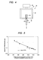
- the force of pulling the glass optical fiber was calculated in a condition of the optical fiber using the method in FIG. 4 .
- Sandpaper 32 was adhered to the tip of a sample optical fiber 31 and using this as a stopper, the sample optical fiber 31 was passed through a hole 36 formed in a lower horizontal base 35 of a hanging frame 34 of a glass pulling out tool 33 from above.
- a notch 31a was formed in the circumference of the optical fiber 31 on the bottom side of the sandpaper 32, and the sample optical fiber 31 in this condition was pull at a pulling speed of 5.0 mm/min. It was then pulled out by an arbitrary length and maximum stress then was measured using a sensor (load cell) 38 provided for an upper horizontal base 37 of the hanging frame 34.
- the pistoning characteristic was obtained from the amount of pistoning of the glass optical fiber inside. More specifically, the amount of pistoning was measured after 500 cycles, each cycle consisting of keeping a sample buffered optical fiber of 1.0 m long at -40°C for 30 minutes and then keeping it at 85°C for 30 minutes.
- a buffered optical fiber was prepared as follows and the pistoning characteristic thereof was examined.
- a primary coating layer was formed on the circumference of a glass optical fiber having an outer diameter (diameter) of approximately f125 ⁇ m
- a secondary coating layer was further formed on the circumference thereof and the circumference was then overcoated with the same resin material as that of the secondary coating layer to manufacture an optical fiber.
- the outer diameter of the primary coating layer was set to 190 to 200 ⁇ m
- the outer diameter of the secondary coating layer was set to approximately 250 ⁇ m
- the outer diameter after the overcoating was set to 350 to 450 ⁇ m.
- urethane acrylate based UV curing resin As the resin material of the primary coating layer, secondary coating layer and overcoat, urethane acrylate based UV curing resin was used for all, and Young's modulus and glass pulling out force to pull the glass optical fiber of the primary coating layer and secondary coating layer were adjusted by mixing additives and fillers such as monomer, oligomer, silane coupling agent.
- a tertiary coating layer was formed on the circumference of the optical fiber obtained to form a buffered optical fiber.
- resin material of the tertiary coating layer thermoplastic polyester elastomer having a tensile elastic modulus of 300 MPa was used and the outer diameter (diameter) thereof was set to 0.9 mm.
- FIG. 5 is a graph showing a relationship between the thickness of the secondary coating layer ⁇ force of pulling out the glass optical fiber and the amount of pistoning obtained in Example 1 and Example 2.
- “•” denotes the data in Example 1
- “ ⁇ ” denotes the data in Example 2.
- the outer diameter (diameter) of the buffered optical fiber was assumed to be 0.9 mm, but the present invention is not limited to this.
- the conventional buffered optical fiber has improved the composition of resin for improving the pistoning, incurring cost and time, but using the present invention to cause the thickness of the secondary coating layer to change according to the characteristic of resin makes it possible to easily manufacture a buffered optical fiber having a good pistoning characteristic.
Landscapes
- Physics & Mathematics (AREA)
- Chemical & Material Sciences (AREA)
- General Physics & Mathematics (AREA)
- Optics & Photonics (AREA)
- Life Sciences & Earth Sciences (AREA)
- Engineering & Computer Science (AREA)
- General Life Sciences & Earth Sciences (AREA)
- Chemical Kinetics & Catalysis (AREA)
- General Chemical & Material Sciences (AREA)
- Geochemistry & Mineralogy (AREA)
- Materials Engineering (AREA)
- Organic Chemistry (AREA)
- Optical Fibers, Optical Fiber Cores, And Optical Fiber Bundles (AREA)
- Surface Treatment Of Glass Fibres Or Filaments (AREA)
Abstract
Description
- The present invention relates to a buffered optical fiber, and more particularly, to a buffered optical fiber with an improved pistoning characteristic and a manufacturing method thereof.
- Conventionally, when manufacturing a buffered optical fiber, at least two coating layers made of silicon-based thermosetting type resin or UV curing resin are applied to the circumference of a glass optical fiber having a diameter of approximately 125 µm to form an optical fiber and this circumference is coated with polyvinyl chloride resin, nylon resin, polyester elastomer resin or the like to form a buffered optical fiber. Though it depends on the use, optical fibers having an outer diameter of approximately 250 µm and approximately 400 µm are used most.
- One of important characteristics of a buffered optical fiber is a pistoning characteristic. "Pistoning" means a phenomenon that a glass optical fiber inside the buffered optical fiber protrudes from an end face of coating and when the pistoning characteristic is poor, that is, when the amount of pistoning of the glass optical fiber from the end face of coating is large, there are problems with connections such as occurrence of breaking of the glass optical fiber in the connector. A buffered optical fiber used for a laser module or the like in particular is required to have an extremely small amount of glass pistoning.
- As a buffered optical fiber with an improved pistoning characteristic, there are proposals such as one characterized in that Young's modulus of secondary coating is 250 MPa or less and primary stripping force of the optical fiber is 100 g/10 mm to 700 g/10 mm (see Patent Document 1) and another one characterized in that a primary coating layer has a two-layer structure of a buffering layer having low Young's modulus and a protective layer having high Young's modulus, Young's modulus of the buffering layer of the primary coating layer is 0.8 MPa or less, breaking strength is 3.0 MPa or more and glass pulling out force is 0.4 to 1.5 N/mm (see Patent Document 2).
Patent Document 1: Japanese Patent Application Laid-Open No.2004-252388
Patent Document 2: Japanese Patent Application Laid-Open No.2005-189390 - However, when the techniques disclosed in
Patent Documents 1, 2 are used, it is difficult to sufficiently suppress the pistoning characteristic of the glass fiber without improving the composition of resin (e.g., suppressing the amount of pistoning to 0.5 mm or less) and there is a problem with the aspects of cost and time incurred in manufacturing. - The present invention has been implemented in view of the above described problems and it is an object of the present invention to provide a buffered optical fiber having an improved pistoning characteristic compared to the conventional one. Furthermore, it is another object of the present invention to provide a method of manufacturing a buffered optical fiber capable of easily obtaining a buffered optical fiber with an excellent pistoning characteristic.
- The buffered optical fiber of the present invention is composed of an optical fiber with a primary coating layer and a secondary coating layer provided on a circumference of a glass optical fiber and a tertiary coating layer having thermoplastic polyester elastomer as the main ingredient provided on a circumference of the optical fiber, characterized in that an outer diameter of the primary coating layer is 180 to 200 µm, an outer diameter of the secondary coating layer is 350 to 450 µm and the product of a thickness of the secondary coating layer of the optical fiber and a force of pulling out the glass optical fiber from the optical fiber is 720N/mm·µm or more. Furthermore, the thickness of the secondary coating layer may be configured to be 85 µm or more.
- Furthermore, the method of manufacturing a buffered optical fiber of the present invention provides an optical fiber with a primary coating layer and a secondary coating layer on a circumference of a glass optical fiber and a tertiary coating layer having thermoplastic polyester elastomer as the main ingredient provided on a circumference of the optical fiber and is characterized in that the thickness of the secondary coating layer is determined such that an outer diameter of the primary coating layer is 180 to 200 µm, an outer diameter of the secondary coating layer is 350 to 450 µm and the product of the thickness of the secondary coating layer and a force of pulling out the glass optical fiber from the optical fiber is 720N/mm·µm or more. Furthermore, the thickness of the secondary coating layer may be 85 µm or more.
- According to the present invention, by designing the thickness of the secondary coating layer according to the characteristic of resin, it is possible to easily obtain a buffered optical fiber having a satisfactory pistoning characteristic. Therefore, compared to the conventional buffered optical fiber manufactured by improving the composition of resin to improve the pistoning characteristic, the present invention is more advantageous in the aspects of cost and time incurred in manufacturing.
-
-
FIG. 1 is a traverse cross-sectional view of a buffered optical fiber according to an embodiment of the present invention; -
FIG. 2 is a diagram showing an ISM testing method for measuring Young's modulus of a primary coating layer; -
FIG. 3 is a diagram showing a process of obtaining a slice of the optical fiber used for a tensile test to measure Young's modulus of a secondary coating layer; -
FIG. 4 is a schematic diagram illustrating a method of measuring a glass pulling out force; and -
FIG. 5 is a graph showing a relationship between the thickness of the secondary coating layer × the pulling out force and the amount of pistoning. -
FIG. 1 is a cross-sectional view of a bufferedoptical fiber 10 according to an embodiment of the present invention. InFIG. 1 ,reference numeral 11 denotes a glass optical fiber, 12 denotes a primary coating layer applied to the circumference thereof and 13 denotes a secondary coating layer applied to the circumference of theprimary coating layer 12. Here, the glassoptical fiber 11 coated with theprimary coating layer 12 andsecondary coating layer 13 is called an "optical fiber." Furthermore, atertiary coating layer 14 having thermoplastic polyester elastomer as the main ingredient is provided on the circumference of the optical fiber and the optical fiber coated with the tertiary coating layer is called an "buffered optical fiber." - UV curing resin or the like is used for both the
primary coating layer 12 andsecondary coating layer 13 and this bufferedoptical fiber 10 is actually formed by sequentially applying these layers to the circumference of the drawn glassoptical fiber 11. When UV curing resin is used, especially urethane acrylate based UV curing resin is preferably used. The reason is that this resin has excellent flexibility and a satisfactory buffering function can be expected for a bare glass surface. - However, having excellent flexibility means that it is weak in strength, and therefore the present invention uses a soft
primary coating layer 12 with low Young's modulus which directly contacts the glass surface and uses a relatively hardsecondary coating layer 13 outside of it with high Young's modulus. The mechanical strength of this optical fiber is secured in this way. Adjustments to Young's modulus for both layers are made by mixing or adding additives or fillers or the like. - On the other hand, the
tertiary coating layer 14 is generally formed using thermoplastic resin so that its diameter is approximately 0.9 mm. This thermoplastic resin is not particularly limited, but it is preferable to use thermoplastic polyester elastomer having a tensile elastic modulus of 300 to 700 MPa. This large tensile elastic modulus provides sufficient mechanical strength required for a buffered optical fiber. - Furthermore, to satisfy the optical characteristic as the optical fiber, the outer diameter of the primary coating layer is preferably 180 µm or more and the thickness of the secondary coating layer is preferably 85 µm or more.
- In order to realize more preferable requirements in realizing a good pistoning characteristic in the above described configuration, buffered optical fibers with different parameters were manufactured and Young's modulus, the pulling out force and pistoning characteristic of the respective glass optical fibers were examined.
- In manufacturing sample buffered optical fibers, a primary coating layer was formed on the circumference of a glass optical fiber having an outer diameter (diameter) of approximately f125 µm, a secondary coating layer was further formed on the circumference thereof and an optical fiber was thereby manufactured. The outer diameter of the primary coating layer was set to 190 to 200 µm and the outer diameter of the secondary coating layer was set to 350 to 450 µm.
- As the resin material of the primary coating layer and secondary coating layer, urethane acrylate based UV curing resin was used for both, and Young's modulus and the glass pulling out force to pull out the glass optical fiber of the primary coating layer and secondary coating layer were adjusted by mixing additives and fillers such as monomer, oligomer, silane coupling agent.
- Furthermore, a tertiary coating layer was formed on the circumference of the optical fiber obtained to form a buffered optical fiber. As the resin material of the tertiary coating layer, thermoplastic polyester elastomer having a tensile elastic modulus of 300 MPa was used and the outer diameter (diameter) thereof was set to 0.9 mm.
The results obtained are shown in Table 1. -
[Table 1] 1 2 3 4 5 6 7 Diameter of primary coating µm 225 225 225 200 195 190 190 Young's modulus of primary coating Mpa 0.79 0.74 0.86 0.86 0.86 0.86 0.86 Diameter of secondary coating µm 400 400 400 402 405 385 380 Young's modulus of secondary coating Mpa 620 500 800 800 800 800 800 Thickness of secondary coating µm 87.5 87.5 87.5 101 105 97.5 95 Diameter of buffered optical fiber µm 900 900 900 900 900 900 900 Glass pulling out force N/mm 14.59 5.1 7.55 11.57 11.57 11.57 10.24 Thickness of secondary coating × glass pulling out force N/mm* µm 1277 446 661 1169 1215 1128 973 Amount of pistoning mm 0.048 2 0.53 0.082 0.067 0.082 0.15 - Here, the respective characteristics were measured as follows:
- Young's modulus of the primary coating layer was calculated using an ISM (In Situ Modulus) testing method. More specifically, as shown in
FIG. 2 , a sample was prepared by leaving only the coating of 10 mm from one end and removing the coating of the rest so as to expose the glass optical fiber and the coated part of the sample was fixed using an adhesive or the like. A force was gradually added so as to pull out the glass optical fiber toward the unfixed end at a temperature of 23°C and displacement of the glass optical fiber was measured. Assuming that the force added to the unfixed end of the glass optical fiber is F, displacement of the glass optical fiber is u, the outer diameter (radius) of the glass optical fiber is Rf, the outer diameter (radius) of the primary coating layer is Rp and the length of the remaining coated part (10 mm in this case) is Lemb, then the elastic modulus in shear of the primary coating layer Gp can be calculated using the following Expression (1).
- Assuming that Poisson's ratio is v, Young's modulus is E, then there is a relationship of E=2(1+ν)×Gp. Here, assuming that there is no volume variation in the primary coating layer by pulling, Poisson's ratio was assumed to be 0.5. Therefore, Young's modulus of the primary coating layer is 3Gp.
- Young's modulus of the secondary coating layer was calculated as follows. As shown in
FIG. 3 , a coated part along a slice line 22 (line along the interface between a glassoptical fiber 23 and a primary coating layer 24) was obtained from anoptical fiber 21 as aslice 26 shown inFIG. 3(b) . Reference numeral 25 denotes a secondary coating layer. Thisslice 26 was subjected to a tensile test under conditions with a temperature of 23°C, pulling speed of 1 mm/min and distance between reference lines of 25 mm and Young's modulus was calculated from the tensile strength when the distance between reference lines was distorted by 2.5%. As the cross-sectional area of theslice 26, a value actually measured using a microscope was used. - The force of pulling the glass optical fiber was calculated in a condition of the optical fiber using the method in
FIG. 4 .Sandpaper 32 was adhered to the tip of a sampleoptical fiber 31 and using this as a stopper, the sampleoptical fiber 31 was passed through ahole 36 formed in a lowerhorizontal base 35 of a hangingframe 34 of a glass pulling outtool 33 from above. Anotch 31a was formed in the circumference of theoptical fiber 31 on the bottom side of thesandpaper 32, and the sampleoptical fiber 31 in this condition was pull at a pulling speed of 5.0 mm/min. It was then pulled out by an arbitrary length and maximum stress then was measured using a sensor (load cell) 38 provided for an upperhorizontal base 37 of the hangingframe 34. - By exposing the buffered optical fiber to a thermal shock environment, the pistoning characteristic was obtained from the amount of pistoning of the glass optical fiber inside. More specifically, the amount of pistoning was measured after 500 cycles, each cycle consisting of keeping a sample buffered optical fiber of 1.0 m long at -40°C for 30 minutes and then keeping it at 85°C for 30 minutes.
- Since the allowable amount of pistoning considering the problems with connections and distance between the optical fiber of the light-emitting part or the like is generally considered to be within 0.5 mm, it is clear from Table 1 that it is possible to obtain a good pistoning characteristic by setting the thickness of the secondary coating layer × the force of pulling out the glass optical fiber to 720N/mm·µm or more.
- A buffered optical fiber was prepared as follows and the pistoning characteristic thereof was examined.
In manufacturing the buffered optical fiber of Example 2, a primary coating layer was formed on the circumference of a glass optical fiber having an outer diameter (diameter) of approximately f125 µm, a secondary coating layer was further formed on the circumference thereof and the circumference was then overcoated with the same resin material as that of the secondary coating layer to manufacture an optical fiber. The outer diameter of the primary coating layer was set to 190 to 200 µm, the outer diameter of the secondary coating layer was set to approximately 250 µm and the outer diameter after the overcoating was set to 350 to 450 µm. - As the resin material of the primary coating layer, secondary coating layer and overcoat, urethane acrylate based UV curing resin was used for all, and Young's modulus and glass pulling out force to pull the glass optical fiber of the primary coating layer and secondary coating layer were adjusted by mixing additives and fillers such as monomer, oligomer, silane coupling agent.
- Furthermore, a tertiary coating layer was formed on the circumference of the optical fiber obtained to form a buffered optical fiber. As the resin material of the tertiary coating layer, thermoplastic polyester elastomer having a tensile elastic modulus of 300 MPa was used and the outer diameter (diameter) thereof was set to 0.9 mm.
- As in the case of Example 1, Young's modulus, the force of pulling out a glass optical fiber and pistoning characteristic were measured. The results will be shown in Table 2. The force of pulling out the glass optical fiber was measured with the optical fiber after the overcoating. In Table 2, the thickness of the secondary coating layer includes the thickness of the overcoat.
-
[Table 2] Unit 8 9 10 Diameter of primary coating µm 195 195 185 Young's modulus of primary coating Mpa 0.86 0.86 0.74 Diameter of secondary coating (including overcoat) µm 400 400 400 Young's modulus of secondary coating (including overcoat) Mpa 900 800 500 Thickness of secondary coating (including overcoat) µm 102.5 102.5 107.5 Diameter of buffered optical fiber µm 900 900 900 Glass pulling out force N/mm 10.29 10.29 5.1 Thickness of secondary coating × glass pulling out force N/mm* µm 1055 1055 548 Amount of pistoning mm 0.069 0.096 1.5 - Since the allowable amount of pistoning is generally considered to be within 0.5 mm, it is clear from the results in Table 1 and Table 2 that it is possible to obtain a good pistoning characteristic by setting the thickness of the secondary coating layer × the force of pulling out the glass optical fiber to 720N/mm·µm or more.
-
FIG. 5 is a graph showing a relationship between the thickness of the secondary coating layer × force of pulling out the glass optical fiber and the amount of pistoning obtained in Example 1 and Example 2. "•" denotes the data in Example 1 and "×" denotes the data in Example 2. - It is clear from the result in
FIG. 5 that the buffered optical fiber in Example 2 with an overcoat applied to the circumference of the secondary coating layer has a characteristic about the amount of pistoning similar to that of the buffered optical fiber without any overcoat in Example 1. It is also understandable that there is a relationship of Y=11.087e-0.0043X (where, X is the thickness of the secondary coating layer × force of pulling out the glass optical fiber, Y is the amount of pistoning) in both data items. - In the above described examples, the outer diameter (diameter) of the buffered optical fiber was assumed to be 0.9 mm, but the present invention is not limited to this.
The conventional buffered optical fiber has improved the composition of resin for improving the pistoning, incurring cost and time, but using the present invention to cause the thickness of the secondary coating layer to change according to the characteristic of resin makes it possible to easily manufacture a buffered optical fiber having a good pistoning characteristic.
This application claims priority from Japanese Patent Application No.2006-162424 filed June 12, 2006
Claims (4)
- A buffered optical fiber comprising:an optical fiber with a primary coating layer and a secondary coating layer provided on a circumference of a glass optical fiber; anda tertiary coating layer having thermoplastic polyester elastomer as the main ingredient provided on a circumference of the optical fiber,wherein an outer diameter of the primary coating layer is 180 to 200 µm, an outer diameter of the secondary coating layer is 350 to 450 µm and the product of a thickness of the secondary coating layer of the optical fiber and a force of pulling out the glass optical fiber from the optical fiber is 720N/mm·µm or more.
- The buffered optical fiber according to claim 1, wherein the thickness of the secondary coating layer is 85 µm or more.
- A method of manufacturing a buffered optical fiber comprising an optical fiber with a primary coating layer and a secondary coating layer provided on a circumference of a glass optical fiber and a tertiary coating layer having thermoplastic polyester elastomer as the main ingredient provided on a circumference of the optical fiber,
wherein the thickness of the secondary coating layer is determined such that an outer diameter of the primary coating layer is 180 to 200 µm, an outer diameter of the secondary coating layer is 350 to 450 µm and the product of the thickness of the secondary coating layer and a force of pulling out the glass optical fiber from the optical fiber is 720N/mm·µm or more. - The method of manufacturing the buffered optical fiber according to claim 3, wherein the thickness of the secondary coating layer is 85 µm or more.
Applications Claiming Priority (2)
| Application Number | Priority Date | Filing Date | Title |
|---|---|---|---|
| JP2006162424A JP2007333795A (en) | 2006-06-12 | 2006-06-12 | Optical fiber core and manufacturing method thereof |
| PCT/JP2007/061734 WO2007145169A1 (en) | 2006-06-12 | 2007-06-11 | Optical fiber core and process for producing the same |
Publications (3)
| Publication Number | Publication Date |
|---|---|
| EP2028514A1 true EP2028514A1 (en) | 2009-02-25 |
| EP2028514A4 EP2028514A4 (en) | 2010-04-21 |
| EP2028514B1 EP2028514B1 (en) | 2012-10-31 |
Family
ID=38831683
Family Applications (1)
| Application Number | Title | Priority Date | Filing Date |
|---|---|---|---|
| EP07745024A Ceased EP2028514B1 (en) | 2006-06-12 | 2007-06-11 | Optical fiber core and process for producing the same |
Country Status (5)
| Country | Link |
|---|---|
| US (1) | US7539383B2 (en) |
| EP (1) | EP2028514B1 (en) |
| JP (1) | JP2007333795A (en) |
| CN (1) | CN101341432B (en) |
| WO (1) | WO2007145169A1 (en) |
Families Citing this family (18)
| Publication number | Priority date | Publication date | Assignee | Title |
|---|---|---|---|---|
| US8184937B2 (en) * | 2007-02-08 | 2012-05-22 | Sumitomo Electric Industries, Ltd. | Optical cable |
| JP2010217800A (en) * | 2009-03-19 | 2010-09-30 | Furukawa Electric Co Ltd:The | Optical fiber |
| US20110188822A1 (en) * | 2010-02-04 | 2011-08-04 | Ofs Fitel, Llc | Optical fiber coatings for reducing microbend losses |
| US8998507B2 (en) * | 2010-02-11 | 2015-04-07 | Corning Incorporated | Fiber optic connectors and structures for optical fibers and methods for using the same |
| JP5027318B2 (en) | 2011-02-04 | 2012-09-19 | 古河電気工業株式会社 | Optical fiber core |
| US8837892B2 (en) * | 2011-09-16 | 2014-09-16 | Corning Incorporated | Few mode optical fibers for mode division multiplexing |
| JP5294357B2 (en) | 2012-02-15 | 2013-09-18 | 古河電気工業株式会社 | Optical fiber colored core wire, optical fiber tape core wire, and optical fiber cable |
| JP5465741B2 (en) * | 2012-02-17 | 2014-04-09 | 古河電気工業株式会社 | Optical fiber core, optical fiber tape core and optical cable |
| TWI571664B (en) * | 2012-09-14 | 2017-02-21 | 鴻海精密工業股份有限公司 | Silicon bench |
| JP5694266B2 (en) * | 2012-10-02 | 2015-04-01 | 株式会社フジクラ | Optical fiber and fiber laser device using the same |
| JP5771586B2 (en) * | 2012-10-16 | 2015-09-02 | 株式会社フジクラ | Optical fiber and fiber laser device using the same |
| JP6369215B2 (en) * | 2014-08-13 | 2018-08-08 | 住友電気工業株式会社 | Optical fiber core and manufacturing method thereof |
| KR102325812B1 (en) | 2016-09-30 | 2021-11-11 | 가부시키가이샤후지쿠라 | Optical fiber colored core wire, fiber optic cable and manufacturing method of optical fiber colored core wire |
| WO2018062365A1 (en) * | 2016-09-30 | 2018-04-05 | 株式会社フジクラ | Optical fiber ribbon, optical fiber cable, and method for manufacturing optical fiber ribbon |
| EP3316009A1 (en) | 2016-10-26 | 2018-05-02 | Sterlite Technologies Ltd | Optical fiber for indoor applications |
| EP3355089B1 (en) * | 2017-01-25 | 2022-11-16 | Sterlite Technologies Ltd | Optical fiber for indoor applications |
| US10775557B2 (en) * | 2018-05-03 | 2020-09-15 | Corning Incorporated | Fiber coatings with low pullout force |
| WO2023210461A1 (en) * | 2022-04-27 | 2023-11-02 | 株式会社フジクラ | Optical fiber wire, and production method for optical fiber ribbon |
Family Cites Families (8)
| Publication number | Priority date | Publication date | Assignee | Title |
|---|---|---|---|---|
| JP3471271B2 (en) * | 1999-08-12 | 2003-12-02 | 株式会社フジクラ | Optical fiber and optical transmission system |
| JP4618962B2 (en) * | 1999-11-29 | 2011-01-26 | 三菱レイヨン株式会社 | Optical fiber cord and optical fiber cord with plug |
| US6453104B1 (en) * | 1999-12-28 | 2002-09-17 | Mitsubishi Rayon Co., Ltd. | Optical fiber cable and optical fiber cable with plug |
| JP3955829B2 (en) | 2002-12-26 | 2007-08-08 | 住友電気工業株式会社 | Optical fiber core |
| WO2004074898A1 (en) * | 2003-02-20 | 2004-09-02 | Sumitomo Electric Industries, Ltd. | Coated optical fiber and coated optical fiber with connector |
| JP2005189390A (en) * | 2003-12-25 | 2005-07-14 | Fujikura Ltd | Optical fiber core |
| JP2005200267A (en) * | 2004-01-15 | 2005-07-28 | Fujikura Ltd | Optical fiber |
| JP2006162424A (en) | 2004-12-07 | 2006-06-22 | Tepco Sysytems Corp | Energy management system |
-
2006
- 2006-06-12 JP JP2006162424A patent/JP2007333795A/en active Pending
-
2007
- 2007-06-11 CN CN200780000849.7A patent/CN101341432B/en not_active Expired - Fee Related
- 2007-06-11 EP EP07745024A patent/EP2028514B1/en not_active Ceased
- 2007-06-11 WO PCT/JP2007/061734 patent/WO2007145169A1/en not_active Ceased
-
2008
- 2008-01-29 US US12/021,701 patent/US7539383B2/en not_active Expired - Fee Related
Also Published As
| Publication number | Publication date |
|---|---|
| WO2007145169A1 (en) | 2007-12-21 |
| US7539383B2 (en) | 2009-05-26 |
| EP2028514B1 (en) | 2012-10-31 |
| JP2007333795A (en) | 2007-12-27 |
| CN101341432B (en) | 2010-11-03 |
| US20080131062A1 (en) | 2008-06-05 |
| CN101341432A (en) | 2009-01-07 |
| EP2028514A4 (en) | 2010-04-21 |
Similar Documents
| Publication | Publication Date | Title |
|---|---|---|
| EP2028514B1 (en) | Optical fiber core and process for producing the same | |
| EP2645143B1 (en) | Pigmented fiber optic cable core | |
| US7295737B2 (en) | Mechanically strippable upcoated optical fiber | |
| US8571372B2 (en) | Optical fiber | |
| Staab et al. | High strain rate response of angle-ply glass/epoxy laminates | |
| US9285536B2 (en) | Optical fiber and optical fiber cable | |
| EP1262808A1 (en) | Fiber optic cables with strength members and methods of making the same | |
| KR20190035719A (en) | Flexible fiber optic ribbon | |
| Kafkalidis et al. | Deformation and fracture of adhesive layers constrained by plastically-deforming adherends | |
| EP2671852A1 (en) | Optical fiber | |
| EP0323635B1 (en) | Method for evaluating tightness between glass fibres and coating materials | |
| CN112949055B (en) | Calibration method for large strain measurement of surface-adhered polymer optical fiber sensor | |
| JP5809135B2 (en) | Manufacturing process of laminated glazing unit | |
| US20260056359A1 (en) | Reduced-diameter low-loss optical fiber and optical cable | |
| US6804442B1 (en) | Optical fiber and optical fiber cable having a first jacket layer and a second jacket layer and a coefficient of thermal expansion selecting method | |
| US20100266257A1 (en) | Optical fibers | |
| EP2051119A1 (en) | Optical fiber | |
| EP3851890A1 (en) | Optical fiber core wire and optical fiber cable | |
| WO2010121604A2 (en) | Optical strain gauge | |
| DE102013103494A1 (en) | Strain gauge sensor | |
| JPH11194071A (en) | Optical fiber cable and method of measuring its friction coefficient | |
| Kim et al. | Effects of fibre volume fraction on the stress transfer in fibre pull-out tests | |
| Zhandarov et al. | Determination of interfacial parameters in fiber-polymer systems from pull-out test data using a bilinear bond law | |
| JP2005189390A (en) | Optical fiber core | |
| JP3798149B2 (en) | Optical fiber bundle and manufacturing method thereof |
Legal Events
| Date | Code | Title | Description |
|---|---|---|---|
| PUAI | Public reference made under article 153(3) epc to a published international application that has entered the european phase |
Free format text: ORIGINAL CODE: 0009012 |
|
| AK | Designated contracting states |
Kind code of ref document: A1 Designated state(s): AT BE BG CH CY CZ DE DK EE ES FI FR GB GR HU IE IS IT LI LT LU LV MC MT NL PL PT RO SE SI SK TR |
|
| AX | Request for extension of the european patent |
Extension state: AL BA HR MK RS |
|
| 17P | Request for examination filed |
Effective date: 20090309 |
|
| RBV | Designated contracting states (corrected) |
Designated state(s): DE FR GB |
|
| A4 | Supplementary search report drawn up and despatched |
Effective date: 20100323 |
|
| 17Q | First examination report despatched |
Effective date: 20110308 |
|
| GRAP | Despatch of communication of intention to grant a patent |
Free format text: ORIGINAL CODE: EPIDOSNIGR1 |
|
| DAX | Request for extension of the european patent (deleted) | ||
| GRAS | Grant fee paid |
Free format text: ORIGINAL CODE: EPIDOSNIGR3 |
|
| GRAA | (expected) grant |
Free format text: ORIGINAL CODE: 0009210 |
|
| AK | Designated contracting states |
Kind code of ref document: B1 Designated state(s): DE FR GB |
|
| REG | Reference to a national code |
Ref country code: GB Ref legal event code: FG4D |
|
| REG | Reference to a national code |
Ref country code: DE Ref legal event code: R096 Ref document number: 602007026405 Country of ref document: DE Effective date: 20121227 |
|
| PLBE | No opposition filed within time limit |
Free format text: ORIGINAL CODE: 0009261 |
|
| STAA | Information on the status of an ep patent application or granted ep patent |
Free format text: STATUS: NO OPPOSITION FILED WITHIN TIME LIMIT |
|
| 26N | No opposition filed |
Effective date: 20130801 |
|
| REG | Reference to a national code |
Ref country code: DE Ref legal event code: R097 Ref document number: 602007026405 Country of ref document: DE Effective date: 20130801 |
|
| REG | Reference to a national code |
Ref country code: FR Ref legal event code: PLFP Year of fee payment: 10 |
|
| REG | Reference to a national code |
Ref country code: FR Ref legal event code: PLFP Year of fee payment: 11 |
|
| PGFP | Annual fee paid to national office [announced via postgrant information from national office to epo] |
Ref country code: GB Payment date: 20170607 Year of fee payment: 11 Ref country code: FR Payment date: 20170511 Year of fee payment: 11 Ref country code: DE Payment date: 20170606 Year of fee payment: 11 |
|
| REG | Reference to a national code |
Ref country code: DE Ref legal event code: R119 Ref document number: 602007026405 Country of ref document: DE |
|
| GBPC | Gb: european patent ceased through non-payment of renewal fee |
Effective date: 20180611 |
|
| PG25 | Lapsed in a contracting state [announced via postgrant information from national office to epo] |
Ref country code: FR Free format text: LAPSE BECAUSE OF NON-PAYMENT OF DUE FEES Effective date: 20180630 Ref country code: DE Free format text: LAPSE BECAUSE OF NON-PAYMENT OF DUE FEES Effective date: 20190101 Ref country code: GB Free format text: LAPSE BECAUSE OF NON-PAYMENT OF DUE FEES Effective date: 20180611 |