EP2028372A2 - Stator for an eccentric screw pump or an eccentric screw motor in accordance with the Moineau principle - Google Patents
Stator for an eccentric screw pump or an eccentric screw motor in accordance with the Moineau principle Download PDFInfo
- Publication number
- EP2028372A2 EP2028372A2 EP08018529A EP08018529A EP2028372A2 EP 2028372 A2 EP2028372 A2 EP 2028372A2 EP 08018529 A EP08018529 A EP 08018529A EP 08018529 A EP08018529 A EP 08018529A EP 2028372 A2 EP2028372 A2 EP 2028372A2
- Authority
- EP
- European Patent Office
- Prior art keywords
- stator
- outer tube
- lining
- sealing ring
- stator according
- Prior art date
- Legal status (The legal status is an assumption and is not a legal conclusion. Google has not performed a legal analysis and makes no representation as to the accuracy of the status listed.)
- Granted
Links
Images


Classifications
-
- F—MECHANICAL ENGINEERING; LIGHTING; HEATING; WEAPONS; BLASTING
- F04—POSITIVE - DISPLACEMENT MACHINES FOR LIQUIDS; PUMPS FOR LIQUIDS OR ELASTIC FLUIDS
- F04C—ROTARY-PISTON, OR OSCILLATING-PISTON, POSITIVE-DISPLACEMENT MACHINES FOR LIQUIDS; ROTARY-PISTON, OR OSCILLATING-PISTON, POSITIVE-DISPLACEMENT PUMPS
- F04C2/00—Rotary-piston machines or pumps
- F04C2/08—Rotary-piston machines or pumps of intermeshing-engagement type, i.e. with engagement of co-operating members similar to that of toothed gearing
- F04C2/10—Rotary-piston machines or pumps of intermeshing-engagement type, i.e. with engagement of co-operating members similar to that of toothed gearing of internal-axis type with the outer member having more teeth or tooth-equivalents, e.g. rollers, than the inner member
- F04C2/107—Rotary-piston machines or pumps of intermeshing-engagement type, i.e. with engagement of co-operating members similar to that of toothed gearing of internal-axis type with the outer member having more teeth or tooth-equivalents, e.g. rollers, than the inner member with helical teeth
- F04C2/1071—Rotary-piston machines or pumps of intermeshing-engagement type, i.e. with engagement of co-operating members similar to that of toothed gearing of internal-axis type with the outer member having more teeth or tooth-equivalents, e.g. rollers, than the inner member with helical teeth the inner and outer member having a different number of threads and one of the two being made of elastic materials, e.g. Moineau type
- F04C2/1073—Rotary-piston machines or pumps of intermeshing-engagement type, i.e. with engagement of co-operating members similar to that of toothed gearing of internal-axis type with the outer member having more teeth or tooth-equivalents, e.g. rollers, than the inner member with helical teeth the inner and outer member having a different number of threads and one of the two being made of elastic materials, e.g. Moineau type where one member is stationary while the other member rotates and orbits
- F04C2/1075—Construction of the stationary member
-
- F—MECHANICAL ENGINEERING; LIGHTING; HEATING; WEAPONS; BLASTING
- F04—POSITIVE - DISPLACEMENT MACHINES FOR LIQUIDS; PUMPS FOR LIQUIDS OR ELASTIC FLUIDS
- F04C—ROTARY-PISTON, OR OSCILLATING-PISTON, POSITIVE-DISPLACEMENT MACHINES FOR LIQUIDS; ROTARY-PISTON, OR OSCILLATING-PISTON, POSITIVE-DISPLACEMENT PUMPS
- F04C15/00—Component parts, details or accessories of machines, pumps or pumping installations, not provided for in groups F04C2/00 - F04C14/00
- F04C15/0003—Sealing arrangements in rotary-piston machines or pumps
Definitions
- the invention relates to a stator for an eccentric screw pump or an eccentric screw motor having an outer tube with a lining made of rubber or a rubber-like material and a shaped like a two- or multi-start helix cavity for receiving a rigid, also shaped like a helical rotor, wherein the stator has in each case one more gear than the coarse thread of the rotor.
- stator of the aforementioned type is known in which the liner is adhesively bonded to the outer tube, ie by chemical bonding between the elastomeric lining and a metallic outer tube.
- the outer tube of this stator has a cylindrical shape.
- stators are also known in which the shape of the outer tube is adapted to the shape of the cavity enclosed by the lining in such a way that the wall thickness of the lining, that is, the wall thickness of the lining Distance between the cavity and the outer tube is the same or almost the same throughout.
- Rubber types such as HNBR, fluorine rubbers or silicone rubbers, which remain functional at temperatures of 160 ° C and higher, but even with these rubbers, the rubber-metal compound is problematic, which can be destroyed in continuous use.
- the invention has for its object to provide a stator that remains functional even under conditions under which the adherent bond between the liner and the outer tube z. B. could be destroyed by chemical influences or high temperatures.
- the apertures having pipes thus effect the connection between the outer tube and the lining.
- the perforations having the tubes are preferably made of metal.
- the stator has according to the invention two telescoped, perforated inner tubes with significantly different hole diameters. This has the advantage that voids arise that result in rubber-filled undercuts. A radial displacement of the lining under load is thereby effectively prevented.
- the inner tube of the two openings having pipes is naturally more enclosed during introduction of the liner of this than the inner tube, which is closer to the outer tube.
- the latter tube acts more or less as a spacer and has the task to ensure a minimum distance between the inner - having perforations - tube and the outer tube.
- the lining may completely or nearly completely enclose the inner tube.
- the lining also has contact with the outer tube, namely through the apertures, which has the middle tube.
- the gumming ie the introduction of the elastomer liner in the outer tube without a bond-friendly pretreatment of the metal surfaces, such as by using an adhesion promoter, take place.
- the gumming can also by using a chemical bonding system, eg. B. a bonding agent done. If, in fact, the chemical bond between rubber and metal in use is destroyed chemically, by the action of heat and / or by mechanical action, the mechanical locking furthermore ensures the function of the stator.
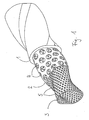
- the in Fig. 1 Stator shown has an outer tube 1 made of a solid material, for. As steel, in the interior of which the inner tubes 2 and 3 are located.
- the outer tube 1 closest inner tube 2 has openings 4.
- the inner tube 2 In the inner tube 2 is the inner tube 3.
- the lining 6 of the outer tube is in Fig. 1 not shown.
- the openings 4 of the inner tube 2 and the openings 5 of the inner tube 3 are in an advantageous embodiment of the invention of different sizes, in particular, the openings 4 are larger.
- the elastomer material of the lining surround the inner tube 3 through the openings 5, so that a particularly good adhesion between the lining 6 and the inner tube 3 and to the outer tube 1 is formed.
- the inner tube 3 is almost embedded in the elastomer composition. 6
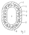
- Fig. 2 is a cross section of a stator shown as in Fig. 1 is shown.
- the inner tubes 2 and 3 which have the openings 4 and 5 in the outer tube 1.
- the lining 6 is shown in the outer tube 1.
- the lining 6 surrounds the bore 7, which is only roughly shown here.
- the bore 7 forms the space for receiving the material to be conveyed (pump cavity) if the stator is used in an eccentric screw pump, or the space for receiving the flowing drive means, if the stator is part of a used as a motor device.
- the bore 7 extends over the entire length of the stator. It is spiral-wound in two or more orbits and serves to receive a rotor, not shown here.
- the forces occurring during use of the pump are absorbed by the lining 6 and forwarded to the outer tube 1, via which the bearing of the pump takes place. For a firm connection between outer tube 1 and lining 2 must therefore be taken care of. This is done according to the invention by the inner tubes 2 and 3.
- the inner tubes 2 and 3 are arranged, which have a perforation or a plurality of openings 4 and 5 respectively.
- the openings 4 and 5 are filled by the material of the lining 6.
- a connection made by vulcanization or gluing between outer tube and lining can be omitted.
- the gluing or vulcanization is dispensed with.
- the bore 7 is helically wound.
- the outer tube 1 is shaped so that it runs parallel or nearly parallel to the outer contours of the cavity 7.
- a same, at least almost equal wall thickness of the lining 6 is achieved, which has proven to be advantageous in certain applications compared to stators with cylindrically shaped outer tubes.
- the inner tubes 2 and 3 can be formed by commercially available perforated plates, which are bent cylindrically. To produce a stator according to the invention, the inner tubes 2 and 3 are inserted into the outer tube 1 and all tubes 1, 2 and 3 are brought into the desired coiled shape. But it is also possible to first deform the tubes 1, 2 and 3 separately from each other, then put them together, such as by the inner tubes 2 and 3 are screwed into the outer tube 1. Subsequently, the rubber material of the lining 2 can be introduced by spraying.
- the inner tube 2 also from a hose made of elastomeric material or the like., In particular rubber exist.
- This hose not shown, is pushed over the inner tube 3.
- the inner tube 3 and the tube are then spent in the outer tube 1.
- the tube can also - as the inner tube 2 - have perforations, in which the elastomeric material of the liner 6 can flow.
- stator is made without a firmly adhering connection between the outer tube 1 and lining 2
- a mechanical, positive connection between the lining 2 and the inner tube 4 is formed, in contrast to stators with a chemical rubber-metal compound but can not be excluded be that it comes through a gap between the outer tube 1 and the liner 2 to a leakage and thus to a pressure drop between the suction side and pressure side of the pump. This can be prevented by a clamping seal at the front ends of the lining 2.
- Two embodiments of such a clamping gasket will be described below with reference to the Fig. 3 and 4 be explained.
- a conical sealing ring 10 is provided, which has a cylindrical portion 11, a conical portion 12 and a sealing bead 13.
- the conical portion 12 is spaced from the inside of the outer tube 1 and formed so that its distance from the outer tube 1 increases toward the interior of the stator.
- the sealing ring 10 is connected via a weld 14 to the outer tube 1.
- the sealing ring 10 may be connected by a press fit with the outer tube 1 instead of a welded joint.
- a clamping ring 15 is arranged on the sealing ring 10, which has a cylindrical portion 16, a conical portion 17 and a stop 18.
- the sealing ring 10 is introduced into the outer tube 1, positioned and possibly fixed there before the material (rubber) of the lining 2 is introduced into the outer tube 1.
- a conical annular gap 19 between the conical portion 12 of the sealing ring 10 and the outer tube 1 is filled with rubber.
- the rubber shrinks on cooling, however, both the outer tube 1 and the sealing ring 10 away.
- the clamping ring 15 is pressed axially.
- the wall thickness of the clamping ring 15 is greater in the conical portion 17 than the wall thickness of the conical portion 12 of the sealing ring 10. This ensures that the conical portion 17 of the clamping ring 15 presses the conical portion 12 of the sealing ring 10 to the outside.
- the sealing bead 13 of the sealing ring 10 prevents slipping out of the rubber from the annular gap 19 under conditions of use.
- a simple sealing ring 20 is provided in the embodiment according to Fig. 4 .
- This sealing ring 20 is suitable for installation after the introduction of the lining 2 in the outer tube.
- the liner 2 made of rubber or a similar material on the Injection process connected to the pipes 1 and 4.
- the end portion 21 of the lining 2 z. B. shaped as shown at 22 in dashed lines.
- the sealing ring 20 which is partially conical, is inserted into the outer tube 1.
- the end region 21 of the lining 2 is compressed by the conical region 24 of the sealing ring 20 and pressed firmly against the outer tube 1.
- the sealing ring 20 may, as shown at 23, connected by a weld with the outer tube 1 and secured against axial displacement. According to another embodiment of the invention, the sealing ring 20 may also be secured against displacement by a press fit between the sealing ring 20 and outer tube 20.
- Fig. 3 and 4 Possibilities for sealing the invention are shown. It is understood that these seals can be applied both in such stators, which z. B. have no coiled, but a cylindrical outer tube, as well as for coiled stators according to the Fig. 1 and 2 are suitable.
- the outer tube 1 may also have openings. It is not mandatory that the outer tube has a closed surface.
Abstract
Description
Die Erfindung betrifft einen Stator für eine Exzenterschneckenpumpe oder einen Exzenterschneckenmotor, der ein Außenrohr mit einer Auskleidung aus Gummi oder einem gummiähnlichen Werkstoff und einen nach Art eines zwei- oder mehrgängigen Steilgewindes geformten Hohlraum zur Aufnahme eines starren, ebenfalls nach Art eines Steilgewindes geformten Rotors aufweist, wobei der Stator jeweils einen Gang mehr aufweist als das Steilgewinde des Rotors.The invention relates to a stator for an eccentric screw pump or an eccentric screw motor having an outer tube with a lining made of rubber or a rubber-like material and a shaped like a two- or multi-start helix cavity for receiving a rigid, also shaped like a helical rotor, wherein the stator has in each case one more gear than the coarse thread of the rotor.
Die Wirkungsweise von Exzenterschneckenpumpen und -motoren wird auch als Moineau-Prinzip bezeichnet. Aus der
Es gibt Kautschuk-Typen, wie HNBR, Fluor-Kautschuke oder Silikon-Kautschuke, die bei Temperaturen von 160°C und höher funktionsfähig bleiben, jedoch ist auch bei diesen Kautschuken die Gummi-Metallverbindung problematisch, die im Dauereinsatz zerstört werden kann.There are rubber types, such as HNBR, fluorine rubbers or silicone rubbers, which remain functional at temperatures of 160 ° C and higher, but even with these rubbers, the rubber-metal compound is problematic, which can be destroyed in continuous use.
Der Erfindung liegt die Aufgabe zugrunde, einen Stator zur Verfügung zu stellen, der auch unter Bedingungen funktionsfähig bleibt, unter denen die festhaftende Bindung zwischen der Auskleidung und dem Außenrohr z. B. durch chemische Einflüsse oder hohe Temperaturen zerstört werden könnte.The invention has for its object to provide a stator that remains functional even under conditions under which the adherent bond between the liner and the outer tube z. B. could be destroyed by chemical influences or high temperatures.
Zur Lösung dieser Aufgabe sind erfindungsgemäß in der Auskleidung zwei Durchbrechungen aufweisende Rohre angeordnet.To achieve this object, two perforations having tubes are arranged according to the invention in the lining.
Zwischen der Gummischicht und den Durchbrechungen aufweisenden Rohren kommt es zu einer mechanischen Verkrallung bzw. einer formschlüssigen Verbindung. Die Durchbrechungen aufweisenden Rohre bewirken somit die Verbindung zwischen dem Außenrohr und der Auskleidung. Die die Durchbrechungen aufweisenden Rohre bestehen vorzugsweise aus Metall.Between the rubber layer and the openings having pipes there is a mechanical Verkrallung or a positive connection. The apertures having pipes thus effect the connection between the outer tube and the lining. The perforations having the tubes are preferably made of metal.
Der Stator weist nach der Erfindung zwei ineinander geschobene, gelochte Innenrohre mit deutlich unterschiedlichen Lochdurchmessern auf. Das hat den Vorteil, dass sich Hohlräume ergeben, die mit Gummi ausgefüllte Hinterschneidungen ergeben. Ein radiales Verlagern der Auskleidung unter Belastung wird dadurch wirksam verhindert.The stator has according to the invention two telescoped, perforated inner tubes with significantly different hole diameters. This has the advantage that voids arise that result in rubber-filled undercuts. A radial displacement of the lining under load is thereby effectively prevented.
Das innere Rohr der beiden Durchbrechungen aufweisenden Rohre wird beim Einbringen der Auskleidung von dieser naturgemäß mehr umschlossen als das Innenrohr, welches dem Außenrohr näher liegt. Das letztgenannte Rohr fungiert quasi als Abstandshalter und hat die Aufgabe, einen Mindestabstand zwischen dem inneren - Durchbrechungen aufweisenden - Rohr und dem Außenrohr zu gewährleisten. Die Auskleidung kann das innere Rohr vollständig oder nahezu vollständig umschließen. Die Auskleidung hat zudem Kontakt mit dem Außenrohr, nämlich durch die Durchbrechungen hindurch, welches das mittlere Rohr aufweist.The inner tube of the two openings having pipes is naturally more enclosed during introduction of the liner of this than the inner tube, which is closer to the outer tube. The latter tube acts more or less as a spacer and has the task to ensure a minimum distance between the inner - having perforations - tube and the outer tube. The lining may completely or nearly completely enclose the inner tube. The lining also has contact with the outer tube, namely through the apertures, which has the middle tube.
Bei der Herstellung des erfindungsgemäßen Stators kann die Gummierung, d.h. das Einbringen der Elastomer-Auskleidung in das Außenrohr ohne eine bindungsfreundliche Vorbehandlung der Metalloberflächen, etwa durch Verwendung eines Haftvermittlers, erfolgen. Die Gummierung kann jedoch auch unter Einsatz eines chemischen Bindungssystems, z. B. eines Haftvermittlers, erfolgen. Sollte nämlich die chemische Bindung zwischen Gummi und Metall im Einsatz chemisch, durch Hitzeeinwirkung und/oder durch mechanische Einwirkung zerstört werden, gewährleistet die mechanische Verkrallung weiterhin die Funktion des Stators.In the production of the stator according to the invention, the gumming, ie the introduction of the elastomer liner in the outer tube without a bond-friendly pretreatment of the metal surfaces, such as by using an adhesion promoter, take place. However, the gumming can also by using a chemical bonding system, eg. B. a bonding agent done. If, in fact, the chemical bond between rubber and metal in use is destroyed chemically, by the action of heat and / or by mechanical action, the mechanical locking furthermore ensures the function of the stator.
Weitere Einzelheiten der Erfindung werden anhand der Zeichnung erläutert, in der Ausführungsbeispiele der Erfindung dargestellt sind.Further details of the invention will be explained with reference to the drawing, are shown in the embodiments of the invention.
Es zeigen:
- Fig. 1
- eine perspektivische Darstellung einer Ausführungsform der Erfindung mit teilweise freigelegten Schichten (ohne Auskleidung)
- Fig. 2
- einen Querschnitt durch den Stator gemäß
Fig. 1 - Fig. 3
- einen Längsschnitt durch das Endstück einer weiteren Ausführungsform des erfindungsgemäßen Stators nach
Anspruch 2
und - Fig. 4
- einen Längsschnitt durch das Endstück einer weiteren Ausführungsform des erfindungsgemäßen Stators nach
Anspruch 2
- Fig. 1
- a perspective view of an embodiment of the invention with partially exposed layers (without lining)
- Fig. 2
- a cross section through the stator according to
Fig. 1 - Fig. 3
- a longitudinal section through the tail of a further embodiment of the stator according to the invention according to
claim 2
and - Fig. 4
- a longitudinal section through the tail of a further embodiment of the stator according to the invention according to
claim 2
Der in
In dem Innenrohr 2 befindet sich das Innenrohr 3. Die Auskleidung 6 des Außenrohres ist in
Die Durchbrechungen 4 des Innenrohres 2 und die Durchbrechungen 5 des Innenrohres 3 sind in einer vorteilhaften Ausführungsform der Erfindung unterschiedlich groß, insbesondere sind die Durchbrechungen 4 größer. Hierdurch kann das Elastomermaterial der Auskleidung das Innenrohr 3 durch die Durchbrechungen 5 hindurch umschließen, so dass eine besonders gute Haftung zwischen der Auskleidung 6 und dem Innenrohr 3 und zu dem Außenrohr 1 entsteht. Das Innenrohr 3 wird nahezu eingebettet in die Elastomermasse 6.The
In
Die Bohrung 7 bildet den Raum zur Aufnahme des Fördergutes (Pumpenhohlraum), falls der Stator bei einer Exzenterschneckenpumpe zum Einsatz kommt, bzw. den Raum zur Aufnahme des strömenden Antriebsmittels, falls der Stator Teil einer als Motor genutzten Vorrichtung ist. Die Bohrung 7 erstreckt sich über die gesamte Länge des Stators. Sie ist zwei- oder mehrgängig schneckenförmig gewunden und dient zur Aufnahme eines hier nicht dargestellten Rotors. Die beim Einsatz der Pumpe auftretenden Kräfte werden von der Auskleidung 6 aufgenommen und an das Außenrohr 1 weitergeleitet, über das die Lagerung der Pumpe erfolgt. Für eine feste Verbindung zwischen Außenrohr 1 und Auskleidung 2 muss daher gesorgt sein. Dieses geschieht erfindungsgemäß durch die Innenrohre 2 und 3.The
Wichtig ist nun, dass in dem Außenrohr 1 die Innenrohre 2 und 3 angeordnet sind, die eine Perforierung bzw. eine Vielzahl von Durchbrechungen 4 bzw. 5 aufweisen. Die Durchbrechungen 4 und 5 werden von dem Material der Auskleidung 6 ausgefüllt. Dadurch kommt es zu einer formschlüssigen Verbindung zwischen dem Außenrohr 1, den Innenrohren 2 und 3 und der Auskleidung 6, so dass die Auskleidung 2 sowohl gegen Verschiebung in Längsrichtung als auch gegen Verdrehen um ihre Achse gesichert ist. Eine durch Vulkanisation oder Kleben hergestellte Verbindung zwischen Außenrohr und Auskleidung kann entfallen. Für die Erfindung ist es jedoch nicht zwingend, dass auf die das Kleben oder die Vulkanisation verzichtet wird.It is now important that in the
Wie bereits erwähnt, ist die Bohrung 7 schneckenförmig gewunden. Das Außenrohr 1 ist so geformt, dass es parallel oder nahezu parallel zu den Aussenkonturen des Hohlraumes 7 verläuft. Dadurch wird eine gleiche, zumindest nahezu gleiche Wandstärke der Auskleidung 6 erreicht, was sich bei bestimmten Anwendungen als vorteilhaft erwiesen hat gegenüber Statoren mit zylindrisch geformten Außenrohren.As already mentioned, the
Die Innenrohre 2 und 3 können durch handelsübliche Lochbleche gebildet werden, die zylindrisch gebogen werden. Zur Herstellung eines erfindungsgemäßen Stators werden die Innenrohre 2 und 3 in das Außenrohr 1 eingesetzt und alle Rohre 1, 2 und 3 in die gewünschte gewendelte Form gebracht. Möglich ist aber auch die Rohre 1, 2 und 3 zunächst getrennt von einander zu verformen, um sie sodann zusammenzufügen, etwa indem die Innenrohre 2 und 3 in das Außenrohr 1 hineingedreht werden. Anschließend kann durch Spritzen das Gummimaterial der Auskleidung 2 eingebracht werden.The
Nach einer vorteilhaften Ausführungsform kann das Innenrohr 2 auch aus einem Schlauch aus Elastomermaterial oder dergl., insbesondere Gummi, bestehen. Dieser nicht dargestellte Schlauch wird über das Innenrohr 3 geschoben. Das Innenrohr 3 und der Schlauch werden sodann in das Außenrohr 1 verbracht. Es versteht sich von selbst, dass der Schlauch auch - wie das Innenrohr 2 - Durchbrechungen aufweisen kann, in die das Elastomermaterial der Auskleidung 6 fließen kann.According to an advantageous embodiment, the
Im Falle, dass der Stator ganz ohne eine festhaftende Verbindung zwischen Außenrohr 1 und Auskleidung 2 hergestellt wird, entsteht zwar eine mechanische, formschlüssige Verbindung zwischen der Auskleidung 2 und dem Innenrohr 4, im Gegensatz zu Statoren mit einer chemischen Gummi-MetallVerbindung kann aber nicht ausgeschlossen werden, dass es über einen Spalt zwischen dem Außenrohr 1 und der Auskleidung 2 zu einer Leckage und damit zu einem Druckabfall zwischen Saugseite und Druckseite der Pumpe kommt. Dies kann durch eine Klemmdichtung an den stirnseitigen Enden der Auskleidung 2 verhindert werden. Zwei Ausführungsbeispiele für eine derartige Klemmdichtung sollen im Folgenden anhand der
Bei der Ausführungsform gemäß
Weiterhin ist an dem Dichtring 10 ein Klemmring 15 angeordnet, der einen zylindrischen Abschnitt 16, einen konischen Abschnitt 17 und einen Anschlag 18 aufweist.Furthermore, a clamping
Bei der Herstellung des Stators wird der Dichtring 10 in das Außenrohr 1 eingebracht, positioniert und ggf. dort befestigt, bevor der Werkstoff (Gummi) der Auskleidung 2 in das Außenrohr 1 eingebracht wird. Nach dem Einbringen des Gummis ist ein konischer Ringspalt 19 zwischen dem konischen Abschnitt 12 des Dichtrings 10 und dem Außenrohr 1 mit Gummi ausgefüllt. Erfahrungsgemäß schrumpft der Gummi beim Erkalten jedoch sowohl vom Außenrohr 1 als auch vom Dichtring 10 weg. Um die dabei entstehenden Spalte zu verschließen und den Gummi im Ringspalt 19 zwischen dem konischen Abschnitt 14 des Dichtringes 10 und dem Außenrohr 1 dichtend zu verpressen, wird der Klemmring 15 axial eingepresst. Die Wandstärke des Klemmrings 15 ist im konischen Abschnitt 17 größer als die Wandstärke des konischen Abschnitts 12 des Dichtrings 10. Dadurch ist gewährleistet, dass der konische Abschnitt 17 des Klemmrings 15 den konischen Abschnitt 12 des Dichtrings 10 nach außen drückt. Der Dichtwulst 13 des Dichtringes 10 verhindert ein Herausrutschen des Gummis aus dem Ringspalt 19 unter Einsatzbedingungen.In the manufacture of the stator, the sealing
Bei der Ausführungsform gemäß
Bei der Herstellung des Stators gemäß
Der Dichtring 20 kann, wie bei 23 dargestellt, durch eine Schweißnaht mit dem Außenrohr 1 verbunden und so gegen axiales Verschieben gesichert sein. Nach einer anderen Ausführungsform der Erfindung kann der Dichtring 20 auch durch eine Presspassung zwischen Dichtring 20 und Außenrohr 20 gegen Verschieben gesichert sein.The sealing
In
Nach einer hier nicht dargestellten Ausführungsform der Erfindung kann das Außenrohr 1 ebenfalls Durchbrechungen aufweisen. Es ist nicht zwingend, dass das Außenrohr eine geschlossene Oberfläche besitzt.According to an embodiment of the invention, not shown here, the
Claims (13)
Applications Claiming Priority (2)
| Application Number | Priority Date | Filing Date | Title |
|---|---|---|---|
| US10/714,812 US7131827B2 (en) | 2003-11-17 | 2003-11-17 | Stator for an eccentric screw pump or an eccentric worm motor operating on the moineau principle |
| EP04803164A EP1738078B1 (en) | 2003-11-17 | 2004-11-17 | Stator for an eccentric screw pump or an eccentric screw motor according to the moineau principle |
Related Parent Applications (1)
| Application Number | Title | Priority Date | Filing Date |
|---|---|---|---|
| EP04803164A Division EP1738078B1 (en) | 2003-11-17 | 2004-11-17 | Stator for an eccentric screw pump or an eccentric screw motor according to the moineau principle |
Publications (3)
| Publication Number | Publication Date |
|---|---|
| EP2028372A2 true EP2028372A2 (en) | 2009-02-25 |
| EP2028372A3 EP2028372A3 (en) | 2014-08-27 |
| EP2028372B1 EP2028372B1 (en) | 2015-07-29 |
Family
ID=34574064
Family Applications (2)
| Application Number | Title | Priority Date | Filing Date |
|---|---|---|---|
| EP04803164A Expired - Fee Related EP1738078B1 (en) | 2003-11-17 | 2004-11-17 | Stator for an eccentric screw pump or an eccentric screw motor according to the moineau principle |
| EP08018529.1A Expired - Fee Related EP2028372B1 (en) | 2003-11-17 | 2004-11-17 | Stator for an eccentric screw pump or an eccentric screw motor in accordance with the Moineau principle |
Family Applications Before (1)
| Application Number | Title | Priority Date | Filing Date |
|---|---|---|---|
| EP04803164A Expired - Fee Related EP1738078B1 (en) | 2003-11-17 | 2004-11-17 | Stator for an eccentric screw pump or an eccentric screw motor according to the moineau principle |
Country Status (6)
| Country | Link |
|---|---|
| US (2) | US7131827B2 (en) |
| EP (2) | EP1738078B1 (en) |
| BR (1) | BRPI0416662B1 (en) |
| CA (2) | CA2473001C (en) |
| DE (1) | DE502004009512D1 (en) |
| WO (1) | WO2005047702A2 (en) |
Families Citing this family (16)
| Publication number | Priority date | Publication date | Assignee | Title |
|---|---|---|---|---|
| US7407372B2 (en) | 2004-05-14 | 2008-08-05 | Robbins & Myers Energy Systems L.P. | Progressing cavity pump or motor |
| GB2424452B (en) * | 2005-03-22 | 2011-01-19 | Schlumberger Holdings | Progressive cavity motor with rotor having an elastomer sleeve |
| DE102008054961A1 (en) * | 2008-12-19 | 2010-07-01 | Endress + Hauser Flowtec Ag | Flow meter and method of making a meter tube of a flow meter |
| JP5364461B2 (en) * | 2009-06-17 | 2013-12-11 | 宇明泰化工股▲ふん▼有限公司 | Polytetrafluoroethylene twisted yarn and method for producing the same |
| US8523545B2 (en) * | 2009-12-21 | 2013-09-03 | Baker Hughes Incorporated | Stator to housing lock in a progressing cavity pump |
| GB2481226A (en) | 2010-06-16 | 2011-12-21 | Nat Oilwell Varco Lp | Stator for a progressive cavity (PC) pump or motor |
| WO2012026085A1 (en) * | 2010-08-25 | 2012-03-01 | 古河産機システムズ株式会社 | Stator seal structure for single-shaft eccentric screw pump |
| US8672656B2 (en) | 2010-12-20 | 2014-03-18 | Robbins & Myers Energy Systems L.P. | Progressing cavity pump/motor |
| GB2551304B (en) | 2012-02-22 | 2018-02-28 | Nat Oilwell Varco Lp | Stator for progressive cavity pump/motor |
| DE102012112044B4 (en) * | 2012-05-04 | 2015-10-08 | Netzsch Pumpen & Systeme Gmbh | Self-fixing stator housing |
| WO2015123288A2 (en) * | 2014-02-12 | 2015-08-20 | Roper Pump Company | Hybrid elastomer/metal on metal motor |
| CN108050058B (en) * | 2017-12-06 | 2019-06-25 | 中石化石油机械股份有限公司研究院 | Oil-extracting screw pump |
| US11655815B2 (en) | 2019-12-13 | 2023-05-23 | Roper Pump Company, Llc | Semi-rigid stator |
| DE102020004334A1 (en) | 2020-07-20 | 2022-01-20 | Wilhelm Kächele GmbH | Stator for progressing cavity machine |
| DE102021130260A1 (en) | 2021-11-19 | 2023-05-25 | Wilhelm Kächele GmbH | Stator for eccentric screw machine and manufacturing method for this |
| WO2023152594A1 (en) * | 2022-02-14 | 2023-08-17 | Johnson & Johnson Surgical Vision, Inc. | A sealing assembly for a progressive cavity pump |
Family Cites Families (19)
| Publication number | Priority date | Publication date | Assignee | Title |
|---|---|---|---|---|
| US2700936A (en) * | 1951-10-05 | 1955-02-01 | Thompson Prod Inc | Flexible helix rotor pump |
| US2862454A (en) * | 1954-06-25 | 1958-12-02 | Robbins & Myers | Helical gear pumps |
| FR1414025A (en) * | 1964-09-03 | 1965-10-15 | Loire Atel Forges | Improvements to extruding machines |
| US3139035A (en) * | 1960-10-24 | 1964-06-30 | Walter J O'connor | Cavity pump mechanism |
| DE1553199C3 (en) * | 1966-03-15 | 1974-03-07 | Karl Dipl.-Ing. 7024 Bernhausen Schlecht | Adjustable stator for an eccentric screw pump |
| GB1211987A (en) * | 1968-04-29 | 1970-11-11 | Stenberg Flygt Ab | A screw pump provided with a radially movable rotor coupling |
| DE2250263C3 (en) * | 1972-10-13 | 1978-09-28 | Gummi-Jaeger Kg Gmbh & Cie, 3000 Hannover | Adjustable stator for eccentric screw pumps |
| DE2541779A1 (en) * | 1975-09-19 | 1977-03-31 | Allweiler Ag | Stator with prefabricated lining for eccentric screw pump - preventing internal stress due to shrinkage of resilient material |
| DE2713468C3 (en) * | 1977-03-26 | 1982-09-02 | Allweiler Ag, 7760 Radolfzell | Stator for progressing cavity pumps |
| JPS61180512A (en) * | 1986-01-21 | 1986-08-13 | 日立電線株式会社 | Construction of directly cooled type power cable line |
| US5171139A (en) * | 1991-11-26 | 1992-12-15 | Smith International, Inc. | Moineau motor with conduits through the stator |
| DE4403598A1 (en) * | 1994-02-07 | 1995-08-10 | Arnold Jaeger | Eccentric screw pump for supplying mortar |
| DE19804260C2 (en) * | 1998-02-04 | 2003-04-10 | Artemis Kautschuk Kunststoff | Elastomer stator for an eccentric screw pump |
| DE19827101A1 (en) * | 1998-06-18 | 1999-12-23 | Artemis Kautschuk Kunststoff | Machine used in deep drilling, especially in crude oil recovery |
| DE19842754C2 (en) | 1998-09-18 | 2001-04-26 | Seepex Seeberger Gmbh & Co | Eccentric screw pump |
| DE29822365U1 (en) * | 1998-12-16 | 1999-04-01 | Artemis Kautschuk Kunststoff | Elastomer stator for eccentric screw pumps |
| DE29909039U1 (en) * | 1999-05-22 | 1999-09-23 | Wagner Gmbh J | Feed pump with feed line |
| DE19950257B4 (en) * | 1999-10-18 | 2013-01-17 | Wilhelm Kächele GmbH Elastomertechnik | Eccentric screw pump with fully lined stator |
| DE20013030U1 (en) * | 2000-07-20 | 2000-12-07 | Artemis Kautschuk Kunststoff | Anti-rotation device for stators of eccentric screw pumps |
-
2003
- 2003-11-17 US US10/714,812 patent/US7131827B2/en not_active Expired - Lifetime
-
2004
- 2004-07-06 CA CA2473001A patent/CA2473001C/en not_active Expired - Fee Related
- 2004-07-06 CA CA2712364A patent/CA2712364C/en not_active Expired - Fee Related
- 2004-11-17 EP EP04803164A patent/EP1738078B1/en not_active Expired - Fee Related
- 2004-11-17 WO PCT/EP2004/013037 patent/WO2005047702A2/en active Application Filing
- 2004-11-17 DE DE502004009512T patent/DE502004009512D1/en active Active
- 2004-11-17 EP EP08018529.1A patent/EP2028372B1/en not_active Expired - Fee Related
- 2004-11-17 BR BRPI0416662A patent/BRPI0416662B1/en not_active IP Right Cessation
-
2006
- 2006-11-07 US US11/593,740 patent/US7329106B2/en not_active Expired - Fee Related
Also Published As
| Publication number | Publication date |
|---|---|
| CA2712364A1 (en) | 2005-05-17 |
| CA2712364C (en) | 2013-08-27 |
| EP1738078B1 (en) | 2009-05-20 |
| CA2473001A1 (en) | 2005-05-17 |
| US7329106B2 (en) | 2008-02-12 |
| WO2005047702A2 (en) | 2005-05-26 |
| WO2005047702A3 (en) | 2005-11-24 |
| US20070053783A1 (en) | 2007-03-08 |
| EP2028372B1 (en) | 2015-07-29 |
| US20050106052A1 (en) | 2005-05-19 |
| EP1738078A2 (en) | 2007-01-03 |
| EP2028372A3 (en) | 2014-08-27 |
| BRPI0416662B1 (en) | 2017-02-07 |
| BRPI0416662A (en) | 2007-01-16 |
| US7131827B2 (en) | 2006-11-07 |
| DE502004009512D1 (en) | 2009-07-02 |
| CA2473001C (en) | 2011-04-19 |
Similar Documents
| Publication | Publication Date | Title |
|---|---|---|
| EP2028372A2 (en) | Stator for an eccentric screw pump or an eccentric screw motor in accordance with the Moineau principle | |
| EP2994640B1 (en) | Stator for a feed pump | |
| DE102005014128B4 (en) | Composite hose and method for its manufacture | |
| CH631533A5 (en) | FORM-FITTED PIPE CONNECTION AND METHOD FOR THEIR PRODUCTION. | |
| EP2256345A2 (en) | Stator for an eccentric screw pump or an eccentric screw motor and method for producing a stator | |
| EP2640535B1 (en) | Method and set of components for producing a tubular structural part, in particular a built-up camshaft | |
| DE4108741C2 (en) | ||
| DE19950257B4 (en) | Eccentric screw pump with fully lined stator | |
| DE102005028818B3 (en) | Stator for an eccentric screw pump comprises axially arranged stator segments connected pressure-tight on their contact points by a tube pulled onto a casing and overlapping the contact points and a radially flattened metal ring | |
| EP1129292B1 (en) | Worm for an eccentric screw pump or a subsurface drilling motor | |
| DE10338632B4 (en) | Eccentric screw pump with erosion-resistant rotor | |
| WO2014173652A2 (en) | Metal pipe having a connector | |
| EP1222396A1 (en) | Stator with rigid retaining ring | |
| DE202014103665U1 (en) | Stator of an eccentric screw pump for conveying a flowable conveying mass, in particular a building material mixture such as mortar | |
| WO2019180171A1 (en) | Hybrid pipe having pipe collar and wear ring, and method for producing same | |
| EP2196716B1 (en) | Hose coupling | |
| DE102019005367B4 (en) | Method for producing a stator component for an eccentric screw pump, stator component and eccentric screw pump | |
| DE10049047C2 (en) | Method of manufacturing a camshaft and camshaft produced thereafter | |
| DE19516830A1 (en) | Pressing tools and methods for connecting tubular elements | |
| EP2730829A1 (en) | Plastic pipe | |
| EP0119520B1 (en) | Connection device for a flexible tube | |
| DE102017100540B4 (en) | Cavity Pump | |
| DE102009008430A1 (en) | Tube-shaped shell wall manufacturing method for elastomer stator of eccentric screw pump that is utilized for conveying plaster, involves deforming non-pre-formed semi-finished product corresponding to negative mold | |
| DE69912149T2 (en) | CONNECTING DEVICE OF A METALLIC PIPING | |
| EP2042797A1 (en) | Connecting assembly for strip wound hoses |
Legal Events
| Date | Code | Title | Description |
|---|---|---|---|
| PUAI | Public reference made under article 153(3) epc to a published international application that has entered the european phase |
Free format text: ORIGINAL CODE: 0009012 |
|
| AC | Divisional application: reference to earlier application |
Ref document number: 1738078 Country of ref document: EP Kind code of ref document: P |
|
| AK | Designated contracting states |
Kind code of ref document: A2 Designated state(s): DE FR GB |
|
| PUAL | Search report despatched |
Free format text: ORIGINAL CODE: 0009013 |
|
| PUAF | Information related to the publication of a search report (a3 document) modified or deleted |
Free format text: ORIGINAL CODE: 0009199SEPU |
|
| PUAL | Search report despatched |
Free format text: ORIGINAL CODE: 0009013 |
|
| PUAF | Information related to the publication of a search report (a3 document) modified or deleted |
Free format text: ORIGINAL CODE: 0009199SEPU |
|
| PUAL | Search report despatched |
Free format text: ORIGINAL CODE: 0009013 |
|
| AK | Designated contracting states |
Kind code of ref document: A3 Designated state(s): DE FR GB |
|
| RIC1 | Information provided on ipc code assigned before grant |
Ipc: F04C 2/107 20060101AFI20140624BHEP |
|
| D17D | Deferred search report published (deleted) | ||
| RIC1 | Information provided on ipc code assigned before grant |
Ipc: F04C 2/107 20060101AFI20140703BHEP |
|
| AK | Designated contracting states |
Kind code of ref document: A3 Designated state(s): DE FR GB |
|
| D17D | Deferred search report published (deleted) | ||
| AK | Designated contracting states |
Kind code of ref document: A3 Designated state(s): DE FR GB |
|
| RIC1 | Information provided on ipc code assigned before grant |
Ipc: F04C 2/107 20060101AFI20140718BHEP |
|
| RIC1 | Information provided on ipc code assigned before grant |
Ipc: F04C 2/107 20060101AFI20140804BHEP |
|
| 17P | Request for examination filed |
Effective date: 20150224 |
|
| RBV | Designated contracting states (corrected) |
Designated state(s): DE FR GB |
|
| GRAP | Despatch of communication of intention to grant a patent |
Free format text: ORIGINAL CODE: EPIDOSNIGR1 |
|
| AKX | Designation fees paid |
Designated state(s): DE FR GB |
|
| GRAS | Grant fee paid |
Free format text: ORIGINAL CODE: EPIDOSNIGR3 |
|
| INTG | Intention to grant announced |
Effective date: 20150428 |
|
| GRAA | (expected) grant |
Free format text: ORIGINAL CODE: 0009210 |
|
| AC | Divisional application: reference to earlier application |
Ref document number: 1738078 Country of ref document: EP Kind code of ref document: P |
|
| AK | Designated contracting states |
Kind code of ref document: B1 Designated state(s): DE FR GB |
|
| REG | Reference to a national code |
Ref country code: GB Ref legal event code: FG4D Free format text: NOT ENGLISH |
|
| REG | Reference to a national code |
Ref country code: DE Ref legal event code: R096 Ref document number: 502004014981 Country of ref document: DE |
|
| REG | Reference to a national code |
Ref country code: FR Ref legal event code: PLFP Year of fee payment: 12 |
|
| REG | Reference to a national code |
Ref country code: DE Ref legal event code: R097 Ref document number: 502004014981 Country of ref document: DE |
|
| PLBE | No opposition filed within time limit |
Free format text: ORIGINAL CODE: 0009261 |
|
| STAA | Information on the status of an ep patent application or granted ep patent |
Free format text: STATUS: NO OPPOSITION FILED WITHIN TIME LIMIT |
|
| 26N | No opposition filed |
Effective date: 20160502 |
|
| REG | Reference to a national code |
Ref country code: FR Ref legal event code: PLFP Year of fee payment: 13 |
|
| REG | Reference to a national code |
Ref country code: FR Ref legal event code: PLFP Year of fee payment: 14 |
|
| PGFP | Annual fee paid to national office [announced via postgrant information from national office to epo] |
Ref country code: FR Payment date: 20171124 Year of fee payment: 14 |
|
| PGFP | Annual fee paid to national office [announced via postgrant information from national office to epo] |
Ref country code: GB Payment date: 20171124 Year of fee payment: 14 |
|
| PGFP | Annual fee paid to national office [announced via postgrant information from national office to epo] |
Ref country code: DE Payment date: 20180116 Year of fee payment: 14 |
|
| REG | Reference to a national code |
Ref country code: DE Ref legal event code: R119 Ref document number: 502004014981 Country of ref document: DE |
|
| GBPC | Gb: european patent ceased through non-payment of renewal fee |
Effective date: 20181117 |
|
| PG25 | Lapsed in a contracting state [announced via postgrant information from national office to epo] |
Ref country code: FR Free format text: LAPSE BECAUSE OF NON-PAYMENT OF DUE FEES Effective date: 20181130 Ref country code: DE Free format text: LAPSE BECAUSE OF NON-PAYMENT OF DUE FEES Effective date: 20190601 |
|
| PG25 | Lapsed in a contracting state [announced via postgrant information from national office to epo] |
Ref country code: GB Free format text: LAPSE BECAUSE OF NON-PAYMENT OF DUE FEES Effective date: 20181117 |