EP2028362A2 - Fuel temperature control by exploiting system inactivity - Google Patents
Fuel temperature control by exploiting system inactivity Download PDFInfo
- Publication number
- EP2028362A2 EP2028362A2 EP08014585A EP08014585A EP2028362A2 EP 2028362 A2 EP2028362 A2 EP 2028362A2 EP 08014585 A EP08014585 A EP 08014585A EP 08014585 A EP08014585 A EP 08014585A EP 2028362 A2 EP2028362 A2 EP 2028362A2
- Authority
- EP
- European Patent Office
- Prior art keywords
- fuel
- internal combustion
- combustion engine
- fuel temperature
- temperature
- Prior art date
- Legal status (The legal status is an assumption and is not a legal conclusion. Google has not performed a legal analysis and makes no representation as to the accuracy of the status listed.)
- Withdrawn
Links
Images
Classifications
-
- F—MECHANICAL ENGINEERING; LIGHTING; HEATING; WEAPONS; BLASTING
- F02—COMBUSTION ENGINES; HOT-GAS OR COMBUSTION-PRODUCT ENGINE PLANTS
- F02M—SUPPLYING COMBUSTION ENGINES IN GENERAL WITH COMBUSTIBLE MIXTURES OR CONSTITUENTS THEREOF
- F02M37/00—Apparatus or systems for feeding liquid fuel from storage containers to carburettors or fuel-injection apparatus; Arrangements for purifying liquid fuel specially adapted for, or arranged on, internal-combustion engines
- F02M37/0047—Layout or arrangement of systems for feeding fuel
- F02M37/0064—Layout or arrangement of systems for feeding fuel for engines being fed with multiple fuels or fuels having special properties, e.g. bio-fuels; varying the fuel composition
-
- F—MECHANICAL ENGINEERING; LIGHTING; HEATING; WEAPONS; BLASTING
- F02—COMBUSTION ENGINES; HOT-GAS OR COMBUSTION-PRODUCT ENGINE PLANTS
- F02D—CONTROLLING COMBUSTION ENGINES
- F02D19/00—Controlling engines characterised by their use of non-liquid fuels, pluralities of fuels, or non-fuel substances added to the combustible mixtures
- F02D19/06—Controlling engines characterised by their use of non-liquid fuels, pluralities of fuels, or non-fuel substances added to the combustible mixtures peculiar to engines working with pluralities of fuels, e.g. alternatively with light and heavy fuel oil, other than engines indifferent to the fuel consumed
- F02D19/0602—Control of components of the fuel supply system
- F02D19/0605—Control of components of the fuel supply system to adjust the fuel pressure or temperature
-
- F—MECHANICAL ENGINEERING; LIGHTING; HEATING; WEAPONS; BLASTING
- F02—COMBUSTION ENGINES; HOT-GAS OR COMBUSTION-PRODUCT ENGINE PLANTS
- F02D—CONTROLLING COMBUSTION ENGINES
- F02D19/00—Controlling engines characterised by their use of non-liquid fuels, pluralities of fuels, or non-fuel substances added to the combustible mixtures
- F02D19/06—Controlling engines characterised by their use of non-liquid fuels, pluralities of fuels, or non-fuel substances added to the combustible mixtures peculiar to engines working with pluralities of fuels, e.g. alternatively with light and heavy fuel oil, other than engines indifferent to the fuel consumed
- F02D19/0639—Controlling engines characterised by their use of non-liquid fuels, pluralities of fuels, or non-fuel substances added to the combustible mixtures peculiar to engines working with pluralities of fuels, e.g. alternatively with light and heavy fuel oil, other than engines indifferent to the fuel consumed characterised by the type of fuels
- F02D19/0649—Liquid fuels having different boiling temperatures, volatilities, densities, viscosities, cetane or octane numbers
- F02D19/0652—Biofuels, e.g. plant oils
-
- F—MECHANICAL ENGINEERING; LIGHTING; HEATING; WEAPONS; BLASTING
- F02—COMBUSTION ENGINES; HOT-GAS OR COMBUSTION-PRODUCT ENGINE PLANTS
- F02D—CONTROLLING COMBUSTION ENGINES
- F02D19/00—Controlling engines characterised by their use of non-liquid fuels, pluralities of fuels, or non-fuel substances added to the combustible mixtures
- F02D19/06—Controlling engines characterised by their use of non-liquid fuels, pluralities of fuels, or non-fuel substances added to the combustible mixtures peculiar to engines working with pluralities of fuels, e.g. alternatively with light and heavy fuel oil, other than engines indifferent to the fuel consumed
- F02D19/0663—Details on the fuel supply system, e.g. tanks, valves, pipes, pumps, rails, injectors or mixers
- F02D19/0668—Treating or cleaning means; Fuel filters
-
- F—MECHANICAL ENGINEERING; LIGHTING; HEATING; WEAPONS; BLASTING
- F02—COMBUSTION ENGINES; HOT-GAS OR COMBUSTION-PRODUCT ENGINE PLANTS
- F02D—CONTROLLING COMBUSTION ENGINES
- F02D19/00—Controlling engines characterised by their use of non-liquid fuels, pluralities of fuels, or non-fuel substances added to the combustible mixtures
- F02D19/06—Controlling engines characterised by their use of non-liquid fuels, pluralities of fuels, or non-fuel substances added to the combustible mixtures peculiar to engines working with pluralities of fuels, e.g. alternatively with light and heavy fuel oil, other than engines indifferent to the fuel consumed
- F02D19/0663—Details on the fuel supply system, e.g. tanks, valves, pipes, pumps, rails, injectors or mixers
- F02D19/0684—High pressure fuel injection systems; Details on pumps, rails or the arrangement of valves in the fuel supply and return systems
-
- F—MECHANICAL ENGINEERING; LIGHTING; HEATING; WEAPONS; BLASTING
- F02—COMBUSTION ENGINES; HOT-GAS OR COMBUSTION-PRODUCT ENGINE PLANTS
- F02M—SUPPLYING COMBUSTION ENGINES IN GENERAL WITH COMBUSTIBLE MIXTURES OR CONSTITUENTS THEREOF
- F02M31/00—Apparatus for thermally treating combustion-air, fuel, or fuel-air mixture
- F02M31/02—Apparatus for thermally treating combustion-air, fuel, or fuel-air mixture for heating
- F02M31/16—Other apparatus for heating fuel
-
- F—MECHANICAL ENGINEERING; LIGHTING; HEATING; WEAPONS; BLASTING
- F02—COMBUSTION ENGINES; HOT-GAS OR COMBUSTION-PRODUCT ENGINE PLANTS
- F02D—CONTROLLING COMBUSTION ENGINES
- F02D19/00—Controlling engines characterised by their use of non-liquid fuels, pluralities of fuels, or non-fuel substances added to the combustible mixtures
- F02D19/06—Controlling engines characterised by their use of non-liquid fuels, pluralities of fuels, or non-fuel substances added to the combustible mixtures peculiar to engines working with pluralities of fuels, e.g. alternatively with light and heavy fuel oil, other than engines indifferent to the fuel consumed
- F02D19/0602—Control of components of the fuel supply system
- F02D19/0613—Switch-over from one fuel to another
- F02D19/0615—Switch-over from one fuel to another being initiated by automatic means, e.g. based on engine or vehicle operating conditions
-
- F—MECHANICAL ENGINEERING; LIGHTING; HEATING; WEAPONS; BLASTING
- F02—COMBUSTION ENGINES; HOT-GAS OR COMBUSTION-PRODUCT ENGINE PLANTS
- F02D—CONTROLLING COMBUSTION ENGINES
- F02D19/00—Controlling engines characterised by their use of non-liquid fuels, pluralities of fuels, or non-fuel substances added to the combustible mixtures
- F02D19/06—Controlling engines characterised by their use of non-liquid fuels, pluralities of fuels, or non-fuel substances added to the combustible mixtures peculiar to engines working with pluralities of fuels, e.g. alternatively with light and heavy fuel oil, other than engines indifferent to the fuel consumed
- F02D19/0626—Measuring or estimating parameters related to the fuel supply system
- F02D19/0628—Determining the fuel pressure, temperature or flow, the fuel tank fill level or a valve position
-
- F—MECHANICAL ENGINEERING; LIGHTING; HEATING; WEAPONS; BLASTING
- F02—COMBUSTION ENGINES; HOT-GAS OR COMBUSTION-PRODUCT ENGINE PLANTS
- F02D—CONTROLLING COMBUSTION ENGINES
- F02D41/00—Electrical control of supply of combustible mixture or its constituents
- F02D41/02—Circuit arrangements for generating control signals
- F02D41/14—Introducing closed-loop corrections
- F02D41/1401—Introducing closed-loop corrections characterised by the control or regulation method
- F02D2041/1409—Introducing closed-loop corrections characterised by the control or regulation method using at least a proportional, integral or derivative controller
-
- F—MECHANICAL ENGINEERING; LIGHTING; HEATING; WEAPONS; BLASTING
- F02—COMBUSTION ENGINES; HOT-GAS OR COMBUSTION-PRODUCT ENGINE PLANTS
- F02D—CONTROLLING COMBUSTION ENGINES
- F02D41/00—Electrical control of supply of combustible mixture or its constituents
- F02D41/02—Circuit arrangements for generating control signals
- F02D41/14—Introducing closed-loop corrections
- F02D41/1401—Introducing closed-loop corrections characterised by the control or regulation method
- F02D2041/1413—Controller structures or design
- F02D2041/1422—Variable gain or coefficients
-
- F—MECHANICAL ENGINEERING; LIGHTING; HEATING; WEAPONS; BLASTING
- F02—COMBUSTION ENGINES; HOT-GAS OR COMBUSTION-PRODUCT ENGINE PLANTS
- F02D—CONTROLLING COMBUSTION ENGINES
- F02D41/00—Electrical control of supply of combustible mixture or its constituents
- F02D41/20—Output circuits, e.g. for controlling currents in command coils
- F02D2041/202—Output circuits, e.g. for controlling currents in command coils characterised by the control of the circuit
- F02D2041/2024—Output circuits, e.g. for controlling currents in command coils characterised by the control of the circuit the control switching a load after time-on and time-off pulses
- F02D2041/2027—Control of the current by pulse width modulation or duty cycle control
-
- F—MECHANICAL ENGINEERING; LIGHTING; HEATING; WEAPONS; BLASTING
- F02—COMBUSTION ENGINES; HOT-GAS OR COMBUSTION-PRODUCT ENGINE PLANTS
- F02D—CONTROLLING COMBUSTION ENGINES
- F02D2200/00—Input parameters for engine control
- F02D2200/02—Input parameters for engine control the parameters being related to the engine
- F02D2200/06—Fuel or fuel supply system parameters
- F02D2200/0606—Fuel temperature
-
- Y—GENERAL TAGGING OF NEW TECHNOLOGICAL DEVELOPMENTS; GENERAL TAGGING OF CROSS-SECTIONAL TECHNOLOGIES SPANNING OVER SEVERAL SECTIONS OF THE IPC; TECHNICAL SUBJECTS COVERED BY FORMER USPC CROSS-REFERENCE ART COLLECTIONS [XRACs] AND DIGESTS
- Y02—TECHNOLOGIES OR APPLICATIONS FOR MITIGATION OR ADAPTATION AGAINST CLIMATE CHANGE
- Y02T—CLIMATE CHANGE MITIGATION TECHNOLOGIES RELATED TO TRANSPORTATION
- Y02T10/00—Road transport of goods or passengers
- Y02T10/10—Internal combustion engine [ICE] based vehicles
- Y02T10/12—Improving ICE efficiencies
-
- Y—GENERAL TAGGING OF NEW TECHNOLOGICAL DEVELOPMENTS; GENERAL TAGGING OF CROSS-SECTIONAL TECHNOLOGIES SPANNING OVER SEVERAL SECTIONS OF THE IPC; TECHNICAL SUBJECTS COVERED BY FORMER USPC CROSS-REFERENCE ART COLLECTIONS [XRACs] AND DIGESTS
- Y02—TECHNOLOGIES OR APPLICATIONS FOR MITIGATION OR ADAPTATION AGAINST CLIMATE CHANGE
- Y02T—CLIMATE CHANGE MITIGATION TECHNOLOGIES RELATED TO TRANSPORTATION
- Y02T10/00—Road transport of goods or passengers
- Y02T10/10—Internal combustion engine [ICE] based vehicles
- Y02T10/30—Use of alternative fuels, e.g. biofuels
Definitions
- the invention relates to an internal combustion engine, in particular a self-igniting internal combustion engine, which is operable with a viscous fuel, in particular rapeseed oil, wherein the fuel from a tank via a fuel line from a feed pump via a fuel filter in a high-pressure pump device is conveyed and wherein the fuel from a heater heated up is and a method for fuel temperature control of such an internal combustion engine.
- a self-igniting internal combustion engine which is operable with a viscous fuel, in particular rapeseed oil, wherein the fuel from a tank via a fuel line from a feed pump via a fuel filter in a high-pressure pump device is conveyed and wherein the fuel from a heater heated up is and a method for fuel temperature control of such an internal combustion engine.
- Such an internal combustion engine is from the DE 38 00 585 known.
- a high-pressure fuel pump is optionally supplied with diesel fuel or rapeseed oil. It is intended to heat the viscous rapeseed oil via an electric heater, which is arranged in the rapeseed oil tank. Since the rapeseed oil should advantageously be heated to temperatures higher than 50 ° C., a considerable expenditure of energy is therefore required for heating up the entire amount of fuel entrained in the tank. About a regulation for adjusting a certain predetermined temperature nothing is executed.
- the invention has for its object to provide an apparatus and a method for fuel temperature control, with a reliable and accurate temperature control is possible with low energy consumption.
- the heating device is a heat exchanger which is switched into the fuel line and is flowed through by a heat-transmitting cooling medium of the internal combustion engine as a function of a fuel temperature setpoint and a fuel temperature measurement.
- the valve is a 2/2-way valve.
- Such a valve is inexpensive and reliable, and by the clocked control of the valve provided in a further embodiment, a very accurate and reliable setting of a temperature is possible.
- An accurate fuel temperature control is a crucial component for the proper operation of a rapeseed oil fueled engine in terms of performance, fuel consumption and emissions.
- the principle used here for the accurate fuel temperature control is a (slow) clocking (open / closed) of the 2/2-way valve, which regulates the flow of warm cooling medium into the heat exchanger.
- the embodiment according to the invention makes use of the inertia of the heat output of the heat exchanger, the fuel prefilter, the fuel pump and the main fuel filter.
- the high-pressure pump device is designed in particular as a common-rail system, with two high-pressure pumps in particular conveying the fuel into a rail.
- the amount of fuel delivered to the rail is determined by a fuel metering device that determines the amount of fuel supplied to the high pressure pumps. The prevailing in this fuel metering temperature is set as the default value.
- This temperature should be between 60 ° C and 65 ° C, preferably 62.5 ° C, amount.
- the rapeseed oil is sufficiently thin liquid to be easily injected into the individual combustion chambers of the internal combustion engine.
- temperatures below 65 ° C still (with a predetermined low tolerance) no particular mechanical or strength problems with the individual components (filter cartridges, etc.).
- a fluctuation of up to 15 ° C would occur in a basically known two-step control, which would therefore lead to temperatures up to about 80 ° C.
- the controller is a PI window controller.
- PI window controller depending on the control deviation, different gain factors are switched over from the P-component and the I-component of the controller. Outside the window, it is controlled very hard and inaccurately into the window, which is achieved by a high P-component and a low I-component of the controller. Within the window is controlled slowly and with high accuracy, which is achieved by a low P-component and a high I-component of the controller. It goes without saying that the setpoint should be as central as possible in the window.
- the fuel temperature setpoint can be corrected as a function of at least one engine temperature.
- a correction of the fuel temperature setpoint takes place as a function of the charge air temperature and the coolant temperature of the internal combustion engine. From the already measured charge air temperature can be easily concluded on the ambient temperature and from the coolant temperature also required for the engine operation is closed to the radiated heat quantity to the components fuel prefilter, fuel pump and main fuel filter. So only a small effort is required for this correction.
- a temperature sensor for determining the fuel temperature measurement value is arranged directly behind the heat exchanger in the fuel line. With this arrangement, a very good and accurate control result is achieved.
- the control process is in a Einregelvorgang in which the difference between the fuel temperature setpoint and the fuel temperature reading exceeds a default value, and a Ausregelvorgang, wherein the difference between the fuel temperature setpoint and the fuel temperature reading the default value falls below, split.
- the PI window regulator regulates the directional control valve at a constant high switching frequency and thereafter, when the default value is reached, the PI window regulator controls the directional control valve in the Ausregelvorgang with a low switching frequency. In the case of too great a deviation from the setpoint temperature, in a further refinement, automatic switching back to the adjustment process takes place.
- the switching duration being varied in each case at one of the two switching frequencies.
- the switching period is set to a high value corresponding to a long heating time, while at a small difference, the switching duration and, accordingly, the heating time is low.
- the valve is opened continuously up to a preset value.
- the illustrated individual strategies are additively linked with one another in a suitable manner.
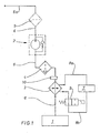
- Fig. 1 shows an excerpt from a circuit diagram for supplying a viscous fuel, in particular rapeseed oil, to a high-pressure pump device of an internal combustion engine.
- the internal combustion engine can only be operated with viscous fuel, but is preferred for starting, stopping and for operation in the low part load range with a low-viscosity fuel, in particular diesel fuel operated.
- the output side is an in Fig. 1 illustrated fuel line section 6a a switching valve provided which promotes the subsidized viscous fuel either via an output line on to the high-pressure pump device or back into a fuel tank 1.
- the low-viscosity fuel is fed via a demand-driven pump via a check valve in the output line of the switching valve.
- the high-pressure pump device is in particular a common-rail system in which two high-pressure pumps convey the fuel into a rail via an input-side quantity control device. From this rail, the individual fuel injection valves controlled by an electronic engine control control the quantity of fuel required in each case and to be injected into the individual combustion chambers. Furthermore, the high-pressure pump system is associated with a leakage line system with a changeover valve, which returns the leakage fuel or discarded fuel in the associated depending on the fuel tank.
- the heat exchanger is valve-controlled by a heat-transmitting cooling medium of the internal combustion engine flows through.
- the cooling system 7 of the internal combustion engine is shown, of which through a coolant supply line 8a, the coolant, which is incidentally in particular cooling water or cooling oil, is passed back to the heat exchanger 3 and from there through a coolant return line 8b back to the cooling system 7 of the internal combustion engine.
- a valve 9 is turned on.
- This valve 9, which is designed as a 2/2-way valve, is switchable between a blocking position, in which the flow connection in the coolant return line 8b is interrupted, and an illustrated passage position.
- the changeover as required is caused by an electronic control unit, which may be part of the aforementioned engine control.
- the fuel temperature determined by a fuel temperature sensor 10 is supplied to this control device, among other parameters, the fuel temperature sensor 10 being inserted directly from the heat exchanger 3 into the fuel line section 6a on the output side.
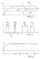
- Part of the control unit is in particular a so-called PI-window controller whose basic operation on the basis of a temperature control according to Fig. 2 is explained.
- the temperature profile 11 is shown, which are adjusted to a temperature setpoint value 12.
- the PI window regulator which has a window 13, which includes the desired value 12 and which is delimited by a positive window boundary 13a and a negative window boundary 13b. Outside this window 13, the PI window regulator controls very hard into the window. In this case, the P component is high and the I component is low. Within the window 13 is controlled slowly and with high accuracy, accordingly, the P component is low and the I component is high.
- Fig. 3 is shown in diagram form the relationship between switching frequency and switching duration.
- the switching frequency 14 of the PI window controller to a value (ts) constant and the switching duration or heating time 15, 15a, 15b, 15c as a change amount set to different values (tx) according to the required heating.
- the PI window controller adjusts the heating time 15, 15a, 15b, 15c as a function of the difference between the actual fuel temperature and the desired value 12. At high difference, the heating time 15c is set very high, while at low difference a low heating time 15b is set. If the target value 12 is approximately reached, an average heating time 15a is set.
- Fig. 4 are summarized the different control processes shown.
- the valve 9 is constantly open and the heat exchanger 3 is constantly flowed through by cooling medium and accordingly corresponds to the heating time 15 of the switching frequency 14.
- the second phase 16b the previously explained Einregelungsvorgang takes place. If the temperature setpoint value 12 is almost reached, the switching frequency 14 is reduced in the phase 16c during the balancing operation also explained above. If the temperature deviates farther from the desired value 12 in a later phase 16 c, the switching frequency is increased again to 5 seconds in order to reduce the temperature difference as quickly as possible.
Landscapes
- Engineering & Computer Science (AREA)
- Chemical & Material Sciences (AREA)
- Combustion & Propulsion (AREA)
- Mechanical Engineering (AREA)
- General Engineering & Computer Science (AREA)
- Oil, Petroleum & Natural Gas (AREA)
- Life Sciences & Earth Sciences (AREA)
- Biodiversity & Conservation Biology (AREA)
- Biotechnology (AREA)
- Botany (AREA)
- Sustainable Development (AREA)
- Sustainable Energy (AREA)
- Feeding And Controlling Fuel (AREA)
- Lubrication Of Internal Combustion Engines (AREA)
Abstract
Description
Die Erfindung betrifft eine Brennkraftmaschine, insbesondere selbstzündende Brennkraftmaschine, die mit einem dickflüssigen Kraftstoff, insbesondere Rapsöl, betreibbar ist, wobei der Kraftstoff aus einem Tank über eine Kraftstoffleitung von einer Förderpumpe über einen Kraftstofffilter in eine Hochdruckpumpeneinrichtung förderbar ist und wobei der Kraftstoff von einer Heizvorrichtung aufheizbar ist sowie ein Verfahren zur Kraftstofftemperaturregelung einer derartigen Brennkraftmaschine.The invention relates to an internal combustion engine, in particular a self-igniting internal combustion engine, which is operable with a viscous fuel, in particular rapeseed oil, wherein the fuel from a tank via a fuel line from a feed pump via a fuel filter in a high-pressure pump device is conveyed and wherein the fuel from a heater heated up is and a method for fuel temperature control of such an internal combustion engine.
Eine solche Brennkraftmaschine ist aus der
Der Erfindung liegt die Aufgabe zugrunde, eine Vorrichtung und ein Verfahren zu einer Kraftstofftemperaturregelung anzugeben, mit dem bei geringem Energieaufwand eine zuverlässige und genaue Temperaturregelung möglich ist.The invention has for its object to provide an apparatus and a method for fuel temperature control, with a reliable and accurate temperature control is possible with low energy consumption.
Diese Aufgabe wird dadurch gelöst, dass die Heizeinrichtung ein in die Kraftstoffleitung eingeschalteter Wärmetauscher ist, der von einem wärmeübertragenden Kühlmedium der Brennkraftmaschine in Abhängigkeit von einem Kraftstofftemperatur-Sollwert und einem Kraftstofftemperatur-Messwert ventilgeregelt durchströmt wird. Zunächst einmal ist dadurch, dass die Heizeinrichtung ein in die Kraftleitung eingeschalteter Wärmetauscher ist, nur die Menge Kraftstoff zu erhitzen, die tatsächlich zur Hochdruckpumpeneinrichtung gefördert wird. Weiterhin steht die Wärmeenergie des Kühlmediums der Brennkraftmaschine als normalerweise über Wärmetauscher abzuführende Energie quasi ohne weiteren Energieaufwand zur Verfügung. Dadurch, dass schließlich der Durchfluss von dem Kühlmedium durch den Wärmetauscher ventilgeregelt durchströmt wird, ist eine einfache und präzise Einstellung eines Temperaturwertes des zu erwärmenden Kraftstoffs möglich.This object is achieved in that the heating device is a heat exchanger which is switched into the fuel line and is flowed through by a heat-transmitting cooling medium of the internal combustion engine as a function of a fuel temperature setpoint and a fuel temperature measurement. First of all, by virtue of the fact that the heating device is a heat exchanger switched into the power line, only the amount of fuel which is actually conveyed to the high-pressure pump device is to be heated. Furthermore, the heat energy of the cooling medium of the internal combustion engine is available as energy normally dissipated via heat exchangers virtually without further energy expenditure. Characterized in that finally the flow of the cooling medium through the heat exchanger is flowed valve regulated, a simple and precise adjustment of a temperature value of the fuel to be heated is possible.
In Weiterbildung der Erfindung ist das Ventil ein 2/2-Wegeventil. Ein solches Ventil ist kostengünstig und zuverlässig und durch die in weiterer Ausgestaltung vorgesehene getaktete Regelung des Ventils ist eine sehr genaue und zuverlässige Einstellung einer Temperatur möglich. Eine genaue Kraftstofftemperaturregelung ist eine entscheidende Komponente für den einwandfreien Betrieb einer mit Rapsöl betriebenen Brennkraftmaschine in den Punkten Leistung, Kraftstoffverbrauch und Emissionen. Das hier angewendete Prinzip für die genaue Kraftstofftemperaturregelung ist eine (langsame) Taktung (offen/geschlossen) des 2/2-Wegeventils, welches den Zustrom des warmen Kühlmediums in den Wärmetauscher regelt. Durch die erfindungsgemäße Ausgestaltung wird eine Ausnutzung der Trägheit der Wärmeabgabe des Wärmetauschers, des Kraftstoffvorfilters, der Kraftstoffpumpe und des Kraftstoffhauptfilters erreicht. Mit der niederfrequenten Taktung des 2/2-Wegeventils werden die einzelnen zuvor genannten Komponenten impulsweise mit aufgeheiztem Rapsöl erwärmt. In der Phase, in der das 2/2-Wegeventil geschlossen ist und folglich das Rapsöl nicht erhitzt wird, wird die in den Komponenten gespeicherte Wärme an das Rapsöl abgegeben. Somit ergibt sich im Mittel eine genau eingeregelte Temperatur an der Hochdruckpumpeneinrichtung. Die Hochdruckpumpeneinrichtung ist insbesondere als Common-Rail-System ausgelegt, wobei insbesondere zwei Hochdruckpumpen den Kraftstoff in ein Rail fördern. Die in das Rail geförderte Kraftstoffmenge wird bestimmt durch eine Kraftstoffzumesseinrichtung, die die den Hochdruckpumpen zugeführte Kraftstoffmenge bestimmt. Die in dieser Kraftstoffzumesseinrichtung herrschende Temperatur wird als Vorgabewert festgelegt. Diese Temperatur soll zwischen 60 °C und 65 °C, bevorzugt 62,5 °C, betragen. In diesem Temperaturbereich ist das Rapsöl genügend dünnflüssig, um problemlos in die einzelnen Brennräume der Brennkraftmaschine eingespritzt zu werden. Andererseits treten bei Temperaturen unterhalb von 65 °C noch (mit einer vorgegebenen geringen Toleranz) keine insbesondere mechanischen oder festigkeitsmäßigen Probleme mit den einzelnen Komponenten (Filtereinsätze usw.) auf. Dagegen würde bei einer grundsätzlich bekannten Zweipunktregelung eine Schwankung von bis zu 15 °C auftreten, die folglich zu Temperaturen bis ca. 80 °C führen würde.In a further development of the invention, the valve is a 2/2-way valve. Such a valve is inexpensive and reliable, and by the clocked control of the valve provided in a further embodiment, a very accurate and reliable setting of a temperature is possible. An accurate fuel temperature control is a crucial component for the proper operation of a rapeseed oil fueled engine in terms of performance, fuel consumption and emissions. The principle used here for the accurate fuel temperature control is a (slow) clocking (open / closed) of the 2/2-way valve, which regulates the flow of warm cooling medium into the heat exchanger. The embodiment according to the invention makes use of the inertia of the heat output of the heat exchanger, the fuel prefilter, the fuel pump and the main fuel filter. With the low-frequency timing of the 2/2-way valve, the individual components mentioned above are heated in pulses with heated rapeseed oil. In the phase in which the 2/2-way valve is closed and consequently the rapeseed oil is not heated, that in the components stored heat is released to the rapeseed oil. Thus, on average, a precisely controlled temperature at the high-pressure pump device results. The high-pressure pump device is designed in particular as a common-rail system, with two high-pressure pumps in particular conveying the fuel into a rail. The amount of fuel delivered to the rail is determined by a fuel metering device that determines the amount of fuel supplied to the high pressure pumps. The prevailing in this fuel metering temperature is set as the default value. This temperature should be between 60 ° C and 65 ° C, preferably 62.5 ° C, amount. In this temperature range, the rapeseed oil is sufficiently thin liquid to be easily injected into the individual combustion chambers of the internal combustion engine. On the other hand, at temperatures below 65 ° C still (with a predetermined low tolerance) no particular mechanical or strength problems with the individual components (filter cartridges, etc.). In contrast, a fluctuation of up to 15 ° C would occur in a basically known two-step control, which would therefore lead to temperatures up to about 80 ° C.
In weiterer Ausgestaltung ist der Regler ein PI-Fensterregler. In einem PI-Fensterregler wird in Abhängigkeit von der Regelabweichung auf verschiedene Verstärkungsfaktoren von dem P-Anteil und dem I-Anteil des Reglers umgeschaltet. Außerhalb des Fensters wird sehr hart und ungenau in das Fenster hinein geregelt, was durch einen hohen P-Anteil und einen geringen I-Anteil des Reglers erreicht wird. Innerhalb des Fensters wird langsam und mit hoher Genauigkeit geregelt, was durch einen niedrigen P-Anteil und einen hohen I-Anteil des Reglers erreicht wird. Hierbei versteht es sich von selbst, dass der Sollwert möglichst genau mittig in dem Fenster liegen soll.In a further embodiment, the controller is a PI window controller. In a PI window controller, depending on the control deviation, different gain factors are switched over from the P-component and the I-component of the controller. Outside the window, it is controlled very hard and inaccurately into the window, which is achieved by a high P-component and a low I-component of the controller. Within the window is controlled slowly and with high accuracy, which is achieved by a low P-component and a high I-component of the controller. It goes without saying that the setpoint should be as central as possible in the window.
In weiterer Ausgestaltung ist der Kraftstofftemperatur-Sollwert in Abhängigkeit von zumindest einer Brennkraftmaschinen-Temperatur korrigierbar. Hierbei erfolgt insbesondere eine Korrektur des Kraftstofftemperatur-Sollwertes in Abhängigkeit von der Ladelufttemperatur und der Kühlmitteltemperatur der Brennkraftmaschine. Aus der ohnehin gemessenen Ladelufttemperatur kann problemlos auf die Umgebungstemperatur geschlossen werden und aus der ebenfalls für den Brennkraftmaschinenbetrieb benötigten Kühlmitteltemperatur wird auf die abgestrahlte Wärmemenge auf die Komponenten Kraftstoffvorfilter, Kraftstoffförderpumpe und Kraftstoffhauptfilter geschlossen. Für diese Korrektur ist also nur ein geringer Aufwand erforderlich.In a further refinement, the fuel temperature setpoint can be corrected as a function of at least one engine temperature. In this case, in particular, a correction of the fuel temperature setpoint takes place as a function of the charge air temperature and the coolant temperature of the internal combustion engine. From the already measured charge air temperature can be easily concluded on the ambient temperature and from the coolant temperature also required for the engine operation is closed to the radiated heat quantity to the components fuel prefilter, fuel pump and main fuel filter. So only a small effort is required for this correction.
In Weiterbildung der Erfindung ist ein Temperaturfühler zur Bestimmung des Kraftstofftemperatur-Messwertes direkt hinter dem Wärmetauscher in der Kraftstoffleitung angeordnet. Mit dieser Anordnung wird ein sehr gutes und genaues Regelungsergebnis erzielt.In a development of the invention, a temperature sensor for determining the fuel temperature measurement value is arranged directly behind the heat exchanger in the fuel line. With this arrangement, a very good and accurate control result is achieved.
In weiterer Ausgestaltung der Erfindung wird der Regelvorgang in einen Einregelvorgang, bei dem die Differenz zwischen dem Kraftstofftemperatur-Sollwert und dem Kraftstofftemperatur-Messwert einen Vorgabewert überschreitet, und einen Ausregelvorgang, bei dem die Differenz zwischen dem Kraftstofftemperatur-Sollwert und dem Kraftstofftemperatur-Messwert den Vorgabewert unterschreitet, aufgeteilt. Durch den solchermaßen aufgeteilten Regelvorgang kann insbesondere eine Schonung des 2/2-Wegeventils erreicht werden. Bei dem Einregelvorgang regelt der PI-Fensterregler das Wegeventil mit einer konstanten hohen Schaltfrequenz und danach, wenn der Vorgabewert erreicht ist, regelt der PI-Fensterregler das Wegeventil in dem Ausregelvorgang mit einer geringen Schaltfrequenz. Bei einer zu großen Abweichung von der Sollwert-Temperatur wird dann in weiterer Ausgestaltung wieder automatisch auf den Einregelvorgang umgeschaltet.In a further embodiment of the invention, the control process is in a Einregelvorgang in which the difference between the fuel temperature setpoint and the fuel temperature reading exceeds a default value, and a Ausregelvorgang, wherein the difference between the fuel temperature setpoint and the fuel temperature reading the default value falls below, split. By thus divided control process, in particular a conservation of the 2/2-way valve can be achieved. During the adjustment process, the PI window regulator regulates the directional control valve at a constant high switching frequency and thereafter, when the default value is reached, the PI window regulator controls the directional control valve in the Ausregelvorgang with a low switching frequency. In the case of too great a deviation from the setpoint temperature, in a further refinement, automatic switching back to the adjustment process takes place.
Wie zuvor ausgeführt ist, wird bevorzugt mit zwei unterschiedlichen Schaltfrequenzen geregelt, wobei jeweils bei einer der beiden Schaltfrequenzen die Schaltdauer variiert wird. Bei einer hohen Differenz zwischen dem Kraftstofftemperatur-Sollwert und dem Kraftstofftemperatur-Messwert wird die Schaltdauer auf einen hohen Wert - entsprechend einer langen Heizzeit - eingestellt, während bei einer geringen Differenz die Schaltdauer und dementsprechend die Heizzeit gering ist. Während des anfänglichen Aufheizens insbesondere bei Inbetriebnahme des Heizsystems wird das Ventil bis zu einem Vorgabewert dauernd geöffnet.As stated above, it is preferred to regulate with two different switching frequencies, the switching duration being varied in each case at one of the two switching frequencies. At a high difference between the fuel temperature setpoint and the fuel temperature measured value, the switching period is set to a high value corresponding to a long heating time, while at a small difference, the switching duration and, accordingly, the heating time is low. During initial heating, in particular when the heating system is put into operation, the valve is opened continuously up to a preset value.
Die dargestellten einzelnen Strategien sind im Übrigen additiv in geeigneter Art und Weise miteinander verknüpft.Incidentally, the illustrated individual strategies are additively linked with one another in a suitable manner.
Weitere vorteilhafte Ausgestaltungen der Erfindung sind der Zeichnungsbeschreibung zu entnehmen, in der ein in den Figuren dargestelltes Ausführungsbeispiel der Erfindung näher beschrieben ist.Further advantageous embodiments of the invention are described in the drawings, in which an illustrated in the figures embodiment of the invention is described in detail.
- Fig. 1Fig. 1
- einen Auszug des Schaltschemas der dickflüssigen Kraftstoffversorgung der Brennkraftmaschine,an extract of the circuit diagram of the viscous fuel supply of the internal combustion engine,
- Fig. 2Fig. 2
- in Diagrammform die Temperatureinregelung in ein Fenster eines PI-Fensterreglers,Diagram shows the temperature regulation in a window of a PI window regulator,
- Fig. 3Fig. 3
- in Diagrammform der Zusammenhang zwischen Schaltfrequenz und Schaltdauer undin diagram form the relationship between switching frequency and switching duration and
- Fig. 4Fig. 4
- in Diagrammform die Aufteilung des Regelvorgangs in unterschiedliche Abschnittein diagram form, the distribution of the control process into different sections
Zurückkommend auf den Schaltkreis gemäß
Der Wärmetauscher ist ventilgeregelt von einem wärmeübertragenden Kühlmedium der Brennkraftmaschine durchströmt. Schematisch ist das Kühlsystem 7 der Brennkraftmaschine dargestellt, von dem durch eine Kühlmittelzuführleitung 8a das Kühlmittel, das im Übrigen insbesondere Kühlwasser oder Kühlöl ist, zu dem Wärmetauscher 3 und von diesem durch eine Kühlmittelrückführleitung 8b wieder zurück zu dem Kühlsystem 7 der Brennkraftmaschine geleitet wird. In die Kühlmittelrückführleitung 8b ist ein Ventil 9 eingeschaltet. Dieses Ventil 9, das als 2/2-Wegeventil ausgebildet ist, ist zwischen einer Sperrstellung, in der die Strömungsverbindung in der Kühlmittelrückführleitung 8b unterbrochen ist, und einer dargestellten Durchlassstellung umschaltbar. Die Umschaltung je nach Erfordernis veranlasst durch ein elektronisches Steuergerät, das Bestandteil der zuvor erwähnten Motorsteuerung sein kann. Diesem Steuergerät wird neben anderen Parametern insbesondere die von einem Kraftstofftemperatursensor 10 ermittelte Kraftstofftemperatur zugeführt, wobei der Kraftstofftemperatursensor 10 direkt ausgangsseitig aus dem Wärmetauscher 3 in den Kraftstoffleitungsabschnitt 6a eingesetzt ist.The heat exchanger is valve-controlled by a heat-transmitting cooling medium of the internal combustion engine flows through. Schematically, the
Bestandteil des Steuergerätes ist insbesondere ein sogenannter PI-Fensterregler, dessen grundsätzliche Arbeitsweise anhand einer Temperatureinregelung gemäß
In
In
Bezugszeichen
- 1
- Kraftstofftank
- 2
- Förderpumpe
- 3
- Wärmetauscher
- 4
- Vorfilter
- 5
- Hauptfilter
- 6, 6a
- Kraftstofffeitungsabschnitt
- 7
- Kühlsystem
- 8a
- Kühlmittelzuführfeitung
- 8b
- Kühlmittelrückführleitung
- 9
- Ventil
- 10
- Kraftstofftemperatursensor
- 11
- Temperaturverlauf
- 12
- Temperatur Soll-Wert
- 13
- Fenster
- 13a
- positive Fenstergrenze
- 13b
- negative Fenstergrenze
- 14
- Schaltfrequenz
- 15 - 15c
- Heizzeit
- 16
- Phase
- 1
- Fuel tank
- 2
- feed pump
- 3
- heat exchangers
- 4
- prefilter
- 5
- main filter
- 6, 6a
- Kraftstofffeitungsabschnitt
- 7
- cooling system
- 8a
- Kühlmittelzuführfeitung
- 8b
- Coolant return line
- 9
- Valve
- 10
- Fuel temperature sensor
- 11
- temperature curve
- 12
- Temperature setpoint
- 13
- window
- 13a
- positive window limit
- 13b
- negative window limit
- 14
- switching frequency
- 15 - 15c
- heating
- 16
- phase
Claims (11)
dadurch gekennzeichnet, dass die Heizeinrichtung ein in die Kraftstoffleitung (6, 6a) eingeschalteter Wärmetauscher (3) ist, der von einem wärmeübertragenden Kühlmedium der Brennkraftmaschine in Abhängigkeit von einem Kraftstofftemperatur-Sollwert (12) und einem Kraftstofftemperatur-Messwert ventilgeregelt durchströmt wird.Internal combustion engine, in particular auto-ignition internal combustion engine, which is operable with a viscous fuel, in particular rapeseed oil, wherein the fuel from a tank via a fuel line from a feed pump via a fuel filter in a high-pressure pump device is conveyed and wherein the fuel is heated by a heater,
characterized in that the heating device is a in the fuel line (6, 6a) switched heat exchanger (3), which is flowed through by a heat-transferring cooling medium of the internal combustion engine in response to a fuel temperature setpoint (12) and a fuel temperature reading valve controlled.
dadurch gekennzeichnet, dass das Ventil (9) ein 2/2-Wegeventil ist.Internal combustion engine according to claim 1,
characterized in that the valve (9) is a 2/2-way valve.
dadurch gekennzeichnet, dass das Ventil (9) getaktet geregelt wird.Internal combustion engine according to one of the preceding claims,
characterized in that the valve (9) is controlled clocked.
dadurch gekennzeichnet, dass der Regler ein PI-Fensterregler ist.Internal combustion engine according to one of the preceding claims,
characterized in that the controller is a PI window controller.
dadurch gekennzeichnet, dass der Kraftstofftemperatur-Sollwert (12) in Abhängigkeit von zumindest einer Brennkraftmaschinentemperatur korrigierbar ist.Internal combustion engine according to one of the preceding claims,
characterized in that the fuel temperature setpoint (12) is correctable in dependence on at least one internal combustion engine temperature.
dadurch gekennzeichnet, dass ein Temperaturfühler (10) zur Bestimmung des Kraftstofftemperatur-Messwertes direkt hinter dem Wärmetauscher (9) in der Kraftstoffleitung (6) angeordnet ist.Internal combustion engine according to one of the preceding claims,
characterized in that a temperature sensor (10) for determining the fuel temperature measurement value is arranged directly behind the heat exchanger (9) in the fuel line (6).
dadurch gekennzeichnet, dass als Heizeinrichtung in die Kraftstoffleitung (6) ein Wärmetauscher (3) eingeschaltet ist, der von einem wärmeübertragenden Kühlmedium der Brennkraftmaschine in Abhängigkeit von einem Kraftstofftemperatur-Sollwert (12) und einem Kraftstofftemperatur-Messwert ventilgeregelt durchströmt wird.Method for fuel temperature control of an internal combustion engine, in particular auto-ignition internal combustion engine, which is operable with a viscous fuel, in particular rapeseed oil, wherein the fuel from a tank via a fuel line from a feed pump via a fuel filter in a high-pressure pump device is conveyed and wherein the fuel from a heater heated up is
characterized in that as a heater in the fuel line (6) a heat exchanger (3) is turned on, which is flowed through by a heat-transferring cooling medium of the internal combustion engine in response to a fuel temperature setpoint (12) and a fuel temperature reading valve controlled.
dadurch gekennzeichnet, dass das als 2/2-Wegeventil ausgebildete Ventil (9) von einem PI-Fensterregler geregelt wird.Method according to claim 7,
characterized in that the designed as a 2/2-way valve valve (9) is controlled by a PI window regulator.
dadurch gekennzeichnet, dass der Regelvorgang in einen Einregelvorgang, bei dem die Differenz zwischen dem Kraftstofftemperatur-Sollwert (12) und dem Kraftstofftemperatur-Messwert einen Vorgabewert überschreitet, und einen Ausregelvorgang, bei dem die Differenz zwischen dem Kraftstofftemperatur-Sollwert und dem Kraftstofftemperatur-Messwert den Vorgabewert unterschreitet, aufgeteilt ist.Method according to claim 7 or 8,
characterized in that the control operation is in a Einregelvorgang in which the difference between the fuel temperature setpoint (12) and the fuel temperature reading exceeds a default value, and a Ausregelvorgang in which the difference between the fuel temperature setpoint and the fuel temperature reading the Default value is less than, divided.
dadurch gekennzeichnet, dass der PI-Fensterreglers während des Einregelungsvorgangs und des Ausregelvorgangs jeweils mit konstanter Schaltfrequenz (14) regelt.Method according to claim 9,
characterized in that the PI window regulator during the Einregelungsvorgangs and the Ausregelvorgangs each with a constant switching frequency (14) controls.
dadurch gekennzeichnet, dass bei konstanter Schaltfrequenz (14) die Schaltdauer variiert wird.Method according to claim 10,
characterized in that at constant switching frequency (14) the switching duration is varied.
Applications Claiming Priority (1)
| Application Number | Priority Date | Filing Date | Title |
|---|---|---|---|
| DE102007039114A DE102007039114A1 (en) | 2007-08-18 | 2007-08-18 | Fuel temperature control by utilizing system inertia |
Publications (2)
| Publication Number | Publication Date |
|---|---|
| EP2028362A2 true EP2028362A2 (en) | 2009-02-25 |
| EP2028362A3 EP2028362A3 (en) | 2012-01-11 |
Family
ID=39791157
Family Applications (1)
| Application Number | Title | Priority Date | Filing Date |
|---|---|---|---|
| EP08014585A Withdrawn EP2028362A3 (en) | 2007-08-18 | 2008-08-15 | Fuel temperature control by exploiting system inactivity |
Country Status (2)
| Country | Link |
|---|---|
| EP (1) | EP2028362A3 (en) |
| DE (1) | DE102007039114A1 (en) |
Cited By (2)
| Publication number | Priority date | Publication date | Assignee | Title |
|---|---|---|---|---|
| DE102012015454A1 (en) | 2012-08-03 | 2014-05-28 | Rolls-Royce Deutschland Ltd & Co Kg | Method for controlling the fuel temperature of a gas turbine |
| EP3228851A4 (en) * | 2014-12-05 | 2018-07-18 | Hitachi Automotive Systems, Ltd. | Control device for internal combustion engine |
Families Citing this family (2)
| Publication number | Priority date | Publication date | Assignee | Title |
|---|---|---|---|---|
| RU2537650C2 (en) * | 2012-06-13 | 2015-01-10 | Федеральное государственное бюджетное образовательное учреждение высшего профессионального образования "Воронежский государственный аграрный университет имени императора Петра 1" (ФГБОУ ВПО Воронежский ГАУ) | Supply system of internal-combustion engine |
| CN103742305A (en) * | 2013-12-26 | 2014-04-23 | 内蒙古北方重型汽车股份有限公司 | Fuel heating system of mining dump truck |
Citations (1)
| Publication number | Priority date | Publication date | Assignee | Title |
|---|---|---|---|---|
| DE3800585A1 (en) | 1987-01-13 | 1988-07-28 | Kloeckner Humboldt Deutz Ag | Device for the alternative operation of a diesel internal combustion engine with diesel oil and rape seed oil |
Family Cites Families (11)
| Publication number | Priority date | Publication date | Assignee | Title |
|---|---|---|---|---|
| US3834617A (en) * | 1973-05-14 | 1974-09-10 | Landis & Gyr Ag | Pid controller for heating, ventilating and air conditioning systems |
| CA1084367A (en) * | 1978-01-18 | 1980-08-26 | Kevin J. Elliott | Fuel heating device for internal combustion engines |
| DE3149603A1 (en) * | 1981-12-15 | 1983-07-21 | Werner Emil 6800 Mannheim Bausch | Method for the operation of internal combustion engines, especially of diesel engines and combustion engine system |
| FR2579679B1 (en) * | 1985-03-27 | 1989-05-19 | Minoux Jean Pierre | METHOD AND DEVICE FOR PREHEATING THE LIQUID FUEL OF A DIESEL ENGINE |
| DE4108035A1 (en) * | 1991-03-13 | 1992-09-17 | Man Technologie Gmbh | FUEL VALVE |
| US5218944A (en) * | 1992-10-26 | 1993-06-15 | Leonard Paul D | Fuel preheating system for internal combustion engines |
| US5443053A (en) * | 1993-07-27 | 1995-08-22 | Johnson; Jack E. | Fuel heater |
| US5848640A (en) * | 1996-09-27 | 1998-12-15 | Ford Global Technologies, Inc. | Apparatus for controlling the temperature of fuel in a motor vehicle fuel tank |
| US5778861A (en) * | 1997-02-10 | 1998-07-14 | Victor J. Diduck | Apparatus and method for controlling the temperature of a fluid |
| AT7373U1 (en) * | 2004-10-07 | 2005-02-25 | Karl Wurzer | BUILT-IN DEVICE TO REDUCE DAMAGE TO THE FOAM, TO REDUCE NOISE, INCREASE PERFORMANCE AND MONITOR THE FUEL CONSUMPTION OF DIESEL ENGINES |
| DE202007000681U1 (en) * | 2007-01-11 | 2007-03-22 | Sellentin, Alexander | Fuel supply device for a diesel engine, with reversible or disconnectable heat exchanger in front of the injection pump |
-
2007
- 2007-08-18 DE DE102007039114A patent/DE102007039114A1/en not_active Withdrawn
-
2008
- 2008-08-15 EP EP08014585A patent/EP2028362A3/en not_active Withdrawn
Patent Citations (1)
| Publication number | Priority date | Publication date | Assignee | Title |
|---|---|---|---|---|
| DE3800585A1 (en) | 1987-01-13 | 1988-07-28 | Kloeckner Humboldt Deutz Ag | Device for the alternative operation of a diesel internal combustion engine with diesel oil and rape seed oil |
Cited By (3)
| Publication number | Priority date | Publication date | Assignee | Title |
|---|---|---|---|---|
| DE102012015454A1 (en) | 2012-08-03 | 2014-05-28 | Rolls-Royce Deutschland Ltd & Co Kg | Method for controlling the fuel temperature of a gas turbine |
| EP3228851A4 (en) * | 2014-12-05 | 2018-07-18 | Hitachi Automotive Systems, Ltd. | Control device for internal combustion engine |
| US10309337B2 (en) | 2014-12-05 | 2019-06-04 | Hitachi Automotive Systems, Ltd. | Control device for internal combustion engine |
Also Published As
| Publication number | Publication date |
|---|---|
| EP2028362A3 (en) | 2012-01-11 |
| DE102007039114A1 (en) | 2009-02-19 |
Similar Documents
| Publication | Publication Date | Title |
|---|---|---|
| DE102013213506B4 (en) | Method for operating a fuel injection system with a fuel filter heater and fuel injection system | |
| DE2715587A1 (en) | FUEL SUPPLY DEVICE | |
| EP2212541A1 (en) | Method and device for controlling a fuel supply system | |
| DE102010064176A1 (en) | Fuel supply system for an internal combustion engine | |
| EP0925434B1 (en) | System for operating an internal combustion engine, in particular of a motor vehicle | |
| EP2028362A2 (en) | Fuel temperature control by exploiting system inactivity | |
| DE19913477A1 (en) | Operating fuel delivery device for internal combustion engine, especially for motor vehicle, involves influencing quantity control valve by battery voltage and/or depending on coil resistance | |
| EP2080888B1 (en) | Automatic fuel detection | |
| DE10137315A1 (en) | Circuit layout for controlling an electric fuel pump has an electric fuel pump in a fuel tank to feed fuel to a high-pressure pump linked to fuel injection valves and a signal-controlled motorized control for delivery power | |
| DE10036772C2 (en) | Method for operating a fuel metering system of a direct injection internal combustion engine | |
| DE4443836A1 (en) | Combustion engine fuel supply appts. | |
| DE102010031570B4 (en) | Method for determining a characteristic for a pressure control valve | |
| DE102011004514A1 (en) | Method and control unit for setting a temperature of a glow plug | |
| DE19916101A1 (en) | Control method for IC engine with common-rail fuel injection system switches between two different fuel pressure regulators dependent on difference between required and actual pressure of fuel reservoir | |
| DE102013220419A1 (en) | Method and device for controlling an internal combustion engine with high-pressure injection | |
| DE102015114716A1 (en) | Fuel injector with two fuel inlets | |
| WO2012089367A1 (en) | Fuel supply system for an internal combustion engine having a fule pump | |
| DE10046113A1 (en) | Unit producing emulsion of water in heavy oil for diesel engine or heating plant, includes heaters in oil and supply lines, to reach predetermined temperature | |
| DE102006000321A1 (en) | Storage fuel injection system for engine has store, fuel injection valve, intended pressure setting device and pressure variation sensing mechanism | |
| DE102009029596B4 (en) | Method for controlling an internal combustion engine | |
| DE102010031002B4 (en) | Method for controlling the pressure in a high-pressure fuel accumulator of an internal combustion engine | |
| DE102007013772B4 (en) | Method for controlling an injection system of an internal combustion engine | |
| DE10329563B9 (en) | Method and device for the needs-based cooling of internal combustion engines using a bypass valve and at least one heat sink | |
| EP2825764B1 (en) | Fuel delivery device, and method for actuating a fuel delivery device | |
| DE10200795A1 (en) | Method, computer program, control and / or regulating device for operating a fuel system of an internal combustion engine, and internal combustion engine |
Legal Events
| Date | Code | Title | Description |
|---|---|---|---|
| PUAI | Public reference made under article 153(3) epc to a published international application that has entered the european phase |
Free format text: ORIGINAL CODE: 0009012 |
|
| AK | Designated contracting states |
Kind code of ref document: A2 Designated state(s): AT BE BG CH CY CZ DE DK EE ES FI FR GB GR HR HU IE IS IT LI LT LU LV MC MT NL NO PL PT RO SE SI SK TR |
|
| AX | Request for extension of the european patent |
Extension state: AL BA MK RS |
|
| PUAL | Search report despatched |
Free format text: ORIGINAL CODE: 0009013 |
|
| AK | Designated contracting states |
Kind code of ref document: A3 Designated state(s): AT BE BG CH CY CZ DE DK EE ES FI FR GB GR HR HU IE IS IT LI LT LU LV MC MT NL NO PL PT RO SE SI SK TR |
|
| AX | Request for extension of the european patent |
Extension state: AL BA MK RS |
|
| RIC1 | Information provided on ipc code assigned before grant |
Ipc: G05D 23/19 20060101ALI20111205BHEP Ipc: F02M 31/16 20060101AFI20111205BHEP |
|
| 17P | Request for examination filed |
Effective date: 20120621 |
|
| AKX | Designation fees paid |
Designated state(s): AT BE BG CH CY CZ DE DK EE ES FI FR GB GR HR HU IE IS IT LI LT LU LV MC MT NL NO PL PT RO SE SI SK TR |
|
| STAA | Information on the status of an ep patent application or granted ep patent |
Free format text: STATUS: THE APPLICATION IS DEEMED TO BE WITHDRAWN |
|
| 18D | Application deemed to be withdrawn |
Effective date: 20150303 |