EP2028349A1 - Oil sensor placement structure of engine - Google Patents
Oil sensor placement structure of engine Download PDFInfo
- Publication number
- EP2028349A1 EP2028349A1 EP07741420A EP07741420A EP2028349A1 EP 2028349 A1 EP2028349 A1 EP 2028349A1 EP 07741420 A EP07741420 A EP 07741420A EP 07741420 A EP07741420 A EP 07741420A EP 2028349 A1 EP2028349 A1 EP 2028349A1
- Authority
- EP
- European Patent Office
- Prior art keywords
- oil
- engine
- balancer
- housing
- oil sensor
- Prior art date
- Legal status (The legal status is an assumption and is not a legal conclusion. Google has not performed a legal analysis and makes no representation as to the accuracy of the status listed.)
- Granted
Links
Images




Classifications
-
- F—MECHANICAL ENGINEERING; LIGHTING; HEATING; WEAPONS; BLASTING
- F01—MACHINES OR ENGINES IN GENERAL; ENGINE PLANTS IN GENERAL; STEAM ENGINES
- F01M—LUBRICATING OF MACHINES OR ENGINES IN GENERAL; LUBRICATING INTERNAL COMBUSTION ENGINES; CRANKCASE VENTILATING
- F01M11/00—Component parts, details or accessories, not provided for in, or of interest apart from, groups F01M1/00 - F01M9/00
- F01M11/10—Indicating devices; Other safety devices
- F01M11/12—Indicating devices; Other safety devices concerning lubricant level
-
- F—MECHANICAL ENGINEERING; LIGHTING; HEATING; WEAPONS; BLASTING
- F02—COMBUSTION ENGINES; HOT-GAS OR COMBUSTION-PRODUCT ENGINE PLANTS
- F02B—INTERNAL-COMBUSTION PISTON ENGINES; COMBUSTION ENGINES IN GENERAL
- F02B75/00—Other engines
- F02B75/06—Engines with means for equalising torque
Definitions
- the present invention relates to an oil sensor placement structure in an engine that includes a balancer housing for housing a mutually parallel pair of balancer shafts between a lower face of a cylinder block and an oil pan storing engine oil.
- an oil deterioration sensor for detecting the degree of deterioration of engine oil based on the pH value is provided in a bottom part of an oil pan.
- This oil deterioration sensor includes a sensing part housing a sensing element in the interior and a mounting part supporting the sensing part, and the mounting part is fixed to the bottom part of the oil pan by inserting the sensing part upwardly from an opening formed in the bottom part of the oil pan.
- Patent Publication 2 Japanese Patent Application Laid-open No. 2003-83935
- Patent Publication 2 Japanese Patent Application Laid-open No. 11-30115
- the conventional oil deterioration sensor is formed from the sensing part, which is housed within the oil pan, and the mounting part, which is exposed on the outside of the oil pan; an oil hole for engine oil to enter and exit is formed in the vicinity of a lower end part of the sensing part, and a breather hole for air to enter and exit is formed in the vicinity of an upper end part of the sensing part. Because of this, when engine oil within the oil pan is disturbed and the splashes thus produced enter the sensing part via the breather hole, there is a possibility that the liquid level of the engine oil within the sensing part will change and affect the detection precision.
- the present invention has been accomplished in the light of the above-mentioned circumstances, and it is an object thereof to place an oil sensor by utilizing dead space within an oil pan effectively while guaranteeing the detection precision of the oil sensor.
- an oil sensor placement structure in an engine comprising a balancer housing for housing a mutually parallel pair of balancer shafts between a lower face of a cylinder block and an oil pan storing engine oil, the structure being characterized in that an oil sensor provided in a bottom part of the oil pan so as to stand vertically upright is placed between the pair of balancer shafts.
- an oil sensor placement structure in an engine comprising a balancer housing for housing a mutually parallel pair of balancer shafts between a lower face of a cylinder block and an oil pan storing engine oil, the structure being characterized in that an oil sensor provided in a bottom part of the oil pan so as to stand vertically upright is placed so as to project into the interior of the balancer housing.
- an exhaust gas passage through which exhaust gas flows is placed beneath the oil pan, and the oil sensor is placed at a position where the oil sensor does not overlap with the exhaust gas passage when viewed vertically.
- a bottom part of the oil pan comprises a shallow bottom part and a deep bottom part having different depths, the exhaust gas passage through which exhaust gas flows is placed beneath the shallow bottom part, and the oil sensor is placed above the deep bottom part.
- the oil sensor comprises a cover member covering a sensing element, and a breather hole formed in the vicinity of the upper end of the cover member is covered by a shielding part provided on the balancer housing.
- the shielding part surrounds at least an upper half of a portion of the oil sensor exposed within the oil pan.
- the shielding part is formed as a separate body from the balancer housing and is mounted on the balancer housing.
- an air vent hole providing communication between the interior and exterior of the shielding part is formed at a position of the shielding part that is higher than the breather hole.
- an air vent hole providing communication between the interior and exterior of the shielding part is formed at a position of the shielding part that does not face the opening direction of the breather hole.
- An exhaust pipe 18 of an embodiment corresponds to the exhaust gas passage of the present invention
- a driven balancer shaft 27 and a follower balancer shaft 28 of the embodiment correspond to the balancer shaft of the present invention
- an oil level sensor 47 of the embodiment corresponds to the oil sensor of the present invention.
- the oil sensor which is provided in the bottom part of the oil pan storing engine oil so as to stand vertically upright, is placed between the pair of balancer shafts, which are housed within the balancer housing so as to be parallel to each other, not only can the oil sensor be placed compactly by utilizing effectively the dead space formed between the pair of balancer shafts, but it is also possible to make the pair of balancer shafts exhibit the function of a baffle plate for suppressing agitation of the engine oil, thereby preventing engine oil from splashing over the oil sensor and degrading the detection precision.
- the oil sensor which is provided in the bottom part of the oil pan storing engine oil so as to stand vertically upright, is placed within the balancer housing so as to project therefrom, not only can the oil sensor be placed compactly by utilizing effectively the dead space formed in the interior of the balancer housing, but it is also possible to make the balancer housing exhibit the function of a baffle plate for suppressing agitation of the oil liquid surface, thereby preventing engine oil from splashing over the oil sensor and degrading the detection precision.
- the oil sensor and the exhaust gas passage provided beneath the oil pan are placed at positions where they do not overlap each other when viewed from the vertical direction, it is possible to guarantee a distance between the oil sensor and the exhaust gas passage, which attains a high temperature, thus preventing degradation of the detection precision of the oil sensor due to heat.
- the exhaust gas passage is placed beneath the shallow bottom part, the oil sensor is placed above the deep bottom part, and it is therefore possible to place the oil sensor by utilizing a space above the deep bottom part even if it is difficult to guarantee a space for placing the oil sensor above the shallow bottom part.
- the breather hole which is formed in the vicinity of the upper end of the cover member covering the sensing element of the oil sensor, is covered with the shielding part provided on the balancer housing, and it is therefore possible by means of the shielding part to suppress the entrance of splashes of engine oil generated within the oil pan into the sensing part via the breather hole of the cover member, thus further enhancing the detection precision of the oil sensor.
- At least an upper half is surrounded by the shielding part, and it is therefore possible to reliably prevent splashes of engine oil from entering via the breather hole formed in the vicinity of the upper end of the cover member of the oil sensor.
- the shielding part is formed separately from the balancer housing and mounted on the balancer housing, and it is therefore easy to mold the balancer housing compared with a case in which the shielding part is molded integrally with the balancer housing, thus enhancing the degree of freedom in design of the shielding part.
- the air vent hole which provides communication between the interior and the exterior of the shielding part, is formed at a position of the shielding part that is higher than the breather hole, and it is therefore possible to keep the internal pressure of the shielding part constant, thus guaranteeing the detection precision of the oil sensor.
- the air vent hole which provides communication between the interior and the exterior of the shielding part, is formed at a position of the shielding part that does not face the opening direction of the breather hole, and it is therefore possible to increase the degree of freedom in design of the position of the air vent hole and thus enhance the oil shielding effect while guaranteeing the detection precision of the oil sensor by keeping the internal pressure of the shielding part constant.
- FIG. 1 to FIG. 8 show a first embodiment of the present invention.
- a diesel engine E transversely mounted in an engine compartment of an automobile has a cylinder block 11, a cylinder head 12 and head cover 13 joined to an upper part thereof, and a crankcase 14 and oil pan 15 joined to a lower part thereof.
- An exhaust pipe 18 connected via a DPF (Diesel Particulate Filter) 17 to an exhaust manifold 16 joined to a front face of the cylinder head 12 extends to the rear of a vehicle body via a lower face of the oil pan 15.
- a secondary balancer system 19 that reduces secondary vibration of the engine E is provided between the lower face of the cylinder block 11 and the oil pan 15.
- a crankshaft 20 is rotatably supported on mating faces of the cylinder block 11 and the crankcase 14.
- a balancer housing 21 of the secondary balancer system 19 is formed by joining an upper housing 22 and a lower housing 23 via a plurality of bolts 24, and further joining a side housing 25 to a right side face of the lower housing 23 via a plurality of bolts 26, and a driven balancer shaft 27 and a follower balancer shaft 28 are supported therewithin in parallel to the crankshaft 20.
- the balancer housing 21 is fixed to a lower face of the crankcase 14 via two bolts 29 and 29 running through the upper housing 22 and the lower housing 23 from bottom to top and two bolts 30 and 30 running through the side housing 25 from bottom to top.
- Openings 61 and 62 are formed in an upper face of the upper housing 22, an opening 63 is formed in mating faces of the upper housing 22 and the lower housing 23, and an opening 64 is formed between the upper housing 22 and the side housing 25.
- the interior of the balancer housing 21 communicates with the interior of the oil pan 15 via these openings 61, 62, 63, and 64.
- a driven balancer shaft 27 positioned on the rear side of the vehicle body are, going from one end to the other end, a driven sprocket 31, a driven gear 32, a first balancer weight 33, and a second balancer weight 34.
- a follower balancer shaft 28 positioned on the front side of the vehicle body are, going from one end to the other end, a follower gear 35, a first balancer weight 36, and a second balancer weight 37.
- An endless chain 39 (see FIG. 1 and FIG. 2 ) is wrapped around a drive sprocket 38 (see FIG. 1 ) provided on the crankshaft 20 and the driven sprocket 31 provided on the driven balancer shaft 27.
- the driven gear 32 provided on the driven balancer shaft 27 meshes with the follower gear 35 provided on the follower balancer shaft 28.
- Rotation of the crankshaft 20 due to the engine E running is transmitted to the driven balancer shaft 27 via the drive sprocket 38, the endless chain 39, and the driven sprocket 31, and rotation of the driven balancer shaft 27 is transmitted to the follower balancer shaft 28 via the driven gear 32 and the follower gear 35.
- the driven balancer shaft 27 and the follower balancer shaft 28 rotate in directions opposite to each other at a rotational speed twice the rotational speed of the crankshaft 20, and secondary vibration of the engine E is suppressed by the first and second balancer weights 33, 36; 34, 37 provided on the driven balancer shaft 27 and the follower balancer shaft 28.
- a trochoidal type oil pump 43 having an inner rotor 42 meshing with an outer rotor 41 is housed in a recess 40 formed in a mating face of the lower housing 23 via which it is joined to the side housing 25.
- a pump shaft 44 fixed to the inner rotor 42 is joined to the follower balancer shaft 28 placed coaxially therewith via a coupling 45.
- a filter 46 for filtering oil taken into the oil pump 43 is housed in a bottom part of the lower housing 23.
- a bottom part on the vehicle body left-hand side (right-hand side in the figure) is a shallow bottom part 15a that is stepped shallower, and the remaining part is a deep bottom part 15b that is deeper than the shallow bottom part 15a.
- the shallow bottom part 15a is provided at a position where it does not interfere with the secondary balancer system 19, and the exhaust pipe 18 is placed by utilizing a space formed beneath the shallow bottom part 15a.
- an oil level sensor 47 for detecting the oil level within the oil pan 15 includes a plate-shaped mounting part 48 and a tower-shaped sensing part 49 extending upward from the center of the mounting part 48.
- An opening 15d is formed in the center of a recess 15c formed by recessing upward the deep bottom part 15b of the oil pan 15, and with regard to the oil level sensor 47, in a state in which the sensing part 49 is inserted into the oil pan 15 via the opening 15d, the mounting part 48 is fixed to the recess 15c around the opening 15d via a seal member 50 by means of three bolts 51.
- a plate-shaped cover member 52 is fixed to the recess 15c of the oil pan 15 via a plurality of bolts 53.
- the sensing part 49 of the oil level sensor 47 includes a hollow cover member 54; a transversely long slit-shaped oil hole 54a communicating with engine oil within the oil pan 15 is formed at the lower end of the cover member 54, and a breather hole 54b communicating with air within the balancer housing 21 is formed at the upper end of the cover member 54. Therefore, the oil level within the cover member 54 of the sensing part 49 moves up and down so as to coincide with the oil level within the balancer housing 21 (that is, the oil level within the oil pan 15).
- a plate-shaped sensing element 55 is placed in the interior of the cover member 54 of the sensing part 49 of the oil level sensor 47. After the sensing element 55 is heated to a temperature that is higher than the oil temperature by, for example, 10°C by passing current through the sensing element 55 so as to generate heat, the time taken for the temperature to decrease by, for example, 5°C is measured.
- the oil level is high, heat radiation from the sensing element 55 to the engine oil is promoted and the temperature decreases quickly, whereas when the oil level is low, heat radiation from the sensing element 55 to the engine oil is suppressed and the temperature decreases slowly, thus enabling the oil level within the oil pan 15 to be detected.
- the upper housing 22 and the side housing 25 are not in intimate contact with each other but are spaced from each other, and in that portion the balancer housing 21 opens widely via the opening 64.
- An opening 65 is formed in the lower housing 23 positioned beneath the opening 64, the sensing part 49 of the oil level sensor 47 passes through the opening 65 of the lower housing 23 from bottom to top, and projects between the driven balancer shaft 27 and the follower balancer shaft 28 within the balancer housing 21.
- the shielding part 56 projects from the upper housing 22 toward the opening 64 of the balancer housing 21.
- the shielding part 56 is an inverted cup-shaped member having its lower face open, and the shielding part 56 covers an upper end part of the sensing part 49 of the oil level sensor 47.
- An air vent hole 56a is formed in an upper face of the shielding part 56 at a position higher than the breather hole 54b of the sensing part 49 of the oil level sensor 47.
- the detection precision of the oil level sensor 47 deteriorates, but in the interior of the balancer housing 21, in particular a space between the driven balancer shaft 27 and the follower balancer shaft 28 supported on the interior of the balancer housing 21, variation of the oil level is smoothed and becomes small. Therefore, placing the sensing part 49 of the oil level sensor 47 in the space between the driven balancer shaft 27 and the follower balancer shaft 28 within the balancer housing 21 enables variation of the oil level to be minimized and the detection precision to be enhanced without providing a special baffle plate.
- the exhaust pipe 18 and the oil level sensor 47 are placed so as not to overlap each other in plan view. This placement ensures that there is a distance between the high temperature exhaust pipe 18 and the oil level sensor 47, which is susceptible to heat, thus preventing the detection precision of the oil level sensor 47 from deteriorating due to heat.
- the shielding part 56 is integrated with the upper housing 22 of the balancer housing 21, the number of components can be reduced compared with a case in which the shielding part 56 is formed from an independent component.
- the air vent hole 56a is formed in the upper face of the shielding part 56, it is possible by means of the air vent hole 56a to prevent air from being sealed in the internal space and to avoid any degradation in the detection precision of the oil level sensor 47. Furthermore, since the air vent hole 56a opens vertically and the breather hole 54b opens horizontally, it is possible to suppress the possibility of engine oil splashing through both the air vent hole 56a and the breather hole 54b and entering the cover member 54.
- the air vent hole 56a of the shielding part 56 is provided at a position higher than the breather hole 54b of the sensing part 49, but as long as it is a position that does not face the opening direction of the breather hole 54b (preferably a position displaced by 180°), the same effects can be obtained by providing the air vent hole 56a at a position lower than the breather hole 54b. Due to this layout, the degree of freedom in the position at which the air vent hole 56a is provided increases, it becomes possible to open the air vent hole 56a horizontally, and it is possible to prevent any degradation in the detection precision of the oil level sensor 47 due to oil scattering within the oil pan 15 or oil dripping from above.
- a second embodiment of the present invention is explained by reference to FIG. 9 .
- the shielding part 56 is formed integrally with the upper housing 22, but a shielding part 56 of the second embodiment is formed as an independent member, and is mounted on a lower face of an opening 65 of a lower housing 23 of a balancer housing 21 via bolts 57 and 57.
- the shielding part 56 is a tapered tubular member tapering from a lower part to an upper part, and covers substantially the whole of a sensing part 49 of an oil level sensor 47 projecting into an oil pan 15.
- the oil level sensor 47 for detecting the level of engine oil is explained, but the present invention may be applied to any other oil sensor for detecting the temperature or the degree of deterioration of engine oil.
- the shielding part 56 covers substantially the whole of the sensing part 49 of the oil level sensor 47, but an operational effect comparable to that of the case where the whole is covered can be obtained by covering at least the upper half of the sensing part 49.
Landscapes
- Engineering & Computer Science (AREA)
- Mechanical Engineering (AREA)
- General Engineering & Computer Science (AREA)
- Chemical & Material Sciences (AREA)
- Combustion & Propulsion (AREA)
- Lubrication Details And Ventilation Of Internal Combustion Engines (AREA)
Abstract
Description
- The present invention relates to an oil sensor placement structure in an engine that includes a balancer housing for housing a mutually parallel pair of balancer shafts between a lower face of a cylinder block and an oil pan storing engine oil.
- An arrangement in which, in order to determine the timing of changing engine oil of an automobile engine, an oil deterioration sensor for detecting the degree of deterioration of engine oil based on the pH value is provided in a bottom part of an oil pan is known from Patent Publication 1 below. This oil deterioration sensor includes a sensing part housing a sensing element in the interior and a mounting part supporting the sensing part, and the mounting part is fixed to the bottom part of the oil pan by inserting the sensing part upwardly from an opening formed in the bottom part of the oil pan.
- Furthermore, an arrangement in which, in order to suppress disturbance of the liquid surface of engine oil stored in the interior of an engine oil pan, a baffle plate is provided above the engine oil is known from Patent Publication 2 below.
Patent Publication 1: Japanese Patent Application Laid-open No.2003-83935
Patent Publication 2: Japanese Patent Application Laid-open No.11-30115 - The conventional oil deterioration sensor is formed from the sensing part, which is housed within the oil pan, and the mounting part, which is exposed on the outside of the oil pan; an oil hole for engine oil to enter and exit is formed in the vicinity of a lower end part of the sensing part, and a breather hole for air to enter and exit is formed in the vicinity of an upper end part of the sensing part. Because of this, when engine oil within the oil pan is disturbed and the splashes thus produced enter the sensing part via the breather hole, there is a possibility that the liquid level of the engine oil within the sensing part will change and affect the detection precision.
- In order to prevent the engine oil from being disturbed, placing a baffle plate within the oil pan is effective, but providing a baffle plate gives rise to the problem of an increase in the number of components. Furthermore, when an exhaust pipe extending forward from a cylinder head of a transversely mounted engine is guided to the rear of a vehicle body by bending the exhaust pipe downward and rearward and passing it beneath the oil pan, it is necessary to guarantee a minimum ground clearance for the exhaust pipe by placing the exhaust pipe within an upward recess formed in the bottom part of the oil pan. When a balancer system is placed within the oil pan, if the recess for the exhaust pipe to pass through is formed in the oil pan, there is a possibility that due to the recess it will become difficult to guarantee a space for placing the oil sensor within the oil pan.
- The present invention has been accomplished in the light of the above-mentioned circumstances, and it is an object thereof to place an oil sensor by utilizing dead space within an oil pan effectively while guaranteeing the detection precision of the oil sensor.
- In order to attain the above object, according to a first aspect of the present invention, there is proposed an oil sensor placement structure in an engine, the engine comprising a balancer housing for housing a mutually parallel pair of balancer shafts between a lower face of a cylinder block and an oil pan storing engine oil, the structure being characterized in that an oil sensor provided in a bottom part of the oil pan so as to stand vertically upright is placed between the pair of balancer shafts.
- According to a second aspect of the present invention, there is proposed an oil sensor placement structure in an engine, the engine comprising a balancer housing for housing a mutually parallel pair of balancer shafts between a lower face of a cylinder block and an oil pan storing engine oil, the structure being characterized in that an oil sensor provided in a bottom part of the oil pan so as to stand vertically upright is placed so as to project into the interior of the balancer housing.
- According to a third aspect of the present invention, in addition to the first or second aspect, an exhaust gas passage through which exhaust gas flows is placed beneath the oil pan, and the oil sensor is placed at a position where the oil sensor does not overlap with the exhaust gas passage when viewed vertically.
- According to a fourth aspect of the present invention, in addition to the first or second aspect, a bottom part of the oil pan comprises a shallow bottom part and a deep bottom part having different depths, the exhaust gas passage through which exhaust gas flows is placed beneath the shallow bottom part, and the oil sensor is placed above the deep bottom part.
- According to a fifth aspect of the present invention, in addition to any one of the first to fourth aspects, the oil sensor comprises a cover member covering a sensing element, and a breather hole formed in the vicinity of the upper end of the cover member is covered by a shielding part provided on the balancer housing.
- According to a sixth aspect of the present invention, in addition to the fifth aspect, the shielding part surrounds at least an upper half of a portion of the oil sensor exposed within the oil pan.
- According to a seventh aspect of the present invention, in addition to the fifth or sixth aspect, the shielding part is formed as a separate body from the balancer housing and is mounted on the balancer housing.
- According to an eighth aspect of the present invention, in addition to any one of the fifth to seventh aspects, an air vent hole providing communication between the interior and exterior of the shielding part is formed at a position of the shielding part that is higher than the breather hole.
- According to a ninth aspect of the present invention, in addition to any one of the fifth to seventh aspects, an air vent hole providing communication between the interior and exterior of the shielding part is formed at a position of the shielding part that does not face the opening direction of the breather hole.
- An
exhaust pipe 18 of an embodiment corresponds to the exhaust gas passage of the present invention, a drivenbalancer shaft 27 and afollower balancer shaft 28 of the embodiment correspond to the balancer shaft of the present invention, and anoil level sensor 47 of the embodiment corresponds to the oil sensor of the present invention. - In accordance with a first aspect of the present invention, since the oil sensor, which is provided in the bottom part of the oil pan storing engine oil so as to stand vertically upright, is placed between the pair of balancer shafts, which are housed within the balancer housing so as to be parallel to each other, not only can the oil sensor be placed compactly by utilizing effectively the dead space formed between the pair of balancer shafts, but it is also possible to make the pair of balancer shafts exhibit the function of a baffle plate for suppressing agitation of the engine oil, thereby preventing engine oil from splashing over the oil sensor and degrading the detection precision.
- Furthermore, in accordance with the second aspect of the present invention, since the oil sensor, which is provided in the bottom part of the oil pan storing engine oil so as to stand vertically upright, is placed within the balancer housing so as to project therefrom, not only can the oil sensor be placed compactly by utilizing effectively the dead space formed in the interior of the balancer housing, but it is also possible to make the balancer housing exhibit the function of a baffle plate for suppressing agitation of the oil liquid surface, thereby preventing engine oil from splashing over the oil sensor and degrading the detection precision.
- Moreover, in accordance with the third aspect of the present invention, since the oil sensor and the exhaust gas passage provided beneath the oil pan are placed at positions where they do not overlap each other when viewed from the vertical direction, it is possible to guarantee a distance between the oil sensor and the exhaust gas passage, which attains a high temperature, thus preventing degradation of the detection precision of the oil sensor due to heat.
- Furthermore, in accordance with the fourth aspect of the present invention, among the shallow bottom part and the deep bottom part of the bottom part of the oil pan, the exhaust gas passage is placed beneath the shallow bottom part, the oil sensor is placed above the deep bottom part, and it is therefore possible to place the oil sensor by utilizing a space above the deep bottom part even if it is difficult to guarantee a space for placing the oil sensor above the shallow bottom part.
- Moreover, in accordance with the fifth aspect of the present invention, the breather hole, which is formed in the vicinity of the upper end of the cover member covering the sensing element of the oil sensor, is covered with the shielding part provided on the balancer housing, and it is therefore possible by means of the shielding part to suppress the entrance of splashes of engine oil generated within the oil pan into the sensing part via the breather hole of the cover member, thus further enhancing the detection precision of the oil sensor.
- Furthermore, in accordance with the sixth aspect of the present invention, of a portion of the oil sensor that is exposed within the oil pan, at least an upper half is surrounded by the shielding part, and it is therefore possible to reliably prevent splashes of engine oil from entering via the breather hole formed in the vicinity of the upper end of the cover member of the oil sensor.
- Moreover, in accordance with the seventh aspect of the present invention, the shielding part is formed separately from the balancer housing and mounted on the balancer housing, and it is therefore easy to mold the balancer housing compared with a case in which the shielding part is molded integrally with the balancer housing, thus enhancing the degree of freedom in design of the shielding part.
- Furthermore, in accordance with the eighth aspect of the present invention, the air vent hole, which provides communication between the interior and the exterior of the shielding part, is formed at a position of the shielding part that is higher than the breather hole, and it is therefore possible to keep the internal pressure of the shielding part constant, thus guaranteeing the detection precision of the oil sensor.
- Moreover, in accordance with the ninth aspect of the present invention, the air vent hole, which provides communication between the interior and the exterior of the shielding part, is formed at a position of the shielding part that does not face the opening direction of the breather hole, and it is therefore possible to increase the degree of freedom in design of the position of the air vent hole and thus enhance the oil shielding effect while guaranteeing the detection precision of the oil sensor by keeping the internal pressure of the shielding part constant.
-
- [
FIG. 1] FIG. 1 is a side view of an in-line 4 cylinder diesel engine related to a first embodiment (first embodiment). - [
FIG. 2] FIG. 2 is a sectional view along line 2-2 inFIG. 1 (first embodiment). - [
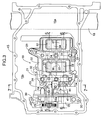
FIG. 3] FIG. 3 is a view from arrowed line 3-3 inFIG. 2 (first embodiment). - [
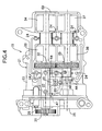
FIG. 4] FIG. 4 is a view from arrowed line 4-4 inFIG. 2 (first embodiment). - [
FIG. 5] FIG. 5 is a sectional view along line 5-5 inFIG. 3 (first embodiment). - [
FIG. 6] FIG. 6 is a sectional view along line 6-6 inFIG. 3 (first embodiment). - [
FIG. 7] FIG. 7 is a sectional view along line 7-7 inFIG. 3 (first embodiment). - [
FIG. 8] FIG. 8 is a sectional view along line 8-8 inFIG. 7 (first embodiment). - [
FIG. 9] FIG. 9 is a view, corresponding toFIG. 7 , related to a second embodiment (second embodiment). -
- 11
- Cylinder block
- 15
- Oil pan
- 15a
- Shallow bottom part
- 15b
- Deep bottom part
- 18
- Exhaust pipe (exhaust gas passage)
- 21
- Balancer housing
- 27
- Driven balancer shaft (balancer shaft)
- 28
- Follower balancer shaft (balancer shaft)
- 47
- Oil level sensor (oil sensor)
- 54
- Cover member
- 54b
- Breather hole
- 55
- Sensing element
- 56
- Shielding part
- 56a
- Air vent hole
- Modes for carrying out the present invention are explained below by reference to drawings.
-
FIG. 1 to FIG. 8 show a first embodiment of the present invention. - As is clear from
FIG. 1 , a diesel engine E transversely mounted in an engine compartment of an automobile has acylinder block 11, acylinder head 12 and head cover 13 joined to an upper part thereof, and acrankcase 14 andoil pan 15 joined to a lower part thereof. Anexhaust pipe 18 connected via a DPF (Diesel Particulate Filter) 17 to anexhaust manifold 16 joined to a front face of thecylinder head 12 extends to the rear of a vehicle body via a lower face of theoil pan 15. Asecondary balancer system 19 that reduces secondary vibration of the engine E is provided between the lower face of thecylinder block 11 and theoil pan 15. Acrankshaft 20 is rotatably supported on mating faces of thecylinder block 11 and thecrankcase 14. - The structure of the
secondary balancer system 19 is now explained by reference toFIG. 2 to FIG. 6 . - A
balancer housing 21 of thesecondary balancer system 19 is formed by joining anupper housing 22 and alower housing 23 via a plurality ofbolts 24, and further joining aside housing 25 to a right side face of thelower housing 23 via a plurality ofbolts 26, and a drivenbalancer shaft 27 and afollower balancer shaft 28 are supported therewithin in parallel to thecrankshaft 20. Thebalancer housing 21 is fixed to a lower face of thecrankcase 14 via twobolts upper housing 22 and thelower housing 23 from bottom to top and twobolts side housing 25 from bottom to top.Openings upper housing 22, anopening 63 is formed in mating faces of theupper housing 22 and thelower housing 23, and anopening 64 is formed between theupper housing 22 and theside housing 25. The interior of thebalancer housing 21 communicates with the interior of theoil pan 15 via theseopenings - Provided on the driven
balancer shaft 27 positioned on the rear side of the vehicle body are, going from one end to the other end, a drivensprocket 31, a drivengear 32, afirst balancer weight 33, and asecond balancer weight 34. Provided on thefollower balancer shaft 28 positioned on the front side of the vehicle body are, going from one end to the other end, afollower gear 35, afirst balancer weight 36, and asecond balancer weight 37. - An endless chain 39 (see
FIG. 1 andFIG. 2 ) is wrapped around a drive sprocket 38 (seeFIG. 1 ) provided on thecrankshaft 20 and the drivensprocket 31 provided on the drivenbalancer shaft 27. The drivengear 32 provided on the drivenbalancer shaft 27 meshes with thefollower gear 35 provided on thefollower balancer shaft 28. - Rotation of the
crankshaft 20 due to the engine E running is transmitted to the drivenbalancer shaft 27 via thedrive sprocket 38, theendless chain 39, and the drivensprocket 31, and rotation of the drivenbalancer shaft 27 is transmitted to thefollower balancer shaft 28 via the drivengear 32 and thefollower gear 35. Since the number of teeth of thedrive sprocket 38 of thecrankshaft 20 is set at twice the number of teeth of the drivensprocket 31 of the drivenbalancer shaft 28, and the number of teeth of the drivengear 32 is set equal to the number of teeth of thefollower gear 35, the drivenbalancer shaft 27 and thefollower balancer shaft 28 rotate in directions opposite to each other at a rotational speed twice the rotational speed of thecrankshaft 20, and secondary vibration of the engine E is suppressed by the first andsecond balancer weights balancer shaft 27 and thefollower balancer shaft 28. - A trochoidal
type oil pump 43 having aninner rotor 42 meshing with anouter rotor 41 is housed in arecess 40 formed in a mating face of thelower housing 23 via which it is joined to theside housing 25. Apump shaft 44 fixed to theinner rotor 42 is joined to thefollower balancer shaft 28 placed coaxially therewith via acoupling 45. Afilter 46 for filtering oil taken into theoil pump 43 is housed in a bottom part of thelower housing 23. - As is clear from
FIG. 2 , with regard to theoil pan 15, a bottom part on the vehicle body left-hand side (right-hand side in the figure) is a shallowbottom part 15a that is stepped shallower, and the remaining part is a deepbottom part 15b that is deeper than the shallowbottom part 15a. The shallowbottom part 15a is provided at a position where it does not interfere with thesecondary balancer system 19, and theexhaust pipe 18 is placed by utilizing a space formed beneath the shallowbottom part 15a. - As is clear from
FIG. 2 ,FIG. 7 , andFIG. 8 , anoil level sensor 47 for detecting the oil level within theoil pan 15 includes a plate-shaped mountingpart 48 and a tower-shapedsensing part 49 extending upward from the center of the mountingpart 48. Anopening 15d is formed in the center of arecess 15c formed by recessing upward the deepbottom part 15b of theoil pan 15, and with regard to theoil level sensor 47, in a state in which thesensing part 49 is inserted into theoil pan 15 via theopening 15d, the mountingpart 48 is fixed to therecess 15c around theopening 15d via aseal member 50 by means of threebolts 51. In order to protect the mountingpart 48 of theoil level sensor 47, a plate-shapedcover member 52 is fixed to therecess 15c of theoil pan 15 via a plurality ofbolts 53. - The
sensing part 49 of theoil level sensor 47 includes ahollow cover member 54; a transversely long slit-shapedoil hole 54a communicating with engine oil within theoil pan 15 is formed at the lower end of thecover member 54, and abreather hole 54b communicating with air within thebalancer housing 21 is formed at the upper end of thecover member 54. Therefore, the oil level within thecover member 54 of thesensing part 49 moves up and down so as to coincide with the oil level within the balancer housing 21 (that is, the oil level within the oil pan 15). - A plate-shaped
sensing element 55 is placed in the interior of thecover member 54 of thesensing part 49 of theoil level sensor 47. After thesensing element 55 is heated to a temperature that is higher than the oil temperature by, for example, 10°C by passing current through thesensing element 55 so as to generate heat, the time taken for the temperature to decrease by, for example, 5°C is measured. When the oil level is high, heat radiation from thesensing element 55 to the engine oil is promoted and the temperature decreases quickly, whereas when the oil level is low, heat radiation from thesensing element 55 to the engine oil is suppressed and the temperature decreases slowly, thus enabling the oil level within theoil pan 15 to be detected. - The
upper housing 22 and theside housing 25 are not in intimate contact with each other but are spaced from each other, and in that portion thebalancer housing 21 opens widely via theopening 64. Anopening 65 is formed in thelower housing 23 positioned beneath theopening 64, thesensing part 49 of theoil level sensor 47 passes through theopening 65 of thelower housing 23 from bottom to top, and projects between the drivenbalancer shaft 27 and thefollower balancer shaft 28 within thebalancer housing 21. - The shielding
part 56 projects from theupper housing 22 toward theopening 64 of thebalancer housing 21. The shieldingpart 56 is an inverted cup-shaped member having its lower face open, and the shieldingpart 56 covers an upper end part of thesensing part 49 of theoil level sensor 47. Anair vent hole 56a is formed in an upper face of the shieldingpart 56 at a position higher than thebreather hole 54b of thesensing part 49 of theoil level sensor 47. - The operation of the embodiment of the present invention having the above-mentioned arrangement is now explained.
- When the oil level varies due to agitation of engine oil within the
oil pan 15 due to shaking, acceleration/deceleration, turning, etc. of the vehicle body, the detection precision of theoil level sensor 47 deteriorates, but in the interior of thebalancer housing 21, in particular a space between the drivenbalancer shaft 27 and thefollower balancer shaft 28 supported on the interior of thebalancer housing 21, variation of the oil level is smoothed and becomes small. Therefore, placing thesensing part 49 of theoil level sensor 47 in the space between the drivenbalancer shaft 27 and thefollower balancer shaft 28 within thebalancer housing 21 enables variation of the oil level to be minimized and the detection precision to be enhanced without providing a special baffle plate. - Furthermore, forming the shallow
bottom part 15a in theoil pan 15 for placing theexhaust pipe 18 makes it difficult to ensure a space for placing theoil level sensor 47 within theoil pan 15, but this problem can be solved by placing theoil level sensor 47 by utilizing a space within thebalancer housing 21 placed in the deepbottom part 15b of theoil pan 15. - As is clear from
FIG. 3 , theexhaust pipe 18 and theoil level sensor 47 are placed so as not to overlap each other in plan view. This placement ensures that there is a distance between the hightemperature exhaust pipe 18 and theoil level sensor 47, which is susceptible to heat, thus preventing the detection precision of theoil level sensor 47 from deteriorating due to heat. - Moreover, when engine oil splashes enter into the
breather hole 54b of thecover member 54 of theoil level sensor 47, the detection precision is affected, but since thebreather hole 54b is covered by the shieldingpart 56, it is possible to prevent splashes entering from thebreather hole 54b. In this case, since the shieldingpart 56 is integrated with theupper housing 22 of thebalancer housing 21, the number of components can be reduced compared with a case in which the shieldingpart 56 is formed from an independent component. - Furthermore, when an opening part at the lower end of the shielding
part 56 is submerged under the liquid surface of engine oil, if air is sealed within the shieldingpart 56, the pressure of the internal space varies in response to variation in the oil level. As a result, the inner pressure of thecover member 54 communicating with the internal space via thebreather hole 54b also changes, the liquid level of engine oil within thecover member 54 also varies, and the detection precision of theoil level sensor 47 deteriorates. - However, in accordance with the present embodiment, since the
air vent hole 56a is formed in the upper face of the shieldingpart 56, it is possible by means of theair vent hole 56a to prevent air from being sealed in the internal space and to avoid any degradation in the detection precision of theoil level sensor 47. Furthermore, since theair vent hole 56a opens vertically and thebreather hole 54b opens horizontally, it is possible to suppress the possibility of engine oil splashing through both theair vent hole 56a and thebreather hole 54b and entering thecover member 54. - In this embodiment the
air vent hole 56a of the shieldingpart 56 is provided at a position higher than thebreather hole 54b of thesensing part 49, but as long as it is a position that does not face the opening direction of thebreather hole 54b (preferably a position displaced by 180°), the same effects can be obtained by providing theair vent hole 56a at a position lower than thebreather hole 54b. Due to this layout, the degree of freedom in the position at which theair vent hole 56a is provided increases, it becomes possible to open theair vent hole 56a horizontally, and it is possible to prevent any degradation in the detection precision of theoil level sensor 47 due to oil scattering within theoil pan 15 or oil dripping from above. - A second embodiment of the present invention is explained by reference to
FIG. 9 . - In the first embodiment, the shielding
part 56 is formed integrally with theupper housing 22, but a shieldingpart 56 of the second embodiment is formed as an independent member, and is mounted on a lower face of anopening 65 of alower housing 23 of abalancer housing 21 viabolts part 56 is a tapered tubular member tapering from a lower part to an upper part, and covers substantially the whole of asensing part 49 of anoil level sensor 47 projecting into anoil pan 15. - In this way, covering substantially the whole of the
sensing part 49 with the shieldingpart 56 enables the influence of the splashing of engine oil to be further reliably eliminated, and the detection precision of theoil level sensor 47 to be yet further enhanced. Furthermore, when theoil pan 15 is detached from thecrankcase 14 in the direction of arrow A, since the shieldingpart 56 mounted on thebalancer housing 21 has a downwardly widening shape, it is possible to prevent the upper end of theoil level sensor 47 mounted on theoil pan 15 from interfering with the inner face of the shieldingpart 56. - The arrangement and effects of the second embodiment are otherwise the same as the above-mentioned arrangement and effects of the first embodiment.
- Embodiments of the present invention are described in detail above, but the present invention may be modified in a variety of ways as long as the modifications do not depart from the spirit and scope thereof.
- For example, in the embodiment the
oil level sensor 47 for detecting the level of engine oil is explained, but the present invention may be applied to any other oil sensor for detecting the temperature or the degree of deterioration of engine oil. - Furthermore, in the second embodiment, the shielding
part 56 covers substantially the whole of thesensing part 49 of theoil level sensor 47, but an operational effect comparable to that of the case where the whole is covered can be obtained by covering at least the upper half of thesensing part 49.
Claims (9)
- An oil sensor placement structure in an engine, the engine comprising a balancer housing (21) for housing a mutually parallel pair of balancer shafts (27, 28) between a lower face of a cylinder block (11) and an oil pan (15) storing engine oil,
the structure being characterized in that an oil sensor (47) provided in a bottom part of the oil pan (15) so as to stand vertically upright is placed between the pair of balancer shafts (27, 28). - An oil sensor placement structure in an engine, the engine comprising a balancer housing (21) for housing a mutually parallel pair of balancer shafts (27, 28) between a lower face of a cylinder block (11) and an oil pan (15) storing engine oil,
the structure being characterized in that an oil sensor (47) provided in a bottom part of the oil pan (15) so as to stand vertically upright is placed so as to project into the interior of the balancer housing (21). - The oil sensor placement structure in an engine according to Claim 1 or Claim 2, wherein an exhaust gas passage (18) through which exhaust gas flows is placed beneath the oil pan (15), and the oil sensor (47) is placed at a position where the oil sensor does not overlap with the exhaust gas passage (18) when viewed vertically.
- The oil sensor placement structure in an engine according to Claim 1 or Claim 2, wherein a bottom part of the oil pan (15) comprises a shallow bottom part (15a) and a deep bottom part (15b) having different depths, the exhaust gas passage (18) through which exhaust gas flows is placed beneath the shallow bottom part (15a), and the oil sensor (47) is placed above the deep bottom part (15b).
- The oil sensor placement structure in an engine according to any one of Claim 1 to Claim 4, wherein the oil sensor (47) comprises a cover member (54) covering a sensing element (55), and a breather hole (54b) formed in the vicinity of the upper end of the cover member (54) is covered by a shielding part (56) provided on the balancer housing (21).
- The oil sensor placement structure in an engine according to Claim 5, wherein the shielding part (56) surrounds at least an upper half of a portion of the oil sensor (47) exposed within the oil pan (15).
- The oil sensor placement structure in an engine according to Claim 5 or Claim 6, wherein the shielding part (56) is formed as a separate body from the balancer housing (21) and is mounted on the balancer housing (21).
- The oil sensor placement structure in an engine according to any one of Claim 5 to Claim 7, wherein an air vent hole (56a) providing communication between the interior and exterior of the shielding part (56) is formed at a position of the shielding part (56) that is higher than the breather hole (54b).
- The oil sensor placement structure in an engine according to any one of Claim 5 to Claim 7, wherein an air vent hole (56a) providing communication between the interior and exterior of the shielding part (56) is formed at a position of the shielding part (56) that does not face the opening direction of the breather hole (54b).
Applications Claiming Priority (2)
| Application Number | Priority Date | Filing Date | Title |
|---|---|---|---|
| JP2006166518A JP4573808B2 (en) | 2006-06-15 | 2006-06-15 | Oil sensor arrangement structure in the engine |
| PCT/JP2007/057984 WO2007145017A1 (en) | 2006-06-15 | 2007-04-11 | Oil sensor placement structure of engine |
Publications (3)
| Publication Number | Publication Date |
|---|---|
| EP2028349A1 true EP2028349A1 (en) | 2009-02-25 |
| EP2028349A4 EP2028349A4 (en) | 2011-01-05 |
| EP2028349B1 EP2028349B1 (en) | 2013-12-11 |
Family
ID=38831538
Family Applications (1)
| Application Number | Title | Priority Date | Filing Date |
|---|---|---|---|
| EP07741420.9A Not-in-force EP2028349B1 (en) | 2006-06-15 | 2007-04-11 | Oil sensor placement structure of engine |
Country Status (7)
| Country | Link |
|---|---|
| US (1) | US7931004B2 (en) |
| EP (1) | EP2028349B1 (en) |
| JP (1) | JP4573808B2 (en) |
| CN (1) | CN101449031B (en) |
| CA (1) | CA2651955C (en) |
| MX (1) | MX2008015615A (en) |
| WO (1) | WO2007145017A1 (en) |
Families Citing this family (14)
| Publication number | Priority date | Publication date | Assignee | Title |
|---|---|---|---|---|
| JP4708375B2 (en) * | 2007-02-14 | 2011-06-22 | 本田技研工業株式会社 | Oil sensor |
| JP5480023B2 (en) * | 2010-06-11 | 2014-04-23 | 本田技研工業株式会社 | Internal combustion engine for saddle-ride type vehicles |
| JP5728182B2 (en) * | 2010-09-06 | 2015-06-03 | 川崎重工業株式会社 | Cylinder tilting engine |
| JP5783156B2 (en) * | 2012-10-24 | 2015-09-24 | トヨタ自動車株式会社 | Internal combustion engine |
| WO2014209897A2 (en) * | 2013-06-25 | 2014-12-31 | Cummins Filtration Ip, Inc | Fluid quality monitoring and filtration system |
| JP5831506B2 (en) * | 2013-07-11 | 2015-12-09 | トヨタ自動車株式会社 | Connector mounting structure, mounting success / failure inspection tool, mounting success / failure inspection method |
| US8904988B1 (en) * | 2013-07-16 | 2014-12-09 | GM Global Technology Operations LLC | Vertically disposed oil pan baffle |
| JP6337439B2 (en) * | 2013-10-25 | 2018-06-06 | スズキ株式会社 | Motorcycle |
| US9714859B1 (en) * | 2016-01-21 | 2017-07-25 | United Technologies Corporation | Inverted oil level sensor assembly |
| CN108223049A (en) * | 2018-02-07 | 2018-06-29 | 广西玉柴机器股份有限公司 | Engine oil pan structure |
| JP2020153319A (en) * | 2019-03-20 | 2020-09-24 | いすゞ自動車株式会社 | Engine oil amount estimation device and engine oil amount estimation method |
| KR20220096104A (en) * | 2020-12-30 | 2022-07-07 | 현대두산인프라코어(주) | Oil Level Sensor Cover and Engine having the same |
| CN115012172A (en) * | 2021-03-05 | 2022-09-06 | 松下家电(中国)有限公司 | Household appliance |
| CN115182803A (en) * | 2022-08-18 | 2022-10-14 | 中船动力镇江有限公司 | Marine diesel engine crankcase oil collection monitoring devices that splashes |
Family Cites Families (19)
| Publication number | Priority date | Publication date | Assignee | Title |
|---|---|---|---|---|
| US4245595A (en) * | 1977-09-13 | 1981-01-20 | Nissan Motor Company, Limited | Internal combustion engine for motor vehicles |
| US4256069A (en) * | 1978-02-28 | 1981-03-17 | Yamaha Hatsudori Kabushiri Kaisha | Lubricant oil level detecting device for internal combustion engines |
| CA1165835A (en) * | 1981-12-23 | 1984-04-17 | Stephen M. Stenstrom | Conductive fluid detecting method and apparatus |
| US4745895A (en) * | 1985-10-15 | 1988-05-24 | Briggs & Stratton Corp. | Liquid monitoring apparatus |
| JPS632818U (en) * | 1986-06-24 | 1988-01-09 | ||
| JPS6390611A (en) * | 1986-10-02 | 1988-04-21 | Honda Motor Co Ltd | Lubricating oil shortage detection device for internal combustion engines |
| JPH0342010U (en) * | 1989-08-30 | 1991-04-22 | ||
| JPH056115U (en) * | 1991-07-04 | 1993-01-29 | 日野自動車工業株式会社 | Oil level detection device for vehicle engine |
| JP3206114B2 (en) * | 1992-07-17 | 2001-09-04 | 日産自動車株式会社 | Engine with balancer shaft |
| US5435170A (en) * | 1993-12-30 | 1995-07-25 | Voelker; Paul J. | Method and apparatus for fluid quality sensing |
| US5687687A (en) * | 1995-06-07 | 1997-11-18 | Cummins Engine Company, Inc. | Oil level sensor system |
| JPH1130115A (en) | 1997-07-09 | 1999-02-02 | Suzuki Motor Corp | Baffle plate |
| JP3724420B2 (en) | 2001-07-03 | 2005-12-07 | 株式会社デンソー | Oil detection device |
| US20030041659A1 (en) * | 2001-09-04 | 2003-03-06 | Detroit Diesel Corporation | Electrically conductive engine oil pan sensor mounting arrangement |
| US7124731B2 (en) * | 2003-09-19 | 2006-10-24 | Honda Motor Co., Ltd. | Internal combustion engine with oil temperature sensor |
| DE102004021394B4 (en) * | 2004-04-30 | 2006-09-28 | Wacker Construction Equipment Ag | Oil level monitoring system for internal combustion engine |
| JP2006077674A (en) * | 2004-09-09 | 2006-03-23 | Ngk Spark Plug Co Ltd | Liquid state detection sensor |
| EP2385368B1 (en) * | 2005-09-09 | 2013-10-16 | Honda Motor Co., Ltd. | Oil sensor mounting structure |
| JP4512014B2 (en) * | 2005-09-09 | 2010-07-28 | 本田技研工業株式会社 | Oil pan for engine |
-
2006
- 2006-06-15 JP JP2006166518A patent/JP4573808B2/en not_active Expired - Fee Related
-
2007
- 2007-04-11 WO PCT/JP2007/057984 patent/WO2007145017A1/en not_active Ceased
- 2007-04-11 CN CN2007800179908A patent/CN101449031B/en not_active Expired - Fee Related
- 2007-04-11 US US12/314,331 patent/US7931004B2/en not_active Expired - Fee Related
- 2007-04-11 MX MX2008015615A patent/MX2008015615A/en active IP Right Grant
- 2007-04-11 CA CA2651955A patent/CA2651955C/en not_active Expired - Fee Related
- 2007-04-11 EP EP07741420.9A patent/EP2028349B1/en not_active Not-in-force
Non-Patent Citations (2)
| Title |
|---|
| No further relevant documents disclosed * |
| See also references of WO2007145017A1 * |
Also Published As
| Publication number | Publication date |
|---|---|
| US7931004B2 (en) | 2011-04-26 |
| CA2651955A1 (en) | 2007-12-21 |
| US20100059011A1 (en) | 2010-03-11 |
| CN101449031A (en) | 2009-06-03 |
| MX2008015615A (en) | 2009-01-09 |
| JP2007332883A (en) | 2007-12-27 |
| JP4573808B2 (en) | 2010-11-04 |
| CN101449031B (en) | 2011-07-13 |
| WO2007145017A1 (en) | 2007-12-21 |
| EP2028349A4 (en) | 2011-01-05 |
| EP2028349B1 (en) | 2013-12-11 |
| CA2651955C (en) | 2010-12-07 |
Similar Documents
| Publication | Publication Date | Title |
|---|---|---|
| EP2028349B1 (en) | Oil sensor placement structure of engine | |
| US7047927B2 (en) | Engine balancer system | |
| JP3468327B2 (en) | 4-cycle outboard | |
| JP2008223596A (en) | Internal combustion engine and vehicle equipped with the same | |
| JP2008223880A (en) | Internal combustion engine and vehicle equipped with the same | |
| US8534257B2 (en) | Engine case | |
| EP1762847B1 (en) | Oil pan for automotive engines | |
| EP2154340B1 (en) | Internal Combustion Engine | |
| JP4021068B2 (en) | V-type internal combustion engine for motorcycles | |
| EP1233153A1 (en) | Engine lubrication system | |
| JP6117990B2 (en) | Engine lubrication structure | |
| JP4322079B2 (en) | Internal combustion engine with oil temperature sensor | |
| JPH0571585A (en) | Balancer for engine unit for scooter | |
| JP6061752B2 (en) | Internal combustion engine | |
| US6935298B2 (en) | Lubricating device for motorcycle engine | |
| JP2002242642A (en) | Outboard motor with 4-stroke engine | |
| JP3993328B2 (en) | Lubricating device for internal combustion engine | |
| JP2007321746A (en) | Vertical internal combustion engine having a belt-type transmission mechanism | |
| JP2025033498A (en) | Oil Level Detection Device | |
| JPWO2016075918A1 (en) | Mechanical device having a plurality of rotating shafts | |
| JP2015124696A (en) | Internal combustion engine | |
| JP2009228560A (en) | Crank angle sensor mounting structure in internal combustion engine | |
| JPH08158846A (en) | Internal combustion engine oil pan structure | |
| JP2000265819A (en) | Breather structure for engine | |
| JP2004218488A (en) | Engine unit for vehicle |
Legal Events
| Date | Code | Title | Description |
|---|---|---|---|
| PUAI | Public reference made under article 153(3) epc to a published international application that has entered the european phase |
Free format text: ORIGINAL CODE: 0009012 |
|
| 17P | Request for examination filed |
Effective date: 20081107 |
|
| AK | Designated contracting states |
Kind code of ref document: A1 Designated state(s): AT BE BG CH CY CZ DE DK EE ES FI FR GB GR HU IE IS IT LI LT LU LV MC MT NL PL PT RO SE SI SK TR |
|
| AX | Request for extension of the european patent |
Extension state: AL BA HR MK RS |
|
| DAX | Request for extension of the european patent (deleted) | ||
| RBV | Designated contracting states (corrected) |
Designated state(s): DE ES FR GB IT |
|
| A4 | Supplementary search report drawn up and despatched |
Effective date: 20101208 |
|
| 17Q | First examination report despatched |
Effective date: 20110113 |
|
| GRAP | Despatch of communication of intention to grant a patent |
Free format text: ORIGINAL CODE: EPIDOSNIGR1 |
|
| INTG | Intention to grant announced |
Effective date: 20130703 |
|
| GRAS | Grant fee paid |
Free format text: ORIGINAL CODE: EPIDOSNIGR3 |
|
| GRAA | (expected) grant |
Free format text: ORIGINAL CODE: 0009210 |
|
| RIN1 | Information on inventor provided before grant (corrected) |
Inventor name: ENDO, YUSUKE Inventor name: KOYAMA, YOSHIAKI Inventor name: UESHIMA, HIDEO |
|
| AK | Designated contracting states |
Kind code of ref document: B1 Designated state(s): DE ES FR GB IT |
|
| REG | Reference to a national code |
Ref country code: GB Ref legal event code: FG4D |
|
| REG | Reference to a national code |
Ref country code: DE Ref legal event code: R096 Ref document number: 602007034206 Country of ref document: DE Effective date: 20140206 |
|
| PG25 | Lapsed in a contracting state [announced via postgrant information from national office to epo] |
Ref country code: ES Free format text: LAPSE BECAUSE OF FAILURE TO SUBMIT A TRANSLATION OF THE DESCRIPTION OR TO PAY THE FEE WITHIN THE PRESCRIBED TIME-LIMIT Effective date: 20131211 |
|
| REG | Reference to a national code |
Ref country code: DE Ref legal event code: R097 Ref document number: 602007034206 Country of ref document: DE |
|
| PLBE | No opposition filed within time limit |
Free format text: ORIGINAL CODE: 0009261 |
|
| STAA | Information on the status of an ep patent application or granted ep patent |
Free format text: STATUS: NO OPPOSITION FILED WITHIN TIME LIMIT |
|
| 26N | No opposition filed |
Effective date: 20140912 |
|
| GBPC | Gb: european patent ceased through non-payment of renewal fee |
Effective date: 20140411 |
|
| REG | Reference to a national code |
Ref country code: DE Ref legal event code: R097 Ref document number: 602007034206 Country of ref document: DE Effective date: 20140912 |
|
| REG | Reference to a national code |
Ref country code: FR Ref legal event code: ST Effective date: 20141231 |
|
| PG25 | Lapsed in a contracting state [announced via postgrant information from national office to epo] |
Ref country code: GB Free format text: LAPSE BECAUSE OF NON-PAYMENT OF DUE FEES Effective date: 20140411 |
|
| REG | Reference to a national code |
Ref country code: DE Ref legal event code: R084 Ref document number: 602007034206 Country of ref document: DE |
|
| PG25 | Lapsed in a contracting state [announced via postgrant information from national office to epo] |
Ref country code: FR Free format text: LAPSE BECAUSE OF NON-PAYMENT OF DUE FEES Effective date: 20140430 |
|
| REG | Reference to a national code |
Ref country code: DE Ref legal event code: R084 Ref document number: 602007034206 Country of ref document: DE Effective date: 20150210 |
|
| PG25 | Lapsed in a contracting state [announced via postgrant information from national office to epo] |
Ref country code: IT Free format text: LAPSE BECAUSE OF FAILURE TO SUBMIT A TRANSLATION OF THE DESCRIPTION OR TO PAY THE FEE WITHIN THE PRESCRIBED TIME-LIMIT Effective date: 20131211 |
|
| PGFP | Annual fee paid to national office [announced via postgrant information from national office to epo] |
Ref country code: DE Payment date: 20220302 Year of fee payment: 16 |
|
| REG | Reference to a national code |
Ref country code: DE Ref legal event code: R119 Ref document number: 602007034206 Country of ref document: DE |
|
| PG25 | Lapsed in a contracting state [announced via postgrant information from national office to epo] |
Ref country code: DE Free format text: LAPSE BECAUSE OF NON-PAYMENT OF DUE FEES Effective date: 20231103 |