EP2028242A1 - Inkjet ink, and ink cartridge, inkjet recording method, inkjet recording apparatus and ink record using the same - Google Patents
Inkjet ink, and ink cartridge, inkjet recording method, inkjet recording apparatus and ink record using the same Download PDFInfo
- Publication number
- EP2028242A1 EP2028242A1 EP08252661A EP08252661A EP2028242A1 EP 2028242 A1 EP2028242 A1 EP 2028242A1 EP 08252661 A EP08252661 A EP 08252661A EP 08252661 A EP08252661 A EP 08252661A EP 2028242 A1 EP2028242 A1 EP 2028242A1
- Authority
- EP
- European Patent Office
- Prior art keywords
- ink
- inkjet
- repellent layer
- fluorine
- pigment
- Prior art date
- Legal status (The legal status is an assumption and is not a legal conclusion. Google has not performed a legal analysis and makes no representation as to the accuracy of the status listed.)
- Granted
Links
- 0 IIC(CCC1)(CC(CCC2)C1CC2(*I)C1CCCC1)C1CCCCC1 Chemical compound IIC(CCC1)(CC(CCC2)C1CC2(*I)C1CCCC1)C1CCCCC1 0.000 description 2
Images




Classifications
-
- C—CHEMISTRY; METALLURGY
- C09—DYES; PAINTS; POLISHES; NATURAL RESINS; ADHESIVES; COMPOSITIONS NOT OTHERWISE PROVIDED FOR; APPLICATIONS OF MATERIALS NOT OTHERWISE PROVIDED FOR
- C09D—COATING COMPOSITIONS, e.g. PAINTS, VARNISHES OR LACQUERS; FILLING PASTES; CHEMICAL PAINT OR INK REMOVERS; INKS; CORRECTING FLUIDS; WOODSTAINS; PASTES OR SOLIDS FOR COLOURING OR PRINTING; USE OF MATERIALS THEREFOR
- C09D11/00—Inks
- C09D11/02—Printing inks
- C09D11/10—Printing inks based on artificial resins
- C09D11/101—Inks specially adapted for printing processes involving curing by wave energy or particle radiation, e.g. with UV-curing following the printing
Definitions
- the present invention relates to an inkjet ink suitably used for image recording by an inkjet method, and an ink cartridge, inkjet recording method, inkjet recording apparatus and ink record using the inkjet ink.
- Inkjet recording has advantages over other recording methods in that it facilitates full-colorization because of the process that is simpler than those of other recording methods and in that high-resolution images can be obtained even with a simply configured apparatus.
- JP-A Japanese Patent Application Laid-Open
- JP-A No. 2003-226827 discloses an ink containing polymer fine particles, a water insoluble or poorly-water soluble colorant, a water-soluble organic solvent and a fluorine surfactant.
- such an ink having a lower surface tension and containing a fluorine surfactant has a problem in that a nozzle plate is easily wet and discharge stability is hard to be ensured.
- JP-A No. 2004-10733 discloses an ink containing a water soluble solvent, a colorant, water and a polymer which contains at least an alkylene oxide moiety, aromatic ring moiety and carboxyl moiety in one molecule.
- JP-A No. 2004-10733 also discloses "liquid repellent treatment around a discharge port" and "an ink containing a silicone surfactant, a fluorine surfactant and the like".
- JP-A No. 2004-10733 does not disclose kinds of silicone surfactants, and the ink having a lower surface tension and containing a fluorine surfactant proposed in JP-A No. 2004-10733 is hard to ensure ink repellency.
- JP-A 2007-154021 discloses aqueous dispersions for inkjet recording, which contains a self-dispersible pigment, polymer particles and a compound containing polysiloxane skeleton, and an aqueous ink containing the aqueous dispersions.
- the ink has a surface tension of 25 mN/m to 50 mN/m, which is not intended to obtain an ink having a lower surface tension, and a nozzle plate is not particularly treated.
- the inventors of the present invention proposed adding a silicone resin in an ink repellent layer of a nozzle plate in an inkjet nozzle so as to decrease a surface tension of an inkjet ink and increase wettability to a recording medium, thereby increasing color development property ( JP-A No. 2005-138383 ).
- JP-A No. 2005-138383 the color developing property of ink can be improved, but ink is needed to be excellent not only in initial ink repellency but also in mechanical durability such as resistant to wiping because of speed-up and increase of frequency of usage of printers.
- initial ink repellency can be ensured, but a dried ink fixes to an ink repellent layer upon continuous printing, causing poor ink repellency.
- JP-A No. 2008-95089 discloses an ink containing water, a water soluble organic solvent, a water dispersible resin, a pigment and any one of a fluorine surfactant and silicone surfactant as a surfactant, but fails to mention ink fixation to an ink repellent layer. Practically, the problem of the ink fixation to the ink repellent layer is not solved by the proposed formulation.
- An object of the present invention is to provide an inkjet ink capable of being prevented from fixation to an ink repellent layer and is excellent in discharge stability, and an ink cartridge, inkjet recording method, inkjet recording apparatus, and ink record using the inkjet ink.
- the present invention is based on the aforementioned finding made by the inventors, and means for solving the above-described problems are described below.
- An inkjet ink of the present invention contains at least a colorant, water, a water insoluble resin, a fluorine surfactant and a polyether-modified silicone oil, wherein the polyether-modified silicone oil has a hydrophobic value of 0.40 to 1.5 as measured using a 1 H-NMR spectrum of the polyether-modified silicone oil using tetramethylsilane (TMS) as a reference substance, and the hydrophobic value is expressed by the above Equation 1.
- the ink containing the fluorine surfactant has excellent releasability to the ink repellent layer, in which lipophilic groups are attached to the surface thereof.
- the ink fixation to the ink repellent layer containing a silicone resin is caused due to drying of the colorant and water insoluble resin in the ink.
- hydrophilic-lipophilic balance of the polyether-modified silicone oil which is added to the ink is focused on and studied, and it is found that, particularly, a hydrophobic value correlates with ink fixation to an ink repellent layer, and that the ink fixation to the ink repellent layer can be prevented by adjusting the hydrophobic value of the polyether-modified silicone oil to 0.40 to 1.5.
- hydrophilic-lipophilic balance is discussed in terms of an HLB value, however, the ink fixation to an ink repellent layer is not correlated with an HLB value, and cannot be explained only in terms of an HLB value (see Table 6).
- the hydrophobic value is 0.40 to 1.5
- the proportion of hydrophobic sites in the silicone oil is increased, allowing the silicone oil to be easily adsorbed on a water insoluble resin.
- hydrophilization of the surface of the water insoluble resin prevents the ink from fixation to an ink repellent layer, thereby improving discharge stability.
- the hydrophobic value is less than 0.40
- the silicone oil is not sufficiently adsorbed on a water insoluble resin, thereby causing ink fixation to the ink repellent layer.
- the hydrophobic value is more than 1.5
- the proportion of hydrophilic sites is relatively decreased, thus a surface of the water insoluble resin is not sufficiently hydrophilized, and does not exhibit the effect of preventing the ink from fixation.
- An inkjet recording apparatus of the present invention contains at least an inkjetting unit configured to jet the inkjet ink of the present invention so as to record an image on a recording medium by applying stimulus (energy) to the inkjet ink, and the stimulus is at least one selected from heat, pressure, vibration and light.
- the inkjetting unit applies energy to the inkjet ink of the present invention so as to jet the inkjet ink for recording an image, thereby obtaining discharge stability and high quality images.
- An inkjet recording method of the present invention is an inkjet recording method including jetting an inkjet ink from an inkjetting unit so as to record an image on a recording medium by applying a stimulus to the inkjet ink according to any one of ⁇ 1> to ⁇ 11>, wherein inkjetting unit contains a recording head whose surface provided with an opening for ink discharge has an ink repellent layer, thereby obtaining discharge stability and high quality images.
- the ink cartridge used in the present invention contains a container which contains the inkjet ink of the present invention.
- the ink cartridge is suitably used for a printer and the like using the inkjet recording method. Recording is performed using the inkjet ink contained in the ink cartridge, thereby obtaining discharge stability and high quality images.
- the ink record according to the present invention contains an image recorded on a recording medium by using the inkjet ink of the present invention.
- the ink record according to the present invention can maintain high quality images having excellent color tone on various recording media.
- the inkjet ink of the present invention contains at least a colorant, water, water insoluble resin, fluorine surfactant and polyether-modified silicone oil, and contains a water-soluble organic solvent and penetrating agent, and further contains other components as necessary.
- the inkjet ink is used for an inkjet recording apparatus containing at least an inkjet head having an ink repellent layer as described later, and can be prevented from fixation to a nozzle plate having the ink repellent layer, and has a property excellent discharge stability.
- a polyether-modified silicone oil which is contained in the inkjet ink, has a hydrophobic value of 0.40 to 1.5.
- TMS tetramethylsilane
- the integration value of a peak area from 3.5 ppm to 4.0 ppm corresponds to the number of hydrogen atoms of a hydrophilic site such as polyoxyethylene, polyoxypropylene or the like in the polyether-modified silicone oil
- the integration value of a peak area from 0 ppm to 0.3 ppm corresponds to the number of hydrogen atoms of an alkyl group (hydrophobic site) bonded to Si element in the polyether-modified silicone oil.
- the hydrophobic value which is the ratio of the integration value of a peak area from 0 ppm to 0.3 ppm to the integration value of a peak area from 3.5 ppm to 4.0 ppm
- the proportion of the hydrophobic sites in the silicone oil is increased.
- the silicone oil tends to be absorbed in the water insoluble resin, and thus the surface of the water insoluble resin is hydrophilized so as to be prevented from fixation to the ink repellent layer which has a hydrophobic surface.
- the integration value does not include the integration values of peak areas in the spectra of tetramethylsilane (TMS) as a reference substance and spinning sideband of TMS.
- the hydrophobic value expressed by Equation 1 is preferably 0.40 to 1.5, and more preferably 0.40 to 1.2.
- the hydrophobic value is less than 0.40, the silicone oil is not sufficiently adsorbed on a water insoluble resin, thereby causing ink fixation.
- the hydrophobic value is more than 1.5, the proportion of hydrophilic sites is relatively decreased, thus a surface of the water insoluble resin is not sufficiently hydrophilized, and does not exhibit the effect of preventing the ink from fixation.
- solvents such as DMSO, DMF-d7, THF-d8, acetone-d6, methanol-d4, heavy water and hexane-d14 may be used in this order.
- the solvent which firstly dissolves the sample is used.
- the hydrophobic value is indicated by rounding off a measured value to two decimal places.
- Such a polyether-modified silicone oil has a polyoxyalkylene group, which is an adduct of ethylene oxide and propylene oxide, at a side chain of dimethyl polysiloxane, and commercially available one can be used.
- examples of the commercially available polyether-modified silicone oils include DOW CORNING TORAY L-7604 (by Dow Corning Toray Co., Ltd.), and KF-353 (by Shin-Etsu Chemical Co., Ltd.).
- the amount of the polyether-modified silicone oil in the inkjet ink is preferably 0.05% by mass to 3% by mass, and more preferably 0.1% by mass to 2% by mass.
- the pigment is not particularly limited and may be appropriately selected according to the purpose.
- either an inorganic pigment or organic pigment may be used.
- organic pigments examples include azo pigments, phthalocyanine pigments, anthraquinone pigments, dioxazine pigments, indigo pigments, thioindigo pigments, perylene pigments, isoindolinone pigments, aniline black pigments, azomethine pigments and rhodamine B lake pigments.
- inorganic pigments examples include carbon blacks, iron oxides, titanium oxides, calcium carbonate, barium sulfate, aluminum hydroxide, barium yellow, iron blue, cadmium red, chrome yellow and metal particles.
- the color of the pigment is not particularly limited and may be appropriately selected according to the purpose.
- black pigments and color pigments can be used. These pigments may be used alone or in combination.
- black pigments examples include carbon blacks (C. I. Pigment Black 7) such as furnace black, lamp black, acetylene black, and channel black, metals such as copper oxides, iron oxides, (C. I. Pigment Black 11), and titanium oxides, and organic pigments such as aniline black (C. I. Pigment Black 1).
- color pigments specifically, for yellow ink include C. I. Pigment Yellow 1 (Fast Yellow G), 2, 3, 12 (Disazo Yellow AAA), 13, 14, 16, 17, 20, 23, 24, 34, 35, 37, 42 (yellow iron oxide), 53, 55, 73, 74, 75, 81, 83 (Disazo Yellow HR), 86, 93, 95, 97, 98, 100, 101, 104, 108, 109, 110, 114, 117, 120, 125, 128, 129, 137, 138, 139, 147, 148, 150, 151, 153, 154, 155, 166, 168, 180, 185.
- C. I. Pigment Yellow 1 Fluor Yellow G
- 2, 3, 12 Disazo Yellow AAA
- 13, 14, 16, 17, 20, 23, 24, 34, 35, 37, 42 yellow iron oxide
- 53, 55, 73, 74, 75, 81, 83 (Disazo Yellow HR)
- pigments for magenta ink include C. I. Pigment Red 1, 2, 3, 5, 7, 9, 12, 17, 22 (Brilliant Fast Scarlet), 23, 31, 38, 48:1 (Permanent Red 2B (Ba)), 48:2 (Permanent Red 2B (Ca)), 48:3 (Permanent Red 2B (Sr)), 48:4 (Permanent Red 2B (Mn)), 49:1, 52:2, 53:1, 57:1 (Brilliant Carmine 6B), 60:1, 63:1, 63:2, 64:1, 81 (Rhodamine 6G Lake), 83, 88, 92, 97, 101 (iron oxide red), 104, 105, 106, 108 (cadmium red), 112, 114, 122 (dimethylquinacridone), 123, 146, 149, 166, 168, 170, 172, 175, 176, 178, 179, 180, 184, 185, 190, 192, 193, 202, 209, 21
- pigments for cyan ink include C. I. Pigment Blue 1, 2, 3, 15 (Copper Phthalocyanine Blue R), 15:1, 15:2, 15:3 (Phthalocyanine Blue G), 15:4, 15:6 (Phthalocyanine Blue E), 16, 17:1, 22, 56, 60, 63, 64, Vat Blue 4, and Vat Blue 60.
- pigments for intermediate colors include C. I. Pigment Red 177, 194, 224, C. I. Pigment Orange 16, 36, 43, 51, 55, 59, 61, 71, C. I. Pigment Violet 3, 19, 23, 29, 30, 37, 40, 50 and C. I. Pigment Green 7, 36.
- a carbon black is preferably used as a black pigment.
- a preferred carbon black is produced by a furnace method and a channel method, and has a primary particle diameter of 15 nm to 40 nm, a specific surface area determined by a BET method of 50 m 2 /g to 300 m 2 /g, a DBP oil adsorption quantity of 4mL/100g to 150mL/100g, a volatile fraction of 0.5% to 10%, and a pH value of 2 to 9.
- An acidic carbon black having pH of 6 or less is particularly preferable because of high concentration.
- the average particle diameter of the pigment is not particularly limited and may be appropriately selected according to the purpose. It is preferably 10 nm to 150 nm, more preferably 20 nm to 100 nm, and still more preferably 30 nm to 80 nm. When the average particle diameter is more than 150 nm, the color saturation of a printed image may be decreased, and additionally, thickening and aggregation during ink storage and nozzle clogging during printing may easily occur. On the other hand, when the average particle diameter of the pigment is less than 10 nm, light resistance is decreased and storage stability tends to be poor.
- the average particle diameter of the pigment means an average particle diameter (D50) measured on a sample which is diluted with pure water to a pigment concentration (mass concentration) of 0.01% by mass, using MICROTRAC UPA-150 (manufactured by NIKKISO CO., LTD.) at 23°C under the conditions of a particle refractive index of 1.51, a particle density of 1.4g/cm 3 and a pure water parameter as a solvent parameter.
- the pigment is dispersed with a nonionic surfactant so as to decrease the particle diameter and particle distribution width of the pigment, and the amount of coarse particles of the pigment in the ink fixing to a nozzle plate is decreased so as to decrease damages to the ink repellent layer caused by friction of coarse particles in the ink during wiping, and thus the ink less fixes to the nozzle plate.
- the nonionic surfactant is not particularly limited and may be appropriately selected according to the kinds of pigments.
- examples thereof include polyoxyethylene alkylether such as polyoxyethylene lauryl ether, polyoxyethylene myristyl ether, polyoxyethylene cetyl ether, polyoxyethylene stearyl ether, polyoxyethylene oleyl ether; polyoxyethylene alkylphenyl ether such as polyoxyethylene octylphenyl ether, polyoxyethylene nonylphenyl ether; polyoxyethylene ⁇ -naphthylether, polyoxyethylene ⁇ -naphthylether, polyoxyethylene monostyryl phenyl ether, polyoxyethylene distyryl phenyl ether, polyoxyethylene alkyl naphthyl ether, polyoxyethylene monostyryl naphthyl ether, polyoxyethylene distyryl naphthyl ether, and a polyoxyethylene-polyoxypropylene block copolymer.
- examples thereof further include surfactants in which a part of polyoxyethylene of the nonionic surfactant listed above is substituted with polyoxypropylene, and compounds prepared by condensing aromatic ring-containing compounds with formalin such as polyoxyethylene alkyl phenyl ether.
- Hydrophilic lipophilic balance (HLB) of the nonionic surfactant is preferably 12 to 19.5, and more preferably 13 to 19.
- HLB Hydrophilic lipophilic balance
- a compound expressed by General Formula (1) is particularly preferably used. By dispersing a pigment with this compound, the average particle diameter of the pigment becomes smaller and the particle distribution can be narrowed.
- R 1 represents an alkyl group having 1 to 20 carbon atoms, an allyl group or an aralkyl group, "1" is an integer of 0 to 7, and "n” is an integer of 20 to 200.
- examples of alkyl groups having 1 to 20 carbon atoms include methyl, ethyl, n-propyl, i-propyl, butyl (n-butyl, i-butyl, t-butyl, sec-butyl); pentyl (n-pentyl, i-pentyl, neopentyl, cyclopentyl, etc.); hexyl (n-hexyl, i-hexyl, cyclohexyl, etc.); heptyl (n-heptyl, i-heptyl, etc.); octyl (n-octyl, i-octyl, t-octyl, etc.); nonyl (n-nonyl, i-nonyl, etc.); decyl (n-decyl, i-decyl, etc.); undecyl (n-decyl
- aralkyl groups examples include benzyl, phenethyl, 2-methylbenzyl, 3-methylbenzyl, and 4-methylbenzyl.
- n is preferably an integer of 20 to 200, and more preferably an integer of 25 to 60.
- n is an integer of less than 20, the dispersion stability is decreased, and the pigment may have a larger average particle diameter, and thus the color saturation tends to be poor.
- n is an integer of more than 200, an ink may have high viscosity, and it tends to be difficult to carry out printing by an inkjet method.
- the hydrophilic group of the nonionic surfactant is preferably a polyoxyethylene group.
- the hydrophilic group is preferably a polyoxyethylene group in that it can properly keep charge held on pigment particle surfaces and can reduce foamability of the ink.
- an anionic surfactant is also preferably used.
- anionic surfactants include a polyoxyethylene alkylether sulfate, polyoxyethylene alkylphenylether sulfate, polyoxyethylene monostyryl phenyl ether sulfate, polyoxyethylene distyryl phenyl ether sulfate, polyoxyethylene alkyl ether phosphate, polyoxyethylene alkylphenylether phosphate, polyoxyethylene monostyryl phenyl ether phosphate, polyoxyethylene distyryl phenyl ether phosphate, polyoxyethylene alkyl ether carboxylate, polyoxyethylene alkylphenylether carboxylate, polyoxyethylene monostyrylphenyl ether carboxylate, polyoxyethylene distyryl phenyl ether carboxylate, naphthalenesulfonate-formalin condensates, melaminesulfonate-formalin condensates, dialkyl sulfosuccinate, alkyl distyryl
- the pigment dispersion can be prepared by mixing water, a pigment and an anionic surfactant or nonionic surfactant as a dispersant, and dispersing them with a sand mill, a homogenizer, a ball mill, a paint shaker, an ultrasonic dispersing machine or the like.
- a self-dispersible pigment means a pigment in which at least one hydrophilic group is bonded directly or via another atomic group to the pigment surface, and which can be dispersed with stability, without using a dispersant.
- a hydrophilic group having ionicity is preferably used and anionic and cationic ones are particularly preferred.
- anionic hydrophilic groups include -COOM, -SO 3 M, -PO 3 HM, -PO 3 M 2 , -SO 2 NH 2 , -SO 2 NHCOR (where M represents a hydrogen atom, an alkali metal, ammonium, or an organic ammonium; R represents an alkyl group having 1 to 12 carbon atoms, an optionally substituted phenyl group or optionally substituted naphthyl group).
- colorants in which -COOM and -SO 3 M are bonded to a pigment surface are preferably used.
- methods for obtaining anionically charged pigments include a method for oxidizing a pigment with sodium hypochlorite, a sulfonation method, and a method of causing a reaction with a diazonium salt.
- Examples of the alkali metal represented by "M" in the hydrophilic group include lithium, sodium, and potassium.
- Examples of the organic ammoniums include mono- to tri-methylammonium, mono- to tri-ethylammonium, and mono-to tri-methanolammonium.
- Examples of methods for obtaining anionically charged pigments include methods by which -COONa is introduced to the pigment surface, such as a method for oxidizing a pigment with sodium hypochlorite, a sulfonation method, and a method of causing a reaction with a diazonium salt.
- Quaternary ammonium groups are preferred as the aforementioned cationic hydrophilic groups bonded to a pigment surface.
- a pigment in which at least one of the below-described quaternary ammonium groups is bonded to the pigment surface is more preferably used.
- the hydrophilic group may be bonded to the pigment surface via another atomic group.
- other atomic groups include an alkyl group having 1 to 12 carbon atoms, an optionally substituted phenyl group or optionally substituted naphthyl group.
- Specific examples representing the case in which the aforementioned hydrophilic group is bonded to the pigment surface via another atomic group include -C 2 H 4 COOM (where M represents an alkyl metal or quaternary ammonium), -PhSO 3 M (where Ph represents a phenyl group and M represents an alkali metal or quaternary ammonium), and -C 5 H 10 NH 3 + .
- the pigment base before introducing the hydrophilic group, is not particularly limited and may be appropriately selected from the same as those described in the (1) pigment dispersion according to the purpose.
- a self-dispersible carbon black is particularly preferred.
- dyes When a dye is used as a colorant, an ink excellent in color tone can be obtained.
- dyes include water-soluble dyes, oil-soluble dyes, and dispersible dyes.
- Water-soluble dyes are classified based on the color index thereof into acidic dyes, direct dyes, basic dyes, reactive dyes and food dyes, and it is preferred that dyes having high resistance to water and light be used.
- acidic dyes and food dyes examples include C. I. Acid Yellow 17, 23, 42, 44, 79, 142; C.I. Acid Red 1, 8, 13, 14, 18, 26, 27, 35, 37, 42, 52, 82, 87, 89, 92, 97, 106, 111, 114, 115, 134, 186, 249, 254, 289; C. I. Acid Blue 9, 29, 45, 92, 249; C. I. Acid Black 1, 2, 7, 24, 26, 94; C. I. Food Yellow 3,4; C. I. Food Red 7, 9, 14; and C. I. Food Black 1, 2.
- Examples of direct dyes include C. I. Direct Yellow 1, 12, 24, 26, 33, 44, 50, 86, 120, 132, 142, 144; C. I. Direct Red 1, 4, 9, 13, 17, 20, 28, 31, 39, 80, 81, 83, 89, 225, 227; C. I. Direct Orange 26, 29, 62, 102; C. I. Direct Blue 1, 2, 6, 15, 22, 25, 71, 76, 79, 86, 87, 90, 98, 163, 165, 199, 202; and C. I. Direct Black 19, 22, 32, 38, 51, 56, 71, 74, 75, 77, 154, 168, 171.
- Examples of basic dyes include C. I. Basic Yellow 1, 2, 11, 13, 14, 15, 19, 21, 23, 24, 25, 28, 29, 32, 36, 40, 41, 45, 49, 51, 53, 63, 64, 65, 67, 70, 73, 77, 87, 91; C. I. Basic Red 2, 12, 13, 14, 15, 18, 22, 23, 24, 27, 29, 35, 36, 38, 39, 46, 49, 51, 52, 54, 59, 68, 69, 70, 73, 78, 82, 102, 104, 109, 112; C. I.
- Basic Blue 1 3, 5, 7, 9, 21, 22, 26, 35, 41, 45, 47, 54, 62, 65, 66, 67, 69, 75, 77, 78, 89, 92, 93, 105, 117, 120, 122, 124, 129, 137, 141, 147, 155; and C.
- Basic Black 2 8.
- reactive dyes examples include C. I. Reactive Black 3, 4, 7, 11, 12, 17; C. I. Reactive Yellow 1, 5, 11, 13, 14, 20, 21, 22, 25, 40, 47, 51, 55, 65, 67; C. I. Reactive Red 1, 14, 17, 25, 26, 32, 37, 44, 46, 55, 60, 66, 74, 79, 96, 97; and C. I. Reactive Blue 1, 2, 7, 14, 15, 23, 32, 35, 38, 41, 63, 80, 95.
- the amount of the colorant in the inkjet ink is preferably 1% by mass to 15% by mass, more preferably 2% by mass to 12% by mass, and still more preferably 3% by mass to 10% by mass.
- the amount of the colorant is less than 1% by mass, coloring power is not sufficient, and an image tends to be inferior in brightness.
- the amount of the colorant is more than 15% by mass, the storage stability of ink is decreased and a dull image is obtained.
- a fluorine surfactant is not particularly limited and may be appropriately selected according to the purpose, and suitably synthesized one or a commercially available product may be used.
- Examples thereof include S-144 and S-145 (manufactured by Asahi Glass Co.); FC-170C, FC-430, and FRORARD FC4430 (manufactured by Sumitomo 3M Ltd.); FSO, FSO-100, FSN, FSN-100, and FS-300 (manufactured by DuPont); FT-250 and FT-251 (manufactured by Neos Co.); and PF-151N, PF-136A, PF-156A (manufactured by OMNOVA Solutions Inc.) Of these, FSO, FSO-100, FSN, FSN-100, and FS-300 (manufactured by DuPont) are preferable in that they provide excellent printing quality and storage stability. These nonionic fluorine surfactants may be used alone or in combination.
- the amount of the fluorine surfactant added in the ink is preferably 0.1 % by mass to 10% by mass, and more preferably 0.1% by mass to 5% by mass.
- the amount of the fluorine surfactant is less than 0.1% by mass, a remarkable effect of enhancement in permeability cannot be obtained.
- the amount is more than 10% by mass, the viscosity of the ink is increased to cause aggregation of the ink upon storing under a high-temperature condition, adversely affecting the reliability of the ink.
- a resin emulsion is preferably used in terms of the discharge stability of an ink, image quality and durability of a print.
- the resin emulsion has a property of thickening and aggregating when landing to a recording medium such as paper, and has effects of inhibiting permeation of a coloring component and of facilitating the fixation on paper.
- Some kinds of the resin emulsion have an effect of enhancement in abrasion resistance of a print by forming a film on paper.
- the resin emulsion is added to an ink so as to improve dispersion stability of a pigment.
- the durability of the ink repellent layer decreases because the ink easily fixes to the ink repellent layer.
- a resin emulsion is not particularly limited and may be appropriately selected according to the purpose. Examples thereof include styrene-acrylic resins, acrylic silicone resins, urethane resins and fluorine resins. Of these, urethane resins are particularly preferable.
- the emulsion resin When the emulsion resin is used as a raw material for producing a pigment ink or after an ink is produced using the emulsion resin, the emulsion resin should exist as an O/W emulsion.
- Polyurethane resin emulsions are classified into two types i.e. the one that is emulsified by using an emulsifier with a commonly used polyurethane resin which is relatively hydrophilic, and a self-emulsifiable emulsion in which a functional group capable of serving as an emulsifier is introduced to a resin itself by copolymerization. Both types of polyurethane resin emulsions can be used, however, the attention needs to be paid on a slight difference in dispersion stability between pigment and emulsion particles depending on the combination of pigment ink compositions.
- the one that is constantly excellent in dispersion stability is an anionic self-emulsifiable polyurethane emulsion resin.
- an ether polyurethane resin is more preferred than a polyester polyurethane resin or polycarbonate polyurethane resin in terms of fixation property and dispersion stability of a pigment. The reason is not clearly known, however, many non-ether polyurethane resins have weak solvent resistance and are likely to aggregate when stored under high-temperature conditions.
- the resin emulsion a commercially available product can be used.
- the commercially available resin emulsions include J-450, J-734, J-7600, J-352, J-390, J-7100, J-741, J74J, J-511, J-840, J-775, HRC-1645, and HPD-71 (styrene-acrylic resin emulsions, manufactured by Johnson Polymer Inc.); UVA383MA (acryl-silicone resin emulsion, manufactured by BASF Corporation); AP4710 (acryl-silicone resin emulsion, manufactured by SHOWA HIGHPOLYMER CO., LTD.); SF460, SF460S, SF420, SF110, SF300, and SF361 (polyurethane resin emulsions, manufactured by Nippon Unicar Company Limited); and FE4300, FE4500, and FE4400 (fluorine resin emulsions, manufactured by ASAHI GLASS CO., LTD.).
- the amount of the resin emulsion in the inkjet ink, in resin solid content is preferably 0.1% by mass to 20% by mass, and more preferably 0.2% by mass to 10% by mass.
- the content of the resin emulsion is less than 0.1% by mass, the amount of the resin after dropped on a recording medium is not sufficient enough to cover the pigment, thus effect of abrasion resistance is small.
- the amount of the resin emulsion is more than 20% by mass, it tends to be difficult to carry out printing by an inkjet method due to the excessively high viscosity of the ink.
- the inkjet recording apparatus of the present invention contains at least an inkjetting unit, and further includes other units suitably selected as necessary, such as a stimulus generating unit and a controlling unit.
- the inkjet recording method of the present invention includes at least an inkjetting step, and further includes other steps suitably selected as necessary, such as a stimulus generating step and a controlling step.
- the inkjet recording method of the present invention can be suitably performed by the inkjet recording apparatus of the present invention, and the inkjetting step can be suitably performed by the inkjetting unit. Also, other steps can be suitably performed by other units.
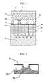
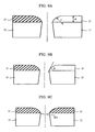
- FIGS. 8 and 9A to 9C are cross-sectional views of the nozzle plate of the inkjet head of the present invention.
- a nozzle plate 32 which is a base material of the inkjet head is produced by Ni electroforming, an ink repellent layer 31 that is a silicone resin film having a surface roughness (Ra) of preferably 0.2 ⁇ m or less.
- a meniscus (liquid surface) P is formed in a boundary portion of the ink repellent layer 31 composed of a silicon resin film and the nozzle plate 32.
- the ink repellent layer is so formed that a cross section area in a plane perpendicular to a central line of an opening of the ink repellant layer which is formed on the surface provided with opening (nozzle) for ink discharge in the inkjet head in the vicinity of the opening increases successively with distance from the surface of the base material.
- the ink repellent layer preferably has a curved surface shape in the vicinity of the opening. Further, the curvature radius of the curve of the ink repellent layer in the vicinity of the opening in the cross section of the plane including the central line of the opening is preferably equal to or more than the thickness of the ink repellent layer. Further, it is also preferred that the curve of the ink repellent layer from the edge of the opening to the vicinity of the opening in the cross section of the plane including the central line of the opening be a substantially circular-are curve, and the curvature radius of the circular arc is preferably equal to or more than the thickness of the ink repellent layer. A tangent line to the ink repellent layer passing through the edge of the opening in the cross section of the plane including the central line of the opening preferably forms an angle of less than 90 degrees with the nozzle member surface including the edge.
- the opening of the nozzle plate 32 is so provided that the cross section formed by the plane perpendicular to the central line represented by a dot-dash line in FIGS. 9A to 9C has a substantially round shape with this central line as a center. Further, the ink repellent layer 31 formed on the ink discharge surface in the nozzle plate 32 is formed such that the cross section area of the opening portion formed by the plane perpendicular to the central line increases successively with distance from the nozzle plate 32.
- the curve from the opening edge of the nozzle plate 32 in the vicinity of the opening has a round shape with a curvature radius "r".
- This curvature radius r is preferably equal to or more than the thickness d of the ink repellent layer 31 outside the zone in the vicinity of the open portion.
- the thickness "d” is a thickness of ink repellent layer 31 outside the round portion that is the open portion and preferably is the maximum thickness of the ink repellent layer.
- the open portion of the ink repellent layer 31 that is connected to the opening of the nozzle plate 32 has a shape without sharp edges (smooth curve without sharp portions) and is a curve having no protruding zones. Therefore, when it is wiped with a wiper formed from a material such as rubber, the ink repellent layer 31 can be prevented from being separated from the nozzle plate 32 as a result of sharp portions being caught by the wiper.
- a tangent line to the ink repellent layer 31 passing through the edge of the opening in the cross section along the plane including the central line of the opening of the nozzle plate 32 preferably forms an angle ⁇ of less than 90 degrees with the surface of the nozzle plate 32 including the opening edge of the nozzle plate 32 connected to the edge of the opening portion.
- a liquid silicone resin curable at room temperature is preferably used as the silicone resin used in the present embodiment and a resin of a type such that curing is accompanied by a hydrolysis reaction is even more preferred.
- SR2411 manufactured by Dow Corning Toray Co., Ltd.
- Table 1 shows the results obtained by evaluating the shape of the ink repellent layer 31 from the opening edge of the nozzle plate 32 to the vicinity of the opening edge in the inkjet head of the present embodiment and the occurrence of ink residue around the nozzle, edge separation, and discharge stability.
- Table 1 Edge shape Ink residue Edge separation Discharge stability Sharp tip is present Some ink residue occurs Occurs Good No sharp tip (round shape) ⁇ ⁇ 90° None None Good ⁇ > 90° None None Poor r ⁇ d None None Good r ⁇ d None Some edge separation occurs Poor
- a meniscus (liquid level) P can be formed in the boundary portion of the ink repellent layer 31 and nozzle plate 32 during ink filling and a meniscus Q can be formed in the convex portion (a portion in which the area of the cross section perpendicular to the central line in the open portion is the smallest) facing the center of the open portion of the ink repellent layer 31'.
- ink discharge stability may sometimes vary during image recording in the inkjet recording apparatus using the inkjet head including the nozzle plate 32.
- FIG. 11 shows a configuration in which an ink repellent layer 31 is formed by coating a silicone resin with a dispenser 34 of the present embodiment.
- the dispenser 34 is disposed for coating a silicone solution on the ink discharge surface side of the nozzle 32 produced by Ni electroforming, and the ink repellent layer 31 can be selectively formed on the ink discharge surface of the nozzle plate 32, as shown in the above-described FIG. 8 and FIGS. 9A to 9C , by scanning the dispenser 34, while discharging the silicone solution from the tip of a needle 35 and maintaining a predetermined constant spacing between the nozzle plate 32 and the tip of the needle 35.
- the silicone resin used in the present embodiment is a silicone resin curable at normal temperature (SR2411 manufactured by Dow Corning Toray Co., Ltd., and having a viscosity of 10 mPa ⁇ s). A certain accumulation of the silicone is observed in the nozzle hole and the back surface of the nozzle plate.
- the ink repellent layer 31 (silicone resin film) that is selectively formed in the above-described manner has a thickness of 1.2 ⁇ m and a surface roughness (Ra) of 0.18 ⁇ m.
- the coating orifice at the tip of the needle 35 of the present embodiment, as shown in FIG. 12A , is ensured to have a width equal to the coating width of the nozzle plate 32 which is the coating object.
- coating of the entire coating object can be completed by scanning the dispenser 34 once in the coating direction.
- the scanning direction for coating operation can be only one direction, and as shown in FIG. 12B the changing the direction to perform scanning in the opposite direction can be eliminated.
- the tip of the conventional needle 35 is much narrower than the coating width on the nozzle plate 32. Therefore, in order to complete scanning of the entire scanning object, it is necessary to perform scanning in a plurality of directions by changing the scanning direction for the coating operation by 90°, shifting the tip of the needle, and performing scanning in the opposite direction. As a result, a coating film having a uniform thickness is difficult to obtain on the entire coating object.
- the width of the coating orifice at the tip of the needle 35 is ensured to be equal to the coating width on the nozzle plate 32 which is the coating object, whereby a uniform coating thickness can be obtained over the entire coating object and the surface of the nozzle plate can be finished with good accuracy.
- FIG. 13 shows a coating operation using the dispenser 34 of the present embodiment.
- the basic configuration is identical to that shown in Fig. 11 , but a silicone solution is coated, while spraying gas 36 from a nozzle hole (opening) of the nozzle plate 32.
- the gas 36 a variety of gases which do not easily participate in chemical reaction with silicone to be coated may be used. For example, air can be used.
- the ink repellent layer 31 silicone resin film
- an ink repellent layer consisting of a silicone resin to a desired depth (for example, about several ⁇ m) on the inner wall of the nozzle, as shown in FIG. 14 .
- a very thin ink repellent layer 31a ink repellent layer on the inner wall of the opening
- Wiping is performed using an EPDM rubber (rubber hardness 50°) with respect to the ink repellent layer 31 of the nozzle plate produced in the above-described manner.
- the results obtained demonstrated that the ink repellent layer 31 of the nozzle plate can maintain good ink repellency with respect to 1,000 times of wiping.
- the nozzle member having the ink repellent layer formed thereof was immersed into ink at 70°C for 14 days. The results obtained demonstrated that unchanged ink repellency could be maintained even after the immersion.
- FIG. 15 shows an example of an inkjet head used in the present invention and shows a state where a nozzle hole is formed by an excimer laser processing.
- a nozzle plate 43 is obtained by joining a resin member 121 and a high-rigidity member 125 with a thermoplastic adhesive 126.
- a SiO 2 thin-film layer 122 and a fluorine-containing water-repellent layer 123 are successively laminated on the surface of the resin member 121, a nozzle hole 44 of a required diameter is formed in the resin member 121, and a nozzle linking orifice 127 that is linked to the nozzle hole 44 is formed in the high-rigidity member 125.
- the SiO 2 thin-film layer 122 is formed by a method that produces a relatively small amount of heat, that is, at a temperature within a range in which the resin member is not thermally affected. More specifically, the preferred methods include sputtering, ion-beam vapor deposition, ion plating, CVD (chemical vapor deposition), and P-CVD (plasma chemical vapor deposition).
- the thickness of the SiO 2 thin-film layer 122 be the minimum required thickness within a range in which the adhesive strength is ensured. This is because if the thickness is too large, it sometimes hinders the formation of nozzle hole with the excimer laser. Thus, in some cases part of the SiO 2 thin-film layer 122 is not sufficiently processed and an un-processed section remains even if a good nozzle hole shape is obtained in the resin member 121. Therefore, it can be said that the suitable thickness is within a range of 1 ⁇ to 300 ⁇ (0.1 nm to 30 nm) in which good adhesive strength can be ensured and no SiO 2 thin-film layer 122 remains during excimer laser processing.
- An even more preferred range is 10 ⁇ to 100 ⁇ (1 nm to 10 nm).
- Test results demonstrated that even at a SiO 2 film thickness of 30 ⁇ (3 nm) sufficient adhesivity is obtained and no problems are associated with excimer laser processability. Further, extremely small processing residues are observed at a film thickness of 300 ⁇ (30 nm), and rather large processing residues are generated when the thickness exceeds 300 ⁇ (30 nm), these residues creating an abnormal nozzle shape that cannot be used.
- Fig. 16 shows an example of a configuration of an excimer laser processing apparatus for use in nozzle hole formation.
- An excimer laser beam 82 emitted from a laser generator 81 is reflected by mirrors 83, 85, 88 and guided to a processing table 90.
- a beam expander 84, a mask 86, a field lens 87, and an image-forming optical system 89 are provided in the predetermined positions of an optical path by which the laser beam 82 reaches the processing table 90 in order to obtain a laser beam optimal for a specific processing object.
- a processing object (nozzle plate) 91 is placed on the processing table 90 and receives the laser beam.
- the processing table 90 is a well-known XYZ table that is configured, if necessary, so that the processing object 91 can be moved to be irradiated with the laser beam in a desired position.
- the use of an excimer laser is explained herein, but a variety of lasers can be used, provided that they are short-wavelength UV lasers enabling the ablation processing.
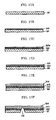
- Fig. 17A to Fig. 17F schematically show a process for producing a nozzle plate in the method for producing the inkjet head used in the present invention.
- Fig. 17A shows a material serving as a base material for a nozzle forming member.
- a powder-free film of Kapton which is a polyimide film manufactured by DuPont, is used as the resin film 121.
- particles such as SiO 2 (silica) are added to the film material to improve handleability (sliding ability) in a roll film handling apparatus.
- Fig. 17B shows a step in which the SiO 2 thin-film layer 122 is formed on the surface of the resin film 121.
- a sputtering method performed in a vacuum chamber is suitable for forming the SiO 2 thin-film layer 122.
- the appropriate film thickness of the thin-film layer 122 is several angstroms to 200 ⁇ (20 nm).
- the SiO 2 thin-film layer 122 having a thickness of 10 ⁇ to 50 ⁇ (1 nm to 5 nm) is formed.
- a sputtering method in which Si is sputtered and then a SiO 2 film is formed by bombarding the Si surface with O 2 ions is effective in terms of improving the adhesive strength of the SiO 2 film to the resin film 121, obtaining a homogeneous dense film, and improving wiping endurance of the water repellent film.
- Fig. 17C shows a step in which a fluorine-containing water repellent agent 123a is coated over a surface of a SiO 2 thin-film layer 122.
- a method employing a spin coater, a roll coater, screen printing, or a spray coater can be used for coating the fluorine-containing water repellent agent, but a method for forming the film by vapor deposition is more effective because it improves adhesivity of the water-repellent film.
- An even better effect can be obtained with vacuum deposition by performing vacuum deposition in a vacuum chamber directly after forming the SiO 2 thin-film layer 122 as shown in Fig. 17B .
- the workpiece is removed from the vacuum chamber once the SiO 2 thin-film layer 122 has been formed.
- impurities or the like adhere to the workpiece surface, thereby degrading adhesion.
- a variety of materials are known as fluorine-containing water repellent materials.
- water repellency necessary with respect to the ink can be obtained by using perfluoropolyoxetane, modified perfluoropolyoxetane, a mixture thereof as a fluorine amorphous compound.
- the aforementioned Optool DSX, manufactured by Daikin Industries, Ltd. is called "an alkoxysilane-terminated modified perfluoropolyether.”
- Fig. 17D shows a step of allowing the deposited water repellent film to stand in the air.
- the fluorine-containing water-repellent agent 123a and the SiO 2 thin-film layer 122 are chemically bonded via moisture present in the air and the fluorine-containing water-repellent layer 223 is formed.
- Fig. 17E shows a step of pasting the adhesive tape 124.
- the adhesive tape 124 is attached on the surface coated with the fluorine-containing water repellent layer 123.
- the adhesive tape 124 is attached so that no gas bubbles are generated. Where gas bubbles are generated, quality of the nozzle hole opened in a location where a gas bubble is present is sometimes degraded by the adhesion of foreign matter during processing.
- Fig. 17F shows a step of forming the nozzle hole 44.
- the nozzle hole 44 is formed by irradiating with an excimer laser from the side of the polyimide film 121.
- the adhesive tape 124 is peeled off.
- the explanation of the high-rigidity member 125 used to improve the rigidity of the nozzle plate 43 that is explained with reference to Fig. 15 is omitted, but where the high-rigidity member is applied, the step is implemented between the step shown in Fig. 17D and the step shown in Fig. 17E .
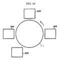
- Fig. 18 schematically shows an apparatus used in producing an inkjet head by the method for producing the inkjet head used in the present invention.
- This apparatus implements the so-called "metamode process” developed by Optical Coating Laboratory Inc. (OCLI, USA), and used for producing antireflective films and contamination-preventing films for displays or the like.
- a Si sputter 202, an O 2 ion gun 203, a Nb sputter 204, and an Optool deposition unit 205 are disposed as stations in four locations around a drum 210, and the entire configuration is disposed in an evacuated chamber.
- Si is sputtered with the Si sputter 202, and then SiO 2 is obtained by bombarding the Si with O 2 ions with the O 2 ion gun 203.
- Nb and Optool DSX are then appropriately vapor deposited with the Nb sputter 204 and Optool deposition unit 205.
- vapor deposition is performed after Nb and SiO 2 are stacked to obtain the necessary number of layers of a predetermined thickness.
- the function of antireflective film is not required. Therefore, Nb is not necessary, and SiO 2 and Optool DSX may be deposited by one layer each.
- the ink repellent layer has a critical surface tension of preferably 5 mN/m to 40 mN/m, and more preferably 5 mN/m to 30 mN/m.
- a critical surface tension exceeds 30 mN/m, a phenomenon by which the nozzle plate is over-wetted with the ink in long-term use occurs.
- curving of ink discharge trajectory or abnormal formation of ink droplets sometimes occurs in repeated printing.
- the critical surface tension exceeds 40 mN/m the over-wetting of the nozzle plate occurs from the beginning, whereby curving of ink discharge trajectory or abnormal formation of ink droplets sometimes occurs from the beginning.
- the ink repellent material shown in Table 2 is coated on an aluminum board and dried by heating to produce a nozzle plate having an ink repellent layer. Results obtained in measuring the critical surface tension of the ink repellent layer are shown in Table 2.
- the critical surface tension can be found by a Zisman method.
- a liquid having a known surface tension is dropped on the ink repellent layer, a contact angle ⁇ is measured, and a line descending to the right (Zisman Plot) is obtained by plotting the surface tension of the liquid against the x axis and cos ⁇ against the y axis.
- Examples of other methods suitable for finding the critical surface tension include a Fowkes method, an Owens and Wendt method, and a Van Oss method.
- an inkjet head is produced by using the nozzle plate having an ink repellent layer.
- the below-described cyan ink is sprayed thereonto.
- the jetting process of the ink is videotaped and observed.
- accurate atomization and excellent discharge stability are confirmed. The results are shown in Table 2.
- An appropriate quantity of ion-exchanged water is added to 20.0% by mass of polymer ultrafine particle dispersion containing a copper phthalocyanine pigment, 23.0% by mass of 3-methyl-1,3-butanediol, 8.0% by mass of glycerin, 2.0% by mass of 2-ethyl-1,3-hexanediol, 2.5% by mass of FS-300 (manufactured by DuPont) as a fluorine-containing surfactant, 0.2% by mass of Proxel LV (manufactured by Avecia Co., Ltd.) as an antiseptic/antifungal agent, and 0.5% by mass of 2-amino-2-ethyl-1,3-propanediol to obtain 100% by mass, and then filtration is performed with a membrane filter having a pore diameter of 0.8 ⁇ m.
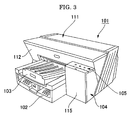
- An inkjet recording apparatus shown in FIG. 3 contains an apparatus body 101, a paper feed tray 102 which serves to load papers and is mounted on the apparatus body 101, a paper discharge tray 103 which serves for stocking papers on which images have been recorded (formed) and is mounted on the apparatus body 101.
- the top surface of an upper cover 111 in the apparatus body 101 is substantially flat, a front surface 112 of a front cover in the main apparatus body 101 slants obliquely backward relative to a top surface, and below the slanted front surface 112, forwardly (front side) projecting paper discharge tray 103 and paper feed tray 102 are located.
- an ink cartridge loading unit 104 forwardly projects from the front surface 112 in a position of lower than the upper cover 111, and a control panel 105 containing control keys and a display is disposed on the upper surface of the ink cartridge loading unit 104.
- the ink cartridge loading unit 104 has a front cover 115 that can open and close for detachably mounting an ink cartridge.
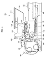
- a carriage 133 is supported so that it can slide in the main scanning direction by a guide rod 131 and a stay 132 that are guide members extending in the transverse direction between left and right side plates (not shown), and the cartridge can be moved for scanning in the direction shown by an arrow in FIG. 5 by a main scanning motor (not shown).
- a recording head 134 composed of four inkjet heads discharge ink droplets of yellow, cyan, magenta, and black colors is equipped so that a plurality of ink discharge ports are arranged in the direction perpendicular to the main scanning direction and the ink droplet discharge directions face downward.
- a head constituting the recording head 134 which contains a piezoelectric actuator such as a piezoelectric element, a thermal actuator that utilizes phase transition caused by film boiling of a liquid by using a thermoelectric conversion element such as an exothermic resistive element, a shape-memory-alloy actuator that utilizes metal phase transition caused by temperature variations, or an electrostatic actuator using electrostatic forces as an energy generating unit for discharging ink, can be used.
- the carriage 133 carries sub-tanks 135 for supplying with inks of each color to the recording head 134.
- the sub-tank 135 is supplied with the ink of the present invention via an ink supply tube (not shown) from the ink cartridge that is loaded into the ink cartridge loading unit 104.
- a half-moon roller (paper feed roller) 143 that can feed papers 142 sheet by sheet from a paper loading unit (pressure plate) 141 and a separation pad 144 facing the paper feed roller 143 and made from a material with a high friction coefficient are provided as a paper feed unit for feeding paper 142 that was loaded on the paper loading unit (pressure plate) 141 of the paper feed tray 102, and the separation pad 144 is biased toward the paper feed roller 143.
- a conveying belt 151 for electrostatically attracting the paper 142 and conveying it, a counter roller 152 for conveying the paper 142 conveyed from the paper feed unit via a guide 145 between the counter roller and the conveying belt 151, a conveying guide 153 that converts the direction of the paper 142 that is fed substantially vertically upward by substantially 90° to align the paper with the conveying belt 151, and a tip pressurization roller 155 that is biased toward the conveying belt 151 with a pushing member 154 are provided as a conveying unit for conveying the paper 142 fed from the paper feed unit below the recording head 134.
- a charging roller 156 is provided as a charging unit for charging the surface of the conveying belt 151.
- the conveying belt 151 is an endless belt that is stretched between a conveying roller 157 and a tension roller 158 and can rotate in the belt conveying direction.
- the conveying belt 151 for example, has a surface layer serving as a paper attraction surface that is formed from a resin material having a thickness of about 40 ⁇ m, which resistance is not controlled, for example, a surface layer consisting of tetrafluoroethylene and ethylene (ETFE) and a back layer (medium resistance layer, ground layer) that is made from the same material as the surface layer, which resistance is controlled by carbon.
- a guide member 161 is disposed opposite a printing region created by the recording head 134 on the rear side of the conveying belt 151.
- a separation hook 171 for separating the paper 142 from the conveying belt 151, a paper discharge roller 172, and a paper discharge roller 173 are provided as a paper discharge unit for discharging the paper 142 that has been recorded in the recording unit 134.
- the paper discharge tray 103 is disposed below the paper discharge roller 172.
- the inkjet recording apparatus and inkjet recording method of the present invention can be applied to various recording systems by the inkjet recording method, and can be particularly advantageously applied to inkjet recording printers, facsimile machines, copiers, and printer-fax-copier machines.
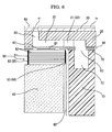
- FIG. 6 shows an enlarged sectional view of an example of an inkjet head of the present invention.
- FIG. 7 shows an enlarged sectional view of an example of the main portion of an inkjet head of the present invention.
- the inkjet head contains a frame 10 having formed therein a cavity serving as an ink supply port and a common liquid chamber 12, a flow path 20 having formed therein a cavity serving as a resistance portion 21 and a pressurized liquid chamber 22 and a link port 23 linked to a nozzle 41, a nozzle plate 30 forming the nozzle 41, an oscillation plate 60 having a convex portion 61, a diaphragm portion 62 and an ink inflow port 63, a laminated piezoelectric element 50 joined with an adhesive layer 70 to the oscillation plate 60, and a base 40 that fixes the laminated piezoelectric element 50.
- the base 40 is made from a barium titanate ceramic and has two laminated piezoelectric elements 50 disposed in row and joined thereto.
- the laminated piezoelectric element 50 is obtained by alternately laminating piezoelectric layers 51 of lead zirconium titanate (PZT), each having a thickness of 10 ⁇ m to 50 ⁇ m, and internal electrode layers 52 composed of silver-palladium (AgPd), each layer having a thickness of several micrometers.
- the internal electrode layers 52 are connected to the external electrodes 53 at both ends.
- the laminated piezoelectric element 50 is split in a combtooth manner by half-cut dicing, and each section is used as a drive portion 56 and a support portion 57 (non-drive portion) (see FIG. 7 ).
- the external side of one of two external electrodes 53 is restricted in length by machining such as notching so that it can be split by half-cut dicing, and the sections obtained serve as a plurality of individual electrodes 54.
- the other side is conductive, without being split by dicing, and serves as a common electrode 55.
- An FPC 80 is joined by soldering to individual electrodes 54 of the drive portion. Further, in the common electrode 55, an electrode layer is provided at the end portion of the laminated piezoelectric element 50 and bent to joint to the ground electrode of the FPC 80.
- a Driver IC (not shown) is mounted on the FPC 80, and drive voltage application to the drive portion 56 is controlled thereby.
- the oscillation plate 60 is formed from the thin-film diaphragm portion 62, the island-shaped convex portion (island portion) 61 that is formed in the central zone of the diaphragm portion 62, joined to the laminated piezoelectric element 50 and serves as the drive portion 56, a thick-film portion including a beam for connection to the support portion (not shown), and an opening serving as the ink inflow port 63, by two-layer stacking a Ni plated film obtained by an electroforming method.
- the thickness of the diaphragm portion is 3 ⁇ m and the width is 35 ⁇ m (one side).
- a silicon single-crystal substrate is used for the flow path plate 20, and the plate is patterned by an etching method to form a cavity serving as the fluid resistance portion 21 and pressurized fluid chamber 22 and a through port serving as the link port 23 in a position corresponding to the nozzle 41.
- a portion remaining after etching serves as a partition wall 24 of the pressurized fluid chamber 22.
- a portion of decreased etching width is provided in the head, and this portion serves as the fluid resistance portion 21.
- the nozzle plate 30 is formed of a metal material, e.g., of a Ni plated film obtained by electroforming and has a large number of nozzles 41 serving as fine discharge ports for inkjet ink droplets.
- the nozzles 41 are formed to have a horn-like inner (internal) shape (may also have a substantially cylindrical rod-like or barrel-like shape).
- the diameter of the nozzle 41 is 20 ⁇ m to 35 ⁇ m, as a diameter on the ink droplet discharge port.
- the nozzle pitch in each row is 150 dpi.
- the ink discharging surface (nozzle surface) of the nozzle plate 30 has an ink repellent layer 71.
- a water-repellency treated layer according to the properties of ink is formed by a method, such as
- the ink repellent layer 71 is composed of a composition containing a silicone resin and/or a fluorine resin.
- the composition containing a silicone resin and/or a fluorine resin is composed of a silicone resin alone, a fluorine resin alone, and of mixture of a silicone resin and components such as another resin, metal and the like.
- examples thereof include a composition in which silicone resin fine particles are dispersed in a fluorine resin, a kneaded product of a silicone resin and polypropylene, and a product obtained by eutectoid plating of a silicone resin and Ni.
- a mixture of a silicone resin and other components other than silicone resins are more effectively used.
- the ink pressure inside the pressurized liquid chamber 22 is reduced, a negative pressure is generated inside the pressurized liquid chamber 22 by the inertia of ink flow and discharge process of the drive pulse, and then a transition is made to an ink filling step.
- the ink supplied from the ink tank flows into the common liquid chamber 12, and the pressurized liquid chamber 22 is filled with the ink from the common liquid chamber 12 via the ink inflow port 63 and through the fluid resistance portion 21.
- the fluid resistance portion 21 effectively attenuates residual pressure oscillations after discharging and also creates resistance to a refill by surface tension.
- An ink record according to the present invention is recorded by means of the inkjet recording apparatus and the inkjet recording method of the present invention.
- the ink record according to the present invention has an image formed on a recording medium using the inkjet ink of the present invention.
- the recording medium is not particularly limited and may be appropriately selected according to the purpose. Examples thereof include a regular paper, gloss paper, special paper, fabric, film, and OHP sheet. These recording media may be used alone or in combination.
- the ink records have a high image quality with less ink bleed and excel in temporal stability, and thus the ink records may be suitably used for various purposes as documents on which various printing and/or images are recorded.
- the present invention can solve the problems in conventional technologies and provide an inkjet ink capable of being prevented from fixation to a nozzle plate having an ink repellent layer containing a silicone resin and excellent in discharge stability, an ink cartridge, inkjet recording method, inkjet recording apparatus, and ink record using the inkjet ink.
- the pigments and dispersants shown in Table 3 were respectively mixed with water, and then dispersed for 2 hours using zirconia beads having a diameter of 0.3 ⁇ m in DYNO-MILL (by SHINMARU ENTERPRISES CORPORATION). Subsequently, the zirconium beads and liquid were separated to prepare pigment dispersions A to C (pigment concentration of 15% and dispersant concentration of 3.75%).
- the self-dispersible pigment, CAB-O-JET300 (manufactured by CABOT Corporation) of D is a pigment in which a carbon black surface is modified with a diazonium salt having a -COONa group.
- ⁇ a fluorine surfactant, FS-300 (manufactured by DuPont) expressed by General Formula (2): CF 3 CF 2 (CF 2 CF 2 ) m -CH 2 CH 2 O(CH 2 CH 2 O) n H General Formula (2) where m is 6 to 8 and n is 26 or more.
- ⁇ a fluorine surfactant, PF-151N (manufactured by OMNOVA Solutions Inc.) expressed by General Formula (3): where n is 4, m is 21, p is 4 and Rf is CF 2 CF 3 .
- Y a fluorine surfactant, FSN-100 (manufactured by DuPont) expressed by General Formula (2): CF 3 CF 2 (CF 2 CF 2 ) m -CH 2 CH 2 O(CH 2 CH 2 O) n H General Formula (2) where m is 1 to 9 and n is 0 to 25.
- ⁇ a fluorine surfactant, PF-156A (manufactured by OMNOVA Solutions Inc.) expressed by General Formula (4): where, q is 6 and Rf is CF 2 CF 3 .
- TMS tetramethylsilane
- solvents such as DMSO, DMF-d7, THF-d8, acetone-d6, methanol-d4, heavy water and hexane-d14 used in this order. The solvent which firstly dissolved the sample was used.
- the ink formulations (100 parts in total) shown in Table 7 were prepared, and then filtrated through a filter having a pore diameter of 0.8 ⁇ m to prepare respective inkjet inks. Each ink was subjected to vacuum deaeration and an ink bag for IPSIO GX 3000 (manufactured by Ricoh Company, Ltd.) was filled therewith to prepare an ink cartridge.
- Table 7 Pigment dispersion or dye Water-soluble organic solvent Resin emulsion 1 Resin emulsion 2 Surfactant Silicone oil Water Ink 1 A(40.0 parts) diethylene glycol (20.0 parts) b(2.0 parts) c(5.0 parts) ⁇ (2.0 parts) U(1.0 part) q.s.
- Ink 9 A(40.0 parts) glycerin (10.0 parts) b (5.0 parts) - ⁇ (0.5 parts) T(0.5 parts) q.s.
- Ink 10 D(50.0 parts) glycerin (10.0 parts) - c (5.0 parts) ⁇ (1.0 part) U(1.0 part) q.s.
- Ink 11 E(4.0 parts) glycerin (10.0 parts) - c (5.0 parts) ⁇ (1.0 part) W(1.0 part) q.s.
- Comparative Ink 1 A(40.0 parts) diethylene glycol(20.0 parts) b (2.0 parts) c (5.0 parts) ⁇ (2.0 parts) - q.s.
- the surface tensions of the prepared inkjet inks were respectively measured under the following conditions.
- a silicone resin, SR2411 (by Dow Corning Toray Co., Ltd.) was coated on a surface of an electroformed Ni nozzle by a dispenser to form a silicone layer.
- the silicone layer was formed in such a manner that firstly nozzle holes and the back surface of a nozzle plate were masked with a water soluble resin, and the mask was removed therefrom. This was left to stand for 2 days at room temperature so as to cure, thereby forming an ink repellent layer having a thickness of 1.2 ⁇ m.
- the obtained ink repellent layer had a surface roughness Ra of 0.18 ⁇ m and a critical surface tension of 21.6 mN/m.
- the thickness of the ink repellent layer was measured using a spectrometric film thickness measurement system, LAMBDA-ACE VM-8000J (manufactured by DAINIPPON SCREEN MFG Co., Ltd.).
- the surface roughness of the ink repellent layer was measured using a stylus profiler for surface roughness measurement, Dektak3-ST (by Veeco Instruments).
- the critical surface tension of the ink repellent layer was measured by Zisman method.
- An ink repellent layer having a thickness of 1.0 ⁇ m formed on a nozzle plate was produced in the same manner as in Production Example 1, except that the silicone resin, SR2411 (by Dow Corning Toray Co., Ltd.) in Production Example 1 was changed to a silicone resin, KBM7803 (Shin-Etsu Chemical Co., Ltd.).
- the ink repellent layer was measured in the same manner as in Production Example 1, and had a surface roughness Ra of 0.22 ⁇ m and a critical surface tension of 0.17 mN/m.
- the thickness of the ink repellent layer was measured on an atomic force microscope, NaNO-I (manufactured by TOYO Corporation).
- the surface roughness Ra and critical surface tension of the ink repellent layer were respectively 0.01 ⁇ m and 11.8 mN/m by measuring in the same manner as in Production Example 1.
- a nozzle plate was produced in the same manner as in Production Example 1, except that the ink repellent layer consisting of a silicone resin was not formed on the surface of the electroformed Ni nozzle.
- the printer was placed in a constant temperature and humidity room, the temperature of the inside was adjusted at 32°C and 30%RH.
- the following pattern chart was continuously printed on 20 sheets and then not printed (in a resting state) for 20 minutes. This process was repeated 50 times and 1,000 sheets were printed in total, and then the nozzle plate was observed on a microscope and evaluated on the presence or absence of fixation.
- a pattern was printed using a chart having a print area of each color of 5% in whole area of a sheet surface with 100% duty of each color ink under the printing conditions of a recording density of 300 dpi and one pass printing.
- Example 9 Images of Examples 2 to 11 and Comparative Examples 1 to 10 were printed in the same manner as in Example 1, except that the inkjet printer respectively using the combinations of the inks and nozzle plates shown in Table 9 was used. And then, the discharge stability was evaluated in the same manner as in Example 1. The results are shown in Table 9.
- Example 9 Ink Nozzle plate Discharge stability (fixation state) Example 1 Ink 1 1 A Example 2 Ink 2 1 A Example 3 Ink 3 1 A Example 4 Ink 4 2 A Example 5 Ink 5 2 A Example 6 Ink 6 2 A Example 7 Ink 7 3 A Example 8 Ink 8 3 A Example 9 Ink 9 3 A Example 10 Ink 10 1 A Example 11 Ink 11 1 A Comparative Example 1 Comparative Ink 1 1 B Comparative Example 2 Comparative Ink 2 1 B Comparative Example 3 Comparative Ink 3 1 B Comparative Example 4 Comparative Ink 4 2 B Comparative Example 5 Comparative Ink 5 2 B Comparative Example 6 Comparative Ink 6 2 B Comparative Example 7 Comparative Ink 7 3 B Comparative Example 8 Comparative Ink 8 3 B Comparative Example 9 Comparative Ink 9 3 B Comparative Example 10 Ink 1 4 B
- the inkjet ink of the present invention can be prevented from fixation to an ink repellent layer and excellent in discharge stability, thereby suitably used for an inkjet recording method and an inkjet recording apparatus.
- the inkjet recording apparatus and inkjet recording method of the present invention can be applied to various recording systems by the inkjet recording method, and can be particularly advantageously applied to inkjet recording printers, facsimile machines, copiers, and printer-fax-copier machines.
Landscapes
- Chemical & Material Sciences (AREA)
- Life Sciences & Earth Sciences (AREA)
- Engineering & Computer Science (AREA)
- Materials Engineering (AREA)
- Wood Science & Technology (AREA)
- Organic Chemistry (AREA)
- Inks, Pencil-Leads, Or Crayons (AREA)
- Ink Jet Recording Methods And Recording Media Thereof (AREA)
Abstract

Description
- The present invention relates to an inkjet ink suitably used for image recording by an inkjet method, and an ink cartridge, inkjet recording method, inkjet recording apparatus and ink record using the inkjet ink.
- Inkjet recording has advantages over other recording methods in that it facilitates full-colorization because of the process that is simpler than those of other recording methods and in that high-resolution images can be obtained even with a simply configured apparatus.
- Recently, demands for image quality, color phase, color saturation, glossiness, and durability (scratch resistance, marker resistance and the like) become more exacting in association with technical improvement in OA printers for speed-up and higher image quality.
- In order to accomplish high image quality using a regular paper, it is effective to decrease the surface tension of an ink and to increase wettability to the regular paper so as to increase color developing property. Furthermore, a water insoluble resin can be effectively added to an ink to improve image durability.
- For example, Japanese Patent Application Laid-Open (JP-A) No.
2003-226827 - Additionally,
JP-A No. 2004-10733 JP-A No. 2004-10733 JP-A No. 2004-10733 JP-A No. 2004-10733 -
JP-A 2007-154021 - Therefore, the inventors of the present invention proposed adding a silicone resin in an ink repellent layer of a nozzle plate in an inkjet nozzle so as to decrease a surface tension of an inkjet ink and increase wettability to a recording medium, thereby increasing color development property (
JP-A No. 2005-138383 JP-A No. 2005-138383 -
JP-A No. 2008-95089 - An object of the present invention is to provide an inkjet ink capable of being prevented from fixation to an ink repellent layer and is excellent in discharge stability, and an ink cartridge, inkjet recording method, inkjet recording apparatus, and ink record using the inkjet ink.
- The present invention is based on the aforementioned finding made by the inventors, and means for solving the above-described problems are described below.
- <1> An inkjet ink containing at least a colorant, water, a water insoluble resin, a fluorine surfactant, and a polyether-modified silicone oil, wherein the polyether-modified silicone oil has a hydrophobic value of 0.40 to 1.5, and the hydrophobic value is expressed by Equation 1:

where "A" represents an integration value of a peak area from 0 ppm to 0.3 ppm in a 1H-NMR spectrum of the polyether-modified silicone oil using tetramethylsilane as a reference substance; and "B" represents an integration value of a peak area from 3.5 ppm to 4.0 ppm in the 1H-NMR spectrum. - <2> The inkjet ink according to <1>, wherein the colorant is a pigment dispersion in which a pigment is dispersed with any one of a nonionic surfactant and an anionic surfactant.
- <3> The inkjet ink according to <2>, wherein the nonionic surfactant is at least one of compounds expressed by General Formula (1):

- <4> The inkjet ink according to <1>, wherein the colorant is a self-dispersible pigment.
- <5> The inkjet ink according to <1>, wherein the colorant is a dye.
- <6> The inkjet ink according to any one of <1> to <5>, wherein the fluorine surfactant contains a compound expressed by General Formula (2)
CH3CF2(CF2CF2)m-CH2CH2O(CH2CH2O)nH General Formula (2)
where, "m" is an integer of 0 to 10, and "n" is an integer of 0 to 40. - <7> The inkjet ink according to any one of <1> to <5>, wherein the fluorine surfactant contains a compound expressed by General Formula (3):

- <8> The inkjet ink according to any one of <1> to <5>, wherein the fluorine surfactant contains a compound expressed by General Formula (4):

- <9> The inkjet ink according to any one of <1> to <8>, wherein the water insoluble resin is a resin emulsion.
- <10> The inkjet ink according to <9>, wherein the resin emulsion contains at least one selected from a polyurethane resin emulsion, styrene-acrylic resin emulsion, acryl-silicone resin emulsion and fluorine resin emulsion.
- <11> The inkjet ink according to <10>, wherein the polyurethane resin emulsion is an anionic self-emulsifiable ether polyurethane resin emulsion.
- <12> An inkjet recording method including jetting an inkjet ink from an inkjetting unit so as to record an image on a recording medium by applying a stimulus to the inkjet ink according to any one of <1> to <11>, wherein the inkjetting unit contains a recording head whose surface provided with an opening for ink discharge has an ink repellent layer.
- <13> The inkjet recording method according to <12>, wherein the ink repellent layer is composed of any one of a fluorine material and silicone material.
- <14> The inkjet recording method according to any one of <12> to <13>, wherein the ink repellent layer has a surface roughness Ra of 0.2 µm or less.
- <15> The inkjet recording method according to any one of <12> to <14>, wherein the ink repellent layer is so formed that a cross section area in a plane perpendicular to a central line of an opening of the ink repellant layer, which is formed on the surface provided with the opening for ink discharge in the recording head, in the vicinity of the opening increases successively with distance from the surface of the base material.
- <16> The inkjet recording method according to any one of <12> to <15>, wherein the ink repellent layer has a critical surface tension of 5 mN/m to 40 mN/m.
- <17> An inkjet recording apparatus containing an inkjetting unit configured to jet an inkjet ink so as to record an image on a recording medium by applying a stimulus to the inkjet ink according to any one of <1> to <11>, wherein the stimulus is at least one selected from heat, pressure, vibration and light.
- <18> An ink cartridge containing a container which contains the inkjet ink according to any one of <1> to <11>.
- <19> An ink record containing an image recorded on a recording medium by using the inkjet ink according to any one of <1> to <11>.
- An inkjet ink of the present invention contains at least a colorant, water, a water insoluble resin, a fluorine surfactant and a polyether-modified silicone oil, wherein the polyether-modified silicone oil has a hydrophobic value of 0.40 to 1.5 as measured using a 1H-NMR spectrum of the polyether-modified silicone oil using tetramethylsilane (TMS) as a reference substance, and the hydrophobic value is expressed by the above Equation 1.
- Because a perfluoroalkyl group has oil repellency in the fluorine surfactant contained in the inkjet ink of the present invention, the ink containing the fluorine surfactant has excellent releasability to the ink repellent layer, in which lipophilic groups are attached to the surface thereof. Thus, it is considered that the ink fixation to the ink repellent layer containing a silicone resin is caused due to drying of the colorant and water insoluble resin in the ink.
- Therefore, the hydrophilic-lipophilic balance of the polyether-modified silicone oil which is added to the ink is focused on and studied, and it is found that, particularly, a hydrophobic value correlates with ink fixation to an ink repellent layer, and that the ink fixation to the ink repellent layer can be prevented by adjusting the hydrophobic value of the polyether-modified silicone oil to 0.40 to 1.5. Generally, hydrophilic-lipophilic balance is discussed in terms of an HLB value, however, the ink fixation to an ink repellent layer is not correlated with an HLB value, and cannot be explained only in terms of an HLB value (see Table 6). When the hydrophobic value is 0.40 to 1.5, the proportion of hydrophobic sites in the silicone oil is increased, allowing the silicone oil to be easily adsorbed on a water insoluble resin. Thus, hydrophilization of the surface of the water insoluble resin prevents the ink from fixation to an ink repellent layer, thereby improving discharge stability. When the hydrophobic value is less than 0.40, the silicone oil is not sufficiently adsorbed on a water insoluble resin, thereby causing ink fixation to the ink repellent layer. When the hydrophobic value is more than 1.5, the proportion of hydrophilic sites is relatively decreased, thus a surface of the water insoluble resin is not sufficiently hydrophilized, and does not exhibit the effect of preventing the ink from fixation.
- An inkjet recording apparatus of the present invention contains at least an inkjetting unit configured to jet the inkjet ink of the present invention so as to record an image on a recording medium by applying stimulus (energy) to the inkjet ink, and the stimulus is at least one selected from heat, pressure, vibration and light. In the inkjet recording apparatus, the inkjetting unit applies energy to the inkjet ink of the present invention so as to jet the inkjet ink for recording an image, thereby obtaining discharge stability and high quality images.
- An inkjet recording method of the present invention is an inkjet recording method including jetting an inkjet ink from an inkjetting unit so as to record an image on a recording medium by applying a stimulus to the inkjet ink according to any one of <1> to <11>, wherein inkjetting unit contains a recording head whose surface provided with an opening for ink discharge has an ink repellent layer, thereby obtaining discharge stability and high quality images.
- The ink cartridge used in the present invention contains a container which contains the inkjet ink of the present invention. The ink cartridge is suitably used for a printer and the like using the inkjet recording method. Recording is performed using the inkjet ink contained in the ink cartridge, thereby obtaining discharge stability and high quality images.
- The ink record according to the present invention contains an image recorded on a recording medium by using the inkjet ink of the present invention. The ink record according to the present invention can maintain high quality images having excellent color tone on various recording media.
-
-
FIG. 1 shows a schematic view of an example of an ink cartridge used in the present invention. -
FIG. 2 shows a schematic view of an example of an ink cartridge including a case (housing) shown inFIG. 1 -
FIG. 3 shows a perspective explanatory view of an example of an inkjet recording apparatus of the present invention. -
FIG. 4 shows a schematic view illustrating an example of an entire configuration of an inkjet recording apparatus of the present invention. -
FIG. 5 shows a schematic enlarged view of an example of an inkjet head of the present invention. -
FIG. 6 shows an enlarged sectional view of an example of an inkjet head of the present invention. -
FIG. 7 shows an enlarged sectional view of an example of the main portion of an inkjet head of the present invention. -
FIG. 8 shows a cross-sectional view of an example of a nozzle plate of the inkjet head of the present invention. -
FIG. 9A shows a schematic explanatory view of an example of a nozzle plate of an inkjet head of the present invention. -
FIG. 9B shows a schematic explanatory view of another example of a nozzle plate of an inkjet head of the present invention. -
FIG. 9C shows a schematic explanatory view of still another example of a nozzle plate of an inkjet head of the present invention. -
FIG. 10A shows a schematic explanatory view of an example of a nozzle plate of an inkjet head for comparison. -
FIG. 10B shows schematic explanatory view of another example of a nozzle plate of an inkjet head for comparison. -
FIG. 10C shows schematic explanatory view of still another example of a nozzle plate of an inkjet head for comparison. -
FIG. 11 shows a state in which an ink repellent layer is formed by coating a silicone resin using a dispenser. -
FIG. 12A shows a relation between a coating orifice at a tip of a needle and a coating width on a nozzle plate which is a coating object, according to the present invention. -
FIG. 12B shows a relation between a coating orifice at a tip of a needle and a coating width on a nozzle plate which is a coating object, according to a common technology. -
FIG. 13 shows a coating operation using a dispenser. -
FIG. 14 shows a state in which an ink repellent layer consisting of a silicone resin is formed in an inner wall of a nozzle in a desired depth. -
FIG. 15 shows an example of an inkjet head used in the present invention and shows a state where a nozzle hole is formed by an excimer laser processing. -
Fig. 16 shows an example of a configuration of an excimer laser processing apparatus for use in nozzle hole formation. -
Fig. 17A shows a material serving as a base material for a nozzle forming member. -
Fig. 17B shows a step in which a SiO2 thin-film layer is formed on a surface of a resin film. -
Fig. 17C shows a step in which a fluorine-containing water repellent agent is coated over a surface of a SiO2 thin-film layer. -
Fig. 17D shows a step of allowing the deposited water repellent film to stand in the air. -
Fig. 17E shows a step of pasting the adhesive tape. -
Fig. 17F shows a step of forming a nozzle hole. -
Fig. 18 schematically shows an example of an apparatus used - in producing an inkjet head by a method for producing the inkjet head.
- The inkjet ink of the present invention contains at least a colorant, water, water insoluble resin, fluorine surfactant and polyether-modified silicone oil, and contains a water-soluble organic solvent and penetrating agent, and further contains other components as necessary.
- The inkjet ink is used for an inkjet recording apparatus containing at least an inkjet head having an ink repellent layer as described later, and can be prevented from fixation to a nozzle plate having the ink repellent layer, and has a property excellent discharge stability.
- Polyether-Modified Silicone Oil-
- A polyether-modified silicone oil, which is contained in the inkjet ink, has a hydrophobic value of 0.40 to 1.5. The hydrophobic value is expressed by Equation 1:

where "A" represents an integration value of a peak area from 0 ppm to 0.3 ppm in a 1H-NMR spectrum of the polyether-modified silicone oil using tetramethylsilane (TMS) as a reference substance; and "B" represents an integration value of a peak area from 3.5 ppm to 4.0 ppm in the 1H-NMR spectrum. - Here, in the 1H-NMR spectrum the integration value of a peak area from 3.5 ppm to 4.0 ppm corresponds to the number of hydrogen atoms of a hydrophilic site such as polyoxyethylene, polyoxypropylene or the like in the polyether-modified silicone oil, and the integration value of a peak area from 0 ppm to 0.3 ppm corresponds to the number of hydrogen atoms of an alkyl group (hydrophobic site) bonded to Si element in the polyether-modified silicone oil. When the hydrophobic value, which is the ratio of the integration value of a peak area from 0 ppm to 0.3 ppm to the integration value of a peak area from 3.5 ppm to 4.0 ppm, is adjusted to 0.40 or more, the proportion of the hydrophobic sites in the silicone oil is increased. As a result, the silicone oil tends to be absorbed in the water insoluble resin, and thus the surface of the water insoluble resin is hydrophilized so as to be prevented from fixation to the ink repellent layer which has a hydrophobic surface.
- Note that the integration value does not include the integration values of peak areas in the spectra of tetramethylsilane (TMS) as a reference substance and spinning sideband of TMS.
- The hydrophobic value expressed by Equation 1 is preferably 0.40 to 1.5, and more preferably 0.40 to 1.2. When the hydrophobic value is less than 0.40, the silicone oil is not sufficiently adsorbed on a water insoluble resin, thereby causing ink fixation. On the other hand, when the hydrophobic value is more than 1.5, the proportion of hydrophilic sites is relatively decreased, thus a surface of the water insoluble resin is not sufficiently hydrophilized, and does not exhibit the effect of preventing the ink from fixation.
- Here, the 1H-NMR spectrum measurement is conducted using "JEOL JNM-A400FT NMR SYSTEM" (manufactured by JEOL Ltd.) under the following conditions: sample concentration = 1 % by mass; solvent: deuterated chloroform (CDCl3); the number of integration = 128; and temperature: room temperature. When the sample does not have sufficient solubility, solvents such as DMSO, DMF-d7, THF-d8, acetone-d6, methanol-d4, heavy water and hexane-d14 may be used in this order. The solvent which firstly dissolves the sample is used. The hydrophobic value is indicated by rounding off a measured value to two decimal places.
- Such a polyether-modified silicone oil has a polyoxyalkylene group, which is an adduct of ethylene oxide and propylene oxide, at a side chain of dimethyl polysiloxane, and commercially available one can be used. Examples of the commercially available polyether-modified silicone oils include DOW CORNING TORAY L-7604 (by Dow Corning Toray Co., Ltd.), and KF-353 (by Shin-Etsu Chemical Co., Ltd.).
- The amount of the polyether-modified silicone oil in the inkjet ink is preferably 0.05% by mass to 3% by mass, and more preferably 0.1% by mass to 2% by mass.
- Colorant-
As a colorant, any one of (1) a pigment dispersion obtained by dispersing a pigment with a nonionic surfactant, (2) a self-dispersible pigment, and (3) a dye can be suitably used.
The ink containing one of these colorants (1) to (3) and a water insoluble resin usually fixes on the ink repellent layer containing a silicone resin, but, as described above, a certain polyether-modified silicone oil is contained in the ink so as to prevent the ink from fixation.- (1) Pigment Dispersion Obtained by Dispersing Pigment with
- The pigment is not particularly limited and may be appropriately selected according to the purpose. For example, either an inorganic pigment or organic pigment may be used.
- Examples of the organic pigments include azo pigments, phthalocyanine pigments, anthraquinone pigments, dioxazine pigments, indigo pigments, thioindigo pigments, perylene pigments, isoindolinone pigments, aniline black pigments, azomethine pigments and rhodamine B lake pigments.
- Examples of the inorganic pigments include carbon blacks, iron oxides, titanium oxides, calcium carbonate, barium sulfate, aluminum hydroxide, barium yellow, iron blue, cadmium red, chrome yellow and metal particles.
- The color of the pigment is not particularly limited and may be appropriately selected according to the purpose. For example, black pigments and color pigments can be used. These pigments may be used alone or in combination.
- Examples of black pigments include carbon blacks (C. I. Pigment Black 7) such as furnace black, lamp black, acetylene black, and channel black, metals such as copper oxides, iron oxides, (C. I. Pigment Black 11), and titanium oxides, and organic pigments such as aniline black (C. I. Pigment Black 1).
- Examples of color pigments, specifically, for yellow ink include C. I. Pigment Yellow 1 (Fast Yellow G), 2, 3, 12 (Disazo Yellow AAA), 13, 14, 16, 17, 20, 23, 24, 34, 35, 37, 42 (yellow iron oxide), 53, 55, 73, 74, 75, 81, 83 (Disazo Yellow HR), 86, 93, 95, 97, 98, 100, 101, 104, 108, 109, 110, 114, 117, 120, 125, 128, 129, 137, 138, 139, 147, 148, 150, 151, 153, 154, 155, 166, 168, 180, 185.
- Examples of pigments for magenta ink include C. I.
Pigment Red - Examples of pigments for cyan ink include C. I. Pigment Blue 1, 2, 3, 15 (Copper Phthalocyanine Blue R), 15:1, 15:2, 15:3 (Phthalocyanine Blue G), 15:4, 15:6 (Phthalocyanine Blue E), 16, 17:1, 22, 56, 60, 63, 64, Vat Blue 4, and
Vat Blue 60. - Examples of pigments for intermediate colors, i.e, red, green, and blue, include C. I. Pigment Red 177, 194, 224, C. I.
Pigment Orange Pigment Violet Pigment Green - As a black pigment, a carbon black is preferably used. A preferred carbon black is produced by a furnace method and a channel method, and has a primary particle diameter of 15 nm to 40 nm, a specific surface area determined by a BET method of 50 m2/g to 300 m2/g, a DBP oil adsorption quantity of 4mL/100g to 150mL/100g, a volatile fraction of 0.5% to 10%, and a pH value of 2 to 9.
- An acidic carbon black having pH of 6 or less is particularly preferable because of high concentration.
- As color pigments, C. I. Pigment Yellow 13, 17, 55, 74, 93, 97, 98, 110, 128, 139, 147, 150, 151, 154, 155, 180, 185 ; C. I.
Pigment Red - The average particle diameter of the pigment is not particularly limited and may be appropriately selected according to the purpose. It is preferably 10 nm to 150 nm, more preferably 20 nm to 100 nm, and still more preferably 30 nm to 80 nm. When the average particle diameter is more than 150 nm, the color saturation of a printed image may be decreased, and additionally, thickening and aggregation during ink storage and nozzle clogging during printing may easily occur. On the other hand, when the average particle diameter of the pigment is less than 10 nm, light resistance is decreased and storage stability tends to be poor.
- The average particle diameter of the pigment means an average particle diameter (D50) measured on a sample which is diluted with pure water to a pigment concentration (mass concentration) of 0.01% by mass, using MICROTRAC UPA-150 (manufactured by NIKKISO CO., LTD.) at 23°C under the conditions of a particle refractive index of 1.51, a particle density of 1.4g/cm3 and a pure water parameter as a solvent parameter.
- The pigment is dispersed with a nonionic surfactant so as to decrease the particle diameter and particle distribution width of the pigment, and the amount of coarse particles of the pigment in the ink fixing to a nozzle plate is decreased so as to decrease damages to the ink repellent layer caused by friction of coarse particles in the ink during wiping, and thus the ink less fixes to the nozzle plate.
- The nonionic surfactant is not particularly limited and may be appropriately selected according to the kinds of pigments. Examples thereof include polyoxyethylene alkylether such as polyoxyethylene lauryl ether, polyoxyethylene myristyl ether, polyoxyethylene cetyl ether, polyoxyethylene stearyl ether, polyoxyethylene oleyl ether; polyoxyethylene alkylphenyl ether such as polyoxyethylene octylphenyl ether, polyoxyethylene nonylphenyl ether; polyoxyethylene α-naphthylether, polyoxyethylene β-naphthylether, polyoxyethylene monostyryl phenyl ether, polyoxyethylene distyryl phenyl ether, polyoxyethylene alkyl naphthyl ether, polyoxyethylene monostyryl naphthyl ether, polyoxyethylene distyryl naphthyl ether, and a polyoxyethylene-polyoxypropylene block copolymer. Moreover, examples thereof further include surfactants in which a part of polyoxyethylene of the nonionic surfactant listed above is substituted with polyoxypropylene, and compounds prepared by condensing aromatic ring-containing compounds with formalin such as polyoxyethylene alkyl phenyl ether.
- Hydrophilic lipophilic balance (HLB) of the nonionic surfactant is preferably 12 to 19.5, and more preferably 13 to 19. When HLB is less than 12, the surfactant is not uniformly dispersed in a dispersion medium, adversely affecting dispersion stability. When HLB is more than 19.5, the dispersant less adheres to the pigment, adversely affecting dispersion stability.
- As the nonionic surfactant, a compound expressed by General Formula (1) is particularly preferably used. By dispersing a pigment with this compound, the average particle diameter of the pigment becomes smaller and the particle distribution can be narrowed.

- In R1, examples of alkyl groups having 1 to 20 carbon atoms include methyl, ethyl, n-propyl, i-propyl, butyl (n-butyl, i-butyl, t-butyl, sec-butyl); pentyl (n-pentyl, i-pentyl, neopentyl, cyclopentyl, etc.); hexyl (n-hexyl, i-hexyl, cyclohexyl, etc.); heptyl (n-heptyl, i-heptyl, etc.); octyl (n-octyl, i-octyl, t-octyl, etc.); nonyl (n-nonyl, i-nonyl, etc.); decyl (n-decyl, i-decyl, etc.); undecyl (n-undecyl, i-undecyl, etc.); dodecyl (n-dodecyl, 1-dodecyl, etc.); and cyclopropyl, cyclobutyl, cyclopentyl, cyclohexyl, cycloheptyl, and cyclooctyl.
- Examples of aralkyl groups include benzyl, phenethyl, 2-methylbenzyl, 3-methylbenzyl, and 4-methylbenzyl.
- In General Formula (1), "n" is preferably an integer of 20 to 200, and more preferably an integer of 25 to 60. When "n" is an integer of less than 20, the dispersion stability is decreased, and the pigment may have a larger average particle diameter, and thus the color saturation tends to be poor. On the other hand, when "n" is an integer of more than 200, an ink may have high viscosity, and it tends to be difficult to carry out printing by an inkjet method.
- The hydrophilic group of the nonionic surfactant is preferably a polyoxyethylene group. The reason is not clearly known, however, the hydrophilic group is preferably a polyoxyethylene group in that it can properly keep charge held on pigment particle surfaces and can reduce foamability of the ink.
- Examples of the nonionic surfactants expressed by General Formula (1) include polyoxyethylene (n=7) octyl ether, polyoxyethylene (n=20) β-naphthyl ether, polyoxyethylene (n = 40) β-naphthyl ether, and polyoxyethylene (n=60) β-naphthyl ether. Of these, polyoxyethylene (n=40) β-naphthyl ether is particularly preferable.
- As a dispersant an anionic surfactant is also preferably used.
- Exemples of anionic surfactants include a polyoxyethylene alkylether sulfate, polyoxyethylene alkylphenylether sulfate, polyoxyethylene monostyryl phenyl ether sulfate, polyoxyethylene distyryl phenyl ether sulfate, polyoxyethylene alkyl ether phosphate, polyoxyethylene alkylphenylether phosphate, polyoxyethylene monostyryl phenyl ether phosphate, polyoxyethylene distyryl phenyl ether phosphate, polyoxyethylene alkyl ether carboxylate, polyoxyethylene alkylphenylether carboxylate, polyoxyethylene monostyrylphenyl ether carboxylate, polyoxyethylene distyryl phenyl ether carboxylate, naphthalenesulfonate-formalin condensates, melaminesulfonate-formalin condensates, dialkyl sulfosuccinate, alkyl disulfosuccinate, polyoxyethylene alkyl disulfosuccinate, alkylsulfo acetate, α-olefin sulfonate, alkyl benzene sulfonate, alkyl naphthalene sulfonate, alkyl sulfonate, N-acyl amino acid salt, acyl peptide and soap. Of these, sulfates or phosphates of polyoxyethylene alkylether, polyoxyethylene alkylphenylether, and polyoxyethylene distyryl phenylether are particularly preferable.
- The pigment dispersion can be prepared by mixing water, a pigment and an anionic surfactant or nonionic surfactant as a dispersant, and dispersing them with a sand mill, a homogenizer, a ball mill, a paint shaker, an ultrasonic dispersing machine or the like. (2) Self-dispersible pigment
- A self-dispersible pigment means a pigment in which at least one hydrophilic group is bonded directly or via another atomic group to the pigment surface, and which can be dispersed with stability, without using a dispersant.
- A hydrophilic group having ionicity is preferably used and anionic and cationic ones are particularly preferred.
- Examples of anionic hydrophilic groups include -COOM, -SO3M, -PO3HM, -PO3M2, -SO2NH2, -SO2NHCOR (where M represents a hydrogen atom, an alkali metal, ammonium, or an organic ammonium; R represents an alkyl group having 1 to 12 carbon atoms, an optionally substituted phenyl group or optionally substituted naphthyl group). In the present invention, colorants in which -COOM and -SO3M are bonded to a pigment surface are preferably used. Examples of methods for obtaining anionically charged pigments include a method for oxidizing a pigment with sodium hypochlorite, a sulfonation method, and a method of causing a reaction with a diazonium salt.
- Examples of the alkali metal represented by "M" in the hydrophilic group include lithium, sodium, and potassium. Examples of the organic ammoniums include mono- to tri-methylammonium, mono- to tri-ethylammonium, and mono-to tri-methanolammonium. Examples of methods for obtaining anionically charged pigments include methods by which -COONa is introduced to the pigment surface, such as a method for oxidizing a pigment with sodium hypochlorite, a sulfonation method, and a method of causing a reaction with a diazonium salt.
- Quaternary ammonium groups are preferred as the aforementioned cationic hydrophilic groups bonded to a pigment surface. A pigment in which at least one of the below-described quaternary ammonium groups is bonded to the pigment surface is more preferably used.


- The hydrophilic group may be bonded to the pigment surface via another atomic group. Examples of other atomic groups include an alkyl group having 1 to 12 carbon atoms, an optionally substituted phenyl group or optionally substituted naphthyl group. Specific examples representing the case in which the aforementioned hydrophilic group is bonded to the pigment surface via another atomic group include -C2H4COOM (where M represents an alkyl metal or quaternary ammonium), -PhSO3M (where Ph represents a phenyl group and M represents an alkali metal or quaternary ammonium), and -C5H10NH3 +.
- The pigment base, before introducing the hydrophilic group, is not particularly limited and may be appropriately selected from the same as those described in the (1) pigment dispersion according to the purpose. A self-dispersible carbon black is particularly preferred. (3) Dyes
- When a dye is used as a colorant, an ink excellent in color tone can be obtained. Examples of dyes include water-soluble dyes, oil-soluble dyes, and dispersible dyes.
- Water-soluble dyes are classified based on the color index thereof into acidic dyes, direct dyes, basic dyes, reactive dyes and food dyes, and it is preferred that dyes having high resistance to water and light be used.
- Examples of acidic dyes and food dyes include C. I.
Acid Yellow Acid Red Acid Black Food Red 7, 9, 14; and C. I. Food Black 1, 2. - Examples of direct dyes include C. I.
Direct Yellow Direct Red Direct Orange Direct Blue Direct Black - Examples of basic dyes include C. I.
Basic Yellow Basic Red Basic Blue - Examples of reactive dyes include C. I.
Reactive Black Reactive Red Reactive Blue - The amount of the colorant in the inkjet ink is preferably 1% by mass to 15% by mass, more preferably 2% by mass to 12% by mass, and still more preferably 3% by mass to 10% by mass. When the amount of the colorant is less than 1% by mass, coloring power is not sufficient, and an image tends to be inferior in brightness. When the amount of the colorant is more than 15% by mass, the storage stability of ink is decreased and a dull image is obtained.
- Fluorine Surfactant-
By containing a fluorine surfactant in the ink, the wettability of the ink to paper can be improved without impairing the stability of pigment fine particles or dyes. With the improvement in the wettability of the ink to paper, a highly color-developed image with less ink bleed can be obtained.
The fluorine surfactant is not particularly limited and may be appropriately selected according to the purpose. Examples thereof include a perfluoroalkyl sulfonate, perfluoroalkyl carboxylate, perfluoroalkyl phosphate, perfluoroalkyl ethylene oxide adducts, perfluoroalkyl betaine, and perfluoroalkyl amine oxide compounds.
Of these, the compounds represented by General Formulas (2), (3) or (4) are particularly preferable in terms of reliability.
CF3CF2(CF2CF2)m-CH2CH2O(CH2CH2O)nH General Formula (2)
- A fluorine surfactant is not particularly limited and may be appropriately selected according to the purpose, and suitably synthesized one or a commercially available product may be used.
- Examples thereof include S-144 and S-145 (manufactured by Asahi Glass Co.); FC-170C, FC-430, and FRORARD FC4430 (manufactured by Sumitomo 3M Ltd.); FSO, FSO-100, FSN, FSN-100, and FS-300 (manufactured by DuPont); FT-250 and FT-251 (manufactured by Neos Co.); and PF-151N, PF-136A, PF-156A (manufactured by OMNOVA Solutions Inc.) Of these, FSO, FSO-100, FSN, FSN-100, and FS-300 (manufactured by DuPont) are preferable in that they provide excellent printing quality and storage stability. These nonionic fluorine surfactants may be used alone or in combination.
- The amount of the fluorine surfactant added in the ink is preferably 0.1 % by mass to 10% by mass, and more preferably 0.1% by mass to 5% by mass. When the amount of the fluorine surfactant is less than 0.1% by mass, a remarkable effect of enhancement in permeability cannot be obtained. When the amount is more than 10% by mass, the viscosity of the ink is increased to cause aggregation of the ink upon storing under a high-temperature condition, adversely affecting the reliability of the ink.
- Water Insoluble Resin -
- As a water insoluble resin, a resin emulsion is preferably used in terms of the discharge stability of an ink, image quality and durability of a print. The resin emulsion has a property of thickening and aggregating when landing to a recording medium such as paper, and has effects of inhibiting permeation of a coloring component and of facilitating the fixation on paper. Some kinds of the resin emulsion have an effect of enhancement in abrasion resistance of a print by forming a film on paper. Moreover, the resin emulsion is added to an ink so as to improve dispersion stability of a pigment. However, the durability of the ink repellent layer decreases because the ink easily fixes to the ink repellent layer.
- A resin emulsion is not particularly limited and may be appropriately selected according to the purpose. Examples thereof include styrene-acrylic resins, acrylic silicone resins, urethane resins and fluorine resins. Of these, urethane resins are particularly preferable.
- When the emulsion resin is used as a raw material for producing a pigment ink or after an ink is produced using the emulsion resin, the emulsion resin should exist as an O/W emulsion.
- Polyurethane resin emulsions are classified into two types i.e. the one that is emulsified by using an emulsifier with a commonly used polyurethane resin which is relatively hydrophilic, and a self-emulsifiable emulsion in which a functional group capable of serving as an emulsifier is introduced to a resin itself by copolymerization. Both types of polyurethane resin emulsions can be used, however, the attention needs to be paid on a slight difference in dispersion stability between pigment and emulsion particles depending on the combination of pigment ink compositions. Among various combinations of a pigment and a dispersant, the one that is constantly excellent in dispersion stability is an anionic self-emulsifiable polyurethane emulsion resin. When such an emulsion resin is used, an ether polyurethane resin is more preferred than a polyester polyurethane resin or polycarbonate polyurethane resin in terms of fixation property and dispersion stability of a pigment. The reason is not clearly known, however, many non-ether polyurethane resins have weak solvent resistance and are likely to aggregate when stored under high-temperature conditions.
- For the resin emulsion, a commercially available product can be used. Examples of the commercially available resin emulsions include J-450, J-734, J-7600, J-352, J-390, J-7100, J-741, J74J, J-511, J-840, J-775, HRC-1645, and HPD-71 (styrene-acrylic resin emulsions, manufactured by Johnson Polymer Inc.); UVA383MA (acryl-silicone resin emulsion, manufactured by BASF Corporation); AP4710 (acryl-silicone resin emulsion, manufactured by SHOWA HIGHPOLYMER CO., LTD.); SF460, SF460S, SF420, SF110, SF300, and SF361 (polyurethane resin emulsions, manufactured by Nippon Unicar Company Limited); and FE4300, FE4500, and FE4400 (fluorine resin emulsions, manufactured by ASAHI GLASS CO., LTD.). These may be used in combination. The resin emulsions are suitably combined so as to improve image quality and image durability while maintaining storage stability of an ink.
- The amount of the resin emulsion in the inkjet ink, in resin solid content, is preferably 0.1% by mass to 20% by mass, and more preferably 0.2% by mass to 10% by mass. When the content of the resin emulsion is less than 0.1% by mass, the amount of the resin after dropped on a recording medium is not sufficient enough to cover the pigment, thus effect of abrasion resistance is small. When the amount of the resin emulsion is more than 20% by mass, it tends to be difficult to carry out printing by an inkjet method due to the excessively high viscosity of the ink.
- Water-Soluble Organic Solvent-
A water-soluble organic solvent as described below can be used in the inkjet ink so as to make an ink to have desired properties, prevent ink drying, and improve dissolution stability of each component of the ink of the present invention.
The water-soluble organic solvent is not particularly limited and may be appropriately selected according to the purpose.
Examples thereof include polyhydric alcohols such as ethylene glycol, diethylene glycol, 1,3-butyl glycol, 3-methyl-1,3-butyl glycol, triethylene glycol, polyethylene glycol, polypropylene glycol, 1,5-pentanediol, 1,6-hexanediol, glycerin, 1,2,6-hexanetriol, 2-ethyl-1,3-hexanediol, ethyl 1,2,4-butanetriol, 1,2,3-butanetriol, and petriol; polyhydric alcohol alkyl ethers such as ethylene glycol monoethyl ether, ethylene glycol monobutyl ether, diethylene glycol monomethyl ether, diethylene glycol monoethyl ether, diethylene glycol monobutyl ether, tetraethylene glycol monomethyl ether, and propylene glycol monoethyl ether, and polyhydric alcohol aryl ethers such as ethylene glycol monophenyl ether and ethylene glycol monobenzyl ether; nitrogen-containing heterocyclic compounds such as 2-pyrrolidone, N-methyl-2-pyrrolidone, N-hydroxyethyl-2-pyrrolidone, 1,3-dimethylimidazolidinone, and ε-caprolactam, γ-butyrolactam; amides such as formamide, N-methylformamide, N,N-dimethyl formamide; amines such as monoethanolamine, diethanolamine, triethylamine, sulfur-containing compounds such as dimethylsulfoxide, sulfolan, and thiodiethanol; propylene carbonate, and ethylene carbonate. These may be used alone or in combination. Of these, 1,3-butyl glycol, diethylene glycol, triethylene glycol, and glycerin are particularly preferable, in terms of prevention of nozzle clogging caused by ink drying, that is discharge failure of the ink caused by moisture vaporization, and in terms of prevention of improvement in color saturation of formed images.
The amount of the water soluble organic solvent added in the inkjet ink is preferably 10% by mass to 50% by mass, and more preferably 5% by mass to 40% by mass. When the amount is less than 10% by mass, the viscosity of ink after drying becomes excessively high. When the amount is more than 50% by mass, the viscosity of the ink becomes higher and moreover letter quality becomes poor when it is printed. - Penetrating agent -
A penetrating agent adjusts the surface tension of an ink so as to improve wettability to an inkjet head and recording device. Thus, the packing property is improved, and recording failure caused by air bubbles may not easily occur.
The penetrating agent is not particularly limited and may be appropriately selected according to the purpose. Examples thereof include polyvalent alcohol alkyl ethers and polyvalent alcohol aryl ethers such as diethylene glycol monophenylether, ethylene glycol monophenylether, ethylene glycol monoallylether, diethylene glycol monobutylether, propylene glycol monobutylether, triethylene glycol monobutylether, tetraethylene glycol chlorophenyl ether; diols such as 2-ethyl-1,3-hexanediol, 2,2,4-trimethyl-1,3-pentanediol and 2,2-dimethyl-1,3-propanediol; lower alcohols such as polyoxyethylene-polyoxypropylene block copolymer, ethanol and 2-propanol. Of these, as a polyhydric alcohol alkyl ether, diethylene glycol monobutyl ether is preferably used, and as a diol having 6 or more carbon atoms, 2-ethyl-1,3-hexanediol and 2,2,4-trimethyl-1,3-pentanediol are preferably used. Diols are preferably used because a water insoluble resin less aggregates. The amount of the penetrating agent in the inkjet ink is preferably 0.1% by mass to 20% by mass, and more preferably 0.5% by mass to 10% by mass, although it depends on the kinds of penetrating agents and desired properties. When the amount is less than 0.1% by mass, the permeability is insufficient. When the amount is more than 20% by mass, particulation property is adversely affected.
Other components are not particularly limited and may be appropriately selected according to the purpose. Examples of other components include anti-foaming agents, pH adjusting agents, antiseptic/antifungal agents, antirust agents, antioxidants, UV absorbers, oxygen absorbers, and photostabilizers.
The anti-foaming agent is not particularly limited and may be appropriately selected according to the purpose. Examples thereof include silicone anti-foaming agents, polyether anti-foaming agents and fatty acid ester anti-foaming agents. These may be used alone or in combination. Of these, the silicone anti-foaming agent is preferable in terms of being excellent in foam breaking effect.
Examples of the antiseptic/antifungal agents include 1,2-benzisothiazoline-3-one, sodium dehydroacetate, sodium sorbate, 2-pyridinethiol-1-oxide sodium, sodium benzoate, and pentachlorophenol sodium.
The pH adjusting agent is not particularly limited and any substance can be used according to the purpose, as long as it can adjust pH to 7 or more, without adversely affecting the ink to be prepared. Examples of the pH adjusting agents include amines such as diethanolamine and triethanolamine; hydroxides of alkali metal elements such as lithium hydroxide, sodium hydroxide, and potassium hydroxide; ammonium hydroxide, quaternary ammonium hydroxide, quaternary phosphonium hydroxide, and carbonates of alkali metals such as lithium carbonate, sodium carbonate, and potassium carbonate.
Examples of the antirust agents include acidic sulfites, a sodium thiosulfates, ammonium thiodiglycolate, diisopropyl ammonium nitrite, pentaerythritol tetranitrate, and dicyclohexylammonium nitrite.
Examples of the antioxidants include phenolic antioxidants (including hindered phenol antioxidants), amine antioxidants, sulfur antioxidants, and phosphorus antioxidants.
The inkjet ink of the present invention is produced by dispersing or dissolving at least a colorant, water, water-insoluble resin, fluorine surfactant, polyether-modified silicone oil, and other components as necessary in an aqueous solvent, and then stirring and mixing as necessary. The dispersing operation can be performed with a sand mill, a homogenizer, a ball mill, a paint shaker, and an ultrasonic dispersing machine, and stirring and mixing can be performed by using a stirring machine using a usual stirring blade, a magnetic stirrer, and a high-speed dispersing machine.
Physical properties of the inkjet ink of the present invention are not particularly limited and may be appropriately selected according to the purpose. For example, viscosity, surface tension and pH thereof preferably fall within the following ranges.
The ink has a viscosity of preferably 5 mPa·s to 20 mPa·s, and more preferably 6 mPa·s to 15 mPa·s at 25°C. When the viscosity is higher than 20 mPa·s, discharge stability may be difficult to ensure.
The ink preferably has a surface tension of 20 mN/m to 40 mN/m at 25°C. When the surface tension is less than 20 mN/m, the ink bleed outstands on a recording medium and stable jet may not be obtained. When the surface tension is more than 40 mN/m, the ink does not sufficiently permeate into a recording medium, and drying time may be longer.
The ink preferably has a pH of 7 to 10.
The color of the inkjet ink of the present invention is not particularly limited and may be appropriately selected according to the purpose. Examples of the colors include yellow, magenta, cyan, and black. When recording is carried out by using an ink set employing two or more colors, a multicolor image can be recorded, and when recording is carried out by using an ink set employing a full-color combination, a full-color image can be recorded.
The inkjet ink of the present invention can be advantageously used in printers employing the following inkjet heads: a so-called piezo-type inkjet head in which a piezoelectric element is used as a pressure generating unit that pressurizes ink located in an ink channel to deform an oscillation plate forming a wall surface of the ink channel, and the internal volume of the ink channel is changed, and then an ink droplet is discharged (see Japanese Patent Application Laid-Open (JP-A) No.2-51734 JP-A No. 61-59911 JP-A No. 6-71882
The inkjet ink of the present invention can be suitably used in a variety of fields in image recording apparatuses (printers, etc.) employing an inkjet recording method. For instance, the inkjet ink can be used in a printer which has a function of facilitating printing fixation by heating recording paper and the inkjet ink at a temperature of 50°C to 200°C during, before or after printing. The inkjet ink can be particularly suitably used in the ink cartridge, the inkjet record, the inkjet recording apparatus and the ink recording method of the present invention. (Ink Cartridge)
In an ink cartridge used in the present invention, the inkjet ink of the present invention is contained in a container. The ink cartridge may have other components which are appropriately selected, as necessary.
The container is not particularly limited, and the shape, structure, size and material thereof may be appropriately selected according to the purpose. For example, the container having at least an ink bag formed from an aluminum laminated film, a resin film, or the like is preferred.
The ink cartridge will be explained below with reference toFIGS. 1 and 2 . Here,FIG. 1 shows an example of an ink cartridge used in the present invention, andFIG. 2 also shows anink cartridge 200 shown inFIG. 1 , which includes a case (housing).
As shown inFIG. 1 , in theink cartridge 200, from anink charging port 242 anink bag 241 is filled with an ink and air is removed, and then theink charging port 242 is closed by fusion bonding. When the ink cartridge is used, anink discharge port 243 made from a rubber member is pierced with a needle of the apparatus body and the ink is supplied into the apparatus.
Theink bag 241 is formed from a packaging material such as an aluminum laminated film that is impermeable. As shown inFIG. 2 , theink bag 241 is usually contained inside a plastic cartridge case (housing) 244 and can be used by detachably mounting on inkjet recording apparatuses of various kinds.
The ink cartridge used in the present invention contains the inkjet ink of the present invention and can be used by detachably mounting on inkjet recording apparatuses of various kinds. It can be particularly advantageously used by detachably mounting on the below-described inkjet recording apparatus of the present invention. - The inkjet recording apparatus of the present invention contains at least an inkjetting unit, and further includes other units suitably selected as necessary, such as a stimulus generating unit and a controlling unit.
- The inkjet recording method of the present invention includes at least an inkjetting step, and further includes other steps suitably selected as necessary, such as a stimulus generating step and a controlling step.
- The inkjet recording method of the present invention can be suitably performed by the inkjet recording apparatus of the present invention, and the inkjetting step can be suitably performed by the inkjetting unit. Also, other steps can be suitably performed by other units.
- Inkjetting Step and Inkjetting Unit -
The inkjetting step is a step of jetting the inkjet ink of the present invention so as to record an image on a recording medium by applying a stimulus to the inkjet ink.
The inkjetting unit is a unit configured to jet the inkjet ink of the present invention so as to record an image on a recording medium by applying a stimulus to the inkjet ink. The inkjetting unit is not particularly limited, and examples thereof include an inkjet head.
Examples of the inkjet heads include a so-called piezo-type inkjet head in which a piezoelectric element is used as a pressure generating unit that pressurizes ink located in an ink channel to deform an oscillation plate forming a wall surface of the ink channel, and the internal volume of the ink channel is changed, and then an ink droplet is discharged (see Japanese Patent Application Laid-Open (JP-A) No.2-51734 JP-A No. 61-59911 JP-A No. 6-71882
The stimulus can, for example, be generated by the stimulus generating unit, and the stimulus is not particularly limited and may be suitably selected according to the purpose. Examples thereof include heat (temperature), pressure, vibration and light. Each of these may be used alone or in combination. Of these, heat and pressure are preferable.
Examples of the stimulus generating units include heaters, pressurizers, piezoelectric elements, vibration generators, ultrasonic oscillators and lights. Specific examples thereof include a piezoelectric actuator such as a piezoelectric element, a thermal actuator that utilizes phase transition caused by film boiling of a liquid by using a thermoelectric conversion element such as an exothermic resistive element, a shape-memory-alloy actuator that utilizes metal phase transition caused by temperature variations, and an electrostatic actuator using electrostatic force.
The aspect of the jetting of the inkjet ink is not particularly limited and varies according to the kinds of the stimulus or the like. In the case where the stimulus is "heat", there is, for example, a method in which thermal energy corresponding to a recording signal is applied to the inkjet ink in a recording head, using a thermal head or the like, bubbles are generated in the inkjet ink by the thermal energy, and the inkjet ink is discharged as droplets from nozzle holes of the recording head by the pressure of the bubbles. Meanwhile, in the case where the stimulus is "pressure", there is, for example, a method in which by applying voltage to a piezoelectric element bonded to a site called a pressure chamber that lies in an ink flow path in a recording head, the piezoelectric element bends, the volume of the pressure chamber decreases, and thus the inkjet ink is discharged as droplets from nozzle holes of the recording head.
It is desirable that the inkjet ink droplets jetted be, for example, 3×10-15m3 to 40×10-15m3 (3pL to 40pL) in size, 5m/s to 20m/s in discharge velocity, 1kHz or greater in drive frequency and 300dpi or greater in resolution. The controlling unit is not particularly limited and may be suitably selected according to the purpose, as long as it can control operations of the aforementioned units. Examples thereof include apparatuses such as a sequencer and a computer.
Any material can be used as a material for the ink repellent layer, as long as it repels water. Specifically, examples thereof include silicone water repellent materials and fluorine water repellent materials.
Liquid silicone resins or elastomers curable at room temperature are known as silicone water-repellent materials, and an ink repellent layer is preferably formed by coating one of them on the base material surface and allowing it to stand in the air at room temperature to induce polymerization for curing.
Liquid silicone resins or elastomers curable by heating are also known as silicone water-repellent materials, and an ink repellent layer is preferably formed by coating one of them on the base material surface and curing by heating.
Liquid silicone resins or elastomers curable by UV radiation are also known as silicone water-repellent materials, and an ink repellent layer is preferably formed by coating one of them on the base material surface and curing by irradiation with UV light.
The viscosity of the silicone water repellent material is preferably 1,000 cp (centipoises) or less.
With respect to the fluorine water repellent materials, various material are known, however, here, necessary water repellency is obtained by depositing a mixture of perfluoropolyoxethane and modified perfluoropolyoxethane (trade name: OPTOOL DSX manufactured by Daikin Industries, Ltd.) to a thickness of 1 Å to 30 Å (0.1 nm to 3 nm). Experimental results reveal that there are no difference in water repellency and wiping endurance for the Optool DSX films having a thickness of 10 Å (1 nm), 20 Å(2 nm), and 30 Å (3 nm).
Thus, the thickness of the fluorine water repellent layer is more preferably 1 Å to 20 Å (0.1 nm to 2 nm) in view of cost. A pressure sensitive adhesive tape in which an adhesive material is applied to a resin film is attached to a surface of the fluorine water repellent layer and assists an excimer laser process.
The surface of the nozzle plate of the inkjet head in the inkjetting unit has an ink repellent layer containing a silicone resin.
The silicone resin is a resin having a siloxane bond consisting of Si and O as a basic skeleton and is commercially available in various configurations such as oils, resins, and elastomers and is provided with various physical properties such as heat resistance, releasing property, anti-foaming property, and adhesion property, besides ink repellency which is important in the present invention. Silicone resins include silicone resins which are curable at room temperature, heat-curable silicone resins, ultraviolet ray curable resins, and the like, and the silicone resin may be selected in accordance with the production method and application.
Examples of methods of forming the ink repellent layer containing a silicone resin on a nozzle surface include a method in which a liquid silicone resin material is vacuum evaporated to thereby form an ink repellent layer on a nozzle surface; a method in which a silicone oil is plasma-polymerized to thereby form an ink repellent layer on a nozzle surface, a method in which an ink repellent layer is formed by a coating method such as spin-coating, dipping, spray coating, and a method of forming an ink repellent layer by electrocoating. When the ink repellent layer is formed by a method other than electrocoating, a nozzle hole and the back surface of a nozzle plate are masked with a photoresist, a water soluble resin or the like and an ink repellent layer is formed, and then the photoresist is peeled off and removed from the back surface of the nozzle plate, thereby an ink repellent layer containing a silicone resin can be formed on only the surface of the nozzle plate. The attention needs to be paid when the photoresist is peeled off using a strongly alkaline peeling agent, the peeling agent may damage the ink repellent layer.
The ink repellent layer containing a silicone resin has a thickness of preferably 0.1 µm to 5.0 µm, and more preferably 0.1 µm to 1.0 µm. When the thickness of the ink repellent layer is less than 0.1 µm, the resistance to wiping may be poor and the ink repellency may degrade in the case where the inkjet head is used for a long period of time. When the thickness is more than 5.0 µm, the production cost may increase because the ink repellent layer is excessively thickened.
The surface roughness Ra of the ink repellent layer is preferably 0.2 µm or less. By making the surface roughness Ra of 0.2 µm or less, it is possible to reduce the amount of wiping residues during wiping. -
FIGS. 8 and 9A to 9C are cross-sectional views of the nozzle plate of the inkjet head of the present invention. - In the present embodiment, a
nozzle plate 32 which is a base material of the inkjet head is produced by Ni electroforming, anink repellent layer 31 that is a silicone resin film having a surface roughness (Ra) of preferably 0.2 µm or less. - During filling with an ink, as shown in
Fig. 9C , a meniscus (liquid surface) P is formed in a boundary portion of theink repellent layer 31 composed of a silicon resin film and thenozzle plate 32. - The ink repellent layer is so formed that a cross section area in a plane perpendicular to a central line of an opening of the ink repellant layer which is formed on the surface provided with opening (nozzle) for ink discharge in the inkjet head in the vicinity of the opening increases successively with distance from the surface of the base material.
- The ink repellent layer preferably has a curved surface shape in the vicinity of the opening. Further, the curvature radius of the curve of the ink repellent layer in the vicinity of the opening in the cross section of the plane including the central line of the opening is preferably equal to or more than the thickness of the ink repellent layer. Further, it is also preferred that the curve of the ink repellent layer from the edge of the opening to the vicinity of the opening in the cross section of the plane including the central line of the opening be a substantially circular-are curve, and the curvature radius of the circular arc is preferably equal to or more than the thickness of the ink repellent layer. A tangent line to the ink repellent layer passing through the edge of the opening in the cross section of the plane including the central line of the opening preferably forms an angle of less than 90 degrees with the nozzle member surface including the edge.
- The opening of the
nozzle plate 32 is so provided that the cross section formed by the plane perpendicular to the central line represented by a dot-dash line inFIGS. 9A to 9C has a substantially round shape with this central line as a center. Further, theink repellent layer 31 formed on the ink discharge surface in thenozzle plate 32 is formed such that the cross section area of the opening portion formed by the plane perpendicular to the central line increases successively with distance from thenozzle plate 32. - More specifically, as shown in
FIG. 9A , in the open portion of theink repellent layer 31, the curve from the opening edge of thenozzle plate 32 in the vicinity of the opening has a round shape with a curvature radius "r". This curvature radius r is preferably equal to or more than the thickness d of theink repellent layer 31 outside the zone in the vicinity of the open portion. - The thickness "d" is a thickness of
ink repellent layer 31 outside the round portion that is the open portion and preferably is the maximum thickness of the ink repellent layer. - Thus, the open portion of the
ink repellent layer 31 that is connected to the opening of thenozzle plate 32 has a shape without sharp edges (smooth curve without sharp portions) and is a curve having no protruding zones. Therefore, when it is wiped with a wiper formed from a material such as rubber, theink repellent layer 31 can be prevented from being separated from thenozzle plate 32 as a result of sharp portions being caught by the wiper. - Further, as shown in
FIG. 9B a tangent line to theink repellent layer 31 passing through the edge of the opening in the cross section along the plane including the central line of the opening of thenozzle plate 32 preferably forms an angle θ of less than 90 degrees with the surface of thenozzle plate 32 including the opening edge of thenozzle plate 32 connected to the edge of the opening portion. - Where the angle θ between the tangent line to the
ink repellent layer 31 at the edge of the opening portion and the surface of thenozzle plate 32 is less than 90 degrees, as shown inFIG. 9C , a meniscus (liquid surface) P is formed with good stability in the boundary portion of theink repellent layer 31 and thenozzle plate 32, and the possibility of the meniscus P being formed in the portion can be greatly reduced. As a result, because the meniscus formation surface is stabilized, ink discharge stability during image formation in the image forming apparatus using the inkjet head including thenozzle plate 32 can be improved. - A liquid silicone resin curable at room temperature is preferably used as the silicone resin used in the present embodiment and a resin of a type such that curing is accompanied by a hydrolysis reaction is even more preferred. In the below-described examples, SR2411 (manufactured by Dow Corning Toray Co., Ltd.) is used.
- Table 1 below shows the results obtained by evaluating the shape of the
ink repellent layer 31 from the opening edge of thenozzle plate 32 to the vicinity of the opening edge in the inkjet head of the present embodiment and the occurrence of ink residue around the nozzle, edge separation, and discharge stability.Table 1 Edge shape Ink residue Edge separation Discharge stability Sharp tip is present Some ink residue occurs Occurs Good No sharp tip (round shape) θ ≤ 90° None None Good θ > 90° None None Poor r ≥ d None None Good r < d None Some edge separation occurs Poor - The results shown in Table 1 demonstrate that where a substantially sharp tip is contained in the edge portion (in the vicinity of the opening portion edge) of the
ink repellent layer 31, ink residue is observed around the nozzle and edge separation occurs due to wiping. - With the round shape, no ink residues occur, for the purpose of comparison in the configuration with r < d as shown by an example in
FIG. 10A , some edge separation is observed, and in the configuration with θ > 90°, as shown inFIG. 10B , discharge of ink droplets is unstable. - Further, when r < d and θ > 90°, as shown in
FIG. 10C , a meniscus (liquid level) P can be formed in the boundary portion of theink repellent layer 31 andnozzle plate 32 during ink filling and a meniscus Q can be formed in the convex portion (a portion in which the area of the cross section perpendicular to the central line in the open portion is the smallest) facing the center of the open portion of the ink repellent layer 31'. As a result, ink discharge stability may sometimes vary during image recording in the inkjet recording apparatus using the inkjet head including thenozzle plate 32. - A method for producing a nozzle member of the inkjet head of the above-described embodiment will be described below.
-
FIG. 11 shows a configuration in which anink repellent layer 31 is formed by coating a silicone resin with adispenser 34 of the present embodiment. - The
dispenser 34 is disposed for coating a silicone solution on the ink discharge surface side of thenozzle 32 produced by Ni electroforming, and theink repellent layer 31 can be selectively formed on the ink discharge surface of thenozzle plate 32, as shown in the above-describedFIG. 8 andFIGS. 9A to 9C , by scanning thedispenser 34, while discharging the silicone solution from the tip of aneedle 35 and maintaining a predetermined constant spacing between thenozzle plate 32 and the tip of theneedle 35. - The silicone resin used in the present embodiment is a silicone resin curable at normal temperature (SR2411 manufactured by Dow Corning Toray Co., Ltd., and having a viscosity of 10 mPa·s). A certain accumulation of the silicone is observed in the nozzle hole and the back surface of the nozzle plate. The ink repellent layer 31 (silicone resin film) that is selectively formed in the above-described manner has a thickness of 1.2 µm and a surface roughness (Ra) of 0.18 µm.
- The coating orifice at the tip of the
needle 35 of the present embodiment, as shown inFIG. 12A , is ensured to have a width equal to the coating width of thenozzle plate 32 which is the coating object. - As a result, coating of the entire coating object can be completed by scanning the
dispenser 34 once in the coating direction. - Thus, the scanning direction for coating operation can be only one direction, and as shown in
FIG. 12B the changing the direction to perform scanning in the opposite direction can be eliminated. Here, as shown inFIG. 12B , the tip of theconventional needle 35 is much narrower than the coating width on thenozzle plate 32. Therefore, in order to complete scanning of the entire scanning object, it is necessary to perform scanning in a plurality of directions by changing the scanning direction for the coating operation by 90°, shifting the tip of the needle, and performing scanning in the opposite direction. As a result, a coating film having a uniform thickness is difficult to obtain on the entire coating object. - According to the present embodiment, the width of the coating orifice at the tip of the
needle 35 is ensured to be equal to the coating width on thenozzle plate 32 which is the coating object, whereby a uniform coating thickness can be obtained over the entire coating object and the surface of the nozzle plate can be finished with good accuracy. -
FIG. 13 shows a coating operation using thedispenser 34 of the present embodiment. The basic configuration is identical to that shown inFig. 11 , but a silicone solution is coated, while sprayinggas 36 from a nozzle hole (opening) of thenozzle plate 32. As thegas 36, a variety of gases which do not easily participate in chemical reaction with silicone to be coated may be used. For example, air can be used. By performing coating, while spraying thegas 36 from the nozzle hole, it is possible to form the ink repellent layer 31 (silicone resin film) only on the nozzle surface, excluding the nozzle hole of thenozzle plate 32. - Further, when coating is performed by using a similar silicone solution, but without spraying the
gas 36 as described above, and then spraying thegas 36 from thenozzle 32 after the silicone solution has permeated to the predetermined depth, it is possible to form an ink repellent layer consisting of a silicone resin to a desired depth (for example, about several µm) on the inner wall of the nozzle, as shown inFIG. 14 . Thus, in addition to the above-describedink repellent layer 31 on the ink discharge surface, a very thinink repellent layer 31a (ink repellent layer on the inner wall of the opening) can be formed to the predetermined depth from the opening edge of thenozzle plate 32. - Wiping is performed using an EPDM rubber (
rubber hardness 50°) with respect to theink repellent layer 31 of the nozzle plate produced in the above-described manner. The results obtained demonstrated that theink repellent layer 31 of the nozzle plate can maintain good ink repellency with respect to 1,000 times of wiping. The nozzle member having the ink repellent layer formed thereof was immersed into ink at 70°C for 14 days. The results obtained demonstrated that unchanged ink repellency could be maintained even after the immersion. -
FIG. 15 shows an example of an inkjet head used in the present invention and shows a state where a nozzle hole is formed by an excimer laser processing. Anozzle plate 43 is obtained by joining aresin member 121 and a high-rigidity member 125 with athermoplastic adhesive 126. A SiO2 thin-film layer 122 and a fluorine-containing water-repellent layer 123 are successively laminated on the surface of theresin member 121, anozzle hole 44 of a required diameter is formed in theresin member 121, and anozzle linking orifice 127 that is linked to thenozzle hole 44 is formed in the high-rigidity member 125. The SiO2 thin-film layer 122 is formed by a method that produces a relatively small amount of heat, that is, at a temperature within a range in which the resin member is not thermally affected. More specifically, the preferred methods include sputtering, ion-beam vapor deposition, ion plating, CVD (chemical vapor deposition), and P-CVD (plasma chemical vapor deposition). - From the standpoint of process time and material cost, it is preferred that the thickness of the SiO2 thin-
film layer 122 be the minimum required thickness within a range in which the adhesive strength is ensured. This is because if the thickness is too large, it sometimes hinders the formation of nozzle hole with the excimer laser. Thus, in some cases part of the SiO2 thin-film layer 122 is not sufficiently processed and an un-processed section remains even if a good nozzle hole shape is obtained in theresin member 121. Therefore, it can be said that the suitable thickness is within a range of 1 Å to 300 Å (0.1 nm to 30 nm) in which good adhesive strength can be ensured and no SiO2 thin-film layer 122 remains during excimer laser processing. An even more preferred range is 10 Å to 100 Å (1 nm to 10 nm). Test results demonstrated that even at a SiO2 film thickness of 30 Å (3 nm) sufficient adhesivity is obtained and no problems are associated with excimer laser processability. Further, extremely small processing residues are observed at a film thickness of 300 Å (30 nm), and rather large processing residues are generated when the thickness exceeds 300 Å (30 nm), these residues creating an abnormal nozzle shape that cannot be used. -
Fig. 16 shows an example of a configuration of an excimer laser processing apparatus for use in nozzle hole formation. Anexcimer laser beam 82 emitted from alaser generator 81 is reflected bymirrors beam expander 84, amask 86, afield lens 87, and an image-formingoptical system 89 are provided in the predetermined positions of an optical path by which thelaser beam 82 reaches the processing table 90 in order to obtain a laser beam optimal for a specific processing object. A processing object (nozzle plate) 91 is placed on the processing table 90 and receives the laser beam. The processing table 90 is a well-known XYZ table that is configured, if necessary, so that theprocessing object 91 can be moved to be irradiated with the laser beam in a desired position. The use of an excimer laser is explained herein, but a variety of lasers can be used, provided that they are short-wavelength UV lasers enabling the ablation processing. -
Fig. 17A to Fig. 17F schematically show a process for producing a nozzle plate in the method for producing the inkjet head used in the present invention. -
Fig. 17A shows a material serving as a base material for a nozzle forming member. Here, for example, a powder-free film of Kapton (trade name), which is a polyimide film manufactured by DuPont, is used as theresin film 121. In a typical polyimide film, particles such as SiO2 (silica) are added to the film material to improve handleability (sliding ability) in a roll film handling apparatus. - When a nozzle hole formation is carried out with an excimer laser, an abnormal nozzle shape is sometimes obtained because the SiO2 (silica) particles are difficult to process with the excimer laser. Therefore, in the present invention, a film, to which SiO2 (silica) particles have not been added, is used.
-
Fig. 17B shows a step in which the SiO2 thin-film layer 122 is formed on the surface of theresin film 121. A sputtering method performed in a vacuum chamber is suitable for forming the SiO2 thin-film layer 122. The appropriate film thickness of the thin-film layer 122 is several angstroms to 200 Å (20 nm). Here, the SiO2 thin-film layer 122 having a thickness of 10 Å to 50 Å (1 nm to 5 nm) is formed. Using a sputtering method in which Si is sputtered and then a SiO2 film is formed by bombarding the Si surface with O2 ions is effective in terms of improving the adhesive strength of the SiO2 film to theresin film 121, obtaining a homogeneous dense film, and improving wiping endurance of the water repellent film. -
Fig. 17C shows a step in which a fluorine-containingwater repellent agent 123a is coated over a surface of a SiO2 thin-film layer 122. A method employing a spin coater, a roll coater, screen printing, or a spray coater can be used for coating the fluorine-containing water repellent agent, but a method for forming the film by vapor deposition is more effective because it improves adhesivity of the water-repellent film. An even better effect can be obtained with vacuum deposition by performing vacuum deposition in a vacuum chamber directly after forming the SiO2 thin-film layer 122 as shown inFig. 17B . In the conventional process, the workpiece is removed from the vacuum chamber once the SiO2 thin-film layer 122 has been formed. As a result, impurities or the like adhere to the workpiece surface, thereby degrading adhesion. A variety of materials are known as fluorine-containing water repellent materials. Here, water repellency necessary with respect to the ink can be obtained by using perfluoropolyoxetane, modified perfluoropolyoxetane, a mixture thereof as a fluorine amorphous compound. The aforementioned Optool DSX, manufactured by Daikin Industries, Ltd. is called "an alkoxysilane-terminated modified perfluoropolyether." -
Fig. 17D shows a step of allowing the deposited water repellent film to stand in the air. With this process, the fluorine-containing water-repellent agent 123a and the SiO2 thin-film layer 122 are chemically bonded via moisture present in the air and the fluorine-containing water-repellent layer 223 is formed. -
Fig. 17E shows a step of pasting theadhesive tape 124. Theadhesive tape 124 is attached on the surface coated with the fluorine-containingwater repellent layer 123. Theadhesive tape 124 is attached so that no gas bubbles are generated. Where gas bubbles are generated, quality of the nozzle hole opened in a location where a gas bubble is present is sometimes degraded by the adhesion of foreign matter during processing. -
Fig. 17F shows a step of forming thenozzle hole 44. In this step thenozzle hole 44 is formed by irradiating with an excimer laser from the side of thepolyimide film 121. After thenozzle hole 44 has been formed, theadhesive tape 124 is peeled off. Here, the explanation of the high-rigidity member 125 used to improve the rigidity of thenozzle plate 43 that is explained with reference toFig. 15 is omitted, but where the high-rigidity member is applied, the step is implemented between the step shown inFig. 17D and the step shown inFig. 17E . -
Fig. 18 schematically shows an apparatus used in producing an inkjet head by the method for producing the inkjet head used in the present invention. - This apparatus implements the so-called "metamode process" developed by Optical Coating Laboratory Inc. (OCLI, USA), and used for producing antireflective films and contamination-preventing films for displays or the like. As shown in
Fig. 18 , aSi sputter 202, an O2 ion gun 203, aNb sputter 204, and anOptool deposition unit 205 are disposed as stations in four locations around adrum 210, and the entire configuration is disposed in an evacuated chamber. First, Si is sputtered with the Si sputter 202, and then SiO2 is obtained by bombarding the Si with O2 ions with the O2 ion gun 203. Nb and Optool DSX are then appropriately vapor deposited with the Nb sputter 204 andOptool deposition unit 205. In the case of an antireflective film, vapor deposition is performed after Nb and SiO2 are stacked to obtain the necessary number of layers of a predetermined thickness. In the case of the present invention, the function of antireflective film is not required. Therefore, Nb is not necessary, and SiO2 and Optool DSX may be deposited by one layer each. With this apparatus, as described hereinabove, vapor deposition of Optool DSX can be implemented inside the vacuum chamber directly after the SiO2thin film 122 has been deposited. - The ink repellent layer has a critical surface tension of preferably 5 mN/m to 40 mN/m, and more preferably 5 mN/m to 30 mN/m. When the critical surface tension exceeds 30 mN/m, a phenomenon by which the nozzle plate is over-wetted with the ink in long-term use occurs. As a result, curving of ink discharge trajectory or abnormal formation of ink droplets sometimes occurs in repeated printing. On the other hand, when the critical surface tension exceeds 40 mN/m, the over-wetting of the nozzle plate occurs from the beginning, whereby curving of ink discharge trajectory or abnormal formation of ink droplets sometimes occurs from the beginning.
- In actual implementation, the ink repellent material shown in Table 2 is coated on an aluminum board and dried by heating to produce a nozzle plate having an ink repellent layer. Results obtained in measuring the critical surface tension of the ink repellent layer are shown in Table 2.
- Here, the critical surface tension can be found by a Zisman method. Thus, a liquid having a known surface tension is dropped on the ink repellent layer, a contact angle θ is measured, and a line descending to the right (Zisman Plot) is obtained by plotting the surface tension of the liquid against the x axis and cosθ against the y axis. The surface tension at a point where the line is Y = 1 (θ = 0) can be calculated as the critical surface tension yc. Examples of other methods suitable for finding the critical surface tension include a Fowkes method, an Owens and Wendt method, and a Van Oss method.
- Similarly to the above-described method for producing an inkjet head, an inkjet head is produced by using the nozzle plate having an ink repellent layer. The below-described cyan ink is sprayed thereonto. The jetting process of the ink is videotaped and observed. For all the nozzle plates used, accurate atomization and excellent discharge stability are confirmed. The results are shown in Table 2.
- An appropriate quantity of ion-exchanged water is added to 20.0% by mass of polymer ultrafine particle dispersion containing a copper phthalocyanine pigment, 23.0% by mass of 3-methyl-1,3-butanediol, 8.0% by mass of glycerin, 2.0% by mass of 2-ethyl-1,3-hexanediol, 2.5% by mass of FS-300 (manufactured by DuPont) as a fluorine-containing surfactant, 0.2% by mass of Proxel LV (manufactured by Avecia Co., Ltd.) as an antiseptic/antifungal agent, and 0.5% by mass of 2-amino-2-ethyl-1,3-propanediol to obtain 100% by mass, and then filtration is performed with a membrane filter having a pore diameter of 0.8 µm. A cyan ink is thus prepared.
Table 2 Product Name Critical surface tension Discharge stability Dow Corning Toray Co., Ltd. SR2411 21.6 mN/m Good Shin-Etsu Chemical Co., Ltd. KBM7803 16.9 mN/m Good Shin-Etsu Chemical Co., Ltd. KP801M 6.6 mN/m Good - One embodiment for the inkjet recording apparatus of the present invention will be described below with reference to the drawings.
- An inkjet recording apparatus shown in
FIG. 3 contains anapparatus body 101, apaper feed tray 102 which serves to load papers and is mounted on theapparatus body 101, apaper discharge tray 103 which serves for stocking papers on which images have been recorded (formed) and is mounted on theapparatus body 101. The top surface of anupper cover 111 in theapparatus body 101 is substantially flat, afront surface 112 of a front cover in themain apparatus body 101 slants obliquely backward relative to a top surface, and below the slantedfront surface 112, forwardly (front side) projectingpaper discharge tray 103 andpaper feed tray 102 are located. Further, in the end of thefront surface 112, an inkcartridge loading unit 104 forwardly projects from thefront surface 112 in a position of lower than theupper cover 111, and acontrol panel 105 containing control keys and a display is disposed on the upper surface of the inkcartridge loading unit 104. The inkcartridge loading unit 104 has afront cover 115 that can open and close for detachably mounting an ink cartridge. - Inside the
apparatus body 101, as shown inFIGS. 4 and5 , acarriage 133 is supported so that it can slide in the main scanning direction by aguide rod 131 and astay 132 that are guide members extending in the transverse direction between left and right side plates (not shown), and the cartridge can be moved for scanning in the direction shown by an arrow inFIG. 5 by a main scanning motor (not shown). - In the
carriage 133, arecording head 134 composed of four inkjet heads discharge ink droplets of yellow, cyan, magenta, and black colors is equipped so that a plurality of ink discharge ports are arranged in the direction perpendicular to the main scanning direction and the ink droplet discharge directions face downward. A head constituting therecording head 134, which contains a piezoelectric actuator such as a piezoelectric element, a thermal actuator that utilizes phase transition caused by film boiling of a liquid by using a thermoelectric conversion element such as an exothermic resistive element, a shape-memory-alloy actuator that utilizes metal phase transition caused by temperature variations, or an electrostatic actuator using electrostatic forces as an energy generating unit for discharging ink, can be used. - The
carriage 133 carries sub-tanks 135 for supplying with inks of each color to therecording head 134. The sub-tank 135 is supplied with the ink of the present invention via an ink supply tube (not shown) from the ink cartridge that is loaded into the inkcartridge loading unit 104. - On the other hand, a half-moon roller (paper feed roller) 143 that can feed
papers 142 sheet by sheet from a paper loading unit (pressure plate) 141 and aseparation pad 144 facing thepaper feed roller 143 and made from a material with a high friction coefficient are provided as a paper feed unit for feedingpaper 142 that was loaded on the paper loading unit (pressure plate) 141 of thepaper feed tray 102, and theseparation pad 144 is biased toward thepaper feed roller 143. - A conveying
belt 151 for electrostatically attracting thepaper 142 and conveying it, a counter roller 152 for conveying thepaper 142 conveyed from the paper feed unit via aguide 145 between the counter roller and the conveyingbelt 151, a conveying guide 153 that converts the direction of thepaper 142 that is fed substantially vertically upward by substantially 90° to align the paper with the conveyingbelt 151, and atip pressurization roller 155 that is biased toward the conveyingbelt 151 with a pushingmember 154 are provided as a conveying unit for conveying thepaper 142 fed from the paper feed unit below therecording head 134. A chargingroller 156 is provided as a charging unit for charging the surface of the conveyingbelt 151. - The conveying
belt 151 is an endless belt that is stretched between a conveyingroller 157 and atension roller 158 and can rotate in the belt conveying direction. The conveyingbelt 151, for example, has a surface layer serving as a paper attraction surface that is formed from a resin material having a thickness of about 40 µm, which resistance is not controlled, for example, a surface layer consisting of tetrafluoroethylene and ethylene (ETFE) and a back layer (medium resistance layer, ground layer) that is made from the same material as the surface layer, which resistance is controlled by carbon. Aguide member 161 is disposed opposite a printing region created by therecording head 134 on the rear side of the conveyingbelt 151. Aseparation hook 171 for separating thepaper 142 from the conveyingbelt 151, apaper discharge roller 172, and apaper discharge roller 173 are provided as a paper discharge unit for discharging thepaper 142 that has been recorded in therecording unit 134. Thepaper discharge tray 103 is disposed below thepaper discharge roller 172. - Further, the inkjet recording apparatus and inkjet recording method of the present invention can be applied to various recording systems by the inkjet recording method, and can be particularly advantageously applied to inkjet recording printers, facsimile machines, copiers, and printer-fax-copier machines.
- An inkjet head of the present invention will be described below.
-
FIG. 6 shows an enlarged sectional view of an example of an inkjet head of the present invention.FIG. 7 shows an enlarged sectional view of an example of the main portion of an inkjet head of the present invention. - The inkjet head contains a
frame 10 having formed therein a cavity serving as an ink supply port and acommon liquid chamber 12, aflow path 20 having formed therein a cavity serving as aresistance portion 21 and a pressurizedliquid chamber 22 and alink port 23 linked to anozzle 41, anozzle plate 30 forming thenozzle 41, anoscillation plate 60 having aconvex portion 61, adiaphragm portion 62 and anink inflow port 63, a laminatedpiezoelectric element 50 joined with anadhesive layer 70 to theoscillation plate 60, and a base 40 that fixes the laminatedpiezoelectric element 50. Thebase 40 is made from a barium titanate ceramic and has two laminatedpiezoelectric elements 50 disposed in row and joined thereto. - The laminated
piezoelectric element 50 is obtained by alternately laminatingpiezoelectric layers 51 of lead zirconium titanate (PZT), each having a thickness of 10 µm to 50 µm, and internal electrode layers 52 composed of silver-palladium (AgPd), each layer having a thickness of several micrometers. The internal electrode layers 52 are connected to theexternal electrodes 53 at both ends. The laminatedpiezoelectric element 50 is split in a combtooth manner by half-cut dicing, and each section is used as adrive portion 56 and a support portion 57 (non-drive portion) (seeFIG. 7 ). - The external side of one of two
external electrodes 53 is restricted in length by machining such as notching so that it can be split by half-cut dicing, and the sections obtained serve as a plurality ofindividual electrodes 54. The other side is conductive, without being split by dicing, and serves as acommon electrode 55. - An
FPC 80 is joined by soldering toindividual electrodes 54 of the drive portion. Further, in thecommon electrode 55, an electrode layer is provided at the end portion of the laminatedpiezoelectric element 50 and bent to joint to the ground electrode of theFPC 80. A Driver IC (not shown) is mounted on theFPC 80, and drive voltage application to thedrive portion 56 is controlled thereby. - The
oscillation plate 60 is formed from the thin-film diaphragm portion 62, the island-shaped convex portion (island portion) 61 that is formed in the central zone of thediaphragm portion 62, joined to the laminatedpiezoelectric element 50 and serves as thedrive portion 56, a thick-film portion including a beam for connection to the support portion (not shown), and an opening serving as theink inflow port 63, by two-layer stacking a Ni plated film obtained by an electroforming method. The thickness of the diaphragm portion is 3 µm and the width is 35 µm (one side). - Joining between the island-shaped
convex portion 61 of theoscillation plate 60 and thedrive portion 56 of the laminatedpiezoelectric element 50, and between theoscillation plate 60 and theframe 10 is performed with the patternedadhesive layer 70 including a gap material. - A silicon single-crystal substrate is used for the
flow path plate 20, and the plate is patterned by an etching method to form a cavity serving as thefluid resistance portion 21 andpressurized fluid chamber 22 and a through port serving as thelink port 23 in a position corresponding to thenozzle 41. A portion remaining after etching serves as apartition wall 24 of thepressurized fluid chamber 22. Further, a portion of decreased etching width is provided in the head, and this portion serves as thefluid resistance portion 21. - The
nozzle plate 30 is formed of a metal material, e.g., of a Ni plated film obtained by electroforming and has a large number ofnozzles 41 serving as fine discharge ports for inkjet ink droplets. Thenozzles 41 are formed to have a horn-like inner (internal) shape (may also have a substantially cylindrical rod-like or barrel-like shape). The diameter of thenozzle 41 is 20 µm to 35 µm, as a diameter on the ink droplet discharge port. The nozzle pitch in each row is 150 dpi. - The ink discharging surface (nozzle surface) of the
nozzle plate 30 has anink repellent layer 71. A water-repellency treated layer according to the properties of ink is formed by a method, such as - PTFE-Ni eutectoid plating, electrodeposition of a fluorine resin, vapor deposition coating of an evaporable fluorine resin (such as fluorinated pitch) or application of a solvent of a silicone resin or fluorine resin followed by baking, so as to stabilize the shape of ink droplets and jetting characteristics, thereby obtaining high image quality. In the present invention, in order to keep sufficient ink repellency to an ink containing a fluorine surfactant, the
ink repellent layer 71 is composed of a composition containing a silicone resin and/or a fluorine resin. The composition containing a silicone resin and/or a fluorine resin is composed of a silicone resin alone, a fluorine resin alone, and of mixture of a silicone resin and components such as another resin, metal and the like. Examples thereof include a composition in which silicone resin fine particles are dispersed in a fluorine resin, a kneaded product of a silicone resin and polypropylene, and a product obtained by eutectoid plating of a silicone resin and Ni. To prevent elution of a silicone resin, a mixture of a silicone resin and other components other than silicone resins are more effectively used. - In the inkjet head of the above-descried configuration, when a drive waveform (a pulsed voltage of 10 V to 50 V) is applied to the
drive portion 56 according to a recording signal, a displacement in the lamination direction is induced in thedrive portion 56, the pressurizedliquid chamber 22 is pressurized via theoscillation plate 60, the pressure therein is increased, and an ink droplet is discharged from thenozzle 41. - As the discharge of ink droplet is completed, the ink pressure inside the pressurized
liquid chamber 22 is reduced, a negative pressure is generated inside the pressurizedliquid chamber 22 by the inertia of ink flow and discharge process of the drive pulse, and then a transition is made to an ink filling step. At this time, the ink supplied from the ink tank flows into thecommon liquid chamber 12, and the pressurizedliquid chamber 22 is filled with the ink from thecommon liquid chamber 12 via theink inflow port 63 and through thefluid resistance portion 21. - The
fluid resistance portion 21 effectively attenuates residual pressure oscillations after discharging and also creates resistance to a refill by surface tension. By appropriately selecting the fluid resistance portion, it is possible to attain a balance between the attenuation of residual pressure and refill, and to shorten time (drive period) to the next ink droplet discharge operation. - An ink record according to the present invention is recorded by means of the inkjet recording apparatus and the inkjet recording method of the present invention. The ink record according to the present invention has an image formed on a recording medium using the inkjet ink of the present invention.
- The recording medium is not particularly limited and may be appropriately selected according to the purpose. Examples thereof include a regular paper, gloss paper, special paper, fabric, film, and OHP sheet. These recording media may be used alone or in combination.
- The ink records have a high image quality with less ink bleed and excel in temporal stability, and thus the ink records may be suitably used for various purposes as documents on which various printing and/or images are recorded.
- The present invention can solve the problems in conventional technologies and provide an inkjet ink capable of being prevented from fixation to a nozzle plate having an ink repellent layer containing a silicone resin and excellent in discharge stability, an ink cartridge, inkjet recording method, inkjet recording apparatus, and ink record using the inkjet ink.
- Hereinafter, Examples of the present invention will be described, which however shall not be construed as limiting the scope of the present invention. All percentages and parts are by mass unless indicated otherwise.
- The pigments and dispersants shown in Table 3 were respectively mixed with water, and then dispersed for 2 hours using zirconia beads having a diameter of 0.3 µm in DYNO-MILL (by SHINMARU ENTERPRISES CORPORATION). Subsequently, the zirconium beads and liquid were separated to prepare pigment dispersions A to C (pigment concentration of 15% and dispersant concentration of 3.75%).
Table 3 Type Pigment Dispersant A C. I. Pigment Red 122 (by Dainippon Ink and Chemicals Inc.) polyoxyethylene (n=40) β-naphthyl ether B C. I. Pigment Blue 15:3 (by Toyo Ink Mfg. Co. Ltd.) sodium polyoxyethylene lauryl sulfate C C. I.Pigment Yellow 74 (by Dainichiseika Color & Chemicals Mfg. Co., Ltd.) polyoxyethylene distyryl phenyl ether -
Table 4 Type Colorant D Self-dispersible pigment (CAB-O-JET300 by CABOT Corporation) E Dye (C. I. Direct Blue 199) * The self-dispersible pigment, CAB-O-JET300 (manufactured by CABOT Corporation) of D is a pigment in which a carbon black surface is modified with a diazonium salt having a -COONa group. -
Table 5 Type Resin emulsion a Ether polyurethane resin emulsion (W-5025 by MITSUI CHEMICALS POLYURETHANES, INC.) b Ether polyurethane resin emulsion (W-5661 by MITSUI CHEMICALS POLYURETHANES, INC.) c Acryl-silicone resin emulsion (AP4710 by SHOWA HIGHPOLYMER CO., LTD.) d Styrene-acrylic resin emulsion (JONCRYL 450 by BASF Corporation) e Fluorine resin emulsion (LUMIFLON FE 4300 by ASAHI GLASS CO., LTD.) - α: a fluorine surfactant, FS-300 (manufactured by DuPont) expressed by General Formula (2): CF3CF2(CF2CF2)m-CH2CH2O(CH2CH2O)nH General Formula (2)
where m is 6 to 8 and n is 26 or more. β: a fluorine surfactant, PF-151N (manufactured by OMNOVA Solutions Inc.) expressed by General Formula (3):
- Y: a fluorine surfactant, FSN-100 (manufactured by DuPont) expressed by General Formula (2): CF3CF2(CF2CF2)m-CH2CH2O(CH2CH2O)nH General Formula (2)
where m is 1 to 9 and n is 0 to 25. δ: a fluorine surfactant, PF-156A (manufactured by OMNOVA Solutions Inc.) expressed by General Formula (4):
- The silicone oils shown in Table 6 were used. The hydrophobic values of these silicone oils were calculated using Equation 1.

where "A" represents an integration value of a peak area from 0 ppm to 0.3 ppm in a 1H-NMR spectrum of the polyether-modified silicone oil using tetramethylsilane (TMS) as a reference substance; and "B" represents an integration value of a peak area from 3.5 ppm to 4.0 ppm in the 1H-NMR spectrum. - The 1H-NMR measurement was conducted using "JEOL JNM-A400FT NMR SYSTEM" (manufactured by JEOL Ltd.) under the following conditions: sample concentration = 1 % by mass; solvent: deuterated chloroform (CDCl3); the number of integration = 128; and temperature : room temperature. When the sample did not have sufficient solubility, solvents such as DMSO, DMF-d7, THF-d8, acetone-d6, methanol-d4, heavy water and hexane-d14 used in this order. The solvent which firstly dissolved the sample was used.
Table 6 Type Silicone oil Hydrophobic value * HLB (ref.) R Polyether-modified silicone oil (SS-2801 by Nippon Unicar Company Limited) 0.37 13 S Polyether-modified silicone oil (DOW CORNING TORAYFZ-2105 by Dow Corning Toray Co., Ltd.) 0.38 11 T Polyether-modified silicone oil (SS-2804 by Nippon Unicar Company Limited) 0.40 15 U Polyether-modified silicone oil (DOW CORNING TORAY L-7604 by Dow Corning Toray Co., Ltd.) 0.47 13 V Polyether-modified silicone oil (DOW CORNING TORAY FZ-2123 by Dow Corning Toray Co., Ltd.) 0.98 8 W Polyether-modified silicone oil (KF-353 by Shin-Etsu Chemical Co., Ltd.) 1.03 10 X Polyether-modified silicone oil (SS-2803 by Nippon Unicar Company Limited) 1.91 6.5 Y Polyether-modified silicone oil (KF-945 by Shin-Etsu Chemical Co., Ltd.) 4.23 4 Z Silicone oil by Ricoh Company, Ltd. infinite - * The hydrophobic value is indicated by rounding off a measured value to two decimal places. - The ink formulations (100 parts in total) shown in Table 7 were prepared, and then filtrated through a filter having a pore diameter of 0.8 µm to prepare respective inkjet inks. Each ink was subjected to vacuum deaeration and an ink bag for IPSIO GX 3000 (manufactured by Ricoh Company, Ltd.) was filled therewith to prepare an ink cartridge.
Table 7 Pigment dispersion or dye Water-soluble organic solvent Resin emulsion 1 Resin emulsion 2 Surfactant Silicone oil Water Ink 1 A(40.0 parts) diethylene glycol (20.0 parts) b(2.0 parts) c(5.0 parts) α(2.0 parts) U(1.0 part) q.s. glycerin (10.0 parts) Ink 2 A(40.0 parts) diethylene glycol (20.0 parts) b(2.0 parts) d(5.0 parts) α(2.0 parts) U(1.0 part) q.s. glycerin (10.0 parts) Ink 3 B(30.0 parts) glycerin (10.0 parts) b (5.0 parts) - β(1.0 part) W (1.0 part) q.s. Ink 4 B(30.0 parts) glycerin (10.0 parts) b (5.0 parts) - β(1.0 part) W(0.5 parts) q.s. Ink 5 B(30.0 parts) glycerin (10.0 parts) b (2.0 parts) e(3.0 parts) β(1.0 part) W(0.5 parts) q.s. Ink 6 C(33.3 parts) glycerin (10.0 parts) a (5.0 parts) - γ(1.0 part) U(1.0 part) q.s. Ink 7 C(33.3 parts) glycerin (10.0 parts) a (5.0 parts) - δ(1.0 part) U(1.0 part) q.s. Ink 8 C(33.3 parts) glycerin (10.0 parts) a (5.0 parts) - α(1.0 part) V(1.0 part) q.s. Ink 9 A(40.0 parts) glycerin (10.0 parts) b (5.0 parts) - β(0.5 parts) T(0.5 parts) q.s. Ink 10 D(50.0 parts) glycerin (10.0 parts) - c (5.0 parts) α (1.0 part) U(1.0 part) q.s. Ink 11 E(4.0 parts) glycerin (10.0 parts) - c (5.0 parts) β (1.0 part) W(1.0 part) q.s. Comparative Ink 1 A(40.0 parts) diethylene glycol(20.0 parts) b (2.0 parts) c (5.0 parts) α(2.0 parts) - q.s. glycerin(10.0 parts) Comparative Ink 2 A(40.0 parts) diethylene glycol(20.0 parts) b (2.0 parts) c (5.0 parts) α (2.0 parts) S (1.0 part) q.s. glycerin(10.0 parts) Comparative Ink 3 A(40.0 parts) diethylene glycol(20.0 parts) b (2.0 parts) c (5.0 parts) α (2.0 parts) Y (1.0 part) q.s. glycerin(10.0 parts) Comparative Ink 4 A(40.0 parts) diethylene glycol(20.0 parts) b (2.0 parts) c (5.0 parts) α (2.0 parts) Z (1.0 part) q.s. glycerin(10.0 parts) Comparative Ink 5 A(40.0 parts) glycerin(10.0 parts) b (5.0 parts) - β (0.5 parts) X (0.5 parts) q.s. Comparative Ink 6 B(30.0 parts) glycerin(10.0 parts) a (5.0 parts) - β (0.5 parts) R(0.5 parts) q.s. Comparative Ink 7 C(33.3 parts) glycerin(10.0 parts) a (5.0 parts) - δ (1.0 part) S (2.0 parts) q.s. Comparative Ink 8 D(50.0 parts) glycerin(10.0 parts) b (2.0 parts) - α (2.0 parts) - q.s. Comparative Ink 9 E(4.0 parts) glycerin(10.0 parts) b (2.0 parts) - α (2.0 parts) - q.s. - The surface tensions of the prepared inkjet inks were respectively measured under the following conditions.
- The results are shown in Table 8.
- The surface tension was measured at 25°C using a surface tensionometer (CBVP-Z by Kyowa Interface Science Co., Ltd.).
Table 8 Ink Surface tension (mN/m) Ink 1 24.7 Ink 2 24.6 Ink 3 25.0 Ink 4 25.4 Ink 5 25.3 Ink 6 25.8 Ink 725.1 Ink 8 24.0 Ink 9 24.8 Ink 1024.9 Ink 11 25.4 Comparative Ink 1 25.2 Comparative Ink 2 24.1 Comparative Ink 3 23.8 Comparative Ink 4 25.0 Comparative Ink 5 24.6 Comparative Ink 6 25.2 Comparative Ink 725.3 Comparative Ink 8 24.4 Comparative Ink 9 25.3 - A silicone resin, SR2411 (by Dow Corning Toray Co., Ltd.) was coated on a surface of an electroformed Ni nozzle by a dispenser to form a silicone layer. The silicone layer was formed in such a manner that firstly nozzle holes and the back surface of a nozzle plate were masked with a water soluble resin, and the mask was removed therefrom. This was left to stand for 2 days at room temperature so as to cure, thereby forming an ink repellent layer having a thickness of 1.2 µm. The obtained ink repellent layer had a surface roughness Ra of 0.18 µm and a critical surface tension of 21.6 mN/m.
- The thickness of the ink repellent layer was measured using a spectrometric film thickness measurement system, LAMBDA-ACE VM-8000J (manufactured by DAINIPPON SCREEN MFG Co., Ltd.).
- The surface roughness of the ink repellent layer was measured using a stylus profiler for surface roughness measurement, Dektak3-ST (by Veeco Instruments).
- The critical surface tension of the ink repellent layer was measured by Zisman method.
- -Production of Nozzle Plate 2-
- An ink repellent layer having a thickness of 1.0 µm formed on a nozzle plate was produced in the same manner as in Production Example 1, except that the silicone resin, SR2411 (by Dow Corning Toray Co., Ltd.) in Production Example 1 was changed to a silicone resin, KBM7803 (Shin-Etsu Chemical Co., Ltd.). The ink repellent layer was measured in the same manner as in Production Example 1, and had a surface roughness Ra of 0.22 µm and a critical surface tension of 0.17 mN/m.
- -Production of Nozzle Plate 3-
- On a polyimide film, Kapton (manufactured by DuPont Electronics, without addition of particles), an SiO2 film having a thickness of 10 Å (1 nm) was formed by sputtering, and then an ink repellent layer made of a mixture of a modified perfluoropolyoxethane OPTOOL DSX (manufactured by Daikin Industries, Ltd.) having a thickness of 30 Å (3 nm) was formed by vacuum evaporation. Next, a nozzle hole was formed by an excimer laser process from the ink repellent layer side, thereby producing a nozzle plate.
- The thickness of the ink repellent layer was measured on an atomic force microscope, NaNO-I (manufactured by TOYO Corporation). The surface roughness Ra and critical surface tension of the ink repellent layer were respectively 0.01 µm and 11.8 mN/m by measuring in the same manner as in Production Example 1.
- -Production of Nozzle Plate 4-
- A nozzle plate was produced in the same manner as in Production Example 1, except that the ink repellent layer consisting of a silicone resin was not formed on the surface of the electroformed Ni nozzle.
- An ink head was produced using the nozzle plate 1 and mounted in an inkjet printer IPSIO GX3000 (manufactured by Ricoh Company, Ltd.), and then an ink cartridge filled with Ink 1 was mounted in the inkjet printer and the discharge stability was evaluated in the following manner. The results are shown in Table 9.
- The printer was placed in a constant temperature and humidity room, the temperature of the inside was adjusted at 32°C and 30%RH. The following pattern chart was continuously printed on 20 sheets and then not printed (in a resting state) for 20 minutes. This process was repeated 50 times and 1,000 sheets were printed in total, and then the nozzle plate was observed on a microscope and evaluated on the presence or absence of fixation.
- -Pattern Chart-
- A pattern was printed using a chart having a print area of each color of 5% in whole area of a sheet surface with 100% duty of each color ink under the printing conditions of a recording density of 300 dpi and one pass printing.
-
- A: No fixation was found near the nozzle.
- B: Fixation was found near the nozzle.
- Images of Examples 2 to 11 and Comparative Examples 1 to 10 were printed in the same manner as in Example 1, except that the inkjet printer respectively using the combinations of the inks and nozzle plates shown in Table 9 was used. And then, the discharge stability was evaluated in the same manner as in Example 1. The results are shown in Table 9.
Table 9 Ink Nozzle plate Discharge stability (fixation state) Example 1 Ink 1 1 A Example 2 Ink 2 1 A Example 3 Ink 3 1 A Example 4 Ink 4 2 A Example 5 Ink 5 2 A Example 6 Ink 6 2 A Example 7 Ink 73 A Example 8 Ink 8 3 A Example 9 Ink 9 3 A Example 10 Ink 101 A Example 11 Ink 11 1 A Comparative Example 1 Comparative Ink 1 1 B Comparative Example 2 Comparative Ink 2 1 B Comparative Example 3 Comparative Ink 3 1 B Comparative Example 4 Comparative Ink 4 2 B Comparative Example 5 Comparative Ink 5 2 B Comparative Example 6 Comparative Ink 6 2 B Comparative Example 7 Comparative Ink 73 B Comparative Example 8 Comparative Ink 8 3 B Comparative Example 9 Comparative Ink 9 3 B Comparative Example 10 Ink 1 4 B - The inkjet ink of the present invention can be prevented from fixation to an ink repellent layer and excellent in discharge stability, thereby suitably used for an inkjet recording method and an inkjet recording apparatus.
- The inkjet recording apparatus and inkjet recording method of the present invention can be applied to various recording systems by the inkjet recording method, and can be particularly advantageously applied to inkjet recording printers, facsimile machines, copiers, and printer-fax-copier machines.


Claims (15)
- An inkjet ink comprising:a colorant,water,a water insoluble resin,a fluorine surfactant, anda polyether-modified silicone oil,wherein the polyether-modified silicone oil has a hydrophobic value of 0.40 to 1.5, and the hydrophobic value is expressed by Equation 1:

where "A" represents an integration value of a peak area from 0 ppm to 0.3 ppm in a 1H-NMR spectrum of the polyether-modified silicone oil using tetramethylsilane as a reference substance; and "B" represents an integration value of a peak area from 3.5 ppm to 4.0 ppm in the 1H-NMR spectrum. - The inkjet ink according to Claim 1, wherein the colorant is a pigment dispersion in which a pigment is dispersed with any one of a nonionic surfactant and an anionic surfactant.
- The inkjet ink according to Claim 2, wherein the nonionic surfactant is at least one of compounds expressed by General Formula (1):

- The inkjet ink according to Claim 1, wherein the colorant is a self-dispersible pigment.
- The inkjet ink according to any one of Claims 1 to 4, wherein the fluorine surfactant comprises a compound expressed by General Formula (2):
CF3CF2(CF2CF2)m-CH2CH2O(CH2CH2O)nH General Formula (2)
where, "m" is an integer of 0 to 10, and "n" is an integer of 0 to 40. - The inkjet ink according to any one of Claims 1 to 4, wherein the fluorine surfactant comprises a compound expressed by General Formula (3):

- The inkjet ink according to any one of Claims 1 to 4, wherein the fluorine surfactant comprises a compound expressed by General Formula (4):

- The inkjet ink according to Claim 1 to 7, wherein the water insoluble resin is a resin emulsion which comprises at least one selected from a polyurethane resin emulsion, styrene-acrylic resin emulsion, acryl-silicone resin emulsion and fluorine resin emulsion.
- The inkjet ink according to Claim 1 to 8, wherein the polyurethane resin emulsion is an anionic self-emulsifiable ether polyurethane resin emulsion.
- An inkjet recording method comprising:jetting an inkjet ink from an inkjetting unit so as to record an image on a recording medium by applying a stimulus to the inkjet ink according to any one of Claims 1 to 9,wherein the inkjetting unit comprises a recording head whose surface provided with an opening for ink discharge has an ink repellent layer.
- The inkjet recording method according to Claim 10, wherein the ink repellent layer is composed of any one of a fluorine material and silicone material.
- The inkjet recording method according to any one of Claims 10 to 11, wherein the ink repellent layer has a surface roughness Ra of 0.2 µm or less.
- The inkjet recording method according to any one of Claims 10 to 12, wherein the ink repellent layer is so formed that a cross section area in a plane perpendicular to a central line of an opening of the ink repellant layer, which is formed on the surface provided with the opening for ink discharge in the recording head, in the vicinity of the opening increases successively with distance from the surface of the base material.
- The inkjet recording method according to any one of Claims 10 to 13, wherein the ink repellent layer has a critical surface tension of 5 mN/m to 40 mN/m.
- An inkjet recording apparatus comprising:an inkjetting unit configured to jet an inkjet ink so as to record an image on a recording medium by applying a stimulus to the inkjet ink according to any one of Claims 1 to 9,wherein the stimulus is at least one selected from heat, pressure, vibration and light.
Applications Claiming Priority (2)
| Application Number | Priority Date | Filing Date | Title |
|---|---|---|---|
| JP2007211470 | 2007-08-14 | ||
| JP2008196734A JP2009062519A (en) | 2007-08-14 | 2008-07-30 | Ink jet ink, ink cartridge, ink jet recording method, ink jet recording apparatus, and ink recorded matter |
Publications (2)
| Publication Number | Publication Date |
|---|---|
| EP2028242A1 true EP2028242A1 (en) | 2009-02-25 |
| EP2028242B1 EP2028242B1 (en) | 2013-07-10 |
Family
ID=39929678
Family Applications (1)
| Application Number | Title | Priority Date | Filing Date |
|---|---|---|---|
| EP08252661.7A Active EP2028242B1 (en) | 2007-08-14 | 2008-08-11 | Inkjet ink, and ink cartridge, inkjet recording method, inkjet recording apparatus and ink record using the same |
Country Status (2)
| Country | Link |
|---|---|
| US (2) | US8317913B2 (en) |
| EP (1) | EP2028242B1 (en) |
Cited By (9)
| Publication number | Priority date | Publication date | Assignee | Title |
|---|---|---|---|---|
| WO2010147589A1 (en) | 2009-06-18 | 2010-12-23 | Hewlett-Packard Development Company, L.P. | Ink compositions |
| WO2011019614A1 (en) * | 2009-08-12 | 2011-02-17 | Brady Worldwide, Inc. | Stain-resistant overcoat |
| EP2641943A1 (en) * | 2012-03-22 | 2013-09-25 | Seiko Epson Corporation | Ink composition for ink jet textile printing |
| EP2862906A1 (en) * | 2013-10-21 | 2015-04-22 | Canon Kabushiki Kaisha | Ink, ink cartridge, and image-recording method |
| EP2862907A1 (en) * | 2013-10-21 | 2015-04-22 | Canon Kabushiki Kaisha | Ink, ink cartridge, and image-recording method |
| EP2889342A1 (en) * | 2013-12-26 | 2015-07-01 | Canon Kabushiki Kaisha | Ink, ink cartridge, and image-recording method |
| EP2499207A4 (en) * | 2009-11-10 | 2015-09-16 | Du Pont | Smear resistant inkjet inks |
| EP2937390A1 (en) * | 2014-04-22 | 2015-10-28 | Canon Kabushiki Kaisha | Ink, ink cartridge, and image-recording method |
| EP2937389A1 (en) * | 2014-04-22 | 2015-10-28 | Canon Kabushiki Kaisha | Ink, ink cartridge, and image-recording method |
Families Citing this family (37)
| Publication number | Priority date | Publication date | Assignee | Title |
|---|---|---|---|---|
| EP2061846B1 (en) * | 2006-09-15 | 2015-10-07 | Ricoh Company, Ltd. | Ink for inkjet recording, ink set for inkjet recording, ink media set for inkjet recording, ink cartridge, inkjet recording method, and inkjet recording apparatus |
| JP5568900B2 (en) * | 2008-10-30 | 2014-08-13 | 株式会社リコー | Ink jet recording ink, ink set, ink cartridge, recording method and recorded matter |
| JP5381015B2 (en) * | 2008-10-30 | 2014-01-08 | 株式会社リコー | Ink set for ink jet recording, ink cartridge, ink jet recording method, and ink jet recording apparatus |
| JP5776141B2 (en) * | 2009-06-23 | 2015-09-09 | 株式会社リコー | Ink jet recording ink, ink jet recording method using the ink, cartridge containing the ink, and recorded matter |
| JP5672065B2 (en) * | 2010-03-02 | 2015-02-18 | 株式会社リコー | Ink jet recording ink, ink set for ink jet recording, ink cartridge, ink jet recording method, ink jet recording apparatus, and ink recorded matter |
| JP5282747B2 (en) | 2010-03-05 | 2013-09-04 | 株式会社リコー | Ink set for ink jet recording, ink jet recording method and recorded matter |
| JP5601075B2 (en) | 2010-08-04 | 2014-10-08 | 株式会社リコー | Ink jet ink, ink cartridge, ink jet recording method, ink jet recording apparatus, and ink recorded matter |
| JP2012036340A (en) | 2010-08-10 | 2012-02-23 | Ricoh Co Ltd | Ink for inkjet-recording, method of inkjet-recording, and ink cartridge |
| JP2012144639A (en) * | 2011-01-12 | 2012-08-02 | Riso Kagaku Corp | Solvent ink and inkjet printing method |
| JP5768394B2 (en) | 2011-02-10 | 2015-08-26 | 株式会社リコー | Ink set for ink jet recording, ink jet recording method using the ink set, and recorded matter |
| JP5919901B2 (en) | 2011-03-15 | 2016-05-18 | 株式会社リコー | Ink jet recording ink, ink jet recording method, and ink recorded matter |
| JP5989977B2 (en) * | 2011-07-29 | 2016-09-07 | キヤノン株式会社 | Printing apparatus and method |
| JP2013067162A (en) | 2011-09-08 | 2013-04-18 | Ricoh Co Ltd | Inkjet recording apparatus, method for forming inkjet image, and inkjet ink |
| JP6031903B2 (en) | 2011-09-16 | 2016-11-24 | 株式会社リコー | Ink composition for ink jet recording and ink jet recording method |
| JP5757215B2 (en) | 2011-10-14 | 2015-07-29 | 株式会社リコー | Ink jet ink, ink jet recording method, and ink jet recording apparatus |
| JP5810883B2 (en) | 2011-12-14 | 2015-11-11 | 株式会社リコー | Image forming method |
| JP6051531B2 (en) | 2012-02-01 | 2016-12-27 | 株式会社リコー | Inkjet recording method |
| JP5957915B2 (en) * | 2012-02-01 | 2016-07-27 | 株式会社リコー | Cleaning liquid / filling liquid, cartridge containing the cleaning liquid / filling liquid, and method for cleaning, filling, and storing an inkjet recording apparatus using the cleaning liquid / filling liquid |
| JP6051530B2 (en) | 2012-02-01 | 2016-12-27 | 株式会社リコー | Inkjet recording method |
| JP5910248B2 (en) * | 2012-03-30 | 2016-04-27 | 株式会社リコー | Ink jet recording ink, ink cartridge, ink jet recording apparatus, and image formed product |
| JP2014005421A (en) * | 2012-06-27 | 2014-01-16 | Seiko Epson Corp | Ink composition for ink jet recording and ink jet recording method |
| US9056993B2 (en) | 2012-07-10 | 2015-06-16 | Ricoh Company, Ltd. | Ink composition, inkjet recording method, and printed matter |
| CN102816477B (en) * | 2012-07-19 | 2014-12-03 | 京东方科技集团股份有限公司 | Pigment dispersing liquid and preparation method thereof |
| US9102841B2 (en) | 2012-08-29 | 2015-08-11 | Ricoh Company, Ltd. | Yellow ink composition for inkjet recording, and inkjet recording method and inkjet recorded material |
| JP6232798B2 (en) | 2013-01-29 | 2017-11-22 | 株式会社リコー | Ink jet recording ink and recording method thereof |
| JP6291841B2 (en) | 2013-01-30 | 2018-03-14 | 株式会社リコー | Inkjet water-based ink, inkjet recording method, inkjet recording |
| US9234090B2 (en) * | 2013-04-10 | 2016-01-12 | Xerox Corporation | Method and system for magnetic actuated milling for pigment dispersions |
| JP6295790B2 (en) | 2013-06-24 | 2018-03-20 | 株式会社リコー | Water-based ink for ink jet, ink jet recording apparatus, ink jet recorded matter, and recording method |
| JP6149630B2 (en) | 2013-09-13 | 2017-06-21 | 株式会社リコー | Water-based ink for ink jet, ink cartridge, ink jet recording apparatus |
| JP6149632B2 (en) | 2013-09-17 | 2017-06-21 | 株式会社リコー | Water-based ink for ink jet, ink cartridge, ink jet recording apparatus |
| JP6171842B2 (en) | 2013-10-24 | 2017-08-02 | 株式会社リコー | Inkjet water-based ink, inkjet recording apparatus, and inkjet recording method |
| JP2016006150A (en) | 2013-11-19 | 2016-01-14 | 株式会社リコー | Inkjet ink, ink cartridge, and inkjet recording device |
| CN106459626A (en) * | 2014-04-15 | 2017-02-22 | 爱克发印艺公司 | Water-based resin-based inkjet ink |
| US20160008820A1 (en) * | 2014-07-10 | 2016-01-14 | Xerox Corporation | Magnetic actuated-milled pigment dispersions and process for making thereof |
| US10280321B2 (en) | 2015-01-29 | 2019-05-07 | Ricoh Company, Ltd. | Ink, ink container, inkjet recording device, and recorded matter |
| US20180037758A1 (en) * | 2015-03-10 | 2018-02-08 | Konica Minolta, Inc. | Ink Composition For Three-Dimensional Modeling, Ink Set, And Method For Producing Three-Dimensional Model |
| US10119042B2 (en) * | 2015-12-18 | 2018-11-06 | Ricoh Company, Ltd. | Ink, inkjet printing apparatus, inkjet printing method, and printed matter |
Citations (12)
| Publication number | Priority date | Publication date | Assignee | Title |
|---|---|---|---|---|
| JPS6159911A (en) | 1984-08-30 | 1986-03-27 | Nec Corp | Changeover switch circuit |
| JPH0251734A (en) | 1988-08-15 | 1990-02-21 | Nec Corp | Microprogram controller |
| JPH0671882A (en) | 1992-06-05 | 1994-03-15 | Seiko Epson Corp | INKJET HEAD AND METHOD OF MANUFACTURING THE SAME |
| EP0606490A1 (en) * | 1992-07-02 | 1994-07-20 | Seiko Epson Corporation | Intermediate transfer type ink jet recording method |
| JP2003226827A (en) | 2002-02-05 | 2003-08-15 | Ricoh Co Ltd | Ink jet recording ink, ink set, ink cartridge, recording device, recording method |
| JP2004010733A (en) | 2002-06-06 | 2004-01-15 | Canon Inc | Recording liquid, ink jet recording method and ink jet recording apparatus |
| JP2005138383A (en) | 2003-11-06 | 2005-06-02 | Ricoh Co Ltd | Nozzle plate, droplet discharge head, image forming apparatus, and nozzle plate manufacturing method. |
| EP1754759A2 (en) * | 2005-08-15 | 2007-02-21 | Seiko Epson Corporation | Ink set comprising at least one black and one colour ink; the inks comprise a resin emulsion |
| JP2007154021A (en) | 2005-12-05 | 2007-06-21 | Kao Corp | Water-based ink for inkjet recording |
| WO2007072951A1 (en) * | 2005-12-22 | 2007-06-28 | Ricoh Company, Ltd. | Pigment dispersion, recording ink, ink cartridge, ink-jet recording method and ink-jet recording apparatus |
| EP1811002A2 (en) * | 2006-01-18 | 2007-07-25 | Ricoh Company, Ltd. | Recording ink, as well as, ink media set, ink cartridge, ink recorded matter, inkjet recording apparatus and inkjet recording method |
| JP2008095089A (en) | 2006-09-15 | 2008-04-24 | Ricoh Co Ltd | Ink jet recording ink, ink jet recording ink set, ink jet recording ink-media set, ink cartridge, ink jet recording method, ink jet recording apparatus. |
Family Cites Families (16)
| Publication number | Priority date | Publication date | Assignee | Title |
|---|---|---|---|---|
| JP4100594B2 (en) * | 2000-01-11 | 2008-06-11 | 株式会社リコー | Pigment dispersion and ink-jet ink using the dispersion |
| DE60200610T2 (en) * | 2001-06-19 | 2005-06-16 | Ricoh Co., Ltd. | Pigment dispersion, ink-jet ink composition using the pigment dispersion, method for producing the ink-jet ink composition, and imaging method using the ink-jet ink composition |
| US6881251B2 (en) * | 2001-12-26 | 2005-04-19 | Ricoh Company, Ltd. | Inkjet ink composition, method for manufacturing the inkjet ink composition and image forming method using the inkjet ink composition |
| JP4191972B2 (en) * | 2002-10-04 | 2008-12-03 | 株式会社リコー | Ink liquid mixing apparatus, ink liquid manufacturing apparatus, manufacturing method, cleaning method, ink manufactured by the manufacturing method, ink cartridge storing the ink, ink jet apparatus, image forming method, and image formed product |
| JP4810143B2 (en) | 2004-07-15 | 2011-11-09 | 株式会社リコー | Ink jet head nozzle member, ink repellent film forming method, ink jet head, cartridge, and ink jet recording apparatus |
| JP4678573B2 (en) | 2004-08-06 | 2011-04-27 | 株式会社リコー | Ink for inkjet recording |
| JP4921753B2 (en) | 2004-09-17 | 2012-04-25 | 株式会社リコー | INK FOR RECORDING, INK CARTRIDGE, INK RECORDED MATERIAL, INKJET RECORDING DEVICE AND INKJET RECORDING METHOD |
| JP2006103285A (en) | 2004-10-08 | 2006-04-20 | Ricoh Co Ltd | Image recording device |
| JP5116002B2 (en) * | 2005-03-17 | 2013-01-09 | 株式会社リコー | Water-based pigment dispersion manufacturing method, water-based pigment ink manufacturing method, ink cartridge using the ink, ink jet recording apparatus, image forming method, and image formed product thereby |
| EP1728837B1 (en) * | 2005-06-01 | 2010-05-19 | Ricoh Company, Ltd. | Pigment dispersion, inkjet ink using the pigment dispersion, method for preparing the pigment dispersion and image forming method using the inkjet ink |
| JP2006335858A (en) | 2005-06-01 | 2006-12-14 | Ricoh Co Ltd | Ink jet recording ink, ink cartridge, ink jet recording apparatus, image forming method and image formed product |
| JP4999056B2 (en) | 2005-09-27 | 2012-08-15 | 株式会社リコー | Nozzle plate for ink jet head, head, ink jet recording apparatus and method using the same, ink for ink jet recording |
| JP2007098730A (en) | 2005-10-03 | 2007-04-19 | Ricoh Co Ltd | Maintenance device for liquid ejection device and image forming apparatus |
| JP5112714B2 (en) | 2006-02-27 | 2013-01-09 | 株式会社リコー | Inkjet recording apparatus and inkjet recording method |
| DE602007005423D1 (en) * | 2006-08-04 | 2010-05-06 | Ricoh Kk | Ink-jet ink, process for producing the same, ink cartridge, ink-jet image recording method and image |
| EP1887058B1 (en) * | 2006-08-11 | 2010-01-06 | Ricoh Company, Ltd. | Pigment dispersion, inkjet ink using the pigment dispersion, image forming process, and image forming apparatus |
-
2008
- 2008-08-11 EP EP08252661.7A patent/EP2028242B1/en active Active
- 2008-08-13 US US12/190,946 patent/US8317913B2/en active Active
-
2012
- 2012-09-14 US US13/616,058 patent/US8680175B2/en not_active Expired - Fee Related
Patent Citations (12)
| Publication number | Priority date | Publication date | Assignee | Title |
|---|---|---|---|---|
| JPS6159911A (en) | 1984-08-30 | 1986-03-27 | Nec Corp | Changeover switch circuit |
| JPH0251734A (en) | 1988-08-15 | 1990-02-21 | Nec Corp | Microprogram controller |
| JPH0671882A (en) | 1992-06-05 | 1994-03-15 | Seiko Epson Corp | INKJET HEAD AND METHOD OF MANUFACTURING THE SAME |
| EP0606490A1 (en) * | 1992-07-02 | 1994-07-20 | Seiko Epson Corporation | Intermediate transfer type ink jet recording method |
| JP2003226827A (en) | 2002-02-05 | 2003-08-15 | Ricoh Co Ltd | Ink jet recording ink, ink set, ink cartridge, recording device, recording method |
| JP2004010733A (en) | 2002-06-06 | 2004-01-15 | Canon Inc | Recording liquid, ink jet recording method and ink jet recording apparatus |
| JP2005138383A (en) | 2003-11-06 | 2005-06-02 | Ricoh Co Ltd | Nozzle plate, droplet discharge head, image forming apparatus, and nozzle plate manufacturing method. |
| EP1754759A2 (en) * | 2005-08-15 | 2007-02-21 | Seiko Epson Corporation | Ink set comprising at least one black and one colour ink; the inks comprise a resin emulsion |
| JP2007154021A (en) | 2005-12-05 | 2007-06-21 | Kao Corp | Water-based ink for inkjet recording |
| WO2007072951A1 (en) * | 2005-12-22 | 2007-06-28 | Ricoh Company, Ltd. | Pigment dispersion, recording ink, ink cartridge, ink-jet recording method and ink-jet recording apparatus |
| EP1811002A2 (en) * | 2006-01-18 | 2007-07-25 | Ricoh Company, Ltd. | Recording ink, as well as, ink media set, ink cartridge, ink recorded matter, inkjet recording apparatus and inkjet recording method |
| JP2008095089A (en) | 2006-09-15 | 2008-04-24 | Ricoh Co Ltd | Ink jet recording ink, ink jet recording ink set, ink jet recording ink-media set, ink cartridge, ink jet recording method, ink jet recording apparatus. |
Cited By (15)
| Publication number | Priority date | Publication date | Assignee | Title |
|---|---|---|---|---|
| EP2443206A4 (en) * | 2009-06-18 | 2013-12-25 | Hewlett Packard Development Co | Ink compositions |
| WO2010147589A1 (en) | 2009-06-18 | 2010-12-23 | Hewlett-Packard Development Company, L.P. | Ink compositions |
| WO2011019614A1 (en) * | 2009-08-12 | 2011-02-17 | Brady Worldwide, Inc. | Stain-resistant overcoat |
| EP2499207A4 (en) * | 2009-11-10 | 2015-09-16 | Du Pont | Smear resistant inkjet inks |
| EP2641943A1 (en) * | 2012-03-22 | 2013-09-25 | Seiko Epson Corporation | Ink composition for ink jet textile printing |
| US9353278B2 (en) | 2013-10-21 | 2016-05-31 | Canon Kabushiki Kaisha | Ink, ink cartridge, and image-recording method |
| EP2862906A1 (en) * | 2013-10-21 | 2015-04-22 | Canon Kabushiki Kaisha | Ink, ink cartridge, and image-recording method |
| EP2862907A1 (en) * | 2013-10-21 | 2015-04-22 | Canon Kabushiki Kaisha | Ink, ink cartridge, and image-recording method |
| US9650523B2 (en) | 2013-10-21 | 2017-05-16 | Canon Kabushiki Kaisha | Ink, ink cartridge, and image-recording method |
| EP2889342A1 (en) * | 2013-12-26 | 2015-07-01 | Canon Kabushiki Kaisha | Ink, ink cartridge, and image-recording method |
| US9238743B2 (en) | 2013-12-26 | 2016-01-19 | Canon Kabushiki Kaisha | Ink, ink cartridge, and image-recording method |
| US9340696B2 (en) | 2014-04-22 | 2016-05-17 | Canon Kabushiki Kaisha | Ink, ink cartridge, and image-recording method |
| US9353279B2 (en) | 2014-04-22 | 2016-05-31 | Canon Kabushiki Kaisha | Ink, ink cartridge, and image-recording method |
| EP2937389A1 (en) * | 2014-04-22 | 2015-10-28 | Canon Kabushiki Kaisha | Ink, ink cartridge, and image-recording method |
| EP2937390A1 (en) * | 2014-04-22 | 2015-10-28 | Canon Kabushiki Kaisha | Ink, ink cartridge, and image-recording method |
Also Published As
| Publication number | Publication date |
|---|---|
| US8680175B2 (en) | 2014-03-25 |
| EP2028242B1 (en) | 2013-07-10 |
| US20090047431A1 (en) | 2009-02-19 |
| US8317913B2 (en) | 2012-11-27 |
| US20130023614A1 (en) | 2013-01-24 |
Similar Documents
| Publication | Publication Date | Title |
|---|---|---|
| EP2028242B1 (en) | Inkjet ink, and ink cartridge, inkjet recording method, inkjet recording apparatus and ink record using the same | |
| KR101031796B1 (en) | Inkjet recording device and inkjet recording method | |
| JP2009062519A (en) | Ink jet ink, ink cartridge, ink jet recording method, ink jet recording apparatus, and ink recorded matter | |
| US20110205288A1 (en) | Inkjet recording ink, inkjet recording inkset, ink cartridge, inkjet recording method, and recorded matter | |
| JP2008184567A (en) | Ink for recording, ink cartridge, ink jet recording method, and ink jet recording apparatus | |
| JP2021014027A (en) | Ink ejection head, image forming apparatus, and image forming method | |
| JP7707838B2 (en) | Ink set, inkjet printing device, and inkjet printing method | |
| JP4627422B2 (en) | Method for manufacturing droplet discharge head | |
| JP7720683B2 (en) | Ink, ink manufacturing method, printing method, and printing device | |
| US10507645B2 (en) | Inkjet printing apparatus and inkjet printing method | |
| JP4880974B2 (en) | Ink for recording, ink cartridge, ink jet recording apparatus, and ink jet recording method | |
| JP2008074887A (en) | Recording ink and inkjet recording apparatus | |
| JP4999056B2 (en) | Nozzle plate for ink jet head, head, ink jet recording apparatus and method using the same, ink for ink jet recording | |
| JP5286874B2 (en) | Ink for recording, ink cartridge, ink jet recording method, ink jet recording apparatus, and ink recorded matter | |
| JP5151469B2 (en) | Ink for recording, ink cartridge, ink jet recording method, ink jet recording apparatus, and ink recorded matter | |
| JP7800210B2 (en) | Inkjet recording ink, inkjet printing method, and inkjet printing device | |
| JP6107257B2 (en) | Ink jet recording ink, ink cartridge, ink jet recording apparatus, and ink jet recording method |
Legal Events
| Date | Code | Title | Description |
|---|---|---|---|
| PUAI | Public reference made under article 153(3) epc to a published international application that has entered the european phase |
Free format text: ORIGINAL CODE: 0009012 |
|
| 17P | Request for examination filed |
Effective date: 20080818 |
|
| AK | Designated contracting states |
Kind code of ref document: A1 Designated state(s): AT BE BG CH CY CZ DE DK EE ES FI FR GB GR HR HU IE IS IT LI LT LU LV MC MT NL NO PL PT RO SE SI SK TR |
|
| AX | Request for extension of the european patent |
Extension state: AL BA MK RS |
|
| AKX | Designation fees paid |
Designated state(s): DE FR GB |
|
| 17Q | First examination report despatched |
Effective date: 20100628 |
|
| GRAP | Despatch of communication of intention to grant a patent |
Free format text: ORIGINAL CODE: EPIDOSNIGR1 |
|
| GRAS | Grant fee paid |
Free format text: ORIGINAL CODE: EPIDOSNIGR3 |
|
| GRAA | (expected) grant |
Free format text: ORIGINAL CODE: 0009210 |
|
| RIN1 | Information on inventor provided before grant (corrected) |
Inventor name: TANIGUCHI, KEISHI Inventor name: FUJII, ICHIROH Inventor name: HATADA, SHIGEO Inventor name: KUSAKATA, SHIGERU Inventor name: YOKOHAMA, YUUKI Inventor name: MATSUYAMA, AKIHIKO |
|
| RIN1 | Information on inventor provided before grant (corrected) |
Inventor name: YOKOHAMA, YUUKI Inventor name: TANIGUCHI, KEISHI Inventor name: KUSAKATA, SHIGERU Inventor name: HATADA, SHIGEO Inventor name: MATSUYAMA, AKIHIKO Inventor name: FUJII, ICHIROH |
|
| AK | Designated contracting states |
Kind code of ref document: B1 Designated state(s): DE FR GB |
|
| REG | Reference to a national code |
Ref country code: GB Ref legal event code: FG4D |
|
| REG | Reference to a national code |
Ref country code: DE Ref legal event code: R096 Ref document number: 602008025881 Country of ref document: DE Effective date: 20130905 |
|
| PLBE | No opposition filed within time limit |
Free format text: ORIGINAL CODE: 0009261 |
|
| STAA | Information on the status of an ep patent application or granted ep patent |
Free format text: STATUS: NO OPPOSITION FILED WITHIN TIME LIMIT |
|
| 26N | No opposition filed |
Effective date: 20140411 |
|
| REG | Reference to a national code |
Ref country code: DE Ref legal event code: R097 Ref document number: 602008025881 Country of ref document: DE Effective date: 20140411 |
|
| REG | Reference to a national code |
Ref country code: FR Ref legal event code: PLFP Year of fee payment: 9 |
|
| REG | Reference to a national code |
Ref country code: FR Ref legal event code: PLFP Year of fee payment: 10 |
|
| REG | Reference to a national code |
Ref country code: FR Ref legal event code: PLFP Year of fee payment: 11 |
|
| P01 | Opt-out of the competence of the unified patent court (upc) registered |
Effective date: 20230522 |
|
| PGFP | Annual fee paid to national office [announced via postgrant information from national office to epo] |
Ref country code: DE Payment date: 20240821 Year of fee payment: 17 |
|
| PGFP | Annual fee paid to national office [announced via postgrant information from national office to epo] |
Ref country code: GB Payment date: 20240823 Year of fee payment: 17 |
|
| PGFP | Annual fee paid to national office [announced via postgrant information from national office to epo] |
Ref country code: FR Payment date: 20240828 Year of fee payment: 17 |
|
| REG | Reference to a national code |
Ref country code: DE Ref legal event code: R119 Ref document number: 602008025881 Country of ref document: DE |
|
| GBPC | Gb: european patent ceased through non-payment of renewal fee |
Effective date: 20250811 |