EP2028038A2 - Removable backrest for industrial or commercial vehicle cab interior, and vehicle cab provided with such removable backrest - Google Patents
Removable backrest for industrial or commercial vehicle cab interior, and vehicle cab provided with such removable backrest Download PDFInfo
- Publication number
- EP2028038A2 EP2028038A2 EP08159914A EP08159914A EP2028038A2 EP 2028038 A2 EP2028038 A2 EP 2028038A2 EP 08159914 A EP08159914 A EP 08159914A EP 08159914 A EP08159914 A EP 08159914A EP 2028038 A2 EP2028038 A2 EP 2028038A2
- Authority
- EP
- European Patent Office
- Prior art keywords
- volume part
- removable backrest
- backrest
- smaller volume
- removable
- Prior art date
- Legal status (The legal status is an assumption and is not a legal conclusion. Google has not performed a legal analysis and makes no representation as to the accuracy of the status listed.)
- Granted
Links
Images

Classifications
-
- B—PERFORMING OPERATIONS; TRANSPORTING
- B60—VEHICLES IN GENERAL
- B60N—SEATS SPECIALLY ADAPTED FOR VEHICLES; VEHICLE PASSENGER ACCOMMODATION NOT OTHERWISE PROVIDED FOR
- B60N2/00—Seats specially adapted for vehicles; Arrangement or mounting of seats in vehicles
- B60N2/24—Seats specially adapted for vehicles; Arrangement or mounting of seats in vehicles for particular purposes or particular vehicles
- B60N2/30—Non-dismountable or dismountable seats storable in a non-use position, e.g. foldable spare seats
- B60N2/3097—Dismountable seats storable in a non-use position
Definitions
- the present invention relates to a removable backrest for industrial or commercial vehicle cab interior, and vehicle cab provided with such removable backrest.
- Said known bunks consist of a supporting structure, possibly divided into several parts, connected to the vehicle cab, possibly in tipping or removable manner, which accommodates one or more mattresses supported by an elastic supporting net.
- a removable backrest for a vehicle cab interior especially an industrial or commercial vehicle, characterised in that it essentially consists of two parts, one part of larger volume and one part a smaller volume; said two parts being connected together on a front median line; said smaller volume part being hinged and able to turn on an intermediate front line, so that when it is turned upwards it fills the retraction space of the shape of said larger volume part, so as to mate with the later.
- numeral 1 indicates a removable backrest object of the invention which may be positioned inside cab 2 of an industrial vehicle, e.g. in vertical position in a side compartment 3 of the cab.
- Removable backrest 1 consists of two parts: one larger volume part 4 and one smaller volume part 5.
- the two parts are connected together on an intermediate front line 6, and smaller volume part 5 is hinged and may turn about this line 6, so that when it is turned upwards it fills the retraction space of the shape of larger volume part 4, so as to mate with this and form a parallelepiped.
- larger volume part 4 presents an essentially parallelepiped-spaced lower part 7, and an upper part 8 whose thickness presents a concave curve trend starting from a maximum central thickness along intermediate line 6, to a minimum thickness along upper edge 9.
- smaller volume part 5 has a height equal to half the height of larger volume part 4, and a thickness which presents a convex curved trend, complementary to the concave curved trend of the thickness of upper part 8 of larger volume part 4, starting from a nearly null thickness at intermediate line 6, to a maximum thickness on lower line 10, so that when it is turned upwards on hinging line 6, front face 5' of the smaller volume part mates with front face 8' of the larger volume part.
- the removable backrest When smaller volume part 5 is turned upwards, the removable backrest essentially assumes the shape of a regular parallelepiped, because the volume of smaller part 5 fills the vacuum of the larger volume part 4, thus obtaining smaller front dimensions of the backrest. In this manner, if the backrest is positioned in a side recess 3 of cab 2, it does not obstruct the tipping of a rear bed or of a part 11 thereof, arranged nearby.
- the removable backrest assumes a front essentially concave/convex-shaped front profile, thicker downwards and thinner upwards, for an optimal resting of the back of the person using it.
- Removable backrest 1 is fixed to inner side 3 of cab 2 by means of a fastening system to a hook 12, for example a clothes hook, so that the backrest may be released and used also in other parts of the cab.
- a handle 13 is fixed onto the upper part of backrest 1 and may be inserted in hook 12 as a clip
- the two parts of removable backrest 1 are provided with cover 16, e.g. fabric, and padding 17, e.g. foam.
- Hinges are present on the two parts of backrest 4, 5 so that padding 17 may be inserted and removed.
Landscapes
- Engineering & Computer Science (AREA)
- Aviation & Aerospace Engineering (AREA)
- Transportation (AREA)
- Mechanical Engineering (AREA)
- Vehicle Step Arrangements And Article Storage (AREA)
- Seats For Vehicles (AREA)
- Catching Or Destruction (AREA)
- Body Structure For Vehicles (AREA)
- Passenger Equipment (AREA)
Abstract
Description
- The present invention relates to a removable backrest for industrial or commercial vehicle cab interior, and vehicle cab provided with such removable backrest.
- It is known that industrial vehicle cabs, specifically those for long-haul trucks, are generally provided with berths, located in the zone behind the seats, to allow the driver or the passenger to rest behind the seat itself.
- Said known bunks consist of a supporting structure, possibly divided into several parts, connected to the vehicle cab, possibly in tipping or removable manner, which accommodates one or more mattresses supported by an elastic supporting net.
- A problem however arises because the presence of rear berths may not be sufficient to ensure an adequate level of comfort, especially in the case in which either the driver or the passenger wish to assume seated positions in other points, inside the rear part of the cab, e.g. to watch programs on the onboard television or to read or eat.
- It is the object of the present invention to indicate a removable backrest for industrial or commercial vehicle cab interior which solves the aforesaid problems.
- It is the object of the present invention a removable backrest for a vehicle cab interior, especially an industrial or commercial vehicle, characterised in that it essentially consists of two parts, one part of larger volume and one part a smaller volume; said two parts being connected together on a front median line; said smaller volume part being hinged and able to turn on an intermediate front line, so that when it is turned upwards it fills the retraction space of the shape of said larger volume part, so as to mate with the later.
- It is particular object of the present invention a removable backrest for industrial or commercial vehicle cab interior, and a vehicle cab provided with said removable backrest, as described in better detail in the claims which form integral part of the present invention.
- Objects and advantages of the present invention will be apparent from the detailed description that follows of an example of embodiment of the same, and of its variants, and the accompanying drawings by the way of non-limitative example, in which:
-
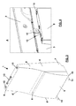
figures 1 and 2 show a part of a vehicle cab interior in which a removable backrest object of the invention is positioned with the smaller volume part tipped respectively downwards and upwards; -
figure 3 shows a perspective view of the removable backrest object of the invention; -
figure 4 shows a magnification of part A infigure 1 ; -
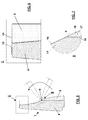
figure 5 shows a side section of the backrest; -
figures 6 and 7 show magnifications of parts B and C infigure 5 , respectively. - The same reference numbers in the figures identify the same elements.
- In the figures,
numeral 1 indicates a removable backrest object of the invention which may be positioned insidecab 2 of an industrial vehicle, e.g. in vertical position in aside compartment 3 of the cab. -
Removable backrest 1 consists of two parts: onelarger volume part 4 and onesmaller volume part 5. The two parts are connected together on anintermediate front line 6, andsmaller volume part 5 is hinged and may turn about thisline 6, so that when it is turned upwards it fills the retraction space of the shape oflarger volume part 4, so as to mate with this and form a parallelepiped. - Indeed,
larger volume part 4 presents an essentially parallelepiped-spaced lower part 7, and anupper part 8 whose thickness presents a concave curve trend starting from a maximum central thickness alongintermediate line 6, to a minimum thickness alongupper edge 9. - If the
intermediate front line 6 is median,smaller volume part 5 has a height equal to half the height oflarger volume part 4, and a thickness which presents a convex curved trend, complementary to the concave curved trend of the thickness ofupper part 8 oflarger volume part 4, starting from a nearly null thickness atintermediate line 6, to a maximum thickness onlower line 10, so that when it is turned upwards on hingingline 6, front face 5' of the smaller volume part mates with front face 8' of the larger volume part. - When
smaller volume part 5 is turned upwards, the removable backrest essentially assumes the shape of a regular parallelepiped, because the volume ofsmaller part 5 fills the vacuum of thelarger volume part 4, thus obtaining smaller front dimensions of the backrest. In this manner, if the backrest is positioned in a side recess 3 ofcab 2, it does not obstruct the tipping of a rear bed or of apart 11 thereof, arranged nearby. - On
edge 10 of lower side ofsmaller volume part 5 there arepresent extensions 14 of Velcro tape, e.g. male Velcro, which, when the smaller volume part is tipped upwards, are fastened on the equivalent parts of Velcrotape 15, e.g. female Velcro, present on the upper side of thelarger volume part 4, thus retaining the smaller volume part. - When
smaller volume part 5 is turned downwards, the removable backrest assumes a front essentially concave/convex-shaped front profile, thicker downwards and thinner upwards, for an optimal resting of the back of the person using it. -
Removable backrest 1 is fixed toinner side 3 ofcab 2 by means of a fastening system to ahook 12, for example a clothes hook, so that the backrest may be released and used also in other parts of the cab. For the purpose, ahandle 13 is fixed onto the upper part ofbackrest 1 and may be inserted inhook 12 as a clip - Advantageously, the two parts of
removable backrest 1 are provided withcover 16, e.g. fabric, and padding 17, e.g. foam. Hinges (not shown in the figures) are present on the two parts ofbackrest padding 17 may be inserted and removed. - Other possible construction variants of the described non-limitative example are possible, without because of this departing from the scope of protection of the present invention, comprising all the equivalent implementations for a person skilled in the art.
- From the above-mentioned description, a person skilled in the art will be capable of implementing the object of the invention without introducing further constructive details.
Claims (9)
- A removable backrest for vehicle cab interior, especially industrial or commercial vehicle,
characterised in that it essentially consists of two parts, one larger volume part (4) and one smaller volume part (5); said parts being connected together on an intermediate front line (6);
said smaller volume part (5) being hinged and able to turn about said intermediate front line (6), so that when it is turned upwards it fills the retraction space of the shape of said larger volume (4), so as to mate with the latter. - A removable backrest as in claim 1, characterised in that the larger volume part (4) presents an essentially parallelepiped-spaced lower part (7), and an upper part (8) whose thickness presents a concave curved course starting from a maximum central thickness along said intermediate line (6), to a minimum thickness along the upper edge (9).
- A removable backrest as in claim 2, characterised in that said smaller volume part (5) has a thickness which presents a convex curved trend, complementary to the concave curved trend of the thickness of said upper part (8) of the larger volume part (4), starting from a nearly null thickness at said intermediate line (6), to a maximum thickness on a lower line (10), so that when it turns upwards on said front intermediate line (6), the front face (5') of the smaller volume part mates with the front face (8') of the larger volume side.
- Removable backrest as in claim 3, characterised in that the edge (10) of the lower side of said smaller volume part (5) comprises extensions of Velcro tape (14), which, when said smaller volume part (5) is tipped upwards, is fastened on equivalent parts of Velcro tape (15), fastened on the upper side of said larger volume part (4).
- A removable backrest as in claim 1, characterised in that it assumes a front essentially convex/concave shaped front profile when said smaller volume part (5) is turned downwards, thicker downwards and thinner upwards, while it assumes an essentially parallelepiped shape when said smaller volume (5) is turned upwards.
- A removable backrest as per one or more of the preceding claims, characterised in that said two parts of the removable backrest are provided with cover (16) and padding (17).
- A removable backrest as in any of the preceding claims, characterised in that it comprises a handle (13) fixed onto the upper part of said backrest (1).
- A vehicle cab, especially industrial or commercial vehicle, characterised in that it comprises a compartment (3) for accommodating a removable backrest as in any of the preceding claims.
- A vehicle cab, as shown in claim 8, characterised in that it comprises in said compartment (3) a hook (12) adapted to fasten said handle (13) for stopping said removable backrest.
Applications Claiming Priority (1)
| Application Number | Priority Date | Filing Date | Title |
|---|---|---|---|
| ITMI20071367 ITMI20071367A1 (en) | 2007-07-09 | 2007-07-09 | REMOVABLE BACKREST FOR INTERNAL INDUSTRIAL OR COMMERCIAL VEHICLE CABIN, AND VEHICLE CABIN EQUIPPED WITH SUCH A REMOVABLE BACKREST |
Publications (3)
| Publication Number | Publication Date |
|---|---|
| EP2028038A2 true EP2028038A2 (en) | 2009-02-25 |
| EP2028038A3 EP2028038A3 (en) | 2010-03-03 |
| EP2028038B1 EP2028038B1 (en) | 2012-10-17 |
Family
ID=38529662
Family Applications (1)
| Application Number | Title | Priority Date | Filing Date |
|---|---|---|---|
| EP20080159914 Active EP2028038B1 (en) | 2007-07-09 | 2008-07-08 | Removable backrest for industrial or commercial vehicle cab interior, and vehicle cab provided with such removable backrest |
Country Status (7)
| Country | Link |
|---|---|
| EP (1) | EP2028038B1 (en) |
| CN (1) | CN101342878B (en) |
| AR (1) | AR070304A1 (en) |
| AU (1) | AU2008202905B2 (en) |
| BR (1) | BRPI0803852B1 (en) |
| ES (1) | ES2397223T3 (en) |
| IT (1) | ITMI20071367A1 (en) |
Cited By (2)
| Publication number | Priority date | Publication date | Assignee | Title |
|---|---|---|---|---|
| EP2025552A3 (en) * | 2007-07-10 | 2010-01-13 | Aguti Produktentwicklung & Design Gmbh | Seating assembly for an automobile, automobile interior device and automobile with a seating assembly |
| EP3345785B1 (en) | 2017-01-04 | 2019-09-04 | FASP automotive Seats S.R.L. | Convertible seat device for vehicles such as caravans or campers |
Family Cites Families (6)
| Publication number | Priority date | Publication date | Assignee | Title |
|---|---|---|---|---|
| GB2128473B (en) * | 1982-10-07 | 1986-05-14 | Motor Panels | Seats |
| DE3507529A1 (en) * | 1985-03-04 | 1986-09-04 | Iveco Magirus AG, 7900 Ulm | Driver's cab of a commercial vehicle with a bed behind the front seats |
| DE19518393C2 (en) * | 1995-05-19 | 1996-06-20 | Audi Ag | Motor vehicle |
| FR2761309B1 (en) * | 1997-03-28 | 1999-06-11 | Peugeot | BOOSTER SEAT FOR MOTOR VEHICLE |
| DE10216149C1 (en) * | 2002-04-12 | 2003-01-16 | Faurecia Autositze Gmbh & Co | Automobile passenger seat has two-part seat squab with hinged seat squab sections folding together for movement into vertical position facilitating seat removal |
| DE10340494B4 (en) * | 2003-09-03 | 2006-05-11 | Daimlerchrysler Ag | Passenger car with three rows of seats |
-
2007
- 2007-07-09 IT ITMI20071367 patent/ITMI20071367A1/en unknown
-
2008
- 2008-07-02 AU AU2008202905A patent/AU2008202905B2/en active Active
- 2008-07-04 AR ARP080102909 patent/AR070304A1/en unknown
- 2008-07-08 ES ES08159914T patent/ES2397223T3/en active Active
- 2008-07-08 EP EP20080159914 patent/EP2028038B1/en active Active
- 2008-07-09 BR BRPI0803852-0A patent/BRPI0803852B1/en active IP Right Grant
- 2008-07-09 CN CN2008101361834A patent/CN101342878B/en not_active Expired - Fee Related
Cited By (2)
| Publication number | Priority date | Publication date | Assignee | Title |
|---|---|---|---|---|
| EP2025552A3 (en) * | 2007-07-10 | 2010-01-13 | Aguti Produktentwicklung & Design Gmbh | Seating assembly for an automobile, automobile interior device and automobile with a seating assembly |
| EP3345785B1 (en) | 2017-01-04 | 2019-09-04 | FASP automotive Seats S.R.L. | Convertible seat device for vehicles such as caravans or campers |
Also Published As
| Publication number | Publication date |
|---|---|
| AU2008202905A1 (en) | 2009-01-29 |
| BRPI0803852B1 (en) | 2018-06-05 |
| AU2008202905B2 (en) | 2013-01-24 |
| EP2028038B1 (en) | 2012-10-17 |
| EP2028038A3 (en) | 2010-03-03 |
| BRPI0803852A2 (en) | 2009-06-16 |
| CN101342878B (en) | 2012-10-03 |
| CN101342878A (en) | 2009-01-14 |
| AR070304A1 (en) | 2010-03-31 |
| ES2397223T3 (en) | 2013-03-05 |
| ITMI20071367A1 (en) | 2009-01-10 |
Similar Documents
| Publication | Publication Date | Title |
|---|---|---|
| EP3083326B1 (en) | Vehicle seat | |
| US7527314B2 (en) | Vehicle gap guard | |
| JP2010064737A (en) | Harness storage system for child car seat | |
| US20050104422A1 (en) | Structure for securing cup support element in automotive seat | |
| US7841655B2 (en) | Motor vehicle seat, motor vehicle, and airbag module | |
| US20130249264A1 (en) | Vehicle seat | |
| EP2028038B1 (en) | Removable backrest for industrial or commercial vehicle cab interior, and vehicle cab provided with such removable backrest | |
| US6921129B2 (en) | Vehicle, especially a multipurpose vehicle | |
| US20060006684A1 (en) | Storage and tread unit | |
| CN211032286U (en) | Vehicle and sleeping berth device thereof | |
| JP2019182369A (en) | Vehicular seat | |
| JP6677104B2 (en) | Vehicle interior structure | |
| US20170349067A1 (en) | Seat System | |
| US12145483B2 (en) | Vehicle backrest structure | |
| US7163264B1 (en) | Head restraint with integrated tether anchor | |
| JP5661568B2 (en) | Car seat | |
| KR100916710B1 (en) | Car Cup Holder | |
| JP2010247822A (en) | Vehicle seat structure | |
| JP4446767B2 (en) | Vehicle tray arrangement structure | |
| JP4626421B2 (en) | Rear cargo compartment structure for vehicles | |
| JP2020203569A (en) | Vehicular seat | |
| US20070290530A1 (en) | Seat Recliner Bench for Motor Homes or the Like | |
| JP2023152048A (en) | vehicle seat | |
| KR19980017745U (en) | Rear seat retractable sleeping pillow | |
| KR20040003635A (en) | Fixing structure of tonneau cover for recreational vehicle |
Legal Events
| Date | Code | Title | Description |
|---|---|---|---|
| PUAI | Public reference made under article 153(3) epc to a published international application that has entered the european phase |
Free format text: ORIGINAL CODE: 0009012 |
|
| AK | Designated contracting states |
Kind code of ref document: A2 Designated state(s): AT BE BG CH CY CZ DE DK EE ES FI FR GB GR HR HU IE IS IT LI LT LU LV MC MT NL NO PL PT RO SE SI SK TR |
|
| AX | Request for extension of the european patent |
Extension state: AL BA MK RS |
|
| PUAL | Search report despatched |
Free format text: ORIGINAL CODE: 0009013 |
|
| AK | Designated contracting states |
Kind code of ref document: A3 Designated state(s): AT BE BG CH CY CZ DE DK EE ES FI FR GB GR HR HU IE IS IT LI LT LU LV MC MT NL NO PL PT RO SE SI SK TR |
|
| AX | Request for extension of the european patent |
Extension state: AL BA MK RS |
|
| 17P | Request for examination filed |
Effective date: 20100902 |
|
| 17Q | First examination report despatched |
Effective date: 20100928 |
|
| AKX | Designation fees paid |
Designated state(s): AT BE BG CH CY CZ DE DK EE ES FI FR GB GR HR HU IE IS IT LI LT LU LV MC MT NL NO PL PT RO SE SI SK TR |
|
| GRAJ | Information related to disapproval of communication of intention to grant by the applicant or resumption of examination proceedings by the epo deleted |
Free format text: ORIGINAL CODE: EPIDOSDIGR1 |
|
| GRAP | Despatch of communication of intention to grant a patent |
Free format text: ORIGINAL CODE: EPIDOSNIGR1 |
|
| GRAS | Grant fee paid |
Free format text: ORIGINAL CODE: EPIDOSNIGR3 |
|
| GRAA | (expected) grant |
Free format text: ORIGINAL CODE: 0009210 |
|
| AK | Designated contracting states |
Kind code of ref document: B1 Designated state(s): AT BE BG CH CY CZ DE DK EE ES FI FR GB GR HR HU IE IS IT LI LT LU LV MC MT NL NO PL PT RO SE SI SK TR |
|
| REG | Reference to a national code |
Ref country code: GB Ref legal event code: FG4D |
|
| REG | Reference to a national code |
Ref country code: CH Ref legal event code: EP |
|
| REG | Reference to a national code |
Ref country code: IE Ref legal event code: FG4D |
|
| REG | Reference to a national code |
Ref country code: AT Ref legal event code: REF Ref document number: 579744 Country of ref document: AT Kind code of ref document: T Effective date: 20121115 |
|
| REG | Reference to a national code |
Ref country code: DE Ref legal event code: R096 Ref document number: 602008019401 Country of ref document: DE Effective date: 20121213 |
|
| REG | Reference to a national code |
Ref country code: SE Ref legal event code: TRGR |
|
| REG | Reference to a national code |
Ref country code: NL Ref legal event code: T3 |
|
| REG | Reference to a national code |
Ref country code: ES Ref legal event code: FG2A Ref document number: 2397223 Country of ref document: ES Kind code of ref document: T3 Effective date: 20130305 |
|
| REG | Reference to a national code |
Ref country code: AT Ref legal event code: MK05 Ref document number: 579744 Country of ref document: AT Kind code of ref document: T Effective date: 20121017 |
|
| REG | Reference to a national code |
Ref country code: LT Ref legal event code: MG4D |
|
| PG25 | Lapsed in a contracting state [announced via postgrant information from national office to epo] |
Ref country code: NO Free format text: LAPSE BECAUSE OF FAILURE TO SUBMIT A TRANSLATION OF THE DESCRIPTION OR TO PAY THE FEE WITHIN THE PRESCRIBED TIME-LIMIT Effective date: 20130117 Ref country code: IS Free format text: LAPSE BECAUSE OF FAILURE TO SUBMIT A TRANSLATION OF THE DESCRIPTION OR TO PAY THE FEE WITHIN THE PRESCRIBED TIME-LIMIT Effective date: 20130217 Ref country code: FI Free format text: LAPSE BECAUSE OF FAILURE TO SUBMIT A TRANSLATION OF THE DESCRIPTION OR TO PAY THE FEE WITHIN THE PRESCRIBED TIME-LIMIT Effective date: 20121017 Ref country code: HR Free format text: LAPSE BECAUSE OF FAILURE TO SUBMIT A TRANSLATION OF THE DESCRIPTION OR TO PAY THE FEE WITHIN THE PRESCRIBED TIME-LIMIT Effective date: 20121017 Ref country code: LT Free format text: LAPSE BECAUSE OF FAILURE TO SUBMIT A TRANSLATION OF THE DESCRIPTION OR TO PAY THE FEE WITHIN THE PRESCRIBED TIME-LIMIT Effective date: 20121017 |
|
| PG25 | Lapsed in a contracting state [announced via postgrant information from national office to epo] |
Ref country code: BE Free format text: LAPSE BECAUSE OF FAILURE TO SUBMIT A TRANSLATION OF THE DESCRIPTION OR TO PAY THE FEE WITHIN THE PRESCRIBED TIME-LIMIT Effective date: 20121017 Ref country code: PL Free format text: LAPSE BECAUSE OF FAILURE TO SUBMIT A TRANSLATION OF THE DESCRIPTION OR TO PAY THE FEE WITHIN THE PRESCRIBED TIME-LIMIT Effective date: 20121017 Ref country code: PT Free format text: LAPSE BECAUSE OF FAILURE TO SUBMIT A TRANSLATION OF THE DESCRIPTION OR TO PAY THE FEE WITHIN THE PRESCRIBED TIME-LIMIT Effective date: 20130218 Ref country code: LV Free format text: LAPSE BECAUSE OF FAILURE TO SUBMIT A TRANSLATION OF THE DESCRIPTION OR TO PAY THE FEE WITHIN THE PRESCRIBED TIME-LIMIT Effective date: 20121017 Ref country code: CY Free format text: LAPSE BECAUSE OF FAILURE TO SUBMIT A TRANSLATION OF THE DESCRIPTION OR TO PAY THE FEE WITHIN THE PRESCRIBED TIME-LIMIT Effective date: 20121017 Ref country code: SI Free format text: LAPSE BECAUSE OF FAILURE TO SUBMIT A TRANSLATION OF THE DESCRIPTION OR TO PAY THE FEE WITHIN THE PRESCRIBED TIME-LIMIT Effective date: 20121017 |
|
| PG25 | Lapsed in a contracting state [announced via postgrant information from national office to epo] |
Ref country code: AT Free format text: LAPSE BECAUSE OF FAILURE TO SUBMIT A TRANSLATION OF THE DESCRIPTION OR TO PAY THE FEE WITHIN THE PRESCRIBED TIME-LIMIT Effective date: 20121017 |
|
| PG25 | Lapsed in a contracting state [announced via postgrant information from national office to epo] |
Ref country code: SK Free format text: LAPSE BECAUSE OF FAILURE TO SUBMIT A TRANSLATION OF THE DESCRIPTION OR TO PAY THE FEE WITHIN THE PRESCRIBED TIME-LIMIT Effective date: 20121017 Ref country code: DK Free format text: LAPSE BECAUSE OF FAILURE TO SUBMIT A TRANSLATION OF THE DESCRIPTION OR TO PAY THE FEE WITHIN THE PRESCRIBED TIME-LIMIT Effective date: 20121017 Ref country code: CZ Free format text: LAPSE BECAUSE OF FAILURE TO SUBMIT A TRANSLATION OF THE DESCRIPTION OR TO PAY THE FEE WITHIN THE PRESCRIBED TIME-LIMIT Effective date: 20121017 Ref country code: BG Free format text: LAPSE BECAUSE OF FAILURE TO SUBMIT A TRANSLATION OF THE DESCRIPTION OR TO PAY THE FEE WITHIN THE PRESCRIBED TIME-LIMIT Effective date: 20130117 Ref country code: EE Free format text: LAPSE BECAUSE OF FAILURE TO SUBMIT A TRANSLATION OF THE DESCRIPTION OR TO PAY THE FEE WITHIN THE PRESCRIBED TIME-LIMIT Effective date: 20121017 |
|
| PLBE | No opposition filed within time limit |
Free format text: ORIGINAL CODE: 0009261 |
|
| STAA | Information on the status of an ep patent application or granted ep patent |
Free format text: STATUS: NO OPPOSITION FILED WITHIN TIME LIMIT |
|
| PG25 | Lapsed in a contracting state [announced via postgrant information from national office to epo] |
Ref country code: RO Free format text: LAPSE BECAUSE OF FAILURE TO SUBMIT A TRANSLATION OF THE DESCRIPTION OR TO PAY THE FEE WITHIN THE PRESCRIBED TIME-LIMIT Effective date: 20121017 |
|
| 26N | No opposition filed |
Effective date: 20130718 |
|
| REG | Reference to a national code |
Ref country code: DE Ref legal event code: R097 Ref document number: 602008019401 Country of ref document: DE Effective date: 20130718 |
|
| PG25 | Lapsed in a contracting state [announced via postgrant information from national office to epo] |
Ref country code: MC Free format text: LAPSE BECAUSE OF FAILURE TO SUBMIT A TRANSLATION OF THE DESCRIPTION OR TO PAY THE FEE WITHIN THE PRESCRIBED TIME-LIMIT Effective date: 20121017 |
|
| REG | Reference to a national code |
Ref country code: CH Ref legal event code: PL |
|
| REG | Reference to a national code |
Ref country code: IE Ref legal event code: MM4A |
|
| PG25 | Lapsed in a contracting state [announced via postgrant information from national office to epo] |
Ref country code: CH Free format text: LAPSE BECAUSE OF NON-PAYMENT OF DUE FEES Effective date: 20130731 Ref country code: LI Free format text: LAPSE BECAUSE OF NON-PAYMENT OF DUE FEES Effective date: 20130731 |
|
| PG25 | Lapsed in a contracting state [announced via postgrant information from national office to epo] |
Ref country code: IE Free format text: LAPSE BECAUSE OF NON-PAYMENT OF DUE FEES Effective date: 20130708 |
|
| REG | Reference to a national code |
Ref country code: FR Ref legal event code: PLFP Year of fee payment: 8 |
|
| PG25 | Lapsed in a contracting state [announced via postgrant information from national office to epo] |
Ref country code: MT Free format text: LAPSE BECAUSE OF FAILURE TO SUBMIT A TRANSLATION OF THE DESCRIPTION OR TO PAY THE FEE WITHIN THE PRESCRIBED TIME-LIMIT Effective date: 20121017 Ref country code: TR Free format text: LAPSE BECAUSE OF FAILURE TO SUBMIT A TRANSLATION OF THE DESCRIPTION OR TO PAY THE FEE WITHIN THE PRESCRIBED TIME-LIMIT Effective date: 20121017 |
|
| PG25 | Lapsed in a contracting state [announced via postgrant information from national office to epo] |
Ref country code: HU Free format text: LAPSE BECAUSE OF FAILURE TO SUBMIT A TRANSLATION OF THE DESCRIPTION OR TO PAY THE FEE WITHIN THE PRESCRIBED TIME-LIMIT; INVALID AB INITIO Effective date: 20080708 Ref country code: LU Free format text: LAPSE BECAUSE OF NON-PAYMENT OF DUE FEES Effective date: 20130708 |
|
| PG25 | Lapsed in a contracting state [announced via postgrant information from national office to epo] |
Ref country code: GR Free format text: LAPSE BECAUSE OF NON-PAYMENT OF DUE FEES Effective date: 20121017 |
|
| REG | Reference to a national code |
Ref country code: FR Ref legal event code: PLFP Year of fee payment: 9 |
|
| REG | Reference to a national code |
Ref country code: FR Ref legal event code: PLFP Year of fee payment: 10 |
|
| REG | Reference to a national code |
Ref country code: FR Ref legal event code: PLFP Year of fee payment: 11 |
|
| PGFP | Annual fee paid to national office [announced via postgrant information from national office to epo] |
Ref country code: NL Payment date: 20190729 Year of fee payment: 12 |
|
| PGFP | Annual fee paid to national office [announced via postgrant information from national office to epo] |
Ref country code: SE Payment date: 20190725 Year of fee payment: 12 |
|
| PGFP | Annual fee paid to national office [announced via postgrant information from national office to epo] |
Ref country code: GB Payment date: 20190729 Year of fee payment: 12 |
|
| REG | Reference to a national code |
Ref country code: SE Ref legal event code: EUG |
|
| REG | Reference to a national code |
Ref country code: NL Ref legal event code: MM Effective date: 20200801 |
|
| GBPC | Gb: european patent ceased through non-payment of renewal fee |
Effective date: 20200708 |
|
| PG25 | Lapsed in a contracting state [announced via postgrant information from national office to epo] |
Ref country code: GB Free format text: LAPSE BECAUSE OF NON-PAYMENT OF DUE FEES Effective date: 20200708 Ref country code: NL Free format text: LAPSE BECAUSE OF NON-PAYMENT OF DUE FEES Effective date: 20200801 |
|
| PG25 | Lapsed in a contracting state [announced via postgrant information from national office to epo] |
Ref country code: SE Free format text: LAPSE BECAUSE OF NON-PAYMENT OF DUE FEES Effective date: 20200709 |
|
| P01 | Opt-out of the competence of the unified patent court (upc) registered |
Effective date: 20230523 |
|
| PGFP | Annual fee paid to national office [announced via postgrant information from national office to epo] |
Ref country code: ES Payment date: 20250812 Year of fee payment: 18 |
|
| PGFP | Annual fee paid to national office [announced via postgrant information from national office to epo] |
Ref country code: DE Payment date: 20250728 Year of fee payment: 18 |
|
| PGFP | Annual fee paid to national office [announced via postgrant information from national office to epo] |
Ref country code: IT Payment date: 20250701 Year of fee payment: 18 |
|
| PGFP | Annual fee paid to national office [announced via postgrant information from national office to epo] |
Ref country code: FR Payment date: 20250725 Year of fee payment: 18 |