EP2027008B1 - Bearbeitungsstation, insbesondere fügestation - Google Patents
Bearbeitungsstation, insbesondere fügestation Download PDFInfo
- Publication number
- EP2027008B1 EP2027008B1 EP07725909.1A EP07725909A EP2027008B1 EP 2027008 B1 EP2027008 B1 EP 2027008B1 EP 07725909 A EP07725909 A EP 07725909A EP 2027008 B1 EP2027008 B1 EP 2027008B1
- Authority
- EP
- European Patent Office
- Prior art keywords
- frame
- station according
- machining station
- clamping
- clamping frames
- Prior art date
- Legal status (The legal status is an assumption and is not a legal conclusion. Google has not performed a legal analysis and makes no representation as to the accuracy of the status listed.)
- Revoked
Links
Images




Classifications
-
- B—PERFORMING OPERATIONS; TRANSPORTING
- B23—MACHINE TOOLS; METAL-WORKING NOT OTHERWISE PROVIDED FOR
- B23P—METAL-WORKING NOT OTHERWISE PROVIDED FOR; COMBINED OPERATIONS; UNIVERSAL MACHINE TOOLS
- B23P21/00—Machines for assembling a multiplicity of different parts to compose units, with or without preceding or subsequent working of such parts, e.g. with program control
- B23P21/002—Machines for assembling a multiplicity of different parts to compose units, with or without preceding or subsequent working of such parts, e.g. with program control the units stationary whilst being composed
-
- B—PERFORMING OPERATIONS; TRANSPORTING
- B23—MACHINE TOOLS; METAL-WORKING NOT OTHERWISE PROVIDED FOR
- B23P—METAL-WORKING NOT OTHERWISE PROVIDED FOR; COMBINED OPERATIONS; UNIVERSAL MACHINE TOOLS
- B23P2700/00—Indexing scheme relating to the articles being treated, e.g. manufactured, repaired, assembled, connected or other operations covered in the subgroups
- B23P2700/50—Other automobile vehicle parts, i.e. manufactured in assembly lines
Definitions
- the invention relates to a processing station, in particular a joining station, with the features in the preamble of the main claim.
- Such a joining station for body parts is from the WO 01/94191 A1 known.
- One or more industrial robots are arranged on a common travel axis on both sides of the transfer line between a frame magazine and a frame with a workstation. They have a dual function as a combined frame change and processing device. They cause the replacement of the clamping frame on the frame and add the workpieces after a tool change.
- the clamping frames are height-adjustable mounted on the frame and aligned transversely to the transfer line.
- the EP 1 518 784 A2 shows a different joining station for body parts with a bottom circumferential frame with multiple docking stations, each for bottom-receiving a single standing and angled tool arm with multiple clamping tools are used, which is supplied by the docking with resources.
- the tool arms with their docking station are arranged at a distance from each other on the floor frame, whereby free spaces for the penetration of welding robots are formed.
- the robots have a dual function as a combined tool arm changing and machining device.
- the EP 1 473 214 A1 discloses different joining stations for side walls and roof parts of vehicle bodies.
- multi-part side frames are movable on carriages transversely to the transfer line, passing by a welding robot.
- portals are arranged on both sides of the transfer line, on the upper side of which robots place tensioning beams with an alignment transversely to the transfer line.
- the WO 98/45085 A1 discloses a joining station with a gantry-type station frame to which left and right side gantries are fed and suspended by stationary feed robots.
- the body is held on a workpiece holder with sockets or other positioning.
- the clamping tools can be replaced individually at the workplace by a robot.
- Another workstation is out of the EP 0 583 282 B1 known. It has a portal-like frame with one or both sides of a transfer line arranged jobs and one or more arranged next to the work frame magazines, which are designed as a rotatable drum magazine.
- a frame changing device is provided, which consists of a movable along the transfer line hanging train and a transversely movable to the transfer line carriage with a frame for clamping frame recording.
- the tenter frames are transported from the frame magazine to the frame by the hanging hoist, transferred there and then transported on to the frame, where they are fixed with a stakeout.
- processing robots in particular joining robots or welding robots are arranged behind the frame.
- a machining station in which several robots perform tentering frames to the work site and join together to form a cubic tenter housing and interconnect.
- the clamping frame housing encloses the body on several sides.
- the clamping frames are based on each other, the transport pallet, the transport body acts as the bottom part of the tenter frame.
- the invention solves this problem with the features in the main claim.
- the claimed clamping frame and handling technology and the processing station have the advantage of high flexibility. It can be used a variety of different clamping frames, which is adapted to different workpiece types, especially body and component types. Another advantage lies in the short frame change times. The available cycle time can be better exploited while minimizing set-up times. This leads to better station utilization and higher efficiency.
- the processing station also has only a small footprint and in particular a small station width, which also has an effect on an increase in cost-effectiveness.
- the implementation of the frame change with one or more multi-axis manipulators with several intersecting and e.g. Orthogonal axes, preferably with articulated arm robots with at least six axes, allows a simplification and reduction of the frame magazines and the storage technology.
- the preferably slender and elongated clamping frames can be rotated by the manipulators and stored in an upright position in the frame magazine by means of suitable frame holder. This reduces the space requirement.
- the clamping frames can be handled in a small space and in any straight and / or curved spatial trajectories.
- a multi-axis feed movement such as a feed and lifting movement or hooking be performed.
- the manipulator or robot can stand laterally offset next to the workstation for the frame change.
- the slim tenter shape also offers the advantage that several frames can be positioned on the frame as needed.
- the tenter frame functions can be shared here, e.g. in a lower sill area in which the tensioner are arranged on tenter or stationary. In the upper body area, the clamping function can be fulfilled by a clamping frame there.
- the manipulators or handling robots preferably take over the complete guidance and movement as well as the delivery of the clamping frames and for this purpose have several axes of movement. This allows a simplification of the frame magazines, which can be dispensed with axes of movement.
- the frame magazines can thereby be designed to be stationary and executed in a stand construction. This significantly reduces the space requirements and the construction and cost. In addition, such frame magazines can be more easily adapted to the respective requirements and capacities.
- the positioning device for positioning and fixation the tenter in the working position in the frame is simplified, refined and improved, the feed kinematics is easier and cheaper.
- the tenter can be moved by the manipulator on any path, and it can also be tilted or tilted. This allows a frame delivery with already positioned body. Due to the frame kinematics, additional movement axes for the clamps on the clamping frame can be dispensed with.
- Further advantages of the manipulator guide of the clamping frame is an improvement of the power supply of the clamping frame and a reduced space requirement in the field of work.
- the manipulator can remain connected during the machining process with the clamping frame, which is still given by the small interference contour good accessibility of the workpiece or the body through the arranged behind the manipulator processing device.
- the tensioning frame technique also allows a simplification of the frame of the processing station and a reduction of its interference contours in conjunction with a better accessibility of the workpiece or the body.
- the frame can be formed in the simple case of upright and free-standing columns. A portal shape is not required. As a result, the accessibility is significantly improved in the upper body area.
- the columns may also be adjustably mounted on a support member and can be adapted to different space and tenter frame requirements.
- the claimed processing station can be modular in their essential components, whereby a modular system can be formed.
- the frame magazines can have a simple and modular steel construction and arbitrarily linear or in an arc around the
- Motion axis of the frame changing device may be arranged. This makes it possible to integrate new types of clamping frames at any time. The maintenance and servicing of the clamping frame is simplified and improved.
- the modular concept or modular principle increases profitability and simplifies the planning and design of processing stations. In addition, the flexibility is increased because the processing station can be adapted to a change in workpiece types or body types with a relatively low cost.
- the frame changing device formed by one or more manipulators with the possibly existing additional movement axis offers a variety of possibilities for flexibility.
- the invention relates to a clamping frame technique and a processing station (1) equipped therewith.
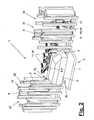
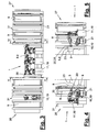
- FIG. 1 to 5 a processing station (1) is shown in different views. In this case, only one station half is shown for reasons of clarity.
- the processing station (1) is provided for any machining processes on any workpieces (3) which are fed, for example, along a transfer line (2) extending through the station with suitable conveyors.
- the workpieces (3) are vehicle bodies, in particular body shells.
- Joining operations on the body (3) are carried out in the processing station (1), wherein the body (3) or one or more components (4) of the body (3), eg a side wall, by means of one or more clamping frames (8, 9), be stretched and connected at the workstation (35). Possibly.
- Components (4) can also be supplied with the or the clamping frame (8,9) to the workstation (35).
- the joining processes for connecting the components or body parts can be of any type, eg welding, gluing, soldering or the like ..
- the bodywork (3) is accurately positioned in the processing station (1) at the workstation (35) in a suitable manner so that there is an exact alignment between the bodywork (3) and the tentering frame (s) (8, 9).
- the components of the processing station (1) shown in the drawings can be arranged only on one side or alternatively on both sides of the transfer line (2) for a one- or two-sided processing of the vehicle body (3).
- the processing station (1) has a frame (5) on which the clamping frames (8, 9) can be exactly positioned and fixed at the workstation (35) by means of a positioning device (12).
- the processing station (1) is e.g. designed as a joining station, in particular as a so-called geostation, in which the body parts are aligned exactly to each other and stretched for the machining process.
- the frame (5) can be formed in any desired manner. In the shown and preferred embodiment, it consists of two or more free and upright support columns (6) on which the clamping frames (8,9) are positioned and fixed. In a bilateral station training four distributed in the rectangle support columns (6) are present. The support columns (6) are supported on the bottom side in a suitable manner for receiving the clamping and positioning forces.
- the support can be rigid or adjustable.
- the support columns (6) can be anchored to the station floor or hall floor. Alternatively, they may be arranged and fixed to a support element (7), eg a base plate.
- the column arrangement can be adjustable according to one or more directions, for example in the x and / or y axis, wherein, for example, an adjustment grid is present. This can in particular the distance in the x direction between the Support columns (6) to be adapted to different clamping frame sizes.
- the processing station (1) has, in addition to the job (s) (35) one or more magazines (26,27) for one or more clamping frames (8,9). Furthermore, a frame changing device (10) is provided with which the clamping frames (8,9) can be exchanged and transported from the frame magazines (26,27) to the workstation (35) and back.
- the frame changing device (10) has one or more multi-axis manipulators (19), which can handle the various clamping frames (8,9) and multi-axis lead.
- the manipulators (19) can be designed in any suitable manner. They preferably have several, e.g. five or more intersecting axes of motion, e.g. orthogonal to each other. These can be rotational and / or translatory axes. In the exemplary embodiment shown, they are designed as multiaxial, in particular six-axis articulated-arm robots or so-called handling robots. They include an e. G. vertical axis on a frame rotatable carousel, a thereto about. a horizontal axis pivoting rocker and one at the swing end in turn e.g. horizontally pivotally mounted boom on.
- the manipulator (19) has a multi-axis robot hand (20) with e.g. two or three axes, e.g. is arranged at the boom end.
- the robot hand (20) can carry a suitable change-coupling which can be releasably engaged with a docking device (25) on the clamping frame (8,9).
- a docking device (25) on the clamping frame (8,9).
- About the removable coupling and the docking device (25) can be supplied by means of suitable lines and coupling elements operating equipment, such as compressed air, power, coolant or the like.
- the power and signal supply of the clamping frame (8,9) can also be created in other ways, for example via suitable couplings and connections on the frame (5), which are automatically closed in a frame positioning and reopened when changing the frame.
- the manipulator or manipulators (19) have one or more additional axes of movement (21).
- This can e.g. a straight or curved driving axis or seventh axis of the robot (19), which is possibly aligned parallel to the transfer line (2) and is arranged on one or both sides of the transfer line (2).
- the manipulators (19) for the tensioning frame transport between the workstation (35) and the frame or the magazine (26,27) can move back and forth.
- the additional movement axis (21) can be formed by a conveyor or another transport device as an alternative to the embodiment shown. It does not have to be linear.
- an additional axis e.g. serve a swinging system.
- the manipulators (19) according to the invention in the work area of the station (1) between the work (35) and the frame (5) and a processing device (11) are arranged.
- the additional movement axis (21) also extends in an area between the frame (5) and the processing device (11).
- the processing device (11) can have one or more multi-axis manipulators (18) with processing tools. These can be eg joining robots, in particular welding robots. These robots may also be designed as six-axis articulated arm robots and possibly be arranged on pedestals or with additional axes. The range of the joining robots (18) and their mobility is so great that they can reach the body (3) at the workstation (35) and can thereby move past the handling robot (19) possibly at the workstation (35). In idle position, the joining robots (18) release the travel path and other movement space for the handling robot (19) during the frame change.
- multi-axis manipulators (18) with processing tools can be eg joining robots, in particular welding robots. These robots may also be designed as six-axis articulated arm robots and possibly be arranged on pedestals or with additional axes. The range of the joining robots (18) and their mobility is so great that they can reach the body (3) at the workstation (35) and can thereby move past the handling robot (19) possibly at the workstation (35). In
- the handling robot (19) can be released from the clamping frame or frame (8, 9) and removed from the workstation (35). Alternatively, it can remain connected to the clamping frame or frames (8, 9) and remain in place (35).
- FIGS. 11 to 16 show different variants of clamping frames (8,9) in different views and positions on the frame (5).
- the clamping frames (8,9) are equipped with one or more tensioners (23), with which the body parts can be tensioned.
- the movable tensioner elements can be driven in any suitable manner.
- the power supply can in the aforementioned manner on the docking device (25), which is designed for example as energy and change coupling or otherwise via suitable connections in the frame (5).
- the tensioner (23) can in particular self-locking drives, eg toggle lever drives, which hold the movable tensioner parts in the clamping position.
- the self-locking allows after the clamping frame positioning disconnecting the power supply and allows a release of the handling robot (19) from the clamping frame (8.9).
- the handling robot (19) can then leave the workstation (35) and completely clear the access for the processing device (11).
- the clamping frames (8,9) may have an elongated and narrow or slender shape. You can eg in the variants of FIG. 11 . 12 and 14 to 16 a beam-like carrier (22), for example, has a substantially I-shape.
- the clamping frames (8, 9) are preferably positioned on the frame (5) with a substantially horizontal orientation, with the carrier (22) extending horizontally and parallel to the transfer line (2). Arranged transversely to the support end and upright in the frame position support arms, which carry at the end centering elements (17) for the positioning device explained below (12).
- the carrier (22) is formed, for example, as a torsion and bending resistant and box-shaped hollow body.
- the tensioner (23) may be arranged individually or in groups in any orientation and position on the carrier (22) rigid or movable with an additional axis. Preferably, they are arranged on the carrier delivery side.
- FIG. 14 clarified in the page presentation that the tensioner (23) in their distribution and arrangement can form an antler-like tensioner contour.
- FIG. 15 shows in the folded end view of the tensioner alignment to the body. In FIGS. 1 to 13 the tensioners (23) are shown schematically as an outline of the entire tensioner group.
- FIG. 11 is a single slender clamping frame (8) with its support (22) horizontally and horizontally disposed in the upper region of the frame (5) and the stubby support columns (6). Its tensioners (23) are used to tension the upper body areas. Below the clamping frame (8) on the frame (5), in particular on the bottom plate (7) further tensioner (24) may be arranged, which for the lower body portion or Threshold area are provided and, for example, tension the bottom group of the body (3) with the side wall.
- the tensioner (24) can be arranged rigidly or one or more than twelve axes adjustable.
- a fine positioning in adaptation to changing vehicle types can be achieved.
- the tensioning configuration shown has advantages for body types, e.g. in Boden phenomenon- or Schweller Scheme have substantially the same shape and differ from type to type in the upper body area. Such type differences exist e.g. in 2- or 4-door body variants or hatchback and notchback variants or the like. The same vehicle series. In these cases, when changing the body type only the clamping frame (8) to replace.
- the clamping geometry of the lower further tensioner (24) can remain the same or adapted in the aforementioned manner, in particular delivered.
- FIG. 12 shows a modification of FIG. 11 in which two slender clamping frames (8, 9) are positioned one above the other in the frame (5).
- the lower clamping frame (9) replaces the other tensioner (24) and can be exchanged together or independently of the upper clamping frame (8) in a type change.
- more than two clamping frames (8,9) can be arranged one above the other.
- a plurality of clamping frames (8, 9) can alternatively or additionally be juxtaposed in the frame (5).
- FIG. 13 shows a variant of the clamping frame (8,9) in a wider version, which is suitable for small vehicles, for example.
- a plurality of horizontally oriented carrier or frame parts are provided with end frame connections.
- a rectangular in the side view encircling frame can be formed.
- the docking device (25) is also arranged here at a suitable location and preferably in the center and at the rear of the frame.
- the larger frame (8,9) of FIG. 13 For example, it is able to tension the complete side wall (4) of the body (3).
- Such a clamping frame (8,9) is also particularly suitable for a component feed during frame delivery or during frame change.
- the positioning device (12) serves for the exact positioning of the clamping frames (8, 9) on the frame (5). It offers one or more centerings (13,14,15). In addition, a fixing device (not shown) is provided, with which the assumed frame position can be secured. This can be, for example, a controllable tension lever or the like. As FIGS. 11 to 13 illustrate for example, four centerings (13,14,15) are available for each clamping frame (8.9).
- the two upper y-centerings (13) act in the direction of the Y-axis and transversely to the transfer line (2).
- the one lower centering is designed as x, y, z centering with effect in all three spatial axes X, Y, Z.
- On the opposite side on the other support column (6) an x, y-centering (14) is arranged on the frame bottom. About the centerings (13,14,15) positioning in all six translational and rotational axes is possible.
- each cooperating centering elements (16) on the frame and in particular on the support columns (6) and centering elements (17) on the clamping frame (8,9) are present.
- FIGS. 8 and 9 show as enlarged views too FIG. 7 Detailed representations of the centering element (16,17) and the y-centerings (13).
- the frame magazines (26,27) can be arranged on both sides of the workstation (35) and formed identical or different. Alternatively, they can only be located on one station side. In a double-sided station training four or less frame magazines (26,27) may be present.
- the frame magazines (26,27) each have a plurality of frame holder (31), which are preferably designed for an upright clamping frame position and storage.
- the frame holders (31) are arranged stationary in the embodiments shown and each consist of two vertical support columns (32) with support elements (33) for the clamping frame (8,9).
- the elongated clamping frames (8,9) are rotated by the handling robot (19) from its horizontal working position after removal from the frame (5) by approximately 90 ° and transferred to the frame holder (31) with a substantially vertical orientation, where they can be kept standing or hanging.
- the support elements (33) on the support columns (32) can be adapted to the centering elements (17) of the clamping frame (8,9) or other clamping frame parts and ensure an exact clamping frame positioning in the frame holder (31).
- Figure 1 to 5 illustrate a magazine training, in which a part of the frame holder (31) are arranged in one or more rows on one or both sides of the additional movement axis (21) in an axis-parallel position.
- Adjacent frame holders (31) may have common support columns (32).
- the magazines (26,27) can be formed by the space-saving design a variety of storage spaces for the different clamping frames (8.9).
- the magazines (26, 27) can also be subdivided into magazine areas (28, 29, 30) in which similar clamping frames (8, 9) are arranged one below the other.
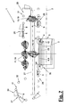
- FIG. 7 shows an example of such an arrangement.
- clamping frames (8) are housed, for example, according to FIG. 12 intended for the upper body area.
- These narrow clamping frames (8) are accommodated in row-shaped frame holders (31).
- the tenter frames (8) differ from one another with regard to the body type and the purpose of the tensioner geometry provided for this purpose.
- the other magazine area (29) which consists of a series arrangement of frame holders (31) on the other side of the additional movement axis (21), the other narrow clamping frames (9) are received, according to FIG. 12 intended for the sill area.
- the third magazine area (30) which shows, for example, an arcuate arrangement of frame holders (31), larger clamping frames (8) are accommodated, for example the variant of FIG FIG. 13 correspond.
Landscapes
- Engineering & Computer Science (AREA)
- Mechanical Engineering (AREA)
- Specific Conveyance Elements (AREA)
- Automatic Assembly (AREA)
- Treatment Of Fiber Materials (AREA)
Description
- Die Erfindung betrifft eine Bearbeitungsstation, insbesondere eine Fügestation, mit den Merkmalen im Oberbegriff des Hauptanspruchs.
- Eine solche Fügestation für Karosserieteile ist aus der
WO 01/94191 A1 - Die
EP 1 518 784 A2 zeigt eine andere Fügestation für Karosserieteile mit einem bodenseitigen umlaufenden Rahmen mit mehreren Dockingstationen, die jeweils zur bodenseitigen Aufnahme eines einzelnen stehenden und abgewinkelten Werkzeugarms mit mehreren Spannwerkzeugen dienen, der von der Dockingstation mit Betriebsmitteln versorgt wird. Die Werkzeugarme mit ihrer Dockingstation sind an dem Bodenrahmen mit Abstand voneinander angeordnet, wodurch Freiräume für den Durchgriff von Schweißrobotern gebildet werden. Die Roboter haben eine Doppelfunktion als kombinierte Werkzeugarmwechsel- und Bearbeitungseinrichtung. - Die
EP 1 473 214 A1 offenbart unterschiedliche Fügestationen für Seitenwände und Dachteile von Fahrzeugkarosserien. Zum Fügen der Seitenwände sind mehrteilige Seitenrahmen auf Schlitten quer zur Transferlinie verfahrbar, wobei sie an einem Schweißroboter vorbeifahren. Zum Fügen der Dachteile sind beidseits der Transferlinie Portale angeordnet, auf deren Oberseite Roboter Spannbalken mit einer Ausrichtung quer zur Transferlinie auflegen. - Die
WO 98/45085 A1 - Bei der
EP 1 277 540 A2 ist zu beiden Seiten der Fahrzeugkarosserie jeweils ein modularer Seitenspannrahmen angeordnet, dessen Spannwerkzeuge an der Arbeitsstelle von einem Roboter einzeln ausgewechselt werden können. - Eine andere Bearbeitungsstation ist aus der
EP 0 583 282 B1 bekannt. Sie weist ein portalartiges Gestell mit ein oder beidseits einer Transferlinie angeordneten Arbeitsstellen und ein oder mehrere neben der Arbeitsstelle angeordnete Rahmenmagazine auf, die als drehbares Trommelmagazin ausgebildet sind. Für den Spannrahmentransport zwischen den Rahmenmagazinen und der Arbeitsstelle am Gestell ist eine Rahmenwechseleinrichtung vorgesehen, die aus einem längs der Transferlinie verfahrbaren Hängezug und einem quer zur Transferlinie verfahrbaren Schlitten mit einem Gestell zur Spannrahmenaufnahme besteht. Die Spannrahmen werden vom Rahmenmagazin mit dem Hängezug an das Gestell transportiert, dort übergeben und dann weiter zum Gestell transportiert, wo sie mit einer Absteckung fixiert werden. Auf dem Schlitten sind hinter dem Gestell mehrere Bearbeitungsroboter, insbesondere Fügeroboter oder Schweißroboter, angeordnet. - Aus der
EP 0 760 770 B1 ist eine Bearbeitungsstation bekannt, in der mehrere Roboter Spannrahmen an die Arbeitsstelle zuführen und zu einem kubischen Spannrahmengehäuse zusammenstecken und untereinander verbinden. Das Spannrahmengehäuse umschließt an mehreren Seiten die Karosserie. Im Spannrahmengehäuse stützen sich die Spannrahmen gegenseitig ab, wobei die Transportpalette die Transportkarosserie als Bodenteil des Spannrahmengehäuses fungiert. - Es ist Aufgabe der vorliegenden Erfindung, eine weiterentwickelte Spannrahmentechnik aufzuzeigen.
- Die Erfindung löst diese Aufgabe mit den Merkmalen im Hauptanspruch.
Die beanspruchte Spannrahmen- und Handhabungstechnik und die Bearbeitungsstation haben den Vorteil einer hohen Flexibilität. Es kann eine Vielzahl unterschiedlicher Spannrahmen eingesetzt werden, die an verschiedene Werkstücktypen, insbesondere Karosserie- und Bauteiltypen, angepasst ist. Ein weiterer Vorteil liegt in den kurzen Rahmenwechselzeiten. Die verfügbare Taktzeit lässt sich dadurch unter Minimierung der Rüstzeiten besser ausnutzen. Dies führt zu einer besseren Stationsauslastung und einer höheren Wirtschaftlichkeit. Die Bearbeitungsstation hat außerdem nur einen geringen Platzbedarf und insbesondere eine geringe Stationsbreite, was sich ebenfalls in einer Steigerung der Wirtschaftlichkeit auswirkt. - Die Durchführung des Rahmenwechsels mit ein oder mehreren mehrachsigen Manipulatoren mit mehreren sich kreuzenden und z.B. orthogonalen Achsen, vorzugsweise mit Gelenkarmrobotern mit mindestens sechs Achsen, erlaubt eine Vereinfachung und Verkleinerung der Rahmenmagazine und der Speichertechnik. Die vorzugsweise schlanken und länglichen Spannrahmen können von den Manipulatoren gedreht und in einer aufrechten Position im Rahmenmagazin mittels geeigneter Rahmenhalter gespeichert werden. Dies verringert den Platzbedarf.
- Für das Handling eines Spannrahmens genügt ein einzelner Manipulator. Durch die Mehrachsigkeit und den bevorzugten Einsatz einer mehrachsigen Manipulator- oder Roboterhand können die Spannrahmen auf engem Raum und in beliebigen geraden und/oder gekrümmten räumliche Bewegungsbahnen gehandhabt werden. Insbesondere kann bei der Zustellung des Spannrahmens an das Gestell und die dortige des Spannrahmens an das Gestell und die dortige Positioniereinrichtung eine mehrachsige Zustellbewegung, z.B. eine Zuführ- und Hebebewegung oder Einhängbewegung ausgeführt werden. Der Manipulator oder Roboter kann für den Rahmenwechsel seitlich versetzt neben der Arbeitsstelle stehen.
- Über eine zusätzliche Bewegungsachse des oder der Manipulatoren kann außerdem deren Bewegungsbereich für den Spannrahmenwechsel erweitert und bei Bedarf die Magazingröße gesteigert werden. Durch die Speichertechnik und die Magazingestaltung können außerdem die Transportwege und die Rahmenwechselzeiten verkürzt werden. Die schlanke Spannrahmenform bietet ferner den Vorteil, dass am Gestell mehrere Spannrahmen bei Bedarf positioniert werden können. Die Spannrahmenfunktionen können hierbei geteilt werden, z.B. in einen unteren Schwellerbereich, in dem die Spanner an Spannrahmen oder stationär angeordnet sind. Im oberen Karosseriebereich kann die Spannfunktion durch einen dortigen Spannrahmen erfüllt werden.
- Die Manipulatoren oder Handlingroboter übernehmen vorzugsweise die komplette Führung und Bewegung sowie Zustellung der Spannrahmen und haben hierfür mehrere Bewegungsachsen. Dies ermöglicht eine Vereinfachung der Rahmenmagazine, bei denen auf Bewegungsachsen verzichtet werden kann. Die Rahmenmagazine können hierdurch stationär ausgebildet und in Ständerbauweise ausgeführt sein. Dies verringert erheblich den Platzbedarf und den Bau- sowie Kostenaufwand. Außerdem lassen sich derartige Rahmenmagazine leichter an die jeweiligen Erfordernisse und Kapazitäten anpassen.
- Die Handhabung der Spannrahmen durch ein oder mehrere Manipulatoren bietet weitere Vorteile. Einerseits kann die Positioniereinrichtung zur Positionierung und Fixierung der Spannrahmen in der Arbeitsstellung im Gestell vereinfacht, präzisiert und verbessert werden, wobei die Zuführkinematik einfacher und günstiger wird. Bei der Zuführung zum Gestell kann der Spannrahmen vom Manipulator auf einer beliebigen Bahn bewegt werden, wobei er auch gekippt oder geschwenkt werden kann. Dies ermöglicht eine Rahmenzustellung bei bereits positionierter Karosserie. Durch die Rahmenkinematik kann außerdem auf zusätzliche Bewegungsachsen für die Spanner am Spannrahmen verzichtet werden. Weitere Vorteile der Manipulatorführung der Spannrahmen ist eine Verbesserung der Energieversorgung der Spannrahmen und ein verringerter Platzbedarf im Bereich der Arbeitsstelle. Der Manipulator kann während des Bearbeitungsprozesses mit dem Spannrahmen verbunden bleiben, wobei durch die kleine Störkontur trotzdem eine gute Erreichbarkeit des Werkstücks bzw. der Karosserie durch die hinter dem Manipulator angeordnete Bearbeitungseinrichtung gegeben ist.
- Die Spannrahmentechnik ermöglicht ferner eine Vereinfachung des Gestells der Bearbeitungsstation und eine Verringerung seiner Störkonturen in Verbindung mit einer besseren Erreichbarkeit des Werkstücks bzw. der Karosserie. Das Gestell kann im einfachen Fall von aufrecht und frei stehenden Säulen gebildet werden. Eine Portalform ist nicht erforderlich. Hierdurch ist im oberen Karosseriebereich die Zugänglichkeit wesentlich verbessert. Die Säulen können außerdem an einem Tragelement verstellbar gelagert sein und sich an unterschiedliche Platz- und Spannrahmenerfordernisse anpassen lassen.
- Die beanspruchte Bearbeitungsstation kann in ihren wesentlichen Komponenten modular aufgebaut sein, wobei auch ein Baukastensystem gebildet werden kann. Die Rahmenmagazine können ein einfachen und modularen Stahlbau haben und beliebig linear oder im Bogen um die
- Bewegungsachse der Rahmenwechseleinrichtung angeordnet sein. Hierdurch ist die Integration neuer Spannrahmentypen jederzeit möglich. Auch die Wartung und Instandhaltung der Spannrahmen wird vereinfacht und verbessert. Das modulare Konzept oder Baukastenprinzip steigert die Wirtschaftlichkeit und vereinfacht die Planung und Auslegung von Bearbeitungsstationen. Zudem wird die Flexibilität gesteigert, weil sich die Bearbeitungsstation einer Änderung der Werkstücktypen oder Karosserietypen mit einem vergleichsweise geringem Aufwand anpassen lässt. Die von ein oder mehreren Manipulatoren gebildete Rahmenwechseleinrichtung mit der ggf. vorhandenen zusätzlichen Bewegungsachse bietet für die Flexibilisierung mannigfaltige Möglichkeiten.
- In den Unteransprüchen sind weitere vorteilhafte Ausgestaltungen der Erfindung angegeben.
- Die Erfindung ist in den Zeichnungen beispielsweise und schematisch dargestellt. Im einzelnen zeigen:
- Figur 1:
- eine perspektivische Ansicht einer Bearbeitungsstation mit zwei Rahmenmagazinen, mehreren Spannrahmen und einer Rahmenwechseleinrichtung,
- Figur 2:
- eine andere perspektivische Ansicht gemäß Pfeil II von
Figur 1 , - Figur 3:
- eine Seitenansicht der Bearbeitungsstation gemäß Pfeil III von
Figur 1 , - Figur 4 und 5:
- Schnitte durch die Bearbeitungsstation gemäß Schnittlinie IV-IV und V-V von
Figur 3 , - Figur 6:
- eine Draufsicht auf eine Variante der Bearbeitungsstation mit einer anderen Magazingestaltung,
- Figur 7:
- eine weitere Stationsvariante in Draufsicht,
- Figur 8 bis 10:
- vergrößerte Detaildarstellungen von Elementen einer Positioniereinrichtung in den Ausschnitten VIII - X von
Figur 7 , - Figur 11:
- eine Seitenansicht einer Arbeitsstelle der Bearbeitungsstation mit dem Gestell und einem dort positionierten Spannrahmen sowie gestellseitigen Spannern,
- Figur 12:
- eine Variante der Anordnung von
Figur 11 mit zwei Spannrahmen, - Figur 13:
- eine weitere Variante mit einem anderen im Gestell positionierten Spannrahmen und
- Figur 14 bis 16:
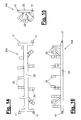
- einen schlanken Spannrahmen in Seitenansicht, Draufsicht und geklappter Stirnansicht.
- Die Erfindung betrifft eine Spannrahmentechnik und eine damit ausgerüstete Bearbeitungsstation (1).
- In
Figur 1 bis 5 ist eine Bearbeitungsstation (1) in verschiedenen Ansichten dargestellt. Hierbei ist aus Übersichtsgründen jeweils nur eine Stationshälfte dargestellt. - Die Bearbeitungsstation (1) ist für beliebige Bearbeitungsprozesse an beliebigen Werkstücken (3) vorgesehen, die z.B. entlang einer durch die Station sich erstreckenden Transferlinie (2) mit geeigneten Förderern zugeführt werden. In der gezeigten Ausführungsform handelt es sich bei den Werkstücken (3) um Fahrzeugkarosserien, insbesondere Rohkarosserien. In der Bearbeitungsstation (1) werden Fügevorgänge an der Karosserie (3) durchgeführt, wobei mittels ein oder mehrerer Spannrahmen (8,9) die Karosserie (3) oder ein oder mehrere Bauteile (4) der Karosserie (3), z.B. eine Seitenwand, an der Arbeitsstelle (35) gespannt und verbunden werden. Ggf. können Bauteile (4) auch mit dem oder den Spannrahmen (8,9) zur Arbeitsstelle (35) zugeführt werden. Die Fügeprozesse zur Verbindung der Bauteile oder Karosserieteile können von beliebiger Art sein, z.B. Schweißen, Kleben, Löten oder dergl..
- Die Karosserie (3) wird in der Bearbeitungsstation (1) an der Arbeitsstelle (35) in geeigneter Weise genau positioniert, so dass eine exakte Ausrichtung zwischen der Karosserie (3) und dem oder den Spannrahmen (8,9) gegeben ist. Die in den Zeichnungen dargestellten Bestandteile der Bearbeitungsstation (1) können nur auf einer Seite oder alternativ auf beiden Seiten der Transferlinie (2) für eine ein- oder beidseitige Bearbeitung der Fahrzeugkarosserie (3) angeordnet sein.
- Die Bearbeitungsstation (1) weist ein Gestell (5) auf, an dem die Spannrahmen (8,9) an der Arbeitsstelle (35) mittels einer Positioniereinrichtung (12) exakt positioniert und fixiert werden können. Die Bearbeitungsstation (1) ist z.B. als Fügestation, insbesondere als sogenannte Geostation ausgestaltet, in der die Karossierteile genau zueinander ausgerichtet und für den Bearbeitungsprozess gespannt werden.
- Das Gestell (5) kann in beliebiger Weise ausgebildet sein. In der gezeigten und bevorzugten Ausführungsform besteht es aus zwei oder mehr frei und aufrecht stehenden Stützsäulen (6), an denen die Spannrahmen (8,9) positioniert und fixiert werden. Bei einer beidseitigen Stationsausbildung sind vier im Rechteck verteilte Stützsäulen (6) vorhanden. Die Stützsäulen (6) sind bodenseitig in geeigneter Weise zur Aufnahme der Spann- und Positionierkräfte abgestützt. Die Abstützung kann starr oder verstellbar sein. Die Stützsäulen (6) können am Stationsboden oder Hallenboden verankert sein. Alternativ können sie an einem Tragelement (7), z.B. einer Bodenplatte angeordnet und befestigt sein. Die Säulenanordnung kann nach ein oder mehreren Richtungen, z.B. in der x- und/oder y-Achse, verstellbar sein, wobei z.B. ein Verstellraster vorhanden ist. Hierüber kann insbesondere der Abstand in x-Richtung zwischen den Stützsäulen (6) zur Anpassung an unterschiedliche Spannrahmengrößen verändert werden.
- Die Bearbeitungsstation (1) weist neben der oder den Arbeitsstellen (35) ein oder mehrere Magazine (26,27) für jeweils ein oder mehrere Spannrahmen (8,9) auf. Ferner ist eine Rahmenwechseleinrichtung (10) vorgesehen, mit der die Spannrahmen (8,9) getauscht und von den Rahmenmagazinen (26,27) zur Arbeitsstelle (35) und zurück transportiert werden können.
- Die Rahmenwechseleinrichtung (10) weist ein oder mehrere mehrachsige Manipulatoren (19) auf, welche die verschiedenen Spannrahmen (8,9) handhaben und mehrachsig führen können. Die Manipulatoren (19) können in beliebig geeigneter Weise ausgebildet sein. Sie haben vorzugsweise mehrere, z.B. fünf oder mehr sich kreuzende Bewegungsachsen, die z.B. orthogonal zueinander ausgerichtet sind. Dies können rotatorische und/oder translatorische Achsen sein. Im gezeigten Ausführungsbeispiel sind sie als mehrachsige, insbesondere sechsachsige Gelenkarmroboter oder sog. Handlingroboter ausgebildet. Sie weisen ein um eine z.B. vertikale Achse auf einem Gestell drehbares Karussell, eine hieran um z.B. eine Horizontalachse schwenkbare Schwinge und einen am Schwingenende wiederum z.B. horizontal schwenkbar gelagerten Ausleger auf. Der Manipulator (19) besitzt eine mehrachsige Roboterhand (20) mit z.B. zwei oder drei Achsen, die z.B. am Auslegerende angeordnet ist.
- Die Roboterhand (20) kann eine geeigneten Wechselkupplung tragen, die mit einer Dockingeinrichtung (25) an den Spannrahmen (8,9) in lösbaren Eingriff treten kann. Über die Wechselkupplung und die Dockingeinrichtung (25) können mittels geeigneter Leitungen und Kupplungselemente Betriebsmittel, z.B. Druckluft, Leistungsstrom, Kühlmittel oder dergl. zugeführt werden. Außerdem können Steuersignale von einer Steuerung, z.B. einer Stations- und/oder Robotersteuerung, übermittelt werden. Die Energie- und Signalversorgung der Spannrahmen (8,9) kann auch auf andere Weise geschaffen werden, z.B. über geeignete Kupplungen und Anschlüsse am Gestell (5), die bei einer Rahmenpositionierung automatisch geschlossen und beim Rahmenwechsel wieder geöffnet werden.
- Der oder die Manipulatoren (19) weisen eine oder mehrere zusätzliche Bewegungsachsen (21) auf. Dies kann z.B. eine gerade oder gebogene Fahrachse oder siebte Achse der Roboter (19) sein, die ggf. parallel zur Transferlinie (2) ausgerichtet ist und auf ein oder beiden Seiten der Transferlinie (2) angeordnet ist. Auf der zusätzlichen Bewegungsachse (21) können sich die Manipulatoren (19) für den Spannrahmentransport zwischen der Arbeitsstelle (35) und dem oder den Rahmenmagazinen (26,27) hin und her bewegen. Die zusätzliche Bewegungsachse (21) kann alternativ zum gezeigten Ausführungsbeispiel durch einen Förderer oder eine andere Transporteinrichtung gebildet werden. Sie muss auch nicht linear verlaufen. Als zusätzliche Achse kann z.B. ein Schwingensystem dienen.
- In den gezeigten Ausführungsbeispielen sind im Arbeitsbereich der Station (1) die Manipulatoren (19) erfindungsgemäß zwischen der Arbeitsstelle (35) bzw. dem Gestell (5) und einer Bearbeitungseinrichtung (11) angeordnet. Die zusätzliche Bewegungsachse (21) verläuft ebenfalls in einem Bereich zwischen dem Gestell (5) und der Bearbeitungseinrichtung (11).
- Die Bearbeitungseinrichtung (11) kann ein oder mehrere mehrachsige Manipulatoren (18) mit Bearbeitungswerkzeugen aufweisen. Dies können z.B. Fügeroboter, insbesondere Schweißroboter sein. Diese Roboter können ebenfalls als sechsachsige Gelenkarmroboter ausgestaltet sein und ggf. auf Sockeln oder mit Zusatzachsen angeordnet sein. Die Reichweite der Fügeroboter (18) und deren Beweglichkeit ist so groß, dass sie die Karosserie (3) an der Arbeitsstelle (35) erreichen können und sich dabei an dem ggf. an der Arbeitsstelle (35) stehenden Handlingroboter (19) vorbeibewegen können. In Ruhestellung geben die Fügeroboter (18) den Fahrweg und sonstigen Bewegungsraum für den Handlingroboter (19) beim Rahmenwechsel frei.
- Der Handlingroboter (19) kann während der Bearbeitung von dem oder den Spannrahmen (8,9) gelöst und von der Arbeitsstelle (35) entfernt werden. Alternativ kann er mit dem oder den Spannrahmen (8,9) verbunden bleiben und an der Arbeitsstelle (35) verharren.
-
Figur 11 bis 16 zeigen verschiedene Varianten von Spannrahmen (8,9) in verschiedenen Ansichten und Positionen am Gestell (5). Die Spannrahmen (8,9) sind mit ein oder mehreren Spannern (23) ausgerüstet, mit denen die Karosserieteile gespannt werden können. Die beweglichen Spannerelemente können in beliebig geeigneter Weise angetrieben werden. Die Energieversorgung kann in der vorerwähnten Art über die Dockingeinrichtung (25), die z.B. als Energie- und Wechselkupplung ausgebildet ist oder auf andere Weise über geeignete Anschlüsse im Gestell (5) erfolgen. Die Spanner (23) können insbesondere selbst verriegelnde Antriebe, z.B. Kniehebelantriebe, haben, welche die beweglichen Spannerteile in der Spannposition festhalten. Die Selbstverriegelung ermöglicht nach der Spannrahmenpositionierung ein Trennen der Energieversorgung und erlaubt ein Lösen des Handlingroboters (19) vom Spannrahmen (8,9). Der Handlingroboter (19) kann dann die Arbeitsstelle (35) verlassen und den Zugang für die Bearbeitungseinrichtung (11) vollständig frei machen. - Die Spannrahmen (8,9) können eine längliche und schmale oder schlanke Form aufweisen. Sie können z.B. in den Varianten von
Figur 11 ,12 und14 bis 16 einen balkenartigen Träger (22) aufweisen, der z.B. im wesentlichen eine I-Form hat. Die Spannrahmen (8,9) werden am Gestell (5) vorzugsweise mit einer im wesentlichen horizontalen Ausrichtung positioniert, wobei sich der Träger (22) horizontal und parallel zur Transferlinie (2) erstreckt. An den Trägerende sind quer stehende und in der Gestellposition aufrechte Trägerarme angeordnet, die am Ende Zentrierelemente (17) für die nachfolgend erläuterte Positioniereinrichtung (12) tragen. - Der Träger (22) ist z.B. als torsions- und biegesteifer sowie kastenförmiger Hohlkörper ausgebildet. Die Spanner (23) können einzeln oder gruppenweise in beliebiger Ausrichtung und Position am Träger (22) starr oder mit einer Zusatzachse beweglich angeordnet sein. Vorzugsweise sind sie an der Trägervörderseite angeordnet.
Figur 14 verdeutlicht in der Seitendarstellung, dass die Spanner (23) in ihrer Verteilung und Anordnung eine geweihartige Spannerkontur bilden können.Figur 15 zeigt in der geklappten Stirnansicht die Spannerausrichtung zur Karosserie. InFigur 1 bis 13 sind die Spanner (23) schematisch als Umrisslinie der gesamten Spannergruppe dargestellt. - Durch die schlanke Spannrahmenform sind unterschiedliche Positioniermöglichkeiten gegeben. In der Variante von
Figur 11 ist ein einzelner schlanker Spannrahmen (8) mit seinem Träger (22) liegend und horizontal im oberen Bereich des Gestells (5) bzw. der stummelartigen Stützsäulen (6) angeordnet. Seine Spanner (23) dienen zum Spannen der oberen Karosseriebereiche. Unterhalb des Spannrahmens (8) können am Gestell (5), insbesondere an der Bodenplatte (7) weitere Spanner (24) angeordnet sein, die für den unteren Karosseriebereich oder Schwellerbereich vorgesehen sind und z.B. die Bodengruppe der Karosserie (3) mit der Seitenwand spannen. Die Spanner (24) können starr oder ein- oder mehrachsig verstellbar angeordnet sein. Sie können dabei ein oder mehrere eigene steuerbare lineare und/oder rotatorische Verstellachsen, z.B. in x-, y- und/oder z-Richtung haben, wie dies inFigur 11 angedeutet ist. Damit kann eine Feinpositionierung in Anpassung an wechselnde Fahrzeugtypen erreicht werden. - Die gezeigte Spannkonfiguration hat Vorteile für Karosserietypen, die z.B. im Bodengruppen- oder Schwellerbereich im wesentlichen die gleiche Form aufweisen und sich im oberen Karosseriebereich von Typ zu Typ unterscheiden. Derartige Typenunterschiede bestehen z.B. bei 2- oder 4-türigen Karosserievarianten oder Schrägheck- und Stufenheckvarianten oder dergl. der gleichen Fahrzeugbaureihe. In diesen Fällen ist bei einem Wechsel des Karosserietyps nur der Spannrahmen (8) auszutauschen. Die Spanngeometrie der unteren weiteren Spanner (24) kann dabei gleich bleiben oder in der vorerwähnten Weise angepasst, insbesondere zugestellt werden.
-
Figur 12 zeigt eine Abwandlung vonFigur 11 , bei der zwei schlanke Spannrahmen (8,9) übereinander im Gestell (5) positioniert sind. Der untere Spannrahmen (9) ersetzt die weiteren Spanner (24) und kann gemeinsam oder unabhängig vom oberen Spannrahmen (8) bei einem Typwechsel getauscht werden. In Variation zur gezeigten Ausführungsform können mehr als zwei Spannrahmen (8,9) übereinander angeordnet werden. In weiterer Abwandlung können mehrere Spannrahmen (8,9) alternativ oder zusätzlich nebeneinander im Gestell (5) positioniert werden. -
Figur 13 zeigt eine Variante der Spannrahmen (8,9) in einer breiteren Ausführung, die z.B. für kleine Fahrzeuge geeignet ist. In diesem Fall sind mehrere horizontal ausgerichtete Träger oder Rahmenteile mit endseitigen Rahmenverbindungen vorgesehen. Hierdurch kann z.B. ein in der Seitenansicht rechteckiger umlaufender Rahmen gebildet werden. Die Dockingeinrichtung (25) ist auch hier an geeigneter Stelle und vorzugsweise mittig sowie an der Rahmenrückseite angeordnet. Der größere Spannrahmen (8,9) vonFigur 13 ist z.B. in der Lage, die komplette Seitenwand (4) der Karosserie (3) zu spannen. Ein solcher Spannrahmen (8,9) eignet sich auch besonders für eine Bauteilzuführung bei der Rahmenzustellung bzw. beim Rahmenwechsel. - Die Positioniereinrichtung (12) dient zur exakten Positionierung der Spannrahmen (8,9) am Gestell (5). Sie bietet ein oder mehrere Zentrierungen (13,14,15). Außerdem ist eine Fixiereinrichtung (nicht dargestellt) vorhanden, mit der die eingenommene Rahmenposition gesichert werden kann. Dies kann z.B. ein steuerbarer Spannhebel oder dergl. sein. Wie
Figur 11 bis 13 beispielhaft verdeutlichen, sind für jeden Spannrahmen (8,9) vier Zentrierungen (13,14,15) vorhanden. Die beiden oberen y-Zentrierungen (13) wirken in Richtung der Y-Achse und quer zur Transferlinie (2). Die eine untere Zentrierung ist als x,y,z-Zentrierung mit Wirkung in allen drei Raumachsen X,Y,Z ausgebildet. Auf der gegenüberliegenden Seite an der anderen Stützsäule (6) ist eine x,y-Zentrierung (14) an der Rahmenunterseite angeordnet. Über die Zentrierungen (13,14,15) ist eine Positionierung in allen sechs translatorischen und rotatorischen Achsen möglich. - Zur Bildung der Zentrierungen (13,14,15) sind jeweils zusammenwirkende Zentrierelemente (16) am Gestell und insbesondere an den Stützsäulen (6) sowie Zentrierelemente (17) an den Spannrahmen (8,9) vorhanden.
Figur 8 und 9 zeigen als vergrößerte Ausschnitte zuFigur 7 Detaildarstellungen des Zentrierelementes (16,17) und der y-Zentrierungen (13). - In
Figur 1 bis 7 sind verschiedene Varianten der Rahmenmagazine (26,27) dargestellt. Die Rahmenmagazine (26,27) können beidseits der Arbeitsstelle (35) angeordnet und identisch oder unterschiedlich ausgebildet sein. Sie können alternativ auch nur auf einer Stationsseite sich befinden. Bei einer doppelseitigen Stationsausbildung können vier oder weniger Rahmenmagazine (26,27) vorhanden sein. - Die Rahmenmagazine (26,27) weisen jeweils mehrere Rahmenhalter (31) auf, die vorzugsweise für eine aufrechte Spannrahmenlage und Speicherung konzipiert sind. Die Rahmenhalter (31) sind in den gezeigten Ausführungsformen stationär angeordnet und bestehen jeweils aus zwei vertikalen Tragsäulen (32) mit Stützelementen (33) für die Spannrahmen (8,9). Zum Einlagern werden die z.B. länglichen Spannrahmen (8,9) vom Handlingroboter (19) aus ihrer horizontalen Arbeitsstellung nach der Abnahme vom Gestell (5) um ca. 90° gedreht und mit einer im wesentlichen vertikalen Ausrichtung an die Rahmenhalter (31) übergeben, in denen sie stehend oder hängend gehalten werden können. Die Stützelemente (33) an den Tragsäulen (32) können an die Zentrierelemente (17) der Spannrahmen (8,9) oder an andere Spannrahmenteile angepasst sein und für eine exakte Spannrahmenpositionierung im Rahmenhalter (31) sorgen. Hierfür können z.B. die in
Figur 11 im oberen Spannrahmenbereich dargestellten Zentrierungen (14,15) sorgen. An der Rahmenunterseite können Anschläge (34), z.B. y-Anschläge vorhanden sein. Durch die exakte Positionierung können die Spannrahmen (8,9) vom Handlingroboter (19) in definierter Lage gegriffen und aufgenommen oder abgegeben werden. -
Figur 1 bis 5 verdeutlichen eine Magazinausbildung, in der ein Teil der Rahmenhalter (31) in ein oder mehreren Reihen auf ein oder beiden Seiten der zusätzlichen Bewegungsachse (21) in einer achsparallelen Lage angeordnet sind. Benachbarte Rahmenhalter (31) können gemeinsame Tragsäulen (32) haben. Alternativ oder zusätzlich ist es möglich, mehrere Rahmehalter (31) in einem Bogen anzuordnen. Eine solche Anordnung kann sich z.B. am Endbereich der zusätzlichen Bewegungsachse (21) befinden. - In den Magazinen (26,27) kann durch die platzsparende Gestaltung eine Vielzahl von Lagerplätzen für die unterschiedlichen Spannrahmen (8,9) gebildet werden. Hierbei können die Magazine (26,27) auch in Magazinbereiche (28,29,30) unterteilt werden, in denen untereinander gleichartige Spannrahmen (8,9) angeordnet sind.
Figur 7 zeigt beispielhaft eine solche Anordnung. Im Rahmenbereich (28) sind Spannrahmen (8) untergebracht, die z.B. gemäßFigur 12 für den oberen Karosseriebereich vorgesehen sind. Diese schmalen Spannrahmen (8) sind in reihenförmig angeordneten Rahmenhaltern (31) aufgenommen. Untereinander unterscheiden sich die Spannrahmen (8) hinsichtlich des Karosserietyps und der hierfür vorgesehenen Spannergeometrie. Im anderen Magazinbereich (29), der aus einer Reihenanordnung von Rahmenhaltern (31) auf der anderen Seite der zusätzlichen Bewegungsachse (21) besteht, sind die anderen schmalen Spannrahmen (9) aufgenommen, die gemäßFigur 12 für den Schwellerbereich vorgesehen sind. Im dritten Magazinbereich (30), der z.B. eine bogenförmige Anordnung von Rahmenhaltern (31) zeigt, sind größere Spannrahmen (8) aufgenommen, die z.B. der Variante vonFigur 13 entsprechen. - Abwandlungen der gezeigten und beschriebenen Ausführungsformen sind im Rahmen der Ansprüche in verschiedener Weise möglich. Zum einen können die Gestaltungsmerkmale der verschiedenen Ausführungsformen beliebig untereinander vertauscht oder kombiniert werden. Ferner ist es möglich, bei kleineren Bearbeitungsstationen (1) mit nur einem Manipulator oder Handlingroboter (19) auszukommen. Ferner sind andere Magazinformen möglich, die auch Bewegungsachsen haben können, z.B. in der Ausbildung als Trommelmagazin. In die Magazine (26,27) oder an anderer Stelle der Bearbeitungsstation (1) kann außerdem eine Bauteilzuführung (nicht dargestellt) integriert sein, mit der Bauteile (4) von außen zugeführt und an die Spannrahmen (8,9) für eine gemeinsame Zustellung an der Arbeitsstelle (35) übergeben werden. Ferner kann das Gestell (5) in anderer Weise ausgebildet sein. Variationsfähig sind auch die anderen Stationskomponenten, insbesondere die Bearbeitungseinrichtung (11).
-
- 1
- Bearbeitungsstation, Fügestation
- 2
- Transferlinie
- 3
- Werkstück, Karosserie
- 4
- Bauteil, Seitenwand
- 5
- Gestell
- 6
- Stützsäule
- 7
- Tragelement, Bodenplatte
- 8
- Spannrahmen
- 9
- Spannrahmen
- 10
- Rahmenwechseleinrichtung
- 11
- Bearbeitungseinrichtung
- 12
- Positioniereinrichtung
- 13
- Zentrierung, y-Zentrierung
- 14
- Zentrierung, y,z-Zentrierung
- 15
- Zentrierung, x,y,z-Zentrierung
- 16
- Zentrierelement an Gestell
- 17
- Zentrierelement an Spannrahmen
- 18
- Manipulator, Fügeroboter
- 19
- Manipulator, Handlingroboter
- 20
- Manipulatorhand, Roboterhand
- 21
- Bewegungsachse, Fahrachse
- 22
- Träger
- 23
- Spanner an Spannrahmen
- 24
- Spanner an Gestell
- 25
- Dockingeinrichtung
- 26
- Rahmenmagazin
- 27
- Rahmenmagazin
- 28
- Magazinbereich
- 29
- Magazinbereich
- 30
- Magazinbereich
- 31
- Rahmenhalter
- 32
- Säule
- 33
- Stützelement
- 34
- Anschlag, y-Anschlag
- 35
- Arbeitsstelle
Claims (14)
- Bearbeitungsstation, insbesondere Fügestation, für Werkstücke (3) von Fahrzeugkarosserien, wobei die Bearbeitungsstation (1) ein Gestell (5) mit mindestens einer Arbeitsstelle (35), mehrere Spannrahmen (8,9), mindestens ein Rahmenmagazin (26,27), eine Rahmenwechseleinrichtung (10) und eine Bearbeitungseinrichtung (11) für die Werkstücke (3) aufweist, wobei die Rahmenwechseleinrichtung (10) ein oder mehrere mehrachsige Manipulatoren (19) aufweist, wobei die Spannrahmen (8,9) eine Dockingeinrichtung (25) zur lösbaren Verbindung mit dem Manipulator (19) besitzen und wobei eine Positioniereinrichtung (12) zur Positionierung und Fixierung der Spannrahmen (8,9) am Gestell (5) vorgesehen ist, wobei der Manipulator (19) eine zusätzliche Bewegungsachse (21), insbesondere eine Fahrachse, für seinen Transport zwischen der Arbeitsstelle (35) und dem Rahmenmagazin (26,27) aufweist, dadurch gekennzeichnet, dass die Bewegungsachse (21) zwischen der Bearbeitungseinrichtung (11) und der Arbeitsstelle (35) angeordnet ist.
- Bearbeitungsstation nach Anspruch 1, dadurch gekennzeichnet, dass der Manipulator (19) als Gelenkarmroboter mit sechs oder mehr Achsen ausgebildet ist und eine mehrachsige Roboterhand (20) mit einer Wechselkupplung aufweist.
- Bearbeitungsstation nach Anspruch 1 oder 2, dadurch gekennzeichnet, dass die Bearbeitungseinrichtung (11) ein oder mehrere mehrachsige Manipulatoren (18), insbesondere Fügeroboter, aufweist.
- Bearbeitungsstation nach Anspruch 1, 2 oder 3, dadurch gekennzeichnet, dass die Spannrahmen (8,9) eine längliche schmale Form aufweisen.
- Bearbeitungsstation nach einem der vorhergehenden Ansprüche, dadurch gekennzeichnet, dass die Spannrahmen (8,9) einen balkenartigen Träger (22) mit ein oder mehreren Spannern (23) aufweisen.
- Bearbeitungsstation nach Anspruch 5, dadurch gekennzeichnet, dass der Träger (22) im wesentlichen eine I-Form aufweist.
- Bearbeitungsstation nach einem der vorhergehenden Ansprüche, dadurch gekennzeichnet, dass die Spannrahmen (8,9) am Gestell (5) mit im wesentlichen horizontaler Ausrichtung positionierbar sind.
- Bearbeitungsstation nach einem der vorhergehenden Ansprüche, dadurch gekennzeichnet, dass mehrere Spannrahmen (8,9) am Gestell (5) übereinander und/oder nebeneinander positionierbar sind.
- Bearbeitungsstation nach einem der vorhergehenden Ansprüche, dadurch gekennzeichnet, dass das Gestell (5) ein oder mehrere frei stehende Stützsäulen (6) aufweist.
- Bearbeitungsstation nach Anspruch 9, dadurch gekennzeichnet, dass die Stützsäulen (6) verstellbar an einem Tragelement (7), insbesondere einer Bodenplatte, angeordnet sind.
- Bearbeitungsstation nach Anspruch 10, dadurch gekennzeichnet, dass am Gestell (5), insbesondere am Tragelement (7), ein oder mehrere Spanner (24) angeordnet sind.
- Bearbeitungsstation nach Anspruch 11, dadurch gekennzeichnet, dass die weiteren Spanner (24) ein oder mehrere Verstellachsen aufweisen.
- Bearbeitungsstation nach Anspruch 10 oder 11, dadurch gekennzeichnet, dass die weiteren Spanner (24) unterhalb des Spannrahmens (8) angeordnet sind.
- Bearbeitungsstation nach einem der vorhergehenden Ansprüche, dadurch gekennzeichnet, dass die Dockingeinrichtung (25) als Energie- und Wechselkupplung ausgebildet ist.
Priority Applications (1)
| Application Number | Priority Date | Filing Date | Title |
|---|---|---|---|
| PL07725909T PL2027008T3 (pl) | 2006-06-12 | 2007-06-08 | Stacja obróbkowa, zwłaszcza stacja do łączenia |
Applications Claiming Priority (2)
| Application Number | Priority Date | Filing Date | Title |
|---|---|---|---|
| DE202006009312U DE202006009312U1 (de) | 2006-06-12 | 2006-06-12 | Bearbeitungsstation, insbesondere Fügestation |
| PCT/EP2007/005064 WO2007144114A2 (de) | 2006-06-12 | 2007-06-08 | Bearbeitungsstation, insbesondere fügestation für fahrzeugkarosserien |
Publications (2)
| Publication Number | Publication Date |
|---|---|
| EP2027008A2 EP2027008A2 (de) | 2009-02-25 |
| EP2027008B1 true EP2027008B1 (de) | 2014-11-05 |
Family
ID=38370448
Family Applications (1)
| Application Number | Title | Priority Date | Filing Date |
|---|---|---|---|
| EP07725909.1A Revoked EP2027008B1 (de) | 2006-06-12 | 2007-06-08 | Bearbeitungsstation, insbesondere fügestation |
Country Status (5)
| Country | Link |
|---|---|
| EP (1) | EP2027008B1 (de) |
| DE (1) | DE202006009312U1 (de) |
| ES (1) | ES2528488T3 (de) |
| PL (1) | PL2027008T3 (de) |
| WO (1) | WO2007144114A2 (de) |
Families Citing this family (13)
| Publication number | Priority date | Publication date | Assignee | Title |
|---|---|---|---|---|
| DE202007009015U1 (de) | 2007-06-26 | 2008-11-06 | Kuka Systems Gmbh | Fügestation für Karosseriebauteile |
| DE102008032909B4 (de) * | 2008-07-12 | 2016-07-14 | Bayerische Motoren Werke Aktiengesellschaft | Verfahren und Fertigungseinrichtung zum Fertigen von Rohkarosserien von Fahrzeugen |
| CN102049697B (zh) * | 2010-11-25 | 2012-03-21 | 扬州华宇管件有限公司 | 一种小口径弯头机械加工夹具 |
| DE102012015392A1 (de) * | 2012-08-03 | 2014-05-15 | Daimler Ag | Rohbaustation zum Herstellen von Kraftwagen-Rohbauten und Verfahren zum Betreiben einer Rohbaustation |
| CN103264275B (zh) * | 2013-04-27 | 2015-07-08 | 浙江工业大学 | 万向脚轮自动组装装置 |
| CN103317373B (zh) * | 2013-06-28 | 2015-11-18 | 江苏中核利柏特股份有限公司 | 车床加工用弯头夹具 |
| DE102015002928B4 (de) * | 2015-03-03 | 2019-03-07 | EXPERT-TÜNKERS GmbH | Transportvorrichtung zum Bewegen von Werkstücken für den Karosseriebau der Kfz-Industrie |
| CN104985368B (zh) * | 2015-07-17 | 2017-01-04 | 柳州海特迪桢瑟汽车部件有限公司 | 一种多自由度联动焊接装置 |
| CN105033638B (zh) * | 2015-08-25 | 2016-06-01 | 福州华鹰重工机械有限公司 | 脚轮自动组装机 |
| EP3219436B1 (de) | 2016-03-19 | 2018-11-07 | Expert-Tünkers GmbH | Vorrichtung zum motorischen drehen eines starren werkstückträgers in entgegengesetzten drehrichtungen |
| DE102018210596B4 (de) * | 2018-06-28 | 2025-02-27 | Bayerische Motoren Werke Aktiengesellschaft | Verfahren zur temporären Stationierung eines Spannrahmens |
| CN112207738B (zh) * | 2020-10-15 | 2022-03-29 | 山东煜宝嘉重工股份有限公司 | 机械配件制造用多工位夹持固定装置 |
| WO2026087043A1 (de) | 2024-10-24 | 2026-04-30 | Volkswagen Aktiengesellschaft | Rohbaustation für kraftfahrzeuge, verfahren zum betreiben einer rohbaustation und computerprogrammprodukt |
Family Cites Families (13)
| Publication number | Priority date | Publication date | Assignee | Title |
|---|---|---|---|---|
| DE3720175A1 (de) * | 1987-06-16 | 1988-12-29 | Kuka Schweissanlagen & Roboter | Vorrichtung zum automatischen foerdern von spannrahmen oder dergleichen in transferstrassen |
| DE9105490U1 (de) | 1991-05-03 | 1992-09-10 | KUKA Schweissanlagen GmbH, 86165 Augsburg | Bearbeitungsstation für Werkstücke, insbesondere Fahrzeugkarosserien in einer Transferlinie |
| DE4418755A1 (de) | 1994-05-28 | 1995-11-30 | Kuka Schweissanlagen & Roboter | Verfahren und Vorrichtung zum Zuführen, Spannen und Bearbeiten von Bauteilen einer Fahrzeugkarosserie |
| CA2282571A1 (en) * | 1997-03-22 | 1998-10-01 | Thyssen Industrie Ag | Device and method for feeding, clamping and processing, particularly for geometric welding of automobile body components in a work station |
| DE19713860A1 (de) | 1997-04-04 | 1998-10-08 | Kuka Schweissanlagen Gmbh | Verfahren und Vorrichtung zum Fertigen von komplexen Werkstücken |
| FI112334B (fi) * | 1997-04-08 | 2003-11-28 | Abb Research Ltd | Menetelmä ja järjestely auton korin kokoonpanoon |
| DE29806823U1 (de) * | 1998-04-16 | 1999-09-09 | KUKA Schweissanlagen GmbH, 86165 Augsburg | Vorrichtung zum Hantieren mindestens eines Spannrahmens, insbesondere für die Montage von Rohkarosserien von Fahrzeugen |
| DE19917908A1 (de) * | 1998-09-03 | 2000-03-23 | Thyssen Industrie | Anlage für den flexiblen Zusammenbau von Kfz-Karosserien |
| DE19938684B4 (de) * | 1999-08-14 | 2009-05-14 | Volkswagen Ag | Flexibler Träger zur Handhabung von Karosserien oder Teilkarosserien bei der Fertigung von Fahrzeugen |
| SE0002097D0 (sv) | 2000-06-05 | 2000-06-05 | Abb Ab | Förfarande och anläggning för montering |
| AT411035B (de) | 2001-07-18 | 2003-09-25 | Va Tech Transport & Montagesysteme Gmbh & Co | Bearbeitungsstation |
| KR20040053274A (ko) | 2001-11-08 | 2004-06-23 | 다이하츠고교 가부시키가이샤 | 차체조립부착방법 |
| US7100271B2 (en) | 2003-09-23 | 2006-09-05 | Valiant Corporation | Automotive vehicle framing system |
-
2006
- 2006-06-12 DE DE202006009312U patent/DE202006009312U1/de not_active Expired - Lifetime
-
2007
- 2007-06-08 PL PL07725909T patent/PL2027008T3/pl unknown
- 2007-06-08 EP EP07725909.1A patent/EP2027008B1/de not_active Revoked
- 2007-06-08 ES ES07725909.1T patent/ES2528488T3/es active Active
- 2007-06-08 WO PCT/EP2007/005064 patent/WO2007144114A2/de not_active Ceased
Also Published As
| Publication number | Publication date |
|---|---|
| WO2007144114A3 (de) | 2008-03-27 |
| PL2027008T3 (pl) | 2015-05-29 |
| ES2528488T3 (es) | 2015-02-10 |
| WO2007144114A2 (de) | 2007-12-21 |
| DE202006009312U1 (de) | 2007-10-25 |
| EP2027008A2 (de) | 2009-02-25 |
Similar Documents
| Publication | Publication Date | Title |
|---|---|---|
| WO2007144114A2 (de) | Bearbeitungsstation, insbesondere fügestation für fahrzeugkarosserien | |
| DE3506314C2 (de) | ||
| EP0968073B1 (de) | Verfahren und vorrichtung zum zuführen, spannen und bearbeiten, insbesondere zum geometrie-schweissen von bauteilen von fahrzeugkarosserien in einer bearbeitungsstation | |
| EP1843936B1 (de) | Fertigungsverfahren und fertigungseinrichtung für bauteile | |
| EP1827769B1 (de) | Handlingvorrichtung und verfahren zum mehrachsigen handhaben und führen von auf einer trageeinrichtung angeorndeten werkstücken | |
| EP0977651B1 (de) | Verfahren und vorrichtung zum fertigen von komplexen werkstücken | |
| EP0760770B1 (de) | Verfahren und vorrichtung zum zuführen, spannen und bearbeiten von bauteilen einer fahrzeugkarosserie | |
| EP0579160B1 (de) | Bearbeitungsstation für Fahrzeugkarosserien in einer Transferlinie | |
| EP2137053A2 (de) | Verfahren und vorrichtung zum befördern beweglicher werkzeuge | |
| DE202008003143U1 (de) | Laserbearbeitungseinrichtung | |
| EP0585584B1 (de) | Bearbeitungsstation für Fahrzeugkarosserien in einer Transferlinie | |
| DE102005042179B4 (de) | Flexible Fertigungszelle für die Bearbeitung von Bauteilen, insbesondere von Fahrzeugkarosserien | |
| DE202008006717U1 (de) | Bearbeitungsstation | |
| DE60313266T2 (de) | Verfahren zum Konstruieren einer Produktionslinie in einem flexiblen Herstellungssystem | |
| DE202009005237U1 (de) | Bearbeitungseinrichtung | |
| EP3672763B1 (de) | Positionier- und spannsystem und verfahren | |
| WO2009000513A1 (de) | Fügestation für karosseriebauteile | |
| DE20306257U1 (de) | Bearbeitungsvorrichtung | |
| WO2008098605A1 (de) | Positioniereinrichtung | |
| DE202006005835U1 (de) | Bearbeitungsstation | |
| WO2004069464A1 (de) | Spannrahmen mit luftkissenanordnung | |
| DE202007017864U1 (de) | Bearbeitungseinrichtung | |
| DE29913612U1 (de) | Bearbeitungsstation für Fahrzeugkarosserien | |
| DE20301127U1 (de) | Flexible Anlagenzelle |
Legal Events
| Date | Code | Title | Description |
|---|---|---|---|
| PUAI | Public reference made under article 153(3) epc to a published international application that has entered the european phase |
Free format text: ORIGINAL CODE: 0009012 |
|
| 17P | Request for examination filed |
Effective date: 20080326 |
|
| AK | Designated contracting states |
Kind code of ref document: A2 Designated state(s): AT BE BG CH CY CZ DE DK EE ES FI FR GB GR HU IE IS IT LI LT LU LV MC MT NL PL PT RO SE SI SK TR |
|
| AX | Request for extension of the european patent |
Extension state: AL BA HR MK RS |
|
| RIN1 | Information on inventor provided before grant (corrected) |
Inventor name: WIEDMEIER, ARTHUR Inventor name: MAISCHBERGER, JOHANN |
|
| 17Q | First examination report despatched |
Effective date: 20090603 |
|
| DAX | Request for extension of the european patent (deleted) | ||
| GRAP | Despatch of communication of intention to grant a patent |
Free format text: ORIGINAL CODE: EPIDOSNIGR1 |
|
| RIC1 | Information provided on ipc code assigned before grant |
Ipc: B62D 65/02 20060101AFI20140610BHEP Ipc: B23K 37/04 20060101ALI20140610BHEP Ipc: B62D 65/18 20060101ALN20140610BHEP Ipc: B23K 101/00 20060101ALI20140610BHEP |
|
| INTG | Intention to grant announced |
Effective date: 20140627 |
|
| GRAS | Grant fee paid |
Free format text: ORIGINAL CODE: EPIDOSNIGR3 |
|
| GRAA | (expected) grant |
Free format text: ORIGINAL CODE: 0009210 |
|
| AK | Designated contracting states |
Kind code of ref document: B1 Designated state(s): AT BE BG CH CY CZ DE DK EE ES FI FR GB GR HU IE IS IT LI LT LU LV MC MT NL PL PT RO SE SI SK TR |
|
| REG | Reference to a national code |
Ref country code: GB Ref legal event code: FG4D Free format text: NOT ENGLISH |
|
| REG | Reference to a national code |
Ref country code: CH Ref legal event code: EP |
|
| REG | Reference to a national code |
Ref country code: AT Ref legal event code: REF Ref document number: 694447 Country of ref document: AT Kind code of ref document: T Effective date: 20141115 |
|
| REG | Reference to a national code |
Ref country code: IE Ref legal event code: FG4D Free format text: LANGUAGE OF EP DOCUMENT: GERMAN |
|
| REG | Reference to a national code |
Ref country code: DE Ref legal event code: R096 Ref document number: 502007013555 Country of ref document: DE Effective date: 20141218 |
|
| REG | Reference to a national code |
Ref country code: SE Ref legal event code: TRGR Ref country code: ES Ref legal event code: FG2A Ref document number: 2528488 Country of ref document: ES Kind code of ref document: T3 Effective date: 20150210 |
|
| REG | Reference to a national code |
Ref country code: NL Ref legal event code: VDEP Effective date: 20141105 |
|
| REG | Reference to a national code |
Ref country code: LT Ref legal event code: MG4D |
|
| PG25 | Lapsed in a contracting state [announced via postgrant information from national office to epo] |
Ref country code: NL Free format text: LAPSE BECAUSE OF FAILURE TO SUBMIT A TRANSLATION OF THE DESCRIPTION OR TO PAY THE FEE WITHIN THE PRESCRIBED TIME-LIMIT Effective date: 20141105 Ref country code: LT Free format text: LAPSE BECAUSE OF FAILURE TO SUBMIT A TRANSLATION OF THE DESCRIPTION OR TO PAY THE FEE WITHIN THE PRESCRIBED TIME-LIMIT Effective date: 20141105 Ref country code: FI Free format text: LAPSE BECAUSE OF FAILURE TO SUBMIT A TRANSLATION OF THE DESCRIPTION OR TO PAY THE FEE WITHIN THE PRESCRIBED TIME-LIMIT Effective date: 20141105 Ref country code: PT Free format text: LAPSE BECAUSE OF FAILURE TO SUBMIT A TRANSLATION OF THE DESCRIPTION OR TO PAY THE FEE WITHIN THE PRESCRIBED TIME-LIMIT Effective date: 20150305 Ref country code: IS Free format text: LAPSE BECAUSE OF FAILURE TO SUBMIT A TRANSLATION OF THE DESCRIPTION OR TO PAY THE FEE WITHIN THE PRESCRIBED TIME-LIMIT Effective date: 20150305 |
|
| PG25 | Lapsed in a contracting state [announced via postgrant information from national office to epo] |
Ref country code: LV Free format text: LAPSE BECAUSE OF FAILURE TO SUBMIT A TRANSLATION OF THE DESCRIPTION OR TO PAY THE FEE WITHIN THE PRESCRIBED TIME-LIMIT Effective date: 20141105 Ref country code: GR Free format text: LAPSE BECAUSE OF FAILURE TO SUBMIT A TRANSLATION OF THE DESCRIPTION OR TO PAY THE FEE WITHIN THE PRESCRIBED TIME-LIMIT Effective date: 20150206 Ref country code: CY Free format text: LAPSE BECAUSE OF FAILURE TO SUBMIT A TRANSLATION OF THE DESCRIPTION OR TO PAY THE FEE WITHIN THE PRESCRIBED TIME-LIMIT Effective date: 20141105 |
|
| REG | Reference to a national code |
Ref country code: PL Ref legal event code: T3 |
|
| REG | Reference to a national code |
Ref country code: DE Ref legal event code: R026 Ref document number: 502007013555 Country of ref document: DE |
|
| PG25 | Lapsed in a contracting state [announced via postgrant information from national office to epo] |
Ref country code: SK Free format text: LAPSE BECAUSE OF FAILURE TO SUBMIT A TRANSLATION OF THE DESCRIPTION OR TO PAY THE FEE WITHIN THE PRESCRIBED TIME-LIMIT Effective date: 20141105 Ref country code: CZ Free format text: LAPSE BECAUSE OF FAILURE TO SUBMIT A TRANSLATION OF THE DESCRIPTION OR TO PAY THE FEE WITHIN THE PRESCRIBED TIME-LIMIT Effective date: 20141105 Ref country code: RO Free format text: LAPSE BECAUSE OF FAILURE TO SUBMIT A TRANSLATION OF THE DESCRIPTION OR TO PAY THE FEE WITHIN THE PRESCRIBED TIME-LIMIT Effective date: 20141105 Ref country code: EE Free format text: LAPSE BECAUSE OF FAILURE TO SUBMIT A TRANSLATION OF THE DESCRIPTION OR TO PAY THE FEE WITHIN THE PRESCRIBED TIME-LIMIT Effective date: 20141105 Ref country code: DK Free format text: LAPSE BECAUSE OF FAILURE TO SUBMIT A TRANSLATION OF THE DESCRIPTION OR TO PAY THE FEE WITHIN THE PRESCRIBED TIME-LIMIT Effective date: 20141105 |
|
| PLBI | Opposition filed |
Free format text: ORIGINAL CODE: 0009260 |
|
| 26 | Opposition filed |
Opponent name: ABB TECHNOLOGY AG Effective date: 20150729 |
|
| PLAX | Notice of opposition and request to file observation + time limit sent |
Free format text: ORIGINAL CODE: EPIDOSNOBS2 |
|
| PG25 | Lapsed in a contracting state [announced via postgrant information from national office to epo] |
Ref country code: IT Free format text: LAPSE BECAUSE OF FAILURE TO SUBMIT A TRANSLATION OF THE DESCRIPTION OR TO PAY THE FEE WITHIN THE PRESCRIBED TIME-LIMIT Effective date: 20141105 |
|
| PLAF | Information modified related to communication of a notice of opposition and request to file observations + time limit |
Free format text: ORIGINAL CODE: EPIDOSCOBS2 |
|
| PG25 | Lapsed in a contracting state [announced via postgrant information from national office to epo] |
Ref country code: MC Free format text: LAPSE BECAUSE OF FAILURE TO SUBMIT A TRANSLATION OF THE DESCRIPTION OR TO PAY THE FEE WITHIN THE PRESCRIBED TIME-LIMIT Effective date: 20141105 |
|
| REG | Reference to a national code |
Ref country code: CH Ref legal event code: PL |
|
| PG25 | Lapsed in a contracting state [announced via postgrant information from national office to epo] |
Ref country code: LU Free format text: LAPSE BECAUSE OF FAILURE TO SUBMIT A TRANSLATION OF THE DESCRIPTION OR TO PAY THE FEE WITHIN THE PRESCRIBED TIME-LIMIT Effective date: 20150608 Ref country code: SI Free format text: LAPSE BECAUSE OF FAILURE TO SUBMIT A TRANSLATION OF THE DESCRIPTION OR TO PAY THE FEE WITHIN THE PRESCRIBED TIME-LIMIT Effective date: 20141105 |
|
| PLBB | Reply of patent proprietor to notice(s) of opposition received |
Free format text: ORIGINAL CODE: EPIDOSNOBS3 |
|
| REG | Reference to a national code |
Ref country code: IE Ref legal event code: MM4A |
|
| PG25 | Lapsed in a contracting state [announced via postgrant information from national office to epo] |
Ref country code: CH Free format text: LAPSE BECAUSE OF NON-PAYMENT OF DUE FEES Effective date: 20150630 Ref country code: IE Free format text: LAPSE BECAUSE OF NON-PAYMENT OF DUE FEES Effective date: 20150608 Ref country code: LI Free format text: LAPSE BECAUSE OF NON-PAYMENT OF DUE FEES Effective date: 20150630 |
|
| REG | Reference to a national code |
Ref country code: FR Ref legal event code: PLFP Year of fee payment: 10 |
|
| REG | Reference to a national code |
Ref country code: AT Ref legal event code: MM01 Ref document number: 694447 Country of ref document: AT Kind code of ref document: T Effective date: 20150608 |
|
| PLAB | Opposition data, opponent's data or that of the opponent's representative modified |
Free format text: ORIGINAL CODE: 0009299OPPO |
|
| R26 | Opposition filed (corrected) |
Opponent name: ABB TECHNOLOGY AG Effective date: 20150729 |
|
| PG25 | Lapsed in a contracting state [announced via postgrant information from national office to epo] |
Ref country code: AT Free format text: LAPSE BECAUSE OF NON-PAYMENT OF DUE FEES Effective date: 20150608 |
|
| PG25 | Lapsed in a contracting state [announced via postgrant information from national office to epo] |
Ref country code: MT Free format text: LAPSE BECAUSE OF FAILURE TO SUBMIT A TRANSLATION OF THE DESCRIPTION OR TO PAY THE FEE WITHIN THE PRESCRIBED TIME-LIMIT Effective date: 20141105 |
|
| PLAB | Opposition data, opponent's data or that of the opponent's representative modified |
Free format text: ORIGINAL CODE: 0009299OPPO |
|
| REG | Reference to a national code |
Ref country code: FR Ref legal event code: PLFP Year of fee payment: 11 |
|
| PG25 | Lapsed in a contracting state [announced via postgrant information from national office to epo] |
Ref country code: HU Free format text: LAPSE BECAUSE OF FAILURE TO SUBMIT A TRANSLATION OF THE DESCRIPTION OR TO PAY THE FEE WITHIN THE PRESCRIBED TIME-LIMIT; INVALID AB INITIO Effective date: 20070608 Ref country code: BG Free format text: LAPSE BECAUSE OF FAILURE TO SUBMIT A TRANSLATION OF THE DESCRIPTION OR TO PAY THE FEE WITHIN THE PRESCRIBED TIME-LIMIT Effective date: 20141105 |
|
| R26 | Opposition filed (corrected) |
Opponent name: ABB TECHNOLOGY AG Effective date: 20150729 |
|
| PG25 | Lapsed in a contracting state [announced via postgrant information from national office to epo] |
Ref country code: BE Free format text: LAPSE BECAUSE OF NON-PAYMENT OF DUE FEES Effective date: 20150630 |
|
| PG25 | Lapsed in a contracting state [announced via postgrant information from national office to epo] |
Ref country code: TR Free format text: LAPSE BECAUSE OF FAILURE TO SUBMIT A TRANSLATION OF THE DESCRIPTION OR TO PAY THE FEE WITHIN THE PRESCRIBED TIME-LIMIT Effective date: 20141105 |
|
| RIC2 | Information provided on ipc code assigned after grant |
Ipc: B62D 65/02 20060101AFI20170810BHEP Ipc: B23K 101/00 20060101ALI20170810BHEP Ipc: B23K 37/04 20060101ALI20170810BHEP Ipc: B62D 65/18 20060101ALN20170810BHEP |
|
| RIC2 | Information provided on ipc code assigned after grant |
Ipc: B23K 37/04 20060101ALI20170811BHEP Ipc: B23K 101/00 20060101ALI20170811BHEP Ipc: B62D 65/18 20060101ALN20170811BHEP Ipc: B62D 65/02 20060101AFI20170811BHEP |
|
| RIC2 | Information provided on ipc code assigned after grant |
Ipc: B62D 65/18 20060101ALN20180306BHEP Ipc: B23K 101/00 20060101ALI20180306BHEP Ipc: B23K 37/04 20060101ALI20180306BHEP Ipc: B62D 65/02 20060101AFI20180306BHEP |
|
| RIC2 | Information provided on ipc code assigned after grant |
Ipc: B62D 65/18 20060101ALN20180312BHEP Ipc: B23K 37/04 20060101ALI20180312BHEP Ipc: B23K 101/00 20060101ALI20180312BHEP Ipc: B62D 65/02 20060101AFI20180312BHEP |
|
| APBM | Appeal reference recorded |
Free format text: ORIGINAL CODE: EPIDOSNREFNO |
|
| APBP | Date of receipt of notice of appeal recorded |
Free format text: ORIGINAL CODE: EPIDOSNNOA2O |
|
| APAH | Appeal reference modified |
Free format text: ORIGINAL CODE: EPIDOSCREFNO |
|
| REG | Reference to a national code |
Ref country code: FR Ref legal event code: PLFP Year of fee payment: 12 |
|
| APBM | Appeal reference recorded |
Free format text: ORIGINAL CODE: EPIDOSNREFNO |
|
| APBP | Date of receipt of notice of appeal recorded |
Free format text: ORIGINAL CODE: EPIDOSNNOA2O |
|
| APBQ | Date of receipt of statement of grounds of appeal recorded |
Free format text: ORIGINAL CODE: EPIDOSNNOA3O |
|
| APBQ | Date of receipt of statement of grounds of appeal recorded |
Free format text: ORIGINAL CODE: EPIDOSNNOA3O |
|
| PGFP | Annual fee paid to national office [announced via postgrant information from national office to epo] |
Ref country code: DE Payment date: 20190528 Year of fee payment: 13 Ref country code: PL Payment date: 20190403 Year of fee payment: 13 |
|
| PGFP | Annual fee paid to national office [announced via postgrant information from national office to epo] |
Ref country code: SE Payment date: 20190611 Year of fee payment: 13 Ref country code: FR Payment date: 20190510 Year of fee payment: 13 |
|
| PGFP | Annual fee paid to national office [announced via postgrant information from national office to epo] |
Ref country code: ES Payment date: 20190701 Year of fee payment: 13 Ref country code: GB Payment date: 20190605 Year of fee payment: 13 |
|
| PLAB | Opposition data, opponent's data or that of the opponent's representative modified |
Free format text: ORIGINAL CODE: 0009299OPPO |
|
| R26 | Opposition filed (corrected) |
Opponent name: ABB SCHWEIZ AG Effective date: 20150729 |
|
| APAY | Date of receipt of notice of appeal deleted |
Free format text: ORIGINAL CODE: EPIDOSDNOA2O |
|
| APBA | Date of receipt of statement of grounds of appeal deleted |
Free format text: ORIGINAL CODE: EPIDOSDNOA3O |
|
| APBU | Appeal procedure closed |
Free format text: ORIGINAL CODE: EPIDOSNNOA9O |
|
| APBY | Invitation to file observations in appeal sent |
Free format text: ORIGINAL CODE: EPIDOSNOBA2O |
|
| REG | Reference to a national code |
Ref country code: DE Ref legal event code: R119 Ref document number: 502007013555 Country of ref document: DE |
|
| GBPC | Gb: european patent ceased through non-payment of renewal fee |
Effective date: 20200608 |
|
| PG25 | Lapsed in a contracting state [announced via postgrant information from national office to epo] |
Ref country code: FR Free format text: LAPSE BECAUSE OF NON-PAYMENT OF DUE FEES Effective date: 20200630 Ref country code: GB Free format text: LAPSE BECAUSE OF NON-PAYMENT OF DUE FEES Effective date: 20200608 |
|
| RDAF | Communication despatched that patent is revoked |
Free format text: ORIGINAL CODE: EPIDOSNREV1 |
|
| STAA | Information on the status of an ep patent application or granted ep patent |
Free format text: STATUS: THE PATENT HAS BEEN GRANTED |
|
| REG | Reference to a national code |
Ref country code: DE Ref legal event code: R103 Ref document number: 502007013555 Country of ref document: DE Ref country code: DE Ref legal event code: R064 Ref document number: 502007013555 Country of ref document: DE |
|
| PG25 | Lapsed in a contracting state [announced via postgrant information from national office to epo] |
Ref country code: SE Free format text: LAPSE BECAUSE OF NON-PAYMENT OF DUE FEES Effective date: 20200609 Ref country code: DE Free format text: LAPSE BECAUSE OF NON-PAYMENT OF DUE FEES Effective date: 20210101 |
|
| RDAG | Patent revoked |
Free format text: ORIGINAL CODE: 0009271 |
|
| STAA | Information on the status of an ep patent application or granted ep patent |
Free format text: STATUS: PATENT REVOKED |
|
| REG | Reference to a national code |
Ref country code: FI Ref legal event code: MGE |
|
| 27W | Patent revoked |
Effective date: 20210517 |
|
| REG | Reference to a national code |
Ref country code: SE Ref legal event code: EUG |
|
| REG | Reference to a national code |
Ref country code: AT Ref legal event code: MA03 Ref document number: 694447 Country of ref document: AT Kind code of ref document: T Effective date: 20210517 |
|
| PG25 | Lapsed in a contracting state [announced via postgrant information from national office to epo] |
Ref country code: ES Free format text: LAPSE BECAUSE OF NON-PAYMENT OF DUE FEES Effective date: 20200609 |
|
| PG25 | Lapsed in a contracting state [announced via postgrant information from national office to epo] |
Ref country code: PL Free format text: LAPSE BECAUSE OF NON-PAYMENT OF DUE FEES Effective date: 20200608 |