EP2026936B1 - Vorrichtung zum schneiden von kartoffeln oder ähnlichem gemüse - Google Patents
Vorrichtung zum schneiden von kartoffeln oder ähnlichem gemüse Download PDFInfo
- Publication number
- EP2026936B1 EP2026936B1 EP20070755779 EP07755779A EP2026936B1 EP 2026936 B1 EP2026936 B1 EP 2026936B1 EP 20070755779 EP20070755779 EP 20070755779 EP 07755779 A EP07755779 A EP 07755779A EP 2026936 B1 EP2026936 B1 EP 2026936B1
- Authority
- EP
- European Patent Office
- Prior art keywords
- impeller assembly
- cutting
- paddles
- cutting head
- knife
- Prior art date
- Legal status (The legal status is an assumption and is not a legal conclusion. Google has not performed a legal analysis and makes no representation as to the accuracy of the status listed.)
- Active
Links
- 238000005520 cutting process Methods 0.000 title claims abstract description 84
- 235000002595 Solanum tuberosum Nutrition 0.000 title description 11
- 244000061456 Solanum tuberosum Species 0.000 title description 11
- 235000012015 potatoes Nutrition 0.000 title description 9
- 235000013311 vegetables Nutrition 0.000 title description 3
- 235000013305 food Nutrition 0.000 claims abstract description 27
- 239000012530 fluid Substances 0.000 claims description 2
- 230000007423 decrease Effects 0.000 claims 1
- 239000000463 material Substances 0.000 description 5
- 238000007906 compression Methods 0.000 description 4
- 230000006835 compression Effects 0.000 description 4
- 238000010276 construction Methods 0.000 description 4
- 239000011435 rock Substances 0.000 description 4
- 230000000712 assembly Effects 0.000 description 3
- 238000000429 assembly Methods 0.000 description 3
- 230000000694 effects Effects 0.000 description 3
- 238000000034 method Methods 0.000 description 3
- 230000007935 neutral effect Effects 0.000 description 3
- 235000013606 potato chips Nutrition 0.000 description 3
- 229910045601 alloy Inorganic materials 0.000 description 2
- 239000000956 alloy Substances 0.000 description 2
- 238000005266 casting Methods 0.000 description 2
- 230000005484 gravity Effects 0.000 description 2
- 230000001050 lubricating effect Effects 0.000 description 2
- 238000004519 manufacturing process Methods 0.000 description 2
- 229910000906 Bronze Inorganic materials 0.000 description 1
- 229920002472 Starch Polymers 0.000 description 1
- 238000010521 absorption reaction Methods 0.000 description 1
- 238000013459 approach Methods 0.000 description 1
- 239000010974 bronze Substances 0.000 description 1
- 238000004140 cleaning Methods 0.000 description 1
- 239000000356 contaminant Substances 0.000 description 1
- 238000010411 cooking Methods 0.000 description 1
- KUNSUQLRTQLHQQ-UHFFFAOYSA-N copper tin Chemical compound [Cu].[Sn] KUNSUQLRTQLHQQ-UHFFFAOYSA-N 0.000 description 1
- 230000003247 decreasing effect Effects 0.000 description 1
- 230000001419 dependent effect Effects 0.000 description 1
- 235000013399 edible fruits Nutrition 0.000 description 1
- 238000005469 granulation Methods 0.000 description 1
- 230000003179 granulation Effects 0.000 description 1
- 230000003116 impacting effect Effects 0.000 description 1
- -1 manganese aluminum Chemical compound 0.000 description 1
- 235000013622 meat product Nutrition 0.000 description 1
- 229910052751 metal Inorganic materials 0.000 description 1
- 239000002184 metal Substances 0.000 description 1
- 235000019684 potato crisps Nutrition 0.000 description 1
- 238000005096 rolling process Methods 0.000 description 1
- 235000019698 starch Nutrition 0.000 description 1
- 239000008107 starch Substances 0.000 description 1
- XLYOFNOQVPJJNP-UHFFFAOYSA-N water Substances O XLYOFNOQVPJJNP-UHFFFAOYSA-N 0.000 description 1
Images


Classifications
-
- B—PERFORMING OPERATIONS; TRANSPORTING
- B26—HAND CUTTING TOOLS; CUTTING; SEVERING
- B26D—CUTTING; DETAILS COMMON TO MACHINES FOR PERFORATING, PUNCHING, CUTTING-OUT, STAMPING-OUT OR SEVERING
- B26D7/00—Details of apparatus for cutting, cutting-out, stamping-out, punching, perforating, or severing by means other than cutting
- B26D7/26—Means for mounting or adjusting the cutting member; Means for adjusting the stroke of the cutting member
- B26D7/2614—Means for mounting the cutting member
-
- B—PERFORMING OPERATIONS; TRANSPORTING
- B26—HAND CUTTING TOOLS; CUTTING; SEVERING
- B26D—CUTTING; DETAILS COMMON TO MACHINES FOR PERFORATING, PUNCHING, CUTTING-OUT, STAMPING-OUT OR SEVERING
- B26D1/00—Cutting through work characterised by the nature or movement of the cutting member or particular materials not otherwise provided for; Apparatus or machines therefor; Cutting members therefor
- B26D1/01—Cutting through work characterised by the nature or movement of the cutting member or particular materials not otherwise provided for; Apparatus or machines therefor; Cutting members therefor involving a cutting member which does not travel with the work
- B26D1/02—Cutting through work characterised by the nature or movement of the cutting member or particular materials not otherwise provided for; Apparatus or machines therefor; Cutting members therefor involving a cutting member which does not travel with the work having a stationary cutting member
- B26D1/03—Cutting through work characterised by the nature or movement of the cutting member or particular materials not otherwise provided for; Apparatus or machines therefor; Cutting members therefor involving a cutting member which does not travel with the work having a stationary cutting member with a plurality of cutting members
-
- B—PERFORMING OPERATIONS; TRANSPORTING
- B26—HAND CUTTING TOOLS; CUTTING; SEVERING
- B26D—CUTTING; DETAILS COMMON TO MACHINES FOR PERFORATING, PUNCHING, CUTTING-OUT, STAMPING-OUT OR SEVERING
- B26D1/00—Cutting through work characterised by the nature or movement of the cutting member or particular materials not otherwise provided for; Apparatus or machines therefor; Cutting members therefor
- B26D1/01—Cutting through work characterised by the nature or movement of the cutting member or particular materials not otherwise provided for; Apparatus or machines therefor; Cutting members therefor involving a cutting member which does not travel with the work
- B26D1/12—Cutting through work characterised by the nature or movement of the cutting member or particular materials not otherwise provided for; Apparatus or machines therefor; Cutting members therefor involving a cutting member which does not travel with the work having a cutting member moving about an axis
- B26D1/25—Cutting through work characterised by the nature or movement of the cutting member or particular materials not otherwise provided for; Apparatus or machines therefor; Cutting members therefor involving a cutting member which does not travel with the work having a cutting member moving about an axis with a non-circular cutting member
- B26D1/34—Cutting through work characterised by the nature or movement of the cutting member or particular materials not otherwise provided for; Apparatus or machines therefor; Cutting members therefor involving a cutting member which does not travel with the work having a cutting member moving about an axis with a non-circular cutting member moving about an axis parallel to the line of cut
- B26D1/36—Cutting through work characterised by the nature or movement of the cutting member or particular materials not otherwise provided for; Apparatus or machines therefor; Cutting members therefor involving a cutting member which does not travel with the work having a cutting member moving about an axis with a non-circular cutting member moving about an axis parallel to the line of cut and rotating continuously in one direction during cutting, e.g. mounted on a rotary cylinder
-
- B—PERFORMING OPERATIONS; TRANSPORTING
- B26—HAND CUTTING TOOLS; CUTTING; SEVERING
- B26D—CUTTING; DETAILS COMMON TO MACHINES FOR PERFORATING, PUNCHING, CUTTING-OUT, STAMPING-OUT OR SEVERING
- B26D7/00—Details of apparatus for cutting, cutting-out, stamping-out, punching, perforating, or severing by means other than cutting
- B26D7/06—Arrangements for feeding or delivering work of other than sheet, web, or filamentary form
- B26D7/0691—Arrangements for feeding or delivering work of other than sheet, web, or filamentary form by centrifugal force
-
- B—PERFORMING OPERATIONS; TRANSPORTING
- B26—HAND CUTTING TOOLS; CUTTING; SEVERING
- B26D—CUTTING; DETAILS COMMON TO MACHINES FOR PERFORATING, PUNCHING, CUTTING-OUT, STAMPING-OUT OR SEVERING
- B26D1/00—Cutting through work characterised by the nature or movement of the cutting member or particular materials not otherwise provided for; Apparatus or machines therefor; Cutting members therefor
- B26D1/0006—Cutting members therefor
- B26D2001/0053—Cutting members therefor having a special cutting edge section or blade section
-
- B—PERFORMING OPERATIONS; TRANSPORTING
- B26—HAND CUTTING TOOLS; CUTTING; SEVERING
- B26D—CUTTING; DETAILS COMMON TO MACHINES FOR PERFORATING, PUNCHING, CUTTING-OUT, STAMPING-OUT OR SEVERING
- B26D7/00—Details of apparatus for cutting, cutting-out, stamping-out, punching, perforating, or severing by means other than cutting
- B26D7/06—Arrangements for feeding or delivering work of other than sheet, web, or filamentary form
-
- Y—GENERAL TAGGING OF NEW TECHNOLOGICAL DEVELOPMENTS; GENERAL TAGGING OF CROSS-SECTIONAL TECHNOLOGIES SPANNING OVER SEVERAL SECTIONS OF THE IPC; TECHNICAL SUBJECTS COVERED BY FORMER USPC CROSS-REFERENCE ART COLLECTIONS [XRACs] AND DIGESTS
- Y10—TECHNICAL SUBJECTS COVERED BY FORMER USPC
- Y10S—TECHNICAL SUBJECTS COVERED BY FORMER USPC CROSS-REFERENCE ART COLLECTIONS [XRACs] AND DIGESTS
- Y10S83/00—Cutting
- Y10S83/929—Particular nature of work or product
- Y10S83/932—Edible
-
- Y—GENERAL TAGGING OF NEW TECHNOLOGICAL DEVELOPMENTS; GENERAL TAGGING OF CROSS-SECTIONAL TECHNOLOGIES SPANNING OVER SEVERAL SECTIONS OF THE IPC; TECHNICAL SUBJECTS COVERED BY FORMER USPC CROSS-REFERENCE ART COLLECTIONS [XRACs] AND DIGESTS
- Y10—TECHNICAL SUBJECTS COVERED BY FORMER USPC
- Y10T—TECHNICAL SUBJECTS COVERED BY FORMER US CLASSIFICATION
- Y10T83/00—Cutting
- Y10T83/647—With means to convey work relative to tool station
- Y10T83/6473—Centrifugal feed to tangential tool [e.g., "Beria" type]
Definitions
- the present invention generally relates to cutting methods and equipment. More particularly, this invention relates to an apparatus equipped with an impeller assembly that positions and orients elongate food products prior to encountering a cutting device that produces size-reduced products of generally consistent thickness.
- slicing equipment adapted for cutting root vegetables such as potatoes into thin slices suitable for making potato chips (also known as potato crisps).
- a widely used machine for this purpose is commercially available from Urschel Laboratories, Inc., under the name Urschel Model CC®.
- the Model CC® is a centrifugal-type slicer capable of producing uniform slices, strip cuts, shreds and granulations of a wide variety of food products at high production capacities.
- the Model CC® can make use of substantially round potatoes to produce the desired circular chip shape with a minimum amount of scrap. Descriptions pertaining to the construction and operation of the Model CC®, including improved embodiments thereof, are contained in U.S. Patent Nos. 5,694,824 and 6,968,765 .
- FIGs 1 and 3 are perspective views of an impeller 10 and cutting head 12, respectively, of types that can be used in the Model CC® machine.
- the impeller 10 is coaxially mounted within the cutting head 12, which is generally annular-shaped with cutting knives 14 mounted on its perimeter.
- the impeller 10 rotates within the cutting head 12, which remains stationary.
- Each knife 14 projects radially inward toward the impeller 10 and in a direction generally opposite the direction of rotation of the impeller 10, and defines a cutting edge at its radially innermost extremity.
- the impeller 10 has generally radially-oriented paddles 16 with faces 34 that engage and direct food products (e.g., potatoes) 36 radially outward against the knives 14 of the cutting head 12 as the impeller 10 rotates.
- the paddles 16 are shown as oriented to have what is termed herein a negative pitch, which as viewed in Figure 2 denotes that the face 34 of each paddle 16 has a radially innermost extent angled away from the direction of rotation of the impeller 10 relative to a radial 38 of the impeller 10 terminating at the radially outermost extent of the face 34. Such an orientation has been found to be preferred with the impeller 10 and cutting head 12 of Figures 1 through 3 .
- the impeller 10 is typically formed as a casting, such as from a manganese aluminum bronze (MAB) alloy, and therefore has a unitary construction.
- MAB manganese aluminum bronze
- the cutting head 12 shown in Figure 3 comprises a lower support ring 18, an upper mounting ring 20, and circumferentially-spaced support segments 22.
- the knives 14 of the cutting head 12 are individually secured with clamping assemblies 26 to the support segments 22, which are pivotally attached to the support and mounting rings 18 and 20, such as with one or more coaxial pins (not shown) that engage holes in the support and/or mounting rings 18 and 20.
- the orientation of a support segment 22 can be adjusted to alter the radial location of the cutting edge of its knife 14 with respect to the axis of the cutting head 12, thereby controlling the thickness of the sliced food product
- adjustment can be achieved with an adjusting screw and/or pin 24 located circumferentially behind the pivot pins.
- FIG. 3 further shows gate insert strips 23 mounted to each support segment 22 immediately downstream of each knife 14.
- the gate insert strips 23 do not cover the entire axial extent of the cutting head 12, but instead define an opening 25 at each of their lower ends through which rocks and other debris that settle by gravity toward the bottom of the impeller 10 can feed through the cutting head 12 without damaging the knives 14.
- FIGS. 9 and 10 are cross-sectional views through a portion of the cutting head 12 looking toward the lower support ring 18.
- Figure 9 shows a knife 14 held in place with a clamping assembly 26 comprising inner and outer holders 27 and 28 secured with bolts 29 to a support segment 22, generally as described in U.S. Patent No. 6,968,765 and particularly in reference to Figure 7 of this prior patent.
- Figure 10 shows a knife 14 encased in a plastic cartridge 30, which helps to protect the knife 14 from damage by rocks and other debris that may be embedded in or otherwise present with the food products being fed through the impeller 10.
- the knife 14 and its plastic cartridge 30 are held in place between a pair of holders 27 and 28, with the radially outer holder 28 being forcibly held in place on the support segment 22 with a clamping rod 32.
- the clamping rod 32 is shown oriented perpendicular to the support and mounting rings 18 and 20, and secured to the radially inner holder 27 with a fastener 31. Rotating a lever 33 creates a camming action that forces the outer holder 28 outward against the rod 32, and forcing the outer holder 28 against the knife 14.
- the knives 14 are disposable and must be replaced to maintain the cutting efficiency of the cutting head 12 and the quality of the sliced food product.
- the cutting edge 15 of each knife 14 is shown in Figures 9 and 10 as bering formed to have a double bevel.
- the trajectory 35 of slices produced at the knife edge 15 is free of any obstacles downstream and radially outward from a plane defined by the outer surface of the outer holder 28.
- the plastic cartridge 30 deflects slices away from the clamping rod 32.
- the plastic cartridge 30 avoids this by deflecting slices away from the clamping rod 32, the compressibility of the plastic material reduces the precision with which the cutting edges 15 of the knives 14 can be located, making production of slices with consistent thicknesses difficult.
- Other variables that can affect the operation of the Model CC® slicing machine and/or reduce the consistency of slices include the presence of contaminants such as stones embedded or mixed in with the products, which can damage the cutting edges of the knives, and the use of small products that tend to roll within the impeller 10.
- Figures 1 and 2 are perspective and cross-sectional views, respectively, of an existing impeller for the Model CC® slicer.
- Figure 3 is a perspective view of an existing cutting head for the Model CC® slicer.
- FIGS. 4A , 4B , and 4C are perspective, side, and cross-sectional views, respectively, of an impeller assembly suitable for use with the Model CC® slicer In accordance with a preferred embodiment of the invention.
- Figure 4D shows plan, perspective, and cross-sectional views of a deflector for use with the impeller assembly of Figures 4A and 4B in accordance with an optional aspect of the invention.
- FIGS 4E , 4F , and 4G are perspective, side, and cross-sectional views, respectively, of an impeller assembly suitable for use with the Model CC® slicer in accordance with an alternative embodiment of the Invention.
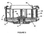
- Figure 5 is a cross-sectional view of the impeller assembly of Figures 4A , 4B , and 4C assembled with the deflector of Figure 4D and mounted within the cutting head of Figure 3 .
- Figures 6A and 6B are isolated top and side views, respectively, of an impeller paddle of the impeller assembly of Figures 4A , 4B , and 4C .
- Figure 7 is an isolated side view of an impeller paddle of the impeller assembly of Figures 4E , 4F , and 4G .
- Figure 8 is a cross-sectional view of an edge portion of the impeller assembly of Figures 4A , 4B , and 4C , schematically showing a single impeller paddle engaged with food products of various sizes.
- Figures 9 and 10 are cross-sectional views showing portions of existing cutting heads used with the Model CC® slicer.
- Figures 11 , 12 , and 13 are cross-sectional views showing portions of modified cutting heads suitable for use with the Model CC® slicer, and particularly the impeller assembly of Figures 4A , 4B , and 4C , in accordance with different embodiments of the invention.
- Figures 14 and 15 are side and cross-sectional views, respectively, of a clamping assembly shown in Figures 13 .
- FIGS 4A , 4B , and 4C show a modified impeller assembly 40 in accordance with the present invention.
- the impeller assembly 40 is configured for rotation within cutting heads similar to the cutting head 12 of Figure 3 , as well as cutting heads 42 configured in accordance with Figures 11 through 13 .
- the impeller assembly 40 has generally radially-oriented paddles 46 with faces 60 that engage and direct food products (e.g., potatoes) radially outward against knives of the cutting head as the impeller assembly 40 rotates.
- the paddles 46 are significantly different in construction and configuration from the prior art paddles 16 of Figures 1 and 2 .
- the impeller assembly 40 is preferably constructed of individually formed paddles 46 mounted and secured between a pair of annular-shaped plates 48 and 50.
- the impeller 40 and its components can be formed by processes other than casting, and formed of various materials in addition to commonly-used MAB alloys.
- Each of the paddles 46 is shown in Figure 4A as being individually mounted with bolts 51 and pins 52 to a corresponding set of mounting holes 53 machined in the plates 48 and 50.
- the placement of the mounting holes 53 determines the orientation or pitch of each paddle face 60 relative to a radial 64 of the impeller assembly 40 terminating at the radially outermost extent of the paddle face 60.
- the pitch of the paddle faces 60 can be negative (such as the orientation seen in Figure 2 ), neutral (meaning that the face 60 of each paddle 46 lies in the radial 64 of the impeller assembly 40), or positive (such as the orientation seen in Figures 4C , in which the radially innermost extent 66 of each paddle face 60 is angled toward the direction of rotation of the impeller assembly 40 relative to the radial 64).
- a single set of holes 53 is provided for each paddle 46 so that the paddles 46 for a given impeller assembly 40 are limited to having a negative, neutral, or positive pitch, as may be desired.
- multiple sets of mounting holes 53 are provided in the plates 48 and 50 to enable reorientation of the pitch of each paddle 46 on the impeller assembly 40.
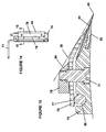
- FIGS 6A and 6B show an individual paddle 46, which can be seen as symmetric in the axial direction of the impeller assembly 40 (from top to bottom in Figure 4A and 4B ).
- the radially innermost extent 66 of each paddle 46 is generally straight and axially-oriented. Suitable dimensions for the paddle 46 will depend in part on the size of the food products being processed, and therefore can vary considerably. For accommodating food products with diameters up to about four inches (about ten centimeters), a suitable radial width for each paddle 46 is up to about two inches, as measured from the radially outermost extent of the paddle face 60 to a line at the intersection of the paddle face 60 and a radius defining the radially innermost extent 66 of the paddle 46.
- FIG 7 shows an individual paddle 46 of the alternative embodiment of Figures 4E , 4F , and 4G .
- the alternative paddle 46 of Figure 7 is asymmetric in the axial direction of the impeller assembly 40 (from top to bottom in Figure 4E and 4F ), in contrast to the paddles 16 of Figures 4A through 4C , 6A, and 6B .
- the radially innermost extent 66 of each alternative paddle 46 is generally straight and axially-oriented adjacent the lower plate 48, but with a boundary 68 adjacent the upper plate 50 that curves radially outward as it approaches the upper plate 50. Though not required, this shape and contour for the innermost extent of each paddle 46 has the desirable effect of reducing damage to food products being processed.
- the posts 54 are preferably replaceable, such as by threading into a face 58 machined into the radially outermost extent of each paddle 46.
- the posts 54 have generally conical shapes, and are preferably angled so that a profile of its conical shape is coplanar with the face 60 of its paddle 46, as seen in Figure 6 .
- each paddle 46 has axially-oriented grooves 62 to inhibit food product from rotating while engaged by the paddle 46.
- the distances between adjacent grooves 62 is shown as decreasing in the direction toward the outside diameter of the impeller assembly 40, since smaller food products (such as potatoes two inches (about five centimeters) and smaller) are usually rounder in shape and have less mass, and are therefore more likely to roll while they are engaged by a paddle 46. It is believed that, in combination, the grooves 62 on impeller paddles 46 having a positive pitch provide an optimal anti-rolling effect when small potatoes are being fed through the impeller assembly 40.
- Figure 4D represents a deflector 90 for use with either of the impeller assemblies 40 of this invention.
- the deflector 90 is tapered to generally have an inverted cone-shape to direct food products radially outward toward the impeller paddles 46.
- the deflector 90 is further formed to have a central semispherical depression or recess 92.
- the function of the recess 92 is to cause water (or another lubricating fluid commonly used in food processing) originally directed downward toward the recess 92 to be redirected radially outward toward the upper ends of the paddles 46, and thereafter cascade down the vertical surfaces of the paddles 46 to provide a lubricating and cleaning effect.
- the deflector 90 has a central bore 94 for centrally locating the deflector 90 on the lower plate 48 of the impeller assembly 40 as shown in Figure 5 , and a countersunk bore 96 for receiving a bolt (not shown) to secure the deflector 90 to the lower plate 48.
- Figure 5 schematically represents the impeller assembly 40 of Figures 4A through 4C equipped with the deflector 90 of Figure 4D and coaxially and concentrically mounted for rotation within the cutting head 12 of Figure 3 .
- the cutting head 12 is supported on a stationary frame 13, while the impeller assembly 40 is coupled to a drive shaft 41.
- the righthand side of Figure 5 is a cross-section of gate insert strip 23 mounted to a support segment 22 immediately adjacent a knife (not shown), and shows the gate insert strip 23 as not covering the entire axial extent of the paddles 46. Instead, the gate insert strip 23 defines an opening 25 at its lower end through which rocks and other debris that settle by gravity toward the bottom of the impeller assembly 40 can feed through the cutting head 12 without damaging the knife.
- Figure 8 schematically represents a plan view of the impeller assembly 40 of Figures 4E through 4G , with the upper plate 50 removed and round potatoes 72 of different diameters engaged with one of its paddles 46. From Figure 8 , it can be seen that a four-inch diameter potato is tangent to the face 60 of the paddle 46 at a point on the intersection of the face 60 with a radius of the straight inner boundary 66 of the paddle 46, evidencing that the paddle 46 is sized to accommodate food products with diameters up to four inches (about 10 cm).
- the paddle 46 is shown in Figure 8 as having a positive pitch of about five degrees.
- the paddle 46 would be angled an additional five degrees, providing a positive ten-degree pitch. If the paddle 46 were mounted to the next set of mounting holes 53 below the paddle 46 (as viewed in Figure 8 ), the paddle 46 would have a neutral pitch.
- FIGS 11 , 12 , and 13 are coss-sectional views showing portions of cutting heads 42 configured with different knife clamping hardware according to various embodiments of the invention.
- knives 44 are secured with a pair of holders 74 and 76, with the radially outer holder 76 being forcibly held in place on its support segment 70 with a clamping rod 78, essentially as described for Figure 10 .
- none of the knives 44 represented in Figures 11 through 13 are sheathed in a plastic cartridge as done in Figure 10 .
- the intent of omitting the plastic cartridge 30 of Figure 10 is to more accurately locate the cutting edge 45 of each knife 44 relative to the axis of the cutting head 42 to achieve improved slice thickness accuracy and consistency.
- the pliability of plastic materials renders the plastic cartridge 30 compressible, which reduces to some extent that accuracy with which the knife cutting edges 45 can be radially located with respect to the axis of the cutting head 42. Therefore, eliminating the cartridge 30 and forming the knife 44 and its holders 74 and 76 of substantially incompressible materials, such as metal, eliminates the dimensional changes that occur from compression under the clamping load of the rod 78, and ensures more accurate positioning of the knife cutting edges 45.
- a conventional double-beveled knife 44 is shown essentially similar to the knife 14 of Figure 9 .
- the trajectories 35 of slices traveling downstream from the knife 44 is such that slices are likely to hit the clamping rod 78.
- Figure 12 shows the clamping rod 78 as having a half-round cross-section, which allows the clamping rod 78 to have a sufficiently lower profile that is radially inward from the trajectories 35 of slices exiting the knife 44
- the knife 44 of Figure 12 is also supported by an insert 80, such that the knife 44 is between the insert 80 and the inner holder 74.
- the insert 80 serves to protect the edge of the inner holder 74 from stones or other debris that are often unintentionally fed through the impeller assembly 40 along with food products.
- the knife 44 shown in Figure 13 is beveled only on its radially outer surface 82.
- a single-beveled knife edge 45 is believed to produce a cleaner slice and reduce the compression of food products during the slicing operation observed with the double-beveled knives 14 and 44 of Figures 9 through 12 .
- the single-beveled knife 44 of Figure 13 does not deflect slices to the extent that the double-beveled knives 14 and 44 of Figures 9 through 12 are capable.
- Figure 13 shows the clamping rod 78 as generally having the form of a rectilinear bar with a tapered leading edge 84, resulting in the rod 78 having a sufficiently lower profile proximate to the knife 44 that is radially inward from the trajectories 35 of slices exiting the knife 44.
- Figures 14 and 15 illustrate the clamping action performed by the clamping rod 78 in more detail.
- the embodiment shown in Figures 14 and 15 combine the insert 80 of Figure 12 with the tapered clamping rod 78 of Figure 13 .
- the lever 77 has forced one end of the outer holder 76 against the clamping rod 78, which in turn forces the opposite end of the outer holder 76 into engagement with the knife 44, forcing the knife 44 against the inner holder 74.
- the knife 44 can be release by rotating the lever 77 clockwise (as viewed in Figure 15 ), such that a flat 86 on the lever 77 faces the outer holder 76, releasing the outer holder 76 from its engagement with the clamping rod 78.
Landscapes
- Life Sciences & Earth Sciences (AREA)
- Forests & Forestry (AREA)
- Engineering & Computer Science (AREA)
- Mechanical Engineering (AREA)
- Crushing And Pulverization Processes (AREA)
- Food-Manufacturing Devices (AREA)
- Apparatuses For Bulk Treatment Of Fruits And Vegetables And Apparatuses For Preparing Feeds (AREA)
- Preparation Of Fruits And Vegetables (AREA)
- Storage Of Fruits Or Vegetables (AREA)
- Formation And Processing Of Food Products (AREA)
- Nonmetal Cutting Devices (AREA)
Claims (12)
- Schneidgerät mit einem ringförmigen Schneidkopf (12, 42) und einer Laufradanordnung (40), die koaxial mit dem Schneidkopf (12, 42) montiert ist, um die Drehung um eine Achse des Schneidkopfes (12, 42) in einer Drehrichtung relativ zum Schneidkopf (12, 42) zu erlauben, wobei der Schneidkopf (12, 42) wenigstens ein Messer (14, 44) aufweist, das sich radial nach innen von dem Schneidkopf (12, 42) in Richtung auf die Laufradanordnung (40) erstreckt, in einer Richtung, die der Drehrichtung der Laufradanordnung (40) entgegengesetzt ist, wobei das Messer (14, 44) an einem radial innersten Ende eine Schneidkante (15, 45) sowie eine radiale äußere Front (82) aufweist, die eine Flugbahnebene (35) für Scheiben definiert, die von den Lebensmittelprodukten (72) durch die Schneidkante (15, 45) entfernt wurden, wobei die Laufradanordnung (40) Folgendes umfasst Schaufelblätter (46) zum Befördern runder Lebensmittelprodukte (72) radial nach außen in Richtung auf den Schneidkopf (12, 42), wobei jedes Schaufelblatt (46) ein radial äußeres Ende (58) aufweist, das dem Außenrand der Laufradanordnung (40) benachbart ist, ein entgegengesetzt geneigtes radiales inneres Ende (66) und eine Frontfläche (60) zwischen dem radial inneren und dem radial äußeren Ende (58, 66) und gegenüberliegend der Drehrichtung der Laufradanordnung (40); gekennzeichnet durch eine Mehrzahl von an dem radial äußeren Ende (58) jedes der Schaufelblätter (46) befestigten entfernbaren Stiften (54), die sich in eine radial äußere Richtung der Laufradanordnung (40) erstrecken.
- Schneidgerät nach Anspruch 1, bei dem jedes der Schaufelblätter Vertiefungen aufweist, die quer zum Radius der Laufradanordnung verlaufen, wobei die Vertiefungen (62) voneinander beabstandet sind und der Abstand zwischen einander benachbarten Vertiefungen (62) sich in radial nach außen gerichteter Richtung der Laufradanordnung (40) verringert.
- Schneidgerät nach Anspruch 1, bei dem jede der Frontflächen (60) der Schaufelblätter (46) in einer Ebene liegt, die kein Radius (64) der Laufradanordnung (40) ist.
- Schneidgerät nach einem der vorangehenden Ansprüche, bei dem jedes der Schaufelblätter (46) so ausgerichtet ist, dass es einen positiven Neigungswinkel aufweist.
- Schneidgerät nach Anspruch 1, das weiterhin Mittel (51, 52, 53) zum Verstellen des Neigungswinkels jedes der Schaufelblätter (46) umfasst.
- Schneidgerät nach Anspruch 1, bei dem das radial innere Ende (66) jedes Schaufelblatts (46) durch eine geradlinige Begrenzung (66) definiert ist, die im Wesentlichen parallel zur Achse des Schneidkopfes (12, 42) verläuft, und eine gebogene Begrenzung (68), die an die geradlinige Begrenzung (66) angrenzt und sich von dieser aus radial nach außen krümmt.
- Schneidgerät nach Anspruch 1, bei dem jede der Frontflächen (60) der Schaufelblätter (46) in einer Ebene liegt und jeder der entfernbaren Stiften (54) ein Profil aufweist, das in einer der Ebenen der Frontfläche (60) liegt.
- Schneidgerät nach Anspruch 1, bei dem die Laufradanordnung (40) Mittel (90) zum Ableiten von Lebensmittelprodukten (72) radial nach auβen in Richtung auf die Schaufelblätter (46) umfasst.
- Schneidgerät nach Anspruch 8, bei dem das Ableitmittel (90) ein invertiert kegelförmiges Element (90) ist, das koaxial an der Laufradanordnung montiert ist.
- Schneidgerät nach Anspruch 8, bei dem das Ablenkmittel (90) ein Mittel (92) zum Ablenken einer Flüssigkeit radial nach Außen in Richtung auf die Schaufelblätter (46) umfasst.
- Schneidgerät nach Anspruch 10, bei dem das Ablenkmittel (92) eine halbkugelförmige Ausnehmung (92) aufweist, die koaxial innerhalb der Laufradanordnung (40) angeordnet ist.
- Schneidgerät nach Anspruch 1, bei dem der Schneidkopf (12, 42) ein Auflagesegment (22) umfasst, an dem das Messer (14, 44) montiert ist, wobei das Auflagesegment (22) eine Öffnung (25) aufweist, die drehmäßig vor dem Messer (14, 44) liegt und deren Größe so gewählt ist, dass zwischen den Lebensmittelprodukten (72) befindliche Steine herausgeschleudert werden, bevor diese auf das Messer (14, 44) treffen.
Priority Applications (1)
| Application Number | Priority Date | Filing Date | Title |
|---|---|---|---|
| PL07755779T PL2026936T3 (pl) | 2006-04-18 | 2007-04-18 | Urządzenie do krajania ziemniaków lub podobnych warzyw |
Applications Claiming Priority (3)
| Application Number | Priority Date | Filing Date | Title |
|---|---|---|---|
| US74502806P | 2006-04-18 | 2006-04-18 | |
| US11/696,924 US8161856B2 (en) | 2006-04-18 | 2007-04-05 | Apparatus for cutting food product |
| PCT/US2007/009635 WO2007124039A1 (en) | 2006-04-18 | 2007-04-18 | Apparatus for cutting potatoes or similar vegetables |
Publications (2)
| Publication Number | Publication Date |
|---|---|
| EP2026936A1 EP2026936A1 (de) | 2009-02-25 |
| EP2026936B1 true EP2026936B1 (de) | 2010-05-12 |
Family
ID=38329572
Family Applications (2)
| Application Number | Title | Priority Date | Filing Date |
|---|---|---|---|
| EP20070755719 Active EP2012982B1 (de) | 2006-04-18 | 2007-04-18 | Vorrichtung zum schneiden von kartoffeln oder ähnlichem gemüse |
| EP20070755779 Active EP2026936B1 (de) | 2006-04-18 | 2007-04-18 | Vorrichtung zum schneiden von kartoffeln oder ähnlichem gemüse |
Family Applications Before (1)
| Application Number | Title | Priority Date | Filing Date |
|---|---|---|---|
| EP20070755719 Active EP2012982B1 (de) | 2006-04-18 | 2007-04-18 | Vorrichtung zum schneiden von kartoffeln oder ähnlichem gemüse |
Country Status (11)
| Country | Link |
|---|---|
| US (1) | US8161856B2 (de) |
| EP (2) | EP2012982B1 (de) |
| JP (3) | JP5135327B2 (de) |
| AT (2) | ATE467493T1 (de) |
| AU (3) | AU2007240821B8 (de) |
| CA (2) | CA2649602C (de) |
| DE (2) | DE602007006477D1 (de) |
| ES (1) | ES2344615T3 (de) |
| MX (2) | MX2008013423A (de) |
| PL (2) | PL2026936T3 (de) |
| WO (2) | WO2007124039A1 (de) |
Cited By (1)
| Publication number | Priority date | Publication date | Assignee | Title |
|---|---|---|---|---|
| WO2016148660A1 (en) * | 2015-03-19 | 2016-09-22 | Kosonsittiwit Phakorn | The cassava cutting machine with a centrifugal force two blade system |
Families Citing this family (35)
| Publication number | Priority date | Publication date | Assignee | Title |
|---|---|---|---|---|
| PL2345355T3 (pl) * | 2006-12-06 | 2013-10-31 | Rheavendors Services Spa | Sposób i maszyna do wytwarzania i dozowania napojów |
| CA2713664A1 (en) * | 2008-02-08 | 2009-08-13 | Conagra Foods Lamb Weston, Inc. | Apparatus and method for slicing vegetables |
| US9629374B2 (en) | 2008-11-07 | 2017-04-25 | Kraft Foods Group Brands Llc | Home-style meat product and method of producing same |
| US9848631B2 (en) * | 2008-11-07 | 2017-12-26 | Kraft Foods Group Brands Llc | Home-style meat product and method of producing same |
| US9675089B2 (en) * | 2008-11-07 | 2017-06-13 | Kraft Foods Group Brands Llc | Method and apparatus to mechanically reduce food products into irregular shapes and sizes |
| AU2010236273B2 (en) * | 2009-04-17 | 2013-04-04 | Urschel Laboratories, Inc. | Apparatus for cutting food product |
| US9517572B2 (en) * | 2011-12-27 | 2016-12-13 | Urschel Laboratories, Inc. | Apparatuses for cutting food products |
| GB2506420B (en) * | 2012-09-28 | 2014-08-27 | Frito Lay Trading Co Gmbh | Manufacture of potato chips |
| US8714068B2 (en) * | 2012-09-28 | 2014-05-06 | Frito-Lay North America, Inc. | Tailored slicing |
| US9193086B2 (en) * | 2013-04-02 | 2015-11-24 | Urschel Laboratories, Inc. | Apparatus for cutting food products |
| EP3071380B1 (de) * | 2013-11-21 | 2020-06-17 | Fam | Messeranordnung für eine schneidvorrichtung und vorrichtung damit |
| PL3718717T3 (pl) * | 2014-03-10 | 2023-12-27 | Fam | Zespół głowicy tnącej do odśrodkowego urządzenia tnącego i odśrodkowe urządzenie w nią wyposażone |
| GB2526601A (en) * | 2014-05-29 | 2015-12-02 | Frito Lay Trading Co Gmbh | Manufacture of potato chips |
| US10611042B2 (en) * | 2015-04-06 | 2020-04-07 | Urschel Laboratories, Inc. | Cutting wheels and knife assemblies thereof for cutting products |
| CN106248418B (zh) * | 2015-06-10 | 2019-05-07 | 台湾粒线体应用技术股份有限公司 | 生物样品分割机与生物样品分割方法 |
| ES2930454T3 (es) * | 2015-06-12 | 2022-12-13 | Urschel Laboratories Inc | Máquinas y métodos para el corte de productos |
| US10328598B2 (en) | 2015-09-24 | 2019-06-25 | Urschel Laboratories, Inc. | Slicing machines, knife assemblies, and methods for slicing products |
| EP3538331B1 (de) * | 2016-11-08 | 2021-11-10 | Urschel Laboratories, Inc. | Messeranordnung für aufschnittmaschinen und hiermit ausgestattete maschinen |
| AU2018219276A1 (en) | 2017-02-10 | 2019-07-25 | Urschel Laboratories, Inc. | Modular units, clamping assemblies, and slicing machines equipped therewith |
| DK3625010T3 (da) | 2017-05-16 | 2024-03-18 | Urschel Laboratories Inc | Modulære enheder, spændesamlinger og udskæringsmaskiner, der er udstyret dermed |
| GB2568316A (en) * | 2017-11-14 | 2019-05-15 | Frito Lay Trading Co Gmbh | Manufacture of vegetable chips |
| EP3634700A4 (de) * | 2018-01-05 | 2021-03-31 | Urschel Laboratories, Inc. | Messeranordnungen für aufschnittmaschinen und hiermit ausgestattete maschinen |
| EP3527342A1 (de) | 2018-02-20 | 2019-08-21 | Fam | Messeranordnung und damit ausgestattetes schneidsystem |
| US10780602B2 (en) * | 2018-04-25 | 2020-09-22 | Urschel Laboratories, Inc. | Clamping assemblies and slicing machines equipped therewith |
| US10933552B2 (en) | 2018-06-08 | 2021-03-02 | Urschel Laboratories, Inc. | Knives and knife assemblies for slicing machines and slicing machines equipped therewith |
| WO2020072741A1 (en) * | 2018-10-03 | 2020-04-09 | Urschel Laboratories, Inc. | Slicing machines and methods for slicing products |
| US11027450B2 (en) * | 2019-01-02 | 2021-06-08 | Urschel Laboratories, Inc. | Cutting heads, cutting machines equipped therewith, and methods of operation |
| US11173622B2 (en) * | 2019-01-09 | 2021-11-16 | Frito-Lay North America, Inc. | Apparatus and method for adjusting the cutting thickness of a food cutting apparatus |
| JP7113393B2 (ja) | 2019-01-10 | 2022-08-05 | アーシェル ラボラトリーズ,インク. | 食品切断装置およびその操作方法 |
| JP7121863B2 (ja) | 2019-02-20 | 2022-08-18 | アーシェル ラボラトリーズ,インク. | 刃部交換ツールおよびその使用方法 |
| JP2023546944A (ja) * | 2020-10-22 | 2023-11-08 | アーシェル ラボラトリーズ,インク. | 切断装置用のインペラ、および該インペラを備えた切断装置 |
| US11897158B2 (en) * | 2020-10-22 | 2024-02-13 | Urschel Laboratories, Inc. | Impellers for cutting machines and cutting machines equipped therewith |
| US20220258371A1 (en) * | 2021-02-12 | 2022-08-18 | Urschel Laboratories, Inc. | Impellers for cutting machines and cutting machines equipped therewith |
| US20220332004A1 (en) * | 2021-04-20 | 2022-10-20 | Urschel Laboratories, Inc. | Knife assemblies of slicing machines, methods of clamping and releasing knives therefrom, and slicing machines equipped therewith |
| US11858162B2 (en) | 2021-07-08 | 2024-01-02 | Frito-Lay North America, Inc. | Impellers for cutting machines and cutting machines equipped with impellers |
Family Cites Families (20)
| Publication number | Priority date | Publication date | Assignee | Title |
|---|---|---|---|---|
| US2712904A (en) * | 1952-11-28 | 1955-07-12 | Murray D J Mfg Co | Unitary wood chipping disk with removable knife assembly and independent wear plate |
| US3139128A (en) | 1963-02-14 | 1964-06-30 | Joe R Urschel | Machine for slicing a food product |
| US3395742A (en) * | 1965-04-27 | 1968-08-06 | Edgar R. Sanders | Knife structure |
| US4511586A (en) * | 1983-08-03 | 1985-04-16 | Frito-Lay, Inc. | Potato product with opposite phase-shifted corrugations of the same frequency and amplitude |
| US4523503A (en) * | 1983-08-22 | 1985-06-18 | Lamb-Weston, Inc. | Apparatus for making waffle-cut potato |
| JPS60153796U (ja) * | 1984-03-23 | 1985-10-14 | カルビ−株式会社 | 食品材料用カツタ |
| US4648296A (en) * | 1984-11-26 | 1987-03-10 | Frito-Lay Inc. | Method and apparatus for feeding slicers |
| US4700600A (en) * | 1986-02-28 | 1987-10-20 | Pickett John E P | Microtome disposable blade apparatus |
| US4813317A (en) * | 1987-04-23 | 1989-03-21 | Urschel Laboratories, Inc. | Rotary slicing machine |
| JPH0616703Y2 (ja) * | 1987-09-10 | 1994-05-02 | 愛工業株式会社 | 野菜保持具 |
| US5095875A (en) * | 1989-06-21 | 1992-03-17 | Carl Morris | Knife for producing waffle and lattice cuts |
| US4972888A (en) | 1989-11-14 | 1990-11-27 | Acrowood Corporation | Blade-carrying drum assembly for chip slicing machines |
| JP3075373B2 (ja) * | 1991-09-25 | 2000-08-14 | 東芝テック株式会社 | 調理器 |
| US5555787A (en) * | 1993-11-12 | 1996-09-17 | Recot, Inc. | Replaceable blade cartridge for a centrifugal type food slicer |
| US5694824A (en) | 1994-04-18 | 1997-12-09 | Urschel Laboratories Incorporated | Cutting head for slicing a food product |
| DE19518609C1 (de) | 1995-05-23 | 1996-02-01 | Maier Zerkleinerungstech Gmbh | Zerspaner für Hackschnitzel |
| EP1074187B1 (de) * | 1999-08-03 | 2004-01-21 | Heat and Control, Inc. | Gleichzeitiges Schneiden und Waschen von Gemüse |
| EP1626844B1 (de) | 2003-05-29 | 2013-05-08 | Urschel Laboratories, Inc. | Schneidkopf zum schneiden von nahrungsmittelprodukten |
| EP1638741B1 (de) | 2003-07-02 | 2015-02-25 | Urschel Laboratories, Inc. | Messeranordnung zur minimierung von ausfransen beim hochgeschwindigkeitsschneiden von nahrungsmitteln |
| US7178440B2 (en) | 2004-01-13 | 2007-02-20 | Urschel Laboratories Inc. | Knife and cutting wheel for a food product slicing apparatus |
-
2007
- 2007-04-05 US US11/696,924 patent/US8161856B2/en active Active
- 2007-04-18 PL PL07755779T patent/PL2026936T3/pl unknown
- 2007-04-18 AU AU2007240821A patent/AU2007240821B8/en active Active
- 2007-04-18 DE DE200760006477 patent/DE602007006477D1/de active Active
- 2007-04-18 MX MX2008013423A patent/MX2008013423A/es active IP Right Grant
- 2007-04-18 CA CA 2649602 patent/CA2649602C/en active Active
- 2007-04-18 AT AT07755779T patent/ATE467493T1/de not_active IP Right Cessation
- 2007-04-18 AT AT07755719T patent/ATE507946T1/de not_active IP Right Cessation
- 2007-04-18 JP JP2009506598A patent/JP5135327B2/ja active Active
- 2007-04-18 WO PCT/US2007/009635 patent/WO2007124039A1/en active Application Filing
- 2007-04-18 AU AU2007240781A patent/AU2007240781B2/en active Active
- 2007-04-18 DE DE200760014352 patent/DE602007014352D1/de active Active
- 2007-04-18 CA CA 2649657 patent/CA2649657C/en active Active
- 2007-04-18 PL PL07755719T patent/PL2012982T3/pl unknown
- 2007-04-18 ES ES07755779T patent/ES2344615T3/es active Active
- 2007-04-18 EP EP20070755719 patent/EP2012982B1/de active Active
- 2007-04-18 MX MX2008013425A patent/MX2008013425A/es active IP Right Grant
- 2007-04-18 EP EP20070755779 patent/EP2026936B1/de active Active
- 2007-04-18 WO PCT/US2007/009550 patent/WO2007123985A1/en active Application Filing
-
2009
- 2009-03-23 JP JP2009070497A patent/JP5107290B2/ja active Active
-
2011
- 2011-02-04 AU AU2011200462A patent/AU2011200462B2/en active Active
-
2012
- 2012-04-17 JP JP2012094296A patent/JP5542866B2/ja active Active
Cited By (1)
| Publication number | Priority date | Publication date | Assignee | Title |
|---|---|---|---|---|
| WO2016148660A1 (en) * | 2015-03-19 | 2016-09-22 | Kosonsittiwit Phakorn | The cassava cutting machine with a centrifugal force two blade system |
Also Published As
Similar Documents
| Publication | Publication Date | Title |
|---|---|---|
| EP2026936B1 (de) | Vorrichtung zum schneiden von kartoffeln oder ähnlichem gemüse | |
| US7658133B2 (en) | Apparatus for cutting food product | |
| EP3307499B1 (de) | Maschinen und verfahren zum schneiden von produkten | |
| AU2009212235B2 (en) | Apparatus and method for slicing vegetables | |
| JP6738877B2 (ja) | 製品切断用の切断ホイールおよびナイフアセンブリ | |
| US10456943B2 (en) | Machines and methods for cutting products and impellers therefor | |
| US20240075646A1 (en) | Impellers for Cutting Machines and Cutting Machines Equipped with Impellers |
Legal Events
| Date | Code | Title | Description |
|---|---|---|---|
| PUAI | Public reference made under article 153(3) epc to a published international application that has entered the european phase |
Free format text: ORIGINAL CODE: 0009012 |
|
| 17P | Request for examination filed |
Effective date: 20081114 |
|
| AK | Designated contracting states |
Kind code of ref document: A1 Designated state(s): AT BE BG CH CY CZ DE DK EE ES FI FR GB GR HU IE IS IT LI LT LU LV MC MT NL PL PT RO SE SI SK TR |
|
| AX | Request for extension of the european patent |
Extension state: AL BA HR MK RS |
|
| RIN1 | Information on inventor provided before grant (corrected) |
Inventor name: JACKO, MICHAEL S. Inventor name: BAJEMA, RICK WENDELL Inventor name: WARREN, DAVID RAY Inventor name: KING, DANIEL WADE Inventor name: JONES, ANNETTE STIERS |
|
| 17Q | First examination report despatched |
Effective date: 20090324 |
|
| GRAP | Despatch of communication of intention to grant a patent |
Free format text: ORIGINAL CODE: EPIDOSNIGR1 |
|
| DAX | Request for extension of the european patent (deleted) | ||
| GRAS | Grant fee paid |
Free format text: ORIGINAL CODE: EPIDOSNIGR3 |
|
| GRAA | (expected) grant |
Free format text: ORIGINAL CODE: 0009210 |
|
| AK | Designated contracting states |
Kind code of ref document: B1 Designated state(s): AT BE BG CH CY CZ DE DK EE ES FI FR GB GR HU IE IS IT LI LT LU LV MC MT NL PL PT RO SE SI SK TR |
|
| REG | Reference to a national code |
Ref country code: GB Ref legal event code: FG4D |
|
| REG | Reference to a national code |
Ref country code: CH Ref legal event code: EP |
|
| REG | Reference to a national code |
Ref country code: NL Ref legal event code: T3 |
|
| REG | Reference to a national code |
Ref country code: IE Ref legal event code: FG4D |
|
| REF | Corresponds to: |
Ref document number: 602007006477 Country of ref document: DE Date of ref document: 20100624 Kind code of ref document: P |
|
| REG | Reference to a national code |
Ref country code: ES Ref legal event code: FG2A Ref document number: 2344615 Country of ref document: ES Kind code of ref document: T3 |
|
| LTIE | Lt: invalidation of european patent or patent extension |
Effective date: 20100512 |
|
| PG25 | Lapsed in a contracting state [announced via postgrant information from national office to epo] |
Ref country code: LT Free format text: LAPSE BECAUSE OF FAILURE TO SUBMIT A TRANSLATION OF THE DESCRIPTION OR TO PAY THE FEE WITHIN THE PRESCRIBED TIME-LIMIT Effective date: 20100512 Ref country code: SE Free format text: LAPSE BECAUSE OF FAILURE TO SUBMIT A TRANSLATION OF THE DESCRIPTION OR TO PAY THE FEE WITHIN THE PRESCRIBED TIME-LIMIT Effective date: 20100512 |
|
| REG | Reference to a national code |
Ref country code: PL Ref legal event code: T3 |
|
| PG25 | Lapsed in a contracting state [announced via postgrant information from national office to epo] |
Ref country code: FI Free format text: LAPSE BECAUSE OF FAILURE TO SUBMIT A TRANSLATION OF THE DESCRIPTION OR TO PAY THE FEE WITHIN THE PRESCRIBED TIME-LIMIT Effective date: 20100512 Ref country code: IS Free format text: LAPSE BECAUSE OF FAILURE TO SUBMIT A TRANSLATION OF THE DESCRIPTION OR TO PAY THE FEE WITHIN THE PRESCRIBED TIME-LIMIT Effective date: 20100912 Ref country code: LV Free format text: LAPSE BECAUSE OF FAILURE TO SUBMIT A TRANSLATION OF THE DESCRIPTION OR TO PAY THE FEE WITHIN THE PRESCRIBED TIME-LIMIT Effective date: 20100512 Ref country code: SI Free format text: LAPSE BECAUSE OF FAILURE TO SUBMIT A TRANSLATION OF THE DESCRIPTION OR TO PAY THE FEE WITHIN THE PRESCRIBED TIME-LIMIT Effective date: 20100512 Ref country code: AT Free format text: LAPSE BECAUSE OF FAILURE TO SUBMIT A TRANSLATION OF THE DESCRIPTION OR TO PAY THE FEE WITHIN THE PRESCRIBED TIME-LIMIT Effective date: 20100512 |
|
| PG25 | Lapsed in a contracting state [announced via postgrant information from national office to epo] |
Ref country code: CY Free format text: LAPSE BECAUSE OF FAILURE TO SUBMIT A TRANSLATION OF THE DESCRIPTION OR TO PAY THE FEE WITHIN THE PRESCRIBED TIME-LIMIT Effective date: 20100609 |
|
| PG25 | Lapsed in a contracting state [announced via postgrant information from national office to epo] |
Ref country code: EE Free format text: LAPSE BECAUSE OF FAILURE TO SUBMIT A TRANSLATION OF THE DESCRIPTION OR TO PAY THE FEE WITHIN THE PRESCRIBED TIME-LIMIT Effective date: 20100512 Ref country code: DK Free format text: LAPSE BECAUSE OF FAILURE TO SUBMIT A TRANSLATION OF THE DESCRIPTION OR TO PAY THE FEE WITHIN THE PRESCRIBED TIME-LIMIT Effective date: 20100512 Ref country code: PT Free format text: LAPSE BECAUSE OF FAILURE TO SUBMIT A TRANSLATION OF THE DESCRIPTION OR TO PAY THE FEE WITHIN THE PRESCRIBED TIME-LIMIT Effective date: 20100913 |
|
| PG25 | Lapsed in a contracting state [announced via postgrant information from national office to epo] |
Ref country code: CZ Free format text: LAPSE BECAUSE OF FAILURE TO SUBMIT A TRANSLATION OF THE DESCRIPTION OR TO PAY THE FEE WITHIN THE PRESCRIBED TIME-LIMIT Effective date: 20100512 Ref country code: SK Free format text: LAPSE BECAUSE OF FAILURE TO SUBMIT A TRANSLATION OF THE DESCRIPTION OR TO PAY THE FEE WITHIN THE PRESCRIBED TIME-LIMIT Effective date: 20100512 Ref country code: RO Free format text: LAPSE BECAUSE OF FAILURE TO SUBMIT A TRANSLATION OF THE DESCRIPTION OR TO PAY THE FEE WITHIN THE PRESCRIBED TIME-LIMIT Effective date: 20100512 |
|
| PLBE | No opposition filed within time limit |
Free format text: ORIGINAL CODE: 0009261 |
|
| STAA | Information on the status of an ep patent application or granted ep patent |
Free format text: STATUS: NO OPPOSITION FILED WITHIN TIME LIMIT |
|
| PG25 | Lapsed in a contracting state [announced via postgrant information from national office to epo] |
Ref country code: IT Free format text: LAPSE BECAUSE OF FAILURE TO SUBMIT A TRANSLATION OF THE DESCRIPTION OR TO PAY THE FEE WITHIN THE PRESCRIBED TIME-LIMIT Effective date: 20100512 |
|
| 26N | No opposition filed |
Effective date: 20110215 |
|
| PG25 | Lapsed in a contracting state [announced via postgrant information from national office to epo] |
Ref country code: GR Free format text: LAPSE BECAUSE OF FAILURE TO SUBMIT A TRANSLATION OF THE DESCRIPTION OR TO PAY THE FEE WITHIN THE PRESCRIBED TIME-LIMIT Effective date: 20100813 |
|
| REG | Reference to a national code |
Ref country code: DE Ref legal event code: R097 Ref document number: 602007006477 Country of ref document: DE Effective date: 20110214 |
|
| PG25 | Lapsed in a contracting state [announced via postgrant information from national office to epo] |
Ref country code: MC Free format text: LAPSE BECAUSE OF NON-PAYMENT OF DUE FEES Effective date: 20110430 |
|
| REG | Reference to a national code |
Ref country code: CH Ref legal event code: PL |
|
| PG25 | Lapsed in a contracting state [announced via postgrant information from national office to epo] |
Ref country code: MT Free format text: LAPSE BECAUSE OF FAILURE TO SUBMIT A TRANSLATION OF THE DESCRIPTION OR TO PAY THE FEE WITHIN THE PRESCRIBED TIME-LIMIT Effective date: 20100512 |
|
| PG25 | Lapsed in a contracting state [announced via postgrant information from national office to epo] |
Ref country code: LI Free format text: LAPSE BECAUSE OF NON-PAYMENT OF DUE FEES Effective date: 20110430 Ref country code: CH Free format text: LAPSE BECAUSE OF NON-PAYMENT OF DUE FEES Effective date: 20110430 |
|
| REG | Reference to a national code |
Ref country code: IE Ref legal event code: MM4A |
|
| PG25 | Lapsed in a contracting state [announced via postgrant information from national office to epo] |
Ref country code: IE Free format text: LAPSE BECAUSE OF NON-PAYMENT OF DUE FEES Effective date: 20110418 |
|
| PG25 | Lapsed in a contracting state [announced via postgrant information from national office to epo] |
Ref country code: LU Free format text: LAPSE BECAUSE OF NON-PAYMENT OF DUE FEES Effective date: 20110418 |
|
| PG25 | Lapsed in a contracting state [announced via postgrant information from national office to epo] |
Ref country code: BG Free format text: LAPSE BECAUSE OF FAILURE TO SUBMIT A TRANSLATION OF THE DESCRIPTION OR TO PAY THE FEE WITHIN THE PRESCRIBED TIME-LIMIT Effective date: 20100812 Ref country code: TR Free format text: LAPSE BECAUSE OF FAILURE TO SUBMIT A TRANSLATION OF THE DESCRIPTION OR TO PAY THE FEE WITHIN THE PRESCRIBED TIME-LIMIT Effective date: 20100512 |
|
| PG25 | Lapsed in a contracting state [announced via postgrant information from national office to epo] |
Ref country code: HU Free format text: LAPSE BECAUSE OF FAILURE TO SUBMIT A TRANSLATION OF THE DESCRIPTION OR TO PAY THE FEE WITHIN THE PRESCRIBED TIME-LIMIT Effective date: 20100512 |
|
| REG | Reference to a national code |
Ref country code: FR Ref legal event code: PLFP Year of fee payment: 10 |
|
| REG | Reference to a national code |
Ref country code: FR Ref legal event code: PLFP Year of fee payment: 11 |
|
| REG | Reference to a national code |
Ref country code: FR Ref legal event code: PLFP Year of fee payment: 12 |
|
| PGFP | Annual fee paid to national office [announced via postgrant information from national office to epo] |
Ref country code: FR Payment date: 20230316 Year of fee payment: 17 |
|
| PGFP | Annual fee paid to national office [announced via postgrant information from national office to epo] |
Ref country code: PL Payment date: 20230316 Year of fee payment: 17 Ref country code: BE Payment date: 20230327 Year of fee payment: 17 |
|
| PGFP | Annual fee paid to national office [announced via postgrant information from national office to epo] |
Ref country code: ES Payment date: 20230504 Year of fee payment: 17 Ref country code: DE Payment date: 20230324 Year of fee payment: 17 |
|
| PGFP | Annual fee paid to national office [announced via postgrant information from national office to epo] |
Ref country code: NL Payment date: 20240322 Year of fee payment: 18 |
|
| PGFP | Annual fee paid to national office [announced via postgrant information from national office to epo] |
Ref country code: GB Payment date: 20240320 Year of fee payment: 18 |