EP2026541A1 - Portable electronic device - Google Patents
Portable electronic device Download PDFInfo
- Publication number
- EP2026541A1 EP2026541A1 EP08014545A EP08014545A EP2026541A1 EP 2026541 A1 EP2026541 A1 EP 2026541A1 EP 08014545 A EP08014545 A EP 08014545A EP 08014545 A EP08014545 A EP 08014545A EP 2026541 A1 EP2026541 A1 EP 2026541A1
- Authority
- EP
- European Patent Office
- Prior art keywords
- cover
- electronic device
- portable electronic
- main body
- hole
- Prior art date
- Legal status (The legal status is an assumption and is not a legal conclusion. Google has not performed a legal analysis and makes no representation as to the accuracy of the status listed.)
- Withdrawn
Links
Images




Classifications
-
- H—ELECTRICITY
- H04—ELECTRIC COMMUNICATION TECHNIQUE
- H04M—TELEPHONIC COMMUNICATION
- H04M1/00—Substation equipment, e.g. for use by subscribers
- H04M1/02—Constructional features of telephone sets
- H04M1/0202—Portable telephone sets, e.g. cordless phones, mobile phones or bar type handsets
- H04M1/0206—Portable telephones comprising a plurality of mechanically joined movable body parts, e.g. hinged housings
- H04M1/0208—Portable telephones comprising a plurality of mechanically joined movable body parts, e.g. hinged housings characterized by the relative motions of the body parts
- H04M1/0214—Foldable telephones, i.e. with body parts pivoting to an open position around an axis parallel to the plane they define in closed position
- H04M1/0216—Foldable in one direction, i.e. using a one degree of freedom hinge
-
- G—PHYSICS
- G06—COMPUTING OR CALCULATING; COUNTING
- G06F—ELECTRIC DIGITAL DATA PROCESSING
- G06F1/00—Details not covered by groups G06F3/00 - G06F13/00 and G06F21/00
- G06F1/16—Constructional details or arrangements
- G06F1/1613—Constructional details or arrangements for portable computers
- G06F1/1626—Constructional details or arrangements for portable computers with a single-body enclosure integrating a flat display, e.g. Personal Digital Assistants [PDAs]
-
- G—PHYSICS
- G06—COMPUTING OR CALCULATING; COUNTING
- G06F—ELECTRIC DIGITAL DATA PROCESSING
- G06F1/00—Details not covered by groups G06F3/00 - G06F13/00 and G06F21/00
- G06F1/16—Constructional details or arrangements
- G06F1/1613—Constructional details or arrangements for portable computers
- G06F1/1633—Constructional details or arrangements of portable computers not specific to the type of enclosures covered by groups G06F1/1615 - G06F1/1626
- G06F1/1656—Details related to functional adaptations of the enclosure, e.g. to provide protection against EMI, shock, water, or to host detachable peripherals like a mouse or removable expansions units like PCMCIA cards, or to provide access to internal components for maintenance or to removable storage supports like CDs or DVDs, or to mechanically mount accessories
-
- G—PHYSICS
- G06—COMPUTING OR CALCULATING; COUNTING
- G06F—ELECTRIC DIGITAL DATA PROCESSING
- G06F1/00—Details not covered by groups G06F3/00 - G06F13/00 and G06F21/00
- G06F1/16—Constructional details or arrangements
- G06F1/1613—Constructional details or arrangements for portable computers
- G06F1/1633—Constructional details or arrangements of portable computers not specific to the type of enclosures covered by groups G06F1/1615 - G06F1/1626
- G06F1/1656—Details related to functional adaptations of the enclosure, e.g. to provide protection against EMI, shock, water, or to host detachable peripherals like a mouse or removable expansions units like PCMCIA cards, or to provide access to internal components for maintenance or to removable storage supports like CDs or DVDs, or to mechanically mount accessories
- G06F1/166—Details related to functional adaptations of the enclosure, e.g. to provide protection against EMI, shock, water, or to host detachable peripherals like a mouse or removable expansions units like PCMCIA cards, or to provide access to internal components for maintenance or to removable storage supports like CDs or DVDs, or to mechanically mount accessories related to integrated arrangements for adjusting the position of the main body with respect to the supporting surface, e.g. legs for adjusting the tilt angle
-
- G—PHYSICS
- G06—COMPUTING OR CALCULATING; COUNTING
- G06F—ELECTRIC DIGITAL DATA PROCESSING
- G06F2200/00—Indexing scheme relating to G06F1/04 - G06F1/32
- G06F2200/16—Indexing scheme relating to G06F1/16 - G06F1/18
- G06F2200/163—Indexing scheme relating to constructional details of the computer
- G06F2200/1634—Integrated protective display lid, e.g. for touch-sensitive display in handheld computer
-
- H—ELECTRICITY
- H04—ELECTRIC COMMUNICATION TECHNIQUE
- H04M—TELEPHONIC COMMUNICATION
- H04M1/00—Substation equipment, e.g. for use by subscribers
- H04M1/02—Constructional features of telephone sets
- H04M1/04—Supports for telephone transmitters or receivers
Definitions
- the invention relates in general to a portable electronic device and in particular to a portable electronic device with a positioning mechanism.
- a conventional portable electronic device such as a mobile phone or PDA, primarily comprises a main body 100 and a cover 200 pivotally connected thereto.
- the cover 200 When using the portable electronic device, the cover 200 is unfolded as the arrow indicates in FIG. 1 .
- the cover 200 is collapsed to protect a display 300 on the main body 100.
- the electronic device can be hand-held or lie on a table for manual operation, but it cannot stand in an upright position.
- the invention provides a portable electronic device including a main body and a cover pivotally connected thereto.
- the main body comprises a first hole and a second hole formed on a lateral surface of the main body.
- FIG. 1 is a perspective diagram of a conventional portable electronic device
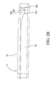
- FIGs. 2A and 2B are perspective diagrams of a portable electronic device in a closed state according to an embodiment of the invention.
- FIG. 3 is a perspective diagram of a portable electronic device in an open state
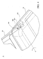
- FIG. 4 is a large view of portion A in FIG. 3 ;
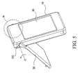
- FIG. 5 is a perspective diagram of a portable electronic device in an upright state
- FIG. 6 is a large view of portion B in FIG. 4 .
- portable electronic device such as a mobile phone or PDA, primarily comprises a main body 10 and a cover 20.
- the cover 20 comprises two extending portions 21 at opposite sides thereof.
- Each of the extending portions 21 has a pivot portion 201 formed on an inner surface thereof and pivotally connected to the main body 10, such that the cover 20 is rotatable with respect to the main body 10, as the arrows indicate in FIG. 2B .
- the main body 10 has a first hole 101 a second hole 102 disposed on a lateral surface thereof.
- a nub 202 on the inner surface of the cover 20 engages in the first hole 101 of the main body 10, as shown in FIG. 4 , thereby retaining the electronic device in an open state.
- the nub 202 engages in the second hole 102 to retain the electronic device in an upright state.
- the cover 20 When operating the electronic device or watching a display 30 on the electronic device, the cover 20 is unfolded and held in the first position or the second position, such that the electronic device is retained in the open state or the upright state for convenient usage. However, when the electronic device is not in use, the cover 20 is folded with respect to the main body 10 to cover and protect the display 30, such that the electronic device returns to the closed state as shown in FIGs. 2A and 2B .
- the cover 20 may comprise transparent or flexible plastic material.
- FIG. 4 is a large view of portion A in FIG. 3 .
- the cover 20 rotates around a central axis C of the pivot portion 20 to the first position, as shown in FIG. 4 , wherein the nub 202 on the inner surface of the cover 20 engages in the first hole 101 of the main body 10, thereby holding the cover 20 in the first position and retaining the electronic device in the open state.
- FIG. 6 is a large view of portion B in FIG. 5 .
- the electronic device is switched to an upright state ( FIG. 5 ), wherein the nub 202 of the cover 20 engages in the second hole 102 of the main body 10, as shown in FIG. 6 , thereby retaining the cover 20 in the second position.
- the main body 10 and the cover 20 form an inverted V-shaped structure to conveniently stand on a flat surface, such as a table, so that users can feel more comfortable when watching the display 30.
- the central axis C is substantially perpendicular to the lateral surface of the main body 10. Furthermore, when in the open state, the main body 10 and the cover 20 may have an angle of about 150°. When in the upright state, the main body 10 and the cover 20 may have an angle of about 300°. According to different mechanical and functional requirements, the main body 10 and the cover 20 may exhibit different angles by modifying positions and arrangement of the nub 202 and the first and second holes 101 and 102.
- the invention provides a portable electronic device primarily comprising a main body 10 and a rotatable cover 20.
- the cover 20 comprises at least an extending portion 21 with a nub 201 formed on an inner surface thereof.
- the main body 10 comprises a first hole 101 and a second hole 102 on a lateral surface thereof, corresponding to the nub 201.
- the electronic device can be alternatively switched to an open state or an upright state for convenient usage.
- the pivot portion 201 of the cover 20 may couple with a damper or resilient mechanism (such as torsion spring), thereby automatically impelling the cover 20 to the first or second position.
- a damper or resilient mechanism such as torsion spring
Landscapes
- Engineering & Computer Science (AREA)
- Computer Hardware Design (AREA)
- Theoretical Computer Science (AREA)
- General Engineering & Computer Science (AREA)
- Human Computer Interaction (AREA)
- Physics & Mathematics (AREA)
- General Physics & Mathematics (AREA)
- Signal Processing (AREA)
- Telephone Set Structure (AREA)
- Casings For Electric Apparatus (AREA)
Abstract
Description
- The invention relates in general to a portable electronic device and in particular to a portable electronic device with a positioning mechanism.
- Referring to
FIG. 1 , a conventional portable electronic device, such as a mobile phone or PDA, primarily comprises amain body 100 and acover 200 pivotally connected thereto. When using the portable electronic device, thecover 200 is unfolded as the arrow indicates inFIG. 1 . When the portable electronic device is not in use, thecover 200 is collapsed to protect adisplay 300 on themain body 100. Generally, the electronic device can be hand-held or lie on a table for manual operation, but it cannot stand in an upright position. - The invention provides a portable electronic device including a main body and a cover pivotally connected thereto. The main body comprises a first hole and a second hole formed on a lateral surface of the main body. When the cover rotates with respect to the main body to a first position, a nub of the cover engages in the first hole, such that the cover and the main body form a first angle. When the cover rotates with respect to the main body to a second position, the nub of the cover engages in the second positioning hole, such that the cover and the main body form a second angle.
- The invention can be more fully understood by reading the subsequent detailed description and examples with references made to the accompanying drawings, wherein:
-
FIG. 1 is a perspective diagram of a conventional portable electronic device; -
FIGs. 2A and2B are perspective diagrams of a portable electronic device in a closed state according to an embodiment of the invention; -
FIG. 3 is a perspective diagram of a portable electronic device in an open state; -
FIG. 4 is a large view of portion A inFIG. 3 ; -
FIG. 5 is a perspective diagram of a portable electronic device in an upright state; and -
FIG. 6 is a large view of portion B inFIG. 4 . - Referring to
FIGs. 2A and2B , portable electronic device according to an embodiment of the invention, such as a mobile phone or PDA, primarily comprises amain body 10 and acover 20. Thecover 20 comprises two extendingportions 21 at opposite sides thereof. Each of the extendingportions 21 has apivot portion 201 formed on an inner surface thereof and pivotally connected to themain body 10, such that thecover 20 is rotatable with respect to themain body 10, as the arrows indicate inFIG. 2B . - In this embodiment, the
main body 10 has a first hole 101 asecond hole 102 disposed on a lateral surface thereof. When thecover 20 is unfolded with respect to themain body 10 from a closed state (FIGs. 2A and2B ) to a first position (FIGs. 3 and4 ), anub 202 on the inner surface of thecover 20 engages in thefirst hole 101 of themain body 10, as shown inFIG. 4 , thereby retaining the electronic device in an open state. Referring toFIG. 5 and6 , when thecover 20 rotates over the first position to a second position, thenub 202 engages in thesecond hole 102 to retain the electronic device in an upright state. - When operating the electronic device or watching a
display 30 on the electronic device, thecover 20 is unfolded and held in the first position or the second position, such that the electronic device is retained in the open state or the upright state for convenient usage. However, when the electronic device is not in use, thecover 20 is folded with respect to themain body 10 to cover and protect thedisplay 30, such that the electronic device returns to the closed state as shown inFIGs. 2A and2B . In some embodiments, thecover 20 may comprise transparent or flexible plastic material. -
FIG. 4 is a large view of portion A inFIG. 3 . When the electronic device switches from the closed state to an open state, thecover 20 rotates around a central axis C of thepivot portion 20 to the first position, as shown inFIG. 4 , wherein thenub 202 on the inner surface of thecover 20 engages in thefirst hole 101 of themain body 10, thereby holding thecover 20 in the first position and retaining the electronic device in the open state. -
FIG. 6 is a large view of portion B inFIG. 5 . When the cover rotates around the central axis C to the second position, the electronic device is switched to an upright state (FIG. 5 ), wherein thenub 202 of thecover 20 engages in thesecond hole 102 of themain body 10, as shown inFIG. 6 , thereby retaining thecover 20 in the second position. When in the upright state, themain body 10 and thecover 20 form an inverted V-shaped structure to conveniently stand on a flat surface, such as a table, so that users can feel more comfortable when watching thedisplay 30. - In this embodiment, the central axis C is substantially perpendicular to the lateral surface of the
main body 10. Furthermore, when in the open state, themain body 10 and thecover 20 may have an angle of about 150°. When in the upright state, themain body 10 and thecover 20 may have an angle of about 300°. According to different mechanical and functional requirements, themain body 10 and thecover 20 may exhibit different angles by modifying positions and arrangement of thenub 202 and the first andsecond holes - The invention provides a portable electronic device primarily comprising a
main body 10 and arotatable cover 20. Thecover 20 comprises at least an extendingportion 21 with anub 201 formed on an inner surface thereof. Themain body 10 comprises afirst hole 101 and asecond hole 102 on a lateral surface thereof, corresponding to thenub 201. The electronic device can be alternatively switched to an open state or an upright state for convenient usage. In some embodiments, thepivot portion 201 of thecover 20 may couple with a damper or resilient mechanism (such as torsion spring), thereby automatically impelling thecover 20 to the first or second position. In conclusion, the portable electronic device of the invention can improve convenience of usage with a simplified mechanism and low production cost. - While the invention has been described by way of example and in terms of preferred embodiment, it is to be understood that the invention is not limited thereto. To the contrary, it is intended to cover various modifications and similar arrangements (as would be apparent to those skilled in the art). Therefore, the scope of the appended claims should be accorded the broadest interpretation to encompass all such modifications and similar arrangements.
Claims (12)
- A portable electronic device, characterized by comprising:a main body (10), comprising a lateral surface, a first hole (101) and a second hole (102), wherein the first and second holes (101, 102) are disposed on the lateral surface; anda cover (20), pivotally connecting the main body (10) and comprising a nub (202), wherein when the cover (20) rotates to a first position with respect to the main body (10), the nub is engaged in the first hole (101), such that the cover (20) and the main body (10) have a first angle,wherein when the cover (20) rotates to a second position with respect to the main body (10), the nub (202) is engaged in the second hole (102), such that the cover (20) and the main body (10) have a second angle.
- The portable electronic device as claimed in claim 1, characterized in that the first angle is substantially 150°.
- The portable electronic device as claimed in claim 1, characterized in that the second angle is substantially 300°.
- The portable electronic device as claimed in claim 1, characterized in that when the cover (20) rotates to the second position, the cover (20) and the main body (10) form an inverted V-shaped structure, such that the portable electronic device stands on a flat surface.
- The portable electronic device as claimed in claim 1, characterized in that the portable electronic device further comprises a display (30) concealed by the cover (20) when in a closed state.
- The portable electronic device as claimed in claim 1, characterized in that the cover (20) is transparent.
- The portable electronic device as claimed in claim 1, characterized in that the cover (20) is flexible.
- The portable electronic device as claimed in claim 1, characterized in that the cover (20) comprises plastic material.
- The portable electronic device as claimed in claim 1, characterized in that the cover (20) further comprises an extending portion (21) with the nub (202) formed on an inner surface thereof.
- The portable electronic device as claimed in claim 9, characterized in that the cover (20) further comprises a pivot portion (201) pivotally connected to the main body (10), and the pivot portion (201) has a central axis (C) substantially perpendicular to the lateral surface.
- The portable electronic device as claimed in claim 1, characterized in that the portable electronic device is a mobile phone.
- The portable electronic device as claimed in claim 1, characterized in that the portable electronic device is a PDA.
Applications Claiming Priority (1)
| Application Number | Priority Date | Filing Date | Title |
|---|---|---|---|
| TW96130124A TW200908852A (en) | 2007-08-15 | 2007-08-15 | Portable electronic devices |
Publications (1)
| Publication Number | Publication Date |
|---|---|
| EP2026541A1 true EP2026541A1 (en) | 2009-02-18 |
Family
ID=39944353
Family Applications (1)
| Application Number | Title | Priority Date | Filing Date |
|---|---|---|---|
| EP08014545A Withdrawn EP2026541A1 (en) | 2007-08-15 | 2008-08-14 | Portable electronic device |
Country Status (2)
| Country | Link |
|---|---|
| EP (1) | EP2026541A1 (en) |
| TW (1) | TW200908852A (en) |
Citations (5)
| Publication number | Priority date | Publication date | Assignee | Title |
|---|---|---|---|---|
| JPH10150480A (en) * | 1996-11-18 | 1998-06-02 | Nec Corp | Portable communication machine |
| WO1998025388A1 (en) * | 1996-12-06 | 1998-06-11 | Koninklijke Philips Electronics N.V. | Telephone |
| WO2000049731A1 (en) * | 1999-02-19 | 2000-08-24 | Bodycom, Inc. | Personal digital assistant with wireless telephone |
| US6754514B1 (en) * | 1999-04-16 | 2004-06-22 | Nec Corporation | Portable mobile radio telephone apparatus |
| US20050225667A1 (en) * | 2004-04-13 | 2005-10-13 | Elmo Company, Limited | Imaging apparatus |
-
2007
- 2007-08-15 TW TW96130124A patent/TW200908852A/en unknown
-
2008
- 2008-08-14 EP EP08014545A patent/EP2026541A1/en not_active Withdrawn
Patent Citations (5)
| Publication number | Priority date | Publication date | Assignee | Title |
|---|---|---|---|---|
| JPH10150480A (en) * | 1996-11-18 | 1998-06-02 | Nec Corp | Portable communication machine |
| WO1998025388A1 (en) * | 1996-12-06 | 1998-06-11 | Koninklijke Philips Electronics N.V. | Telephone |
| WO2000049731A1 (en) * | 1999-02-19 | 2000-08-24 | Bodycom, Inc. | Personal digital assistant with wireless telephone |
| US6754514B1 (en) * | 1999-04-16 | 2004-06-22 | Nec Corporation | Portable mobile radio telephone apparatus |
| US20050225667A1 (en) * | 2004-04-13 | 2005-10-13 | Elmo Company, Limited | Imaging apparatus |
Also Published As
| Publication number | Publication date |
|---|---|
| TW200908852A (en) | 2009-02-16 |
Similar Documents
| Publication | Publication Date | Title |
|---|---|---|
| KR200493314Y1 (en) | Mobile device and computer device stand | |
| US8248789B2 (en) | Electronic device | |
| US6819549B1 (en) | Hinged protective cover for portable electronic device | |
| US8948824B2 (en) | Electronic devices with clips | |
| US8339777B2 (en) | Portable electronic device with improved pivoting range | |
| US20250119486A1 (en) | Folding case with rotating side cover | |
| US20150282354A1 (en) | Multi viewing angle portable electronic device support | |
| US8602375B2 (en) | Portable and foldable support bracket | |
| US20210018961A1 (en) | Hinge device and foldable device having same | |
| JP2012227794A (en) | Finger hook for portable terminal and portable terminal | |
| US8644013B2 (en) | Movable hinge | |
| CN102905479B (en) | Foldable cellular electronic installation | |
| JP2022066795A (en) | Information device system and input apparatus | |
| KR20160063599A (en) | Finger support ring for portable terminal | |
| CN107450664B (en) | cover assembly | |
| CN102256462A (en) | Portable electronic system | |
| KR102272058B1 (en) | Case for handy terminal | |
| WO2009035242A2 (en) | Swing hinge for mobile phones | |
| CN113900528A (en) | Electronic equipment protective sleeve and electronic equipment assembly | |
| US8190218B2 (en) | Foldable handheld device | |
| KR102298206B1 (en) | Tablet holder | |
| KR102051589B1 (en) | Exterior cover with cradling | |
| CN103163942A (en) | Peripheral device | |
| KR20130001707U (en) | Stand assembly for mobile device | |
| CN2547073Y (en) | Portable electronic apparatus |
Legal Events
| Date | Code | Title | Description |
|---|---|---|---|
| PUAI | Public reference made under article 153(3) epc to a published international application that has entered the european phase |
Free format text: ORIGINAL CODE: 0009012 |
|
| AK | Designated contracting states |
Kind code of ref document: A1 Designated state(s): AT BE BG CH CY CZ DE DK EE ES FI FR GB GR HR HU IE IS IT LI LT LU LV MC MT NL NO PL PT RO SE SI SK TR |
|
| AX | Request for extension of the european patent |
Extension state: AL BA MK RS |
|
| 17P | Request for examination filed |
Effective date: 20090806 |
|
| AKX | Designation fees paid |
Designated state(s): DE FR GB |
|
| 17Q | First examination report despatched |
Effective date: 20161124 |
|
| STAA | Information on the status of an ep patent application or granted ep patent |
Free format text: STATUS: THE APPLICATION HAS BEEN WITHDRAWN |
|
| 18W | Application withdrawn |
Effective date: 20170120 |