EP2026375A2 - Electrical supply unit for plasma systems - Google Patents
Electrical supply unit for plasma systems Download PDFInfo
- Publication number
- EP2026375A2 EP2026375A2 EP08170182A EP08170182A EP2026375A2 EP 2026375 A2 EP2026375 A2 EP 2026375A2 EP 08170182 A EP08170182 A EP 08170182A EP 08170182 A EP08170182 A EP 08170182A EP 2026375 A2 EP2026375 A2 EP 2026375A2
- Authority
- EP
- European Patent Office
- Prior art keywords
- arcs
- plasma
- voltage
- supply unit
- electrical supply
- Prior art date
- Legal status (The legal status is an assumption and is not a legal conclusion. Google has not performed a legal analysis and makes no representation as to the accuracy of the status listed.)
- Granted
Links
Images


Classifications
-
- H—ELECTRICITY
- H01—ELECTRIC ELEMENTS
- H01J—ELECTRIC DISCHARGE TUBES OR DISCHARGE LAMPS
- H01J37/00—Discharge tubes with provision for introducing objects or material to be exposed to the discharge, e.g. for the purpose of examination or processing thereof
- H01J37/32—Gas-filled discharge tubes
- H01J37/32009—Arrangements for generation of plasma specially adapted for examination or treatment of objects, e.g. plasma sources
- H01J37/32018—Glow discharge
- H01J37/32027—DC powered
-
- H—ELECTRICITY
- H01—ELECTRIC ELEMENTS
- H01J—ELECTRIC DISCHARGE TUBES OR DISCHARGE LAMPS
- H01J2237/00—Discharge tubes exposing object to beam, e.g. for analysis treatment, etching, imaging
- H01J2237/02—Details
- H01J2237/0203—Protection arrangements
- H01J2237/0206—Extinguishing, preventing or controlling unwanted discharges
Definitions
- the invention relates to an electrical supply unit for plasma systems, such as plasma processing or coating devices, in which there may be the occurrence of arcs or breakdowns (arcs) in particular between the electrodes, according to the preamble of the independent claims.
- Plasma systems for which the generic electrical supply units are intended have a variety of applications and are used, for example, for sputtering of targets. In general, they have an electrical power in the order of about a few kW up to more than 100 kW.
- the applied to the electrodes operating voltage is typically in the order of 400 V. Of course, deviations are up or down - also depending on the application - possible.
- the invention has for its object to provide an electrical supply unit for plasma systems, in which the system reaches its full capacity as soon as possible after re-applying the operating voltage, and / or in the efficiency reduction by the occurrence of arcs or breakdowns, for example by the "prophylactic" switching off the operating voltage is as low as possible.
- the starting point is an electrical supply unit which has a direct voltage or direct current source whose output terminals are connected to the electrodes of the plasma system via at least one inductance and a circuit breaker and optionally a circuit for detecting arcs or breakdowns which occurs when a Arc or a punch the Switch is operated so that no electrical energy is applied to the electrodes.
- the invention consists in that the inductance (s) is in each case connected to a freewheeling diode (are), and that the switch is a series switch.
- the supply unit according to the invention operates as follows:
- the switch which switches the electric power applied to the electrodes opens the current flow between the DC voltage source and the electrodes when an arc is detected.
- the diodes which are reverse-connected with respect to the normal operating voltage, prevent opening of the circuit breaker, that the voltages on the inductors increase and at the same time cause the current in the inductors decreases only very slowly. If the circuit breaker is switched on again after a short time, typically about a few milliseconds, the current stored in the inductors is immediately available so that the system achieves its full power faster than in the prior art.
- the supply unit according to the invention thus has a current source characteristic when the circuit breaker is switched on again.
- the switch As a switch, of course, the most diverse circuit breakers can be used. However, in view of the high performance, it is preferable that the switch is an IGBT.
- the DC voltage source is a switching regulator power supply.
- a capacitor is connected between the terminals of the DC or DC power source. This capacitor is used to avoid voltage spikes caused by the lead inductances in the supply unit may occur. Furthermore, this capacitor is charged to the full open circuit voltage during the time in which the power switch is turned off, so that when switching on the circuit breaker, the full voltages for igniting the plasma is available.
- the supply unit according to the invention can be used for a variety of plasma systems, such as plasma systems, in which one electrode has at least one arranged in a plasma chamber cathode, and the other electrode is the housing of the plasma chamber.
- the supply unit according to the invention also has the particular advantage that it can also be used for plasma systems in which at least two separate cathodes are provided, each of which is connected via a series switch with the connected to a freewheeling diode inductance at the one terminal of the DC voltage source.
- Diode In one embodiment of the invention is between the electrode terminals and the electrode pairs a Diode switched. The function of this diode is explained below:
- the circuit breaker When the circuit breaker is opened, the voltage at the supply inductances polts around to the plasma chamber, so that voltage peaks would result without further circuit measures.
- the diode connected between the electrode terminals short-circuits this voltage so that the energy stored in the lead inductances is dissipated.
- a capacitor may be connected in series with the diode. Between cathode terminal and the connection point diode / capacitor then another series switch is connected.
- this circuit construction the energy resulting from the line inductance and the flowing current is reloaded as voltage into the capacitor when opening the circuit breaker. After a short delay, this voltage is applied to the electrodes via the further series switch, so that the arc is extinguished much faster than with a passive circuit.
- This Inversloossario can be in particular an (auxiliary) DC voltage source whose negative pole is connected to the anode and its positive pole via a diode connected in the forward direction to one terminal of another series switch.
- the circuit for detecting arcs except the circuit breaker also controls the other switch.
- a control unit which may in particular be part of the circuit for detecting arcs, may be provided, which "off prophylactically" with a fixed period removes and preferably switches over the voltage applied to the electrodes. If the voltage applied to the electrodes is regularly reversed for a short moment, arcs can be significantly reduced arcs are or can be erased already in its creation.
- the regular reversal of the voltage leads only to a very small reduction of the sputtering power, provided that the period of time during which the voltage applied to the electrodes is switched substantially shorter than the time period during which a plasma operation is performed. Furthermore, the period during which the voltage is switched, of course, must be so short that the current in the circuit "inductance / recovery diode" is stored.
- the frequency with which the control unit switches off or switches the voltage applied to the electrodes can be up to 100 kHz.
- control unit in the manner of an adaptive control adjusts the duty cycle of the voltage so that "just "no arc or breakdown occurs.
- a control or regulating unit is provided, which in the occurrence of an arc or breakdown this by switching off the the electrodes applied voltage or switching to an Inversschreib for a certain period of time (off duration) clears, and that- the control unit after the occurrence of at least one arc or the breakdown reduces the duty cycle of the voltage causing a plasma operation.
- control unit reduces the duty cycle to a period of time which is smaller than the current time interval between two successive arcs or breakdowns. Since the operating parameters of a plant can change during a processing operation, it is furthermore preferred if the control unit also increases the duty cycle:
- control unit increases the duty cycle when no arc or breakdown or only a certain number of arcs or breakdowns has occurred over a certain period or over a certain number of switch-on.
- the control unit can extend the duty cycle to CW operation.
- control unit reduces the duty cycle only if a certain number of arcs or breakdowns has occurred during a certain time.
- control or regulating unit switches on the voltage applied to the electrodes either permanently or for a specific switch-on duration (predeterminable before the start of the process), then switches off or preferably switches over for a specific switch-off duration, and then the voltage turns back on, and reduces the on-time of the voltage when arcs or breakdowns.
- the initial values of the switch-on duration and the switch-off duration and / or the number of arcs and the time unit in which this number occurs are adjustable.
- the duty cycle is associated with the frequency of occurrence of arcs or breakdowns via a variable characteristic curve, which may be dependent on further process parameters.
- control unit optimizes the switch-off duration or the switchover duration.
- the off or switching time is set “just” so long that the arc or breakdown (Arc) is "sustainably" deleted.
- Fig. 1 shows a first embodiment of the invention.
- the power supply unit has a switching regulator power supply 1, which supplies a direct current voltage of approximately 400 V, for example (ie without limiting the generality).
- the negative output terminal A- of the power supply 1 is connected via an inductor L1 and a circuit breaker designed as a series switch V3 with a cathode K in a plasma chamber 2, whose housing is grounded.
- the series switch 1 is an IGBT in the embodiment shown.
- the positive output terminal A + of the power supply 1 is connected via an inductance L2 to the housing of the plasma chamber 2. This is symbolically denoted by GND.
- diodes V1 and V2 are switched according to the invention, which are polarized such that they lock during plasma operation.
- a capacitor C1 is connected between the output terminals A- and A +.
- a diode V4 is connected, which is polarized in the reverse direction during plasma operation.
- the power switch V3 Upon detection of an arc, the power switch V3 is opened by the circuit 3, so that the flow of current between the power supply 1 and the electrodes of the plasma chamber 2 is interrupted.
- the circuit breaker When the circuit breaker is opened, the voltage at the supply inductances to the plasma chamber 2 poles; In order to avoid that this leads to voltage peaks, the electrodes are short-circuited via the diode V4 and the energy stored in the lead inductances is dissipated.
- the diodes V1 and V2 prevent the voltages at the inductors L1 and L2 from rising when the circuit breaker is opened, and at the same time cause the current in the inductors to decrease only very slowly.
- the inductors L1 and L2 can also be magnetically coupled.
- the capacitor C1 serves to avoid voltage spikes which may occur due to the lead inductances.
- Fig. 1 shown electrical supply unit with reference to Fig. 2 in which a voltage / time diagram is shown, are described in more detail:
- the voltage U breaks down due to an arc on the voltage UARC typical for an arc or breakdown.
- the switch V3 is opened and the power supply is interrupted.
- the switch V3 is closed again, the voltage rises to the ignition voltage UZÜND and breaks back to the burning voltage UPLASMA.
- the generator output current is stored at the time of switching off, so that when restarting the original operating state is reached very quickly again.
- Fig. 3 shows a modification of the in Fig. 1 shown embodiment.
- Fig. 3 shows a modification of the in Fig. 1 shown embodiment.
- the same parts as in Fig. 1 provided with the same reference numerals, so that dispenses with a new idea.
- a capacitor C2 is connected in series with the diode V4.
- a further series switch V5 is connected, which is also driven by the circuit 3 via the output terminal gate2.
- an inversion voltage source can optionally be provided which has an (auxiliary) DC voltage source U1, which typically supplies a voltage of about 30 V.
- the negative pole of the DC voltage source U1 is connected to the anode, while the positive pole of the DC voltage source U1 is connected via a diode connected in the forward direction V6 to one terminal of another series switch V5.
- oxidized targets can be freedputtertert.
- Fig. 5 schematically shows the voltage curve for this modification of in Fig. 3 shown embodiment.
- the pulse frequencies can be up to 100 kHz depending on the circuit breaker used.
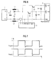
- Fig. 6 shows the circuit of a third embodiment of the invention, in which two cathodes K1 and K2 are arranged in the plasma chamber 2, which each own power switches V3 and V5 and diodes V4 and V6 are assigned.
- the two cathodes operate in parallel operation. If the two switches are switched on alternately, the effective power of the cathodes can be regulated by varying the switch-on times. Switching frequencies up to several kHz are possible.
- Fig. 7 shows a voltage / time diagram in which the alternating switching of the two switches is shown schematically.
- more than two cathodes can be used.
- Fig. 8 shows a fourth embodiment of the invention, in which the reduction in performance, resulting in the procedure according to Fig. 5 by the prophylactic switching of the voltage with a fixed, predetermined frequency results, is significantly reduced:
- the circuit 3 is supplemented by an adaptive control unit 4 with a starting value input unit 5.
- the duty cycle of the voltage applied to the electrodes is not fixed.
- the highest possible duty cycle is set by the adaptive control unit 4 in order to avoid the plasma process in a plasma system 6 by unnecessary blanking - as in Fig. 5 and 7 to interrupt.
- the duty cycle will be shortened after erasing the arc. This reduces the probability of the occurrence of a repeated arc. If an arc continues to occur despite the shortened duty cycle, the duty cycle is further reduced until a stable, arc-free operation is possible. Accordingly, the duty cycle is extended if no arcs have occurred over a certain period of time. The duty cycle is then extended until again arcs occur in the process. The extension of the duty cycle can go so far that the system in the "continuous operation" (CW operation) is driven.
- the switch-on time and the arc frequency can be linked or correlated with one another via a variable characteristic curve of the adaptive control unit, which can depend on further process parameters - process gases, target and sputter materials, etc.
- Fig. 9 shows qualitatively a characteristic which correlates the arc frequency (1 / s) plotted on the abscissa with the on-ordinate applied on-time (s).
- corresponding characteristics depend not only on several parameters, but also on the geometry of the plasma system, the process materials and so on.
- the characteristic curves are preferably determined empirically and / or adjusted adaptively by the control unit 4, which may have, for example, a microprocessor.
- Certain values for the switch-on duration, as well as the switch-off or switch-off duration at the beginning of the plasma operation, which are recognized as advantageous, can be predefined via the start value specification unit 5, or certain already determined characteristic curve can be selected.
- the parameters of the arc management are optimally adapted to the process parameters.
- the supply unit according to the invention can be used for all applications known from the introductory literature.
- the various characteristics of the embodiments can be combined with each other: Thus, it is possible to combine the pulse mode or the adaptive control, the active arc extinction and the switching between two or more cathodes partially or completely or switch between the individual operating modes described.
Abstract
Description
Die Erfindung bezieht sich auf eine elektrische Versorgungseinheit für Plasmaanlagen, wie Plasma-Bearbeitungs- bzw. Beschichtungsvorrichtungen, bei denen es zum Auftreten von Lichtbögen bzw. Durchschlägen (Arcs) insbesondere zwischen den Elektroden kommen kann, gemäß dem Oberbegriff der unabhängigen Patentansprüche.The invention relates to an electrical supply unit for plasma systems, such as plasma processing or coating devices, in which there may be the occurrence of arcs or breakdowns (arcs) in particular between the electrodes, according to the preamble of the independent claims.
Plasmaanlagen, für die die gattungsgemäßen elektrischen Versorgungseinheiten bestimmt sind, haben eine Vielzahl von Anwendungsmöglichkeiten und werden beispielsweise zum Besputtern von Targets eingesetzt. In der Regel haben sie eine elektrische Leistung in der Größenordnung von ca. einigen kW bis zu mehr als 100 kW. Die an die Elektroden angelegte Betriebsspannung liegt dabei typischerweise in der Größenordnung von 400 V. Selbstverständlich sind dabei Abweichungen nach oben oder unten - auch in Abhängigkeit von der Anwendung - möglich.Plasma systems for which the generic electrical supply units are intended have a variety of applications and are used, for example, for sputtering of targets. In general, they have an electrical power in the order of about a few kW up to more than 100 kW. The applied to the electrodes operating voltage is typically in the order of 400 V. Of course, deviations are up or down - also depending on the application - possible.
Insbesondere beim sogenannten "reaktiven" Sputtern, das zum Beispiel zur Herstellung von Oxid- oder Nitrid-Filmen verwendet wird, oder bei der Verwendung reaktiver Gase ergeben sich Probleme durch das Auftreten von Durchschlägen und/oder die Bildung isolierender Schichten auf dem leitenden Target, durch die sich parasitäre Kondensatoren ausbilden können.In particular, in the so-called "reactive" sputtering, which is used for example for the production of oxide or nitride films, or in the use of reactive gases, problems arise due to the occurrence of breakdowns and / or the formation of insulating layers on the conductive target which can form parasitic capacitors.
Es sind die verschiedensten passiven und aktiven Schaltungen bekannt, die zum Löschen von Lichtbögen dienen, die sich aufgrund von Durchschlägen gebildet haben. Allen diesen Schaltungen ist gemeinsam, daß für einen bestimmten Zeitraum die an die Elektroden angelegte Spannung abgeschaltet wird. Nur exemplarisch wird hierzu auf die
Die
Nachteilig bei den aus diesen Druckschriften bekannten Schaltungen ist, daß nach dem Wiedereinschalten der Betriebsspannung das System eine vergleichsweise lange Zeit benötigt, um wieder mit "voller Leistung sputtern" oder das Target in anderer Weise bearbeiten zu können.A disadvantage of the circuits known from these documents is that after the reconnection of the operating voltage, the system requires a comparatively long time to sputter again with "full power" or edit the target in other ways.
Entsprechendes gilt, wenn das System in einem sogenannten asymmetrischen Pulsbetrieb betrieben wird, um die Bildung von isolierenden Schichten auf dem Target zu verhindern.The same applies if the system is operated in a so-called asymmetric pulse mode in order to prevent the formation of insulating layers on the target.
Weiterhin ist es bekannt, die an die Elektroden angelegte Spannung periodisch - unabhängig davon ob ein Durchschlag oder ein Lichtbogen auftritt - für einen kurzen Zeitraum abzuschalten. Bei dieser Vorgehensweise muß die Einschaltdauer so gewählt werden, daß während der Zeit, während der die Spannung angelegt ist, kein Durchschlag bzw. kein Lichtbogen auftritt. Damit kann zwar das Auftreten von Durchschlägen bzw. Lichtbögen verhindert werden, durch das periodische Abschalten und das anschließende Wiederanlegen der Spannung wird die Effizienz der Anlage jedoch deutlich reduziert.Furthermore, it is known that the voltage applied to the electrodes periodically - regardless of whether a breakdown or an arc occurs - turn off for a short period of time. In this procedure the duty cycle must be chosen so that during the time during which the voltage is applied, no breakdown or no arc occurs. Although this prevents the occurrence of breakdowns or arcs, the periodic shutdown and the subsequent re-application of the voltage significantly reduces the efficiency of the system.
Der Erfindung liegt die Aufgabe zugrunde, eine elektrische Versorgungseinheit für Plasmaanlagen anzugeben, bei der nach dem Wiederanlegen der Betriebsspannung an die Elektroden das System möglichst schnell seine volle Leistung erreicht, und/oder bei der die Effizienzverringerung durch das Auftreten von Lichtbögen bzw. Durchschlägen beispielsweise durch das "prophylaktische" Abschalten der Betriebsspannung möglichst gering ist.The invention has for its object to provide an electrical supply unit for plasma systems, in which the system reaches its full capacity as soon as possible after re-applying the operating voltage, and / or in the efficiency reduction by the occurrence of arcs or breakdowns, for example by the "prophylactic" switching off the operating voltage is as low as possible.
Erfindungsgemäße Lösungen dieser Aufgabe sind in den Patentansprüchen 1 bzw. 18 angegeben. Weiterbildungen der Erfindung sind Gegenstand der abhängigen Ansprüche.Inventive solutions to this problem are specified in the
Erfindungsgemäß wird von einer elektrischen Versorgungseinheit ausgegangen, die eine Gleichspannungs- bzw. Gleichstromquelle, deren Ausgangsanschlüsse über wenigstens eine Induktivität und einen Leistungsschalter mit den Elektroden der Plasmaanlage verbunden sind, und gegebenenfalls eine Schaltung zum Erkennen von Lichtbögen bzw. Durchschlägen aufweist, die beim Auftreten eines Lichtbogens bzw. eines Durchschlags den Schalter derart betätigt, daß keine elektrische Energie mehr an die Elektroden angelegt wird.According to the invention, the starting point is an electrical supply unit which has a direct voltage or direct current source whose output terminals are connected to the electrodes of the plasma system via at least one inductance and a circuit breaker and optionally a circuit for detecting arcs or breakdowns which occurs when a Arc or a punch the Switch is operated so that no electrical energy is applied to the electrodes.
Ausgehend von einer derartigen, bekannten Versorgungseinheit besteht die Erfindung darin, daß die Induktivität(en) jeweils mit einer Freilaufdiode beschaltet ist (sind), und daß der Schalter ein Serienschalter ist.Starting from such a known supply unit, the invention consists in that the inductance (s) is in each case connected to a freewheeling diode (are), and that the switch is a series switch.
Aufgrund dieser Ausbildung arbeitet die erfindungsgemäße Versorgungseinheit wie folgt:Due to this design, the supply unit according to the invention operates as follows:
Der Schalter, der die an die Elektroden angelegte elektrische Leistung schaltet (im folgenden auch als Leistungsschalter bezeichnet), öffnet beim Erkennen eines Lichtbogens den Stromfluß zwischen der Gleichspannungsquelle und den Elektroden. Die Dioden, die bezogen auf die normale Betriebsspannung in Sperrrichtung geschaltet sind, verhindern beim Öffnen des Leistungsschalters, daß die Spannungen an den Induktivitäten ansteigen und bewirken gleichzeitig, daß der Strom in den Induktivitäten nur sehr langsam abnimmt. Wird der Leistungsschalter bereits nach kurzer Zeit - typisch sind etwa einige Millisekunden - wieder eingeschaltet, so steht der in den Induktivitäten gespeicherte Strom sofort zur Verfügung, so daß das System schneller als beim Stand der Technik seine volle Leistung erreicht. Die erfindungsgemäße Versorgungseinheit hat damit beim Wiedereinschalten des Leistungsschalters eine Stromquellencharakteristik.The switch which switches the electric power applied to the electrodes (hereinafter also referred to as a power switch) opens the current flow between the DC voltage source and the electrodes when an arc is detected. The diodes, which are reverse-connected with respect to the normal operating voltage, prevent opening of the circuit breaker, that the voltages on the inductors increase and at the same time cause the current in the inductors decreases only very slowly. If the circuit breaker is switched on again after a short time, typically about a few milliseconds, the current stored in the inductors is immediately available so that the system achieves its full power faster than in the prior art. The supply unit according to the invention thus has a current source characteristic when the circuit breaker is switched on again.
Damit sind bei der erfindungsgemäßen elektrischen Versorgungseinheit die Einbußen in der Leistung aufgrund des Abschaltens der Betriebsspannung zur Löschung von Lichtbögen wesentlich geringer als beim Stand der Technik.Thus, in the electrical supply unit according to the invention, the losses in performance due switching off the operating voltage to extinguish arcs substantially lower than in the prior art.
Diese erfindungsgemäße - im Anspruch 1 angegebene - Grundschaltung kann unter verschiedenen Aspekten, die auch miteinander kombiniert werden können, erweitert werden:This invention - specified in claim 1 - basic circuit can be extended under various aspects, which can also be combined with each other:
Insbesondere ist es möglich, in jeder Leitung, die einen Anschluß der Gleichspannungs- bzw. Gleichstromquelle mit der jeweils zugeordneten Elektrode verbindet, eine Induktivität mit einer zugeordneten Freilaufdiode vorzusehen. Hierdurch erhält man einen besonders symmetrischen Schaltungsaufbau. Es ist jedoch möglich, nur eine Induktivität zu verwenden; in diesem Falle ist auch nur eine Freilaufdiode erforderlich.In particular, it is possible to provide an inductance with an associated freewheeling diode in each line which connects one terminal of the DC voltage or DC power source to the respective associated electrode. This gives a particularly symmetrical circuit structure. However, it is possible to use only one inductor; In this case, only one free-wheeling diode is required.
Als Schalter können selbstverständlich die unterschiedlichsten Leistungsschalter verwendet werden. Im Hinblick auf die hohe Leistung ist es jedoch bevorzugt, wenn der Schalter ein IGBT ist.As a switch, of course, the most diverse circuit breakers can be used. However, in view of the high performance, it is preferable that the switch is an IGBT.
Auch als Netzteil können die unterschiedlichsten Netzteile eingesetzt werden, ebenfalls im Hinblick auf die hohe Leistung ist es jedoch bevorzugt, wenn die Gleichspannungsquelle ein Schaltregler-Netzteil ist.As a power supply, a variety of power supplies can be used, also in view of the high performance, it is preferred if the DC voltage source is a switching regulator power supply.
In diese Falle ist es von Vorteil, wenn zwischen die Anschlüsse der Gleichspannung- bzw. Gleichstromquelle ein Kondensator geschaltet ist. Dieser Kondensator dient zur Vermeidung von Spannungsspitzen, die durch die Zuleitungsinduktivitäten in der Versorgungseinheit auftreten können. Weiterhin wird dieser Kondensator in der Zeit, in der der Leistungsschalter abgeschaltet ist, auf die volle Leerlaufspannung aufgeladen, so daß beim Durchschalten des Leistungsschalters die volle Spannungen zum Zünden des Plasmas zur Verfügung steht.In this case, it is advantageous if a capacitor is connected between the terminals of the DC or DC power source. This capacitor is used to avoid voltage spikes caused by the lead inductances in the supply unit may occur. Furthermore, this capacitor is charged to the full open circuit voltage during the time in which the power switch is turned off, so that when switching on the circuit breaker, the full voltages for igniting the plasma is available.
Die erfindungsgemäße Versorgungseinheit läßt sich für die verschiedensten Plasmaanlagen einsetzen, wie beispielsweise Plasmaanlagen, bei denen die eine Elektrode wenigstens eine in einer Plasmakammer angeordnete Kathode aufweist, und die andere Elektrode das Gehäuse der Plasmakammer ist. Die erfindungsgemäße Versorgungseinheit hat darüberhinaus den besonderen Vorteil, daß es auch für Plasmaanlagen verwendbar ist, bei denen wenigstens zwei voneinander getrennte Kathoden vorgesehen sind, von denen jede über einen Serienschalter mit der mit einer Freilaufdiode beschalteten Induktivität an dem einen Anschluß der Gleichspannungsquelle verbunden ist.The supply unit according to the invention can be used for a variety of plasma systems, such as plasma systems, in which one electrode has at least one arranged in a plasma chamber cathode, and the other electrode is the housing of the plasma chamber. The supply unit according to the invention also has the particular advantage that it can also be used for plasma systems in which at least two separate cathodes are provided, each of which is connected via a series switch with the connected to a freewheeling diode inductance at the one terminal of the DC voltage source.
Bei derartigen Systemen kann beispielsweise zwischen den Kathoden alternierend umgeschaltet werden. Dies hat den Vorteil, daß Lichtbögen, die an der einen Kathode "im Entstehen" sind, zuverlässig in dem vergleichsweise langen Zeitraum gelöscht werden, während dem auf die andere Kathode umgeschaltet wird. Selbstverständlich ist es aber auch möglich, gleichzeitig von mehreren Kathoden zu sputtern.In such systems, for example, can be switched alternately between the cathodes. This has the advantage that arcs "onset" at one cathode are reliably erased in the comparatively long period of time during which it is switched to the other cathode. Of course, it is also possible to sputter from several cathodes simultaneously.
Bei einer Weiterbildung der Erfindung ist zwischen die Elektrodenanschlüsse bzw. die Elektrodenpaare eine Diode geschaltet. Die Funktion dieser Diode wird im folgenden erläutert:In one embodiment of the invention is between the electrode terminals and the electrode pairs a Diode switched. The function of this diode is explained below:
Beim Öffnen des Leistungsschalters polt die Spannung an den Zuleitungsinduktivitäten zur Plasmakammer um, so daß sich ohne weitere Schaltungsmaßnahmen Spannungsspitzen ergeben würden. Die zwischen die Elektrodenanschlüsse geschaltete Diode schließt diese Spannung kurz, so daß die in den Zuleitungsinduktivitäten gespeicherte Energie abgebaut wird.When the circuit breaker is opened, the voltage at the supply inductances polts around to the plasma chamber, so that voltage peaks would result without further circuit measures. The diode connected between the electrode terminals short-circuits this voltage so that the energy stored in the lead inductances is dissipated.
Weiterhin ist es möglich, ein LC-Glied parallel zu der Diode zu schalten, das als passives Element die Löschung des Lichtbogens unterstützt.Furthermore, it is possible to connect an LC element in parallel to the diode, which supports the erasure of the arc as a passive element.
Besonders bevorzugt ist es jedoch, wenn die Löschung des Lichtbogens durch aktive Schaltungselemente unterstützt wird:However, it is particularly preferred if the extinguishment of the arc is supported by active circuit elements:
Hierzu kann in Reihe mit der Diode ein Kondensator geschaltet sein. Zwischen Kathodenanschluß und den Verbindungspunkt Diode/Kondensator ist dann ein weiterer Serienschalter geschaltet. Durch diesen Schaltungsaufbau wird die sich aus der Leitungsinduktivität und dem fließenden Strom ergebende Energie beim Öffnen des Leistungsschalters als Spannung in den Kondensator umgeladen. Nach einer kurzen Verzögerung wird diese Spannung über den weiteren Serienschalter an die Elektroden angelegt, so daß der Lichtbogen wesentlich schneller als bei einer passiven Schaltung gelöscht wird.For this purpose, a capacitor may be connected in series with the diode. Between cathode terminal and the connection point diode / capacitor then another series switch is connected. By this circuit construction, the energy resulting from the line inductance and the flowing current is reloaded as voltage into the capacitor when opening the circuit breaker. After a short delay, this voltage is applied to the electrodes via the further series switch, so that the arc is extinguished much faster than with a passive circuit.
Um auch bei kleinen Leitungsinduktivitäten oder kleinen Strömen eine entsprechend große invertierte Spannung zum Löschen zu erhalten, kann ferner eine Inversspannungsquelle vorgesehen werden.In order to obtain a correspondingly large inverted voltage for erasing even in the case of small line inductances or small currents, it is furthermore possible to provide an inverse voltage source.
Diese Inversspannungsquelle kann insbesondere eine (Hilfs)-Gleichspannungsquelle sein, deren Minuspol mit der Anode und deren Pluspol über eine in Vorwärtsrichtung geschaltete Diode mit dem einen Anschluß des weiteren Serienschalters verbunden ist.This Inversspannungsquelle can be in particular an (auxiliary) DC voltage source whose negative pole is connected to the anode and its positive pole via a diode connected in the forward direction to one terminal of another series switch.
In jedem Falle ist es bevorzugt, wenn die Schaltung zum Erkennen von Lichtbögen außer dem Leistungsschalter auch den weiteren Schalter ansteuert.In any case, it is preferred that the circuit for detecting arcs except the circuit breaker also controls the other switch.
Die Schaltung zum Erkennen von Lichtbögen kann dabei wenigstens eines der folgenden Kriterien auswerten:
- Spannungseinbruch,
- Überschreiten der Maximum-Spannungsgrenze,
- Unterschreiten der Minimum-Spannungsgrenze
- Schneller Stromanstieg,
- Überschreiten der Maximum-Stromgrenze.
- Voltage dip,
- Exceeding the maximum voltage limit,
- Below the minimum voltage limit
- Fast current increase,
- Exceeding the maximum current limit.
Weiterhin kann in an sich bekannter Weise eine Steuereinheit, die insbesondere Bestandteil der Schaltung zum Erkennen von Lichtbögen sein kann, vorgesehen sein, die "prophylaktisch" mit einer festen Periode die an die Elektroden angelegte Spannung ab- und bevorzugt umschaltet. Wird die an die Elektroden angelegte Spannung regelmäßig für einen kurzen Moment umgepolt, so kann die Entstehung von Lichtbögen wesentlich verringert werden bzw. können Lichtbögen schon in der Entstehung wieder gelöscht werden.Furthermore, in a manner known per se, a control unit, which may in particular be part of the circuit for detecting arcs, may be provided, which "off prophylactically" with a fixed period removes and preferably switches over the voltage applied to the electrodes. If the voltage applied to the electrodes is regularly reversed for a short moment, arcs can be significantly reduced arcs are or can be erased already in its creation.
Aufgrund der erfindungsgemäßen Ausbildung, die nach dem Wiederanschalten zu einem schnellen Erreichen der Leistung führt, führt das regelmäßige Umpolen der Spannung nur zu einer sehr geringen Reduzierung der Sputterleistung, sofern die Zeitdauer, während der die an die Elektroden angelegte Spannung umgeschaltet wird, wesentlich kürzer als die Zeitdauer ist, während der ein Plasmabetrieb ausgeführt wird. Weiterhin muß die Zeitdauer, während der die Spannung umgeschaltet wird, natürlich auch so kurz sein, daß der Strom in dem Kreis "Induktivität/Freilaufdiode" gespeichert wird.Due to the inventive design, which leads after switching on again to a rapid achievement of the power, the regular reversal of the voltage leads only to a very small reduction of the sputtering power, provided that the period of time during which the voltage applied to the electrodes is switched substantially shorter than the time period during which a plasma operation is performed. Furthermore, the period during which the voltage is switched, of course, must be so short that the current in the circuit "inductance / recovery diode" is stored.
Die Frequenz, mit der die Steuereinheit die an die Elektroden angelegte Spannung ab- bzw. umschaltet, kann dabei bis zu 100 kHz betragen.The frequency with which the control unit switches off or switches the voltage applied to the electrodes can be up to 100 kHz.
Anstelle einer periodischen prophylaktischen Umschaltung mit einer festen Periode, die unabhängig von den Prozeßparametern und der hiervon abhängigen Häufigkeit von Lichtbögen bzw. Durchschlägen ist, ist es jedoch bevorzugt, wenn die Steuereinheit in Art einer adaptiven Regelung die Einschaltdauer der Spannung so einstellt, daß "gerade" kein Lichtbogen bzw. Durchschlag auftritt. Bei dieser weiteren Lösung der erfindungsgemäß gestellten Aufgabe, die auch zusätzlich zu der Lösung gemäß Anspruch 1 verwendet werden kann, ist es von Vorteil, wenn eine Steuer- bzw. Regeleinheit vorgesehen ist, die beim Auftreten eines Lichtbogens bzw. Durchschlags diesen durch Abschalten der an die Elektroden angelegten Spannung oder Umschalten auf eine Inversspannung für eine bestimmte Zeitdauer (Ausschaltdauer) löscht, und daß- die Steuer- bzw. Regeleinheit nach dem Auftreten wenigstens eines Lichtbogens bzw. Durchschlags die Einschaltdauer der einen Plasmabetrieb hervorrufenden Spannung verringert.Instead of a periodic prophylactic switching with a fixed period, which is independent of the process parameters and the dependent frequency of arcs, however, it is preferred if the control unit in the manner of an adaptive control adjusts the duty cycle of the voltage so that "just "no arc or breakdown occurs. In this further solution of the invention according to the object, which can also be used in addition to the solution according to
Dabei ist es von besonderem Vorteil, wenn die Steuer- bzw. Regeleinheit die Einschaltdauer auf eine Zeitdauer verringert, die kleiner als der aktuelle Zeitabstand zwischen zwei nacheinander auftretenden Lichtbögen bzw. Durchschlägen ist. Da sich die Betriebsparameter einer Anlage während eines Bearbeitungsvorgangs ändern können, ist es weiterhin bevorzugt, wenn die Steuer- bzw. Regeleinheit die Einschaltdauer auch vergrößert:It is particularly advantageous if the control unit reduces the duty cycle to a period of time which is smaller than the current time interval between two successive arcs or breakdowns. Since the operating parameters of a plant can change during a processing operation, it is furthermore preferred if the control unit also increases the duty cycle:
Hierzu ist es beispielsweise möglich, daß die Steuer- und Regeleinheit die Einschaltdauer vergrößert, wenn über einen bestimmten Zeitraum bzw. über eine bestimmte Zahl von Einschaltperioden kein Lichtbogen bzw. Durchschlag oder nur eine bestimmte Zahl von Lichtbögen bzw. Durchschlägen aufgetreten ist. Die Steuer- und Regeleinheit kann die Einschaltdauer dabei bis zum CW-Betrieb verlängern.For this purpose, it is possible, for example, that the control unit increases the duty cycle when no arc or breakdown or only a certain number of arcs or breakdowns has occurred over a certain period or over a certain number of switch-on. The control unit can extend the duty cycle to CW operation.
Um das zufällige Auftreten von Arcs bei der adaptiven Regelung nicht so stark zu gewichten, ist es ferner bevorzugt, wenn die Steuer- bzw. Regeleinheit die Einschaltdauer nur dann verringert, wenn während einer bestimmten Zeit eine gewisse Zahl von Lichtbögen bzw. Durchschlägen aufgetreten ist.In order not to weight the random occurrence of arcs in the adaptive control so strong, it is further preferred if the control unit reduces the duty cycle only if a certain number of arcs or breakdowns has occurred during a certain time.
Weiterhin ist es bevorzugt, wenn die Steuer- bzw. Regeleinheit beim Beginn des Plasmabetriebs die an die Elektroden angelegte Spannung entweder dauernd oder für eine bestimmte (vor Beginn des Prozesses vorgebbare) Einschaltdauer einschaltet, dann für eine bestimmte Ausschaltdauer ab- oder bevorzugt umschaltet, und sodann die Spannung wieder einschaltet, und beim Auftreten von Lichtbögen bzw. Durchschlägen die Einschaltdauer der Spannung verringert.Furthermore, it is preferred if, at the beginning of the plasma operation, the control or regulating unit switches on the voltage applied to the electrodes either permanently or for a specific switch-on duration (predeterminable before the start of the process), then switches off or preferably switches over for a specific switch-off duration, and then the voltage turns back on, and reduces the on-time of the voltage when arcs or breakdowns.
Um die erfindungsgemäße Versorgungseinheit an die unterschiedlichsten Bearbeitungs- bzw. Aufbringvorgänge anpassen zu können, ist es ferner von Vorteil, wenn die anfänglichen Werte der Einschaltdauer und der Ausschaltdauer und/oder die Zahl von Lichtbögen bzw. Durchschlägen sowie die Zeiteinheit, in denen diese Zahl auftritt, einstellbar sind.In order to be able to adapt the supply unit according to the invention to the most varied of machining or application processes, it is also advantageous if the initial values of the switch-on duration and the switch-off duration and / or the number of arcs and the time unit in which this number occurs , are adjustable.
In jedem Falle ist es ferner von Vorteil, wenn die Einschaltdauer mit der Häufigkeit des Auftretens von Lichtbögen bzw. Durchschlägen über eine variable Kennlinie verknüpft ist, die von weiteren Prozeßparametern abhängig sein kann.In any case, it is also advantageous if the duty cycle is associated with the frequency of occurrence of arcs or breakdowns via a variable characteristic curve, which may be dependent on further process parameters.
Um die Reduzierung der Leistung der Plasmaanlage so gering wie möglich zu halten, ist es ferner von Vorteil, wenn die Steuer- bzw. Regeleinheit die Ausschaltdauer bzw. die Umschaltdauer optimiert. Die Aus- bzw. Umschaltdauer wird dabei "gerade" so lang eingestellt, daß der Lichtbogen bzw. Durchschlag (Arc) "nachhaltig" gelöscht wird.In order to keep the reduction of the power of the plasma system as low as possible, it is also advantageous if the control unit optimizes the switch-off duration or the switchover duration. The off or switching time is set "just" so long that the arc or breakdown (Arc) is "sustainably" deleted.
Die Erfindung wird nachstehend unter Bezugnahme auf die Zeichnung näher beschrieben, in der zeigen:
- Fig. 1
- die Schaltung eines ersten Ausführungsbeispiels der Erfindung,
- Fig. 2
- ein Spannungs/Zeit-Diagramm zur Erläuterung der Funktionsweise der in
Fig. 1 gezeigten Schaltung, - Fig. 3
- die Schaltung eines zweiten Ausführungsbeispiels der Erfindung,
- Fig. 4
- ein Spannungs/Zeit-Diagramm zur Erläuterung der Funktionsweise der in
Fig. 3 gezeigten Schaltung, - Fig. 5
- ein Spannungs/Zeit-Diagramm zur Erläuterung der Funktionsweise einer Modifikation der in
Fig. 3 gezeigten Schaltung, - Fig. 6
- die Schaltung eines dritten Ausführungsbeispiels der Erfindung,
- Fig. 7
- ein Spannungs/Zeit-Diagramm zur Erläuterung der Funktionsweise des dritten Ausführungsbeispiels, und
- Fig. 8
- ein Blockschaltbild eines vierten Ausführungsbeispiels, und
- Fig. 9
- eine Darstellung zur Erläuterung der Funktionsweise des vierten Ausführungsbeispiels.
- Fig. 1
- the circuit of a first embodiment of the invention,
- Fig. 2
- a voltage / time diagram explaining the operation of in
Fig. 1 shown circuit, - Fig. 3
- the circuit of a second embodiment of the invention,
- Fig. 4
- a voltage / time diagram explaining the operation of in
Fig. 3 shown circuit, - Fig. 5
- a voltage / time diagram for explaining the operation of a modification of the in
Fig. 3 shown circuit, - Fig. 6
- the circuit of a third embodiment of the invention,
- Fig. 7
- a voltage / time diagram for explaining the operation of the third embodiment, and
- Fig. 8
- a block diagram of a fourth embodiment, and
- Fig. 9
- a representation for explaining the operation of the fourth embodiment.
Parallel zu den Induktivitäten L1 und L2 sind erfindungsgemäß Dioden V1 bzw. V2 geschaltet, die derart gepolt sind, daß sie beim Plasmabetrieb sperren.Parallel to the inductors L1 and L2, diodes V1 and V2 are switched according to the invention, which are polarized such that they lock during plasma operation.
Ferner ist zwischen die Ausgangsanschlüsse A- und A+ ein Kondensator C1 geschaltet. Zwischen den Kathodenanschluß und GND ist eine Diode V4 geschaltet, die beim Plasmabetrieb in Sperrrichtung gepolt ist.Further, a capacitor C1 is connected between the output terminals A- and A +. Between the cathode terminal and GND, a diode V4 is connected, which is polarized in the reverse direction during plasma operation.
Weiterhin ist eine Schaltung 3 zum Erkennen von Lichtbögen bzw. Durchschlägen vorgesehen, die den Serienschalter V3 über den Ausgangsanschluß "Gate" steuert. Um einen Lichtbogen - auch als Arc bezeichnet - zu erkennen, mißt die Schaltung 3 den fließenden Strom I und die Spannung U und wertet die gemessenen Größen nach folgenden Kriterien aus:
- Spannungseinbruch,
- Überschreiten der Maximum-Spannungsgrenze,
- Unterschreiten der Minimum-Spannungsgrenze
- Schneller Stromanstieg,
- Überschreiten der Maximum-Stromgrenze.
- Voltage dip,
- Exceeding the maximum voltage limit,
- Below the minimum voltage limit
- Fast current increase,
- Exceeding the maximum current limit.
Beim Erkennen eines Lichtbogens wird der Leistungsschalter V3 von der Schaltung 3 geöffnet, so daß der Stromfluß zwischen dem Netzteil 1 und den Elektroden der Plasmakammer 2 unterbrochen wird. Beim Öffnen des Leistungsschalters polt die Spannung an den Zuleitungsinduktivitäten zur Plasmakammer 2 um; um zu vermeiden, daß dies zu Spannungsspitzen führt, werden die Elektroden über die Diode V4 kurzgeschlossen und die in den Zuleitungsinduktivitäten gespeicherte Energie abgebaut. Die Dioden V1 und V2 verhindern zum einen, daß die Spannungen an den Induktivitäten L1 und L2 beim Öffnen des Leistungsschalters ansteigen und bewirken gleichzeitig, daß der Strom in den Induktivitäten nur sehr langsam abnimmt. Die Induktivitäten L1 und L2 können auch magnetisch gekoppelt sein. Der Kondensator C1 dient zur Vermeidung von Spannungsspitzen, die durch die Zuleitungsinduktivitäten auftreten können.Upon detection of an arc, the power switch V3 is opened by the
Im folgenden soll die Funktionsweise der in
Durch die erfindungsgemäß vorgesehenen Freilaufdioden V1 und V2 wird der Generator-Ausgangsstrom zum Zeitpunkt des Abschaltens gespeichert, so daß beim Wiedereinschalten der ursprüngliche Betriebszustand sehr schnell wieder erreicht wird.By inventively provided freewheeling diodes V1 and V2, the generator output current is stored at the time of switching off, so that when restarting the original operating state is reached very quickly again.
Bei diesem Ausführungsbeispiel ist in Reihe mit der Diode V4 ein Kondensator C2 geschaltet. Zwischen den Anschluß der Kathode K und den Verbindungspunkt Diode V4/Kondensator C2 ist ein weiterer Serienschalter V5 geschaltet, der ebenfalls von der Schaltung 3 über den Ausgangsanschluß Gate2 angesteuert wird.In this embodiment, a capacitor C2 is connected in series with the diode V4. Between the terminal of the cathode K and the connection point diode V4 / capacitor C2, a further series switch V5 is connected, which is also driven by the
Weiterhin kann optional eine Inversspannungsquelle vorgesehen sein, die eine (Hilfs)-Gleichspannungsquelle U1 aufweist, die typischerweise eine Spannung von etwa 30 V liefert. Der Minuspol der Gleichspannungsquelle U1 ist mit der Anode verbunden, während der Pluspol der Gleichspannungsquelle U1 über eine im Vorwärtsrichtung geschaltete Diode V6 mit dem einen Anschluß des weiteren Serienschalters V5 verbunden ist.Furthermore, an inversion voltage source can optionally be provided which has an (auxiliary) DC voltage source U1, which typically supplies a voltage of about 30 V. The negative pole of the DC voltage source U1 is connected to the anode, while the positive pole of the DC voltage source U1 is connected via a diode connected in the forward direction V6 to one terminal of another series switch V5.
Im folgenden wird die Funktionsweise des in
Beim Auftreten eines Lichtbogens (Zeitpunkt T1) bricht die Spannung von der Plasma-Spannung UPlasma auf die Lichtbogen-Spannung UArc zusammen. Daraufhin öffnet die Schaltung 3 den Leistungsschalter V3. Durch den mit der Diode V4 in Reihe geschalteten Kondensator C2 wird die sich aus der Leitungsinduktivität und dem Strom ergebende Energie als Spannung in den Kondensator C2 umgeladen. Zum Zeitpunkt T2 wird diese Spannungen als Inversspannung an die Elektroden der Plasmakammer 2 angelegt, so daß der Lichtbogen wesentlich schneller als ohne aktive Löschung gelöscht wird. Durch die optionale Spannungsquelle U1 kann die angelegte Inversspannung erhöht werden.When an arc occurs (time T1), the voltage from the plasma voltage UPlasma breaks down to the arc voltage UArc. The
Versieht man die Schaltung 3 mit einem zusätzlichen Pulsgenerator, so kann die an die Plasmakammer angelegte Spannung nicht nur beim Auftreten eines Arcs, sondern regelmäßig für einen kurzen Moment umgepolt werden. Hierdurch kann die Wahrscheinlichkeit für die Entstehung von Lichtbögen wesentlich verringert werden bzw. Lichtbögen können schon in der Entstehung wieder gelöscht werden.Providing the
Zusätzlich wird verhindert, daß sich beim reaktiven Sputtern Oxidschichten auf dem Target bilden; weiterhin können oxidierte Targets freigesputtert werden.In addition, it is prevented that form oxide layers on the target during reactive sputtering; Furthermore, oxidized targets can be freedputtertert.
Durch gleichzeitiges Einschalten der Leistungsschalter V3 und V5 arbeiten die beiden Kathoden im Parallelbetrieb. Werden die beiden Schalter abwechselnd eingeschaltet, kann durch Variationen der Einschaltzeiten die effektive Leistung der Kathoden geregelt werden. Es sind Umschaltfrequenzen bis zu mehreren kHz möglich.By simultaneously switching on the circuit breakers V3 and V5, the two cathodes operate in parallel operation. If the two switches are switched on alternately, the effective power of the cathodes can be regulated by varying the switch-on times. Switching frequencies up to several kHz are possible.
Aufgrund der Verwendung einer adaptiven Regeleinheit 4 ist die Einschaltdauer der an die Elektroden angelegten Spannung nicht fest vorgegeben. Im laufenden Betrieb wird durch die adaptive Regeleinheit 4 eine möglichst hohe Einschaltdauer eingestellt, um den Plasmaprozeß in einer Plasmaanlage 6 nicht durch unnötige Austastung - wie gemäß
Die Einschaltzeit und die Arc-Häufigkeit können über eine variable Kennlinie der adaptiven Regeleinheit, die von weiteren Prozeßparametern - Prozeßgase, Target- und Sputtermaterialien usw. - abhängig sein kann, miteinander verknüpft bzw. korreliert werden.
Über die Startwert-Vorgabeeinheit 5 können bestimmte, als vorteilhaft erkannte Werte für die Einschaltdauer sowie die Aus- bzw. Umschaltdauer beim Beginn des Plasmabetriebs vorgegeben oder bestimmte bereits ermittelte Kennlinie gewählt werden.Certain values for the switch-on duration, as well as the switch-off or switch-off duration at the beginning of the plasma operation, which are recognized as advantageous, can be predefined via the start
Durch die Verwendung eines adaptiven Regelalgorithmus werden die Parameter des Arc-Managements an die Prozeßparameter optimal angepaßt. Dabei ist es insbesondere auch möglich, die Aus- bzw. Umschaltdauer optimal - gegebenenfalls auch adaptiv - einzustellen.By using an adaptive control algorithm, the parameters of the arc management are optimally adapted to the process parameters. In this case, it is also possible in particular to set the switch-off or switchover period optimally-if appropriate also adaptively.
Die Erfindung ist vorstehend anhand von Ausführungsbeispielen ohne Beschränkung der Allgemeinheit beschrieben worden. Insbesondere kann die erfindungsgemäße Versorgungseinheit für alle aus der einleitend genannten Literatur bekannten Anwendungen eingesetzt werden. Weiterhin können die verschiedenen Eigenschaften der Ausführungsbeispiele miteinander kombiniert werden: So ist es möglich, den Pulsbetrieb oder die adaptive Regelung, die aktive Löschung von Lichtbögen und das Umschalten zwischen zwei oder mehr Kathoden teilweise oder vollständig miteinander zu kombinieren oder zwischen den einzelnen beschriebenen Betriebsmodi umzuschalten.The invention has been described above with reference to embodiments without limiting the generality. In particular, the supply unit according to the invention can be used for all applications known from the introductory literature. Furthermore, the various characteristics of the embodiments can be combined with each other: Thus, it is possible to combine the pulse mode or the adaptive control, the active arc extinction and the switching between two or more cathodes partially or completely or switch between the individual operating modes described.
Claims (15)
dadurch gekennzeichnet, dass
eine Steuer- bzw. Regeleinheit (4) vorgesehen ist, die beim Auftreten eines Lichtbogens bzw. Durchschlags (Arcs) diesen durch Abschalten der an die Elektroden angelegten Spannung oder Umschalten auf eine Inversspannung für eine bestimmte Zeitdauer (Ausschaltdauer) löscht, und daß die Steuer- bzw. Regeleinheit nach dem Auftreten wenigstens eines Lichtbogens bzw. Durchschlags die Einschaltdauer der einen Plasmabetrieb hervorrufenden Spannung verringert.Electrical supply unit for plasma systems, such as plasma processing or coating apparatus, in which there is the occurrence of Lichtbögen. Can come through blowouts, with a DC or DC power source whose output terminals are connected via at least one inductance and a circuit breaker with the electrodes of the plasma system,
characterized in that
a control unit (4) is provided which, when an arc occurs, clears it by turning off the voltage applied to the electrodes or switching to an inverse voltage for a certain period of time (off duration); - or control unit after the occurrence of at least one arc or breakdown reduces the duty cycle of a plasma operation causing voltage.
dadurch gekennzeichnet, dass
die Steuer- bzw. Regeleinheit die Einschaltdauer auf eine Zeitdauer verringert, die kleiner als der aktuelle Zeitabstand zwischen zwei nacheinander auftretenden Lichtbögen bzw. Durchschlägen ist.Electrical supply unit for plasma systems according to claim 1,
characterized in that
the control unit reduces the duty cycle to a time that is less than the current time interval between two successive arcs or breakdowns.
dadurch gekennzeichnet, dass
die Steuer- bzw. Regeleinheit die Einschaltdauer nur dann verringert, wenn während einer bestimmten Zeit eine gewisse Zahl von Lichtbögen bzw. Durchschlägen aufgetreten ist.Electrical supply unit for plasma systems according to claim 1 or 2,
characterized in that
the control unit reduces the duty cycle only if a certain number of arcs or breakdowns has occurred during a certain time.
dadurch gekennzeichnet, dass
die Steuer- und Regeleinheit die Einschaltdauer vergrößert, wenn über einen bestimmten Zeitraum bzw. über eine bestimmte Zahl von Einschaltperioden kein Lichtbogen bzw. Durchschlag oder nur eine bestimmte Zahl von Lichtbögen bzw. Durchschlägen aufgetreten ist.Electrical supply unit for plasma systems according to one of the preceding claims,
characterized in that
the control unit increases the duty cycle when no arc or breakdown or only a certain number of arcs or breakdowns has occurred over a certain period or over a certain number of switch-on.
dadurch gekennzeichnet, dass
die Steuer- und Regeleinheit die Einschaltdauer bis zum CW-Betrieb verlängern kann.Electrical supply unit for plasma systems according to one of the preceding claims,
characterized in that
the control unit can extend the duty cycle to CW operation.
dadurch gekennzeichnet, dass
die Steuer- bzw. Regeleinheit (4) beim Beginn des Plasmabetriebs die an die Elektroden (Kathode K, GND) angelegte Spannung entweder dauernd oder für eine bestimmte Einschaltdauer einschaltet, dann für eine bestimmte Ausschaltdauer ab- oder bevorzugt umschaltet, und sodann die Spannung wieder einschaltet, und daß die Steuer- bzw. Regeleinheit beim Auftreten von Lichtbögen bzw. Durchschlägen die Einschaltdauer der Spannung verringert.Electrical supply unit for plasma systems according to one of the preceding claims,
characterized in that
the control unit (4) at the beginning of the plasma operation, the voltage applied to the electrodes (cathode K, GND) either permanently or for a certain duty cycle, then off for a certain off period or preferably switches, and then the voltage again turns on, and that the control unit when it occurs of arcs or breakdowns reduces the duty cycle of the voltage.
dadurch gekennzeichnet, dass
die anfänglichen Werte der Einschaltdauer und der Ausschaltdauer und/oder die Zahl von Lichtbögen bzw. Durchschlägen sowie die Zeiteinheit, in denen diese Zahl auftritt, einstellbar sind.Electrical supply unit for plasma systems according to one of the preceding claims,
characterized in that
the initial values of the switch-on duration and the switch-off duration and / or the number of arcs and the time unit in which this number occurs can be set.
dadurch gekennzeichnet, dass
die Einschaltdauer mit der Häufigkeit des Auftretens von Lichtbögen bzw. Durchschlägen über eine variable Kennlinie verknüpft ist, die von weiteren Prozeßparametern abhängig sein kann.Electrical supply unit for plasma systems according to one of the preceding claims,
characterized in that
the duty cycle is associated with the frequency of occurrence of arcs or breakdowns via a variable characteristic curve, which may be dependent on further process parameters.
dadurch gekennzeichnet, dass
die Steuer- bzw. Regeleinheit die Ausschaltdauer optimiert.Electrical supply unit for plasma systems according to one of the preceding claims,
characterized in that
the control unit optimizes the switch-off duration.
dadurch gekennzeichnet, dass
die Steuer- bzw. Regeleinheit (4) Bestandteil der Schaltung (3) zum Erkennen von Lichtbögen ist.Electrical supply unit for plasma systems according to one of the preceding claims,
characterized in that
the control unit (4) is part of the circuit (3) for detecting arcs.
dadurch gekennzeichnet, dass
eine Vorgabeeinheit (5) vorgesehen ist, mit der Startwerte und/oder Kennlinien einstellbar sind.Electrical supply unit for plasma systems according to one of the preceding claims,
characterized in that
a default unit (5) is provided with which start values and / or characteristic curves can be set.
dadurch gekennzeichnet, dass
die Steuer- bzw. Regeleinheit (4) zwischen wenigstens zwei der vorstehend beschriebenen Betriebsmodi - schnelles Abschalten nur beim Auftreten von Arcs, periodisches Aus- bzw. Umschalten, adaptive Regelung etc. - umschaltbar ist.Electrical supply unit for plasma systems according to one of the preceding claims,
characterized in that
the control unit (4) can be switched over between at least two of the operating modes described above - rapid switching off only when arcs occur, periodically switching off or switching over, adaptive control, etc.
dadurch gekennzeichnet, dass
beim Auftreten eines Lichtbogens bzw. Durchschlags (Arcs) dieser durch Abschalten der an die Elektroden angelegten Spannung oder Umschalten auf eine Inversspannung für eine bestimmte Zeitdauer (Ausschaltdauer) gelöscht wird, und daß nach dem Auftreten wenigstens eines Lichtbogens bzw. Durchschlags die Einschaltdauer der einen Plasmabetrieb hervorrufenden Spannung verringert wird.Method for operating an electrical supply unit for plasma systems, such as plasma processing or coating apparatus, in which the occurrence of arcs or. Can come through blowouts, with a DC or DC power source whose output terminals are connected via at least one inductance and a circuit breaker with the electrodes of the plasma system,
characterized in that
upon occurrence of an arc (arc), it is extinguished by turning off the voltage applied to the electrodes or switching to an withstand voltage for a certain period of time (turn-off time), and after the occurrence of at least one arc Duty cycle of a plasma operation causing voltage is reduced.
dadurch gekennzeichnet, dass
die Einschaltdauer auf eine Zeitdauer verringert wird, die kleiner als der aktuelle Zeitabstand zwischen zwei nacheinander auftretenden Lichtbögen bzw. Durchschlägen ist.Method according to claim 13,
characterized in that
the duty cycle is reduced to a duration which is smaller than the current time interval between two successive arcs or breakdowns.
dadurch gekennzeichnet, dass
die Einschaltdauer vergrößert wird, wenn über einen bestimmten Zeitraum bzw. über eine bestimmte Zahl von Einschaltperioden kein Lichtbogen bzw. Durchschlag oder nur eine bestimmte Zahl von Lichtbögen bzw. Durchschlägen aufgetreten ist.Method according to claim 13 or 14,
characterized in that
the duty cycle is increased when no arc or breakdown or only a certain number of arcs or breakdowns has occurred over a certain period or over a certain number of switch-on.
Applications Claiming Priority (2)
| Application Number | Priority Date | Filing Date | Title |
|---|---|---|---|
| DE19937859A DE19937859C2 (en) | 1999-08-13 | 1999-08-13 | Electrical supply unit for plasma systems |
| EP00965751A EP1121705B1 (en) | 1999-08-13 | 2000-08-13 | Electric supply unit for plasma installations |
Related Parent Applications (1)
| Application Number | Title | Priority Date | Filing Date |
|---|---|---|---|
| EP00965751A Division EP1121705B1 (en) | 1999-08-13 | 2000-08-13 | Electric supply unit for plasma installations |
Publications (3)
| Publication Number | Publication Date |
|---|---|
| EP2026375A2 true EP2026375A2 (en) | 2009-02-18 |
| EP2026375A3 EP2026375A3 (en) | 2009-11-04 |
| EP2026375B1 EP2026375B1 (en) | 2014-06-11 |
Family
ID=7917929
Family Applications (3)
| Application Number | Title | Priority Date | Filing Date |
|---|---|---|---|
| EP08170189.8A Expired - Lifetime EP2026376B1 (en) | 1999-08-13 | 2000-08-13 | Electrical supply unit for plasma systems |
| EP08170182.3A Expired - Lifetime EP2026375B1 (en) | 1999-08-13 | 2000-08-13 | Electrical supply unit for plasma systems |
| EP00965751A Expired - Lifetime EP1121705B1 (en) | 1999-08-13 | 2000-08-13 | Electric supply unit for plasma installations |
Family Applications Before (1)
| Application Number | Title | Priority Date | Filing Date |
|---|---|---|---|
| EP08170189.8A Expired - Lifetime EP2026376B1 (en) | 1999-08-13 | 2000-08-13 | Electrical supply unit for plasma systems |
Family Applications After (1)
| Application Number | Title | Priority Date | Filing Date |
|---|---|---|---|
| EP00965751A Expired - Lifetime EP1121705B1 (en) | 1999-08-13 | 2000-08-13 | Electric supply unit for plasma installations |
Country Status (5)
| Country | Link |
|---|---|
| US (1) | US6621674B1 (en) |
| EP (3) | EP2026376B1 (en) |
| AT (1) | ATE421764T1 (en) |
| DE (2) | DE19937859C2 (en) |
| WO (1) | WO2001013402A1 (en) |
Cited By (2)
| Publication number | Priority date | Publication date | Assignee | Title |
|---|---|---|---|---|
| US9147555B2 (en) | 2010-07-20 | 2015-09-29 | Trumpf Huettinger Gmbh + Co. Kg | Arc extinction arrangement and method for extinguishing arcs |
| US10297431B2 (en) | 2015-02-03 | 2019-05-21 | Trumpf Huettinger Sp. Z O. O. | Treating arcs in a plasma process |
Families Citing this family (59)
| Publication number | Priority date | Publication date | Assignee | Title |
|---|---|---|---|---|
| US7988833B2 (en) * | 2002-04-12 | 2011-08-02 | Schneider Electric USA, Inc. | System and method for detecting non-cathode arcing in a plasma generation apparatus |
| US7981257B2 (en) * | 2002-04-12 | 2011-07-19 | Schneider Electric USA, Inc. | Current-based method and apparatus for detecting and classifying arcs |
| US7147759B2 (en) * | 2002-09-30 | 2006-12-12 | Zond, Inc. | High-power pulsed magnetron sputtering |
| DE10341717A1 (en) | 2003-09-10 | 2005-05-25 | Applied Films Gmbh & Co. Kg | Arrangement for n consumers of electrical energy, from which m consumers are supplied with energy at the same time |
| US9771648B2 (en) | 2004-08-13 | 2017-09-26 | Zond, Inc. | Method of ionized physical vapor deposition sputter coating high aspect-ratio structures |
| US7095179B2 (en) * | 2004-02-22 | 2006-08-22 | Zond, Inc. | Methods and apparatus for generating strongly-ionized plasmas with ionizational instabilities |
| DE102004015090A1 (en) | 2004-03-25 | 2005-11-03 | Hüttinger Elektronik Gmbh + Co. Kg | Arc discharge detection device |
| US6943317B1 (en) * | 2004-07-02 | 2005-09-13 | Advanced Energy Industries, Inc. | Apparatus and method for fast arc extinction with early shunting of arc current in plasma |
| US7081598B2 (en) * | 2004-08-24 | 2006-07-25 | Advanced Energy Industries, Inc. | DC-DC converter with over-voltage protection circuit |
| US7305311B2 (en) * | 2005-04-22 | 2007-12-04 | Advanced Energy Industries, Inc. | Arc detection and handling in radio frequency power applications |
| EP1720195B1 (en) * | 2005-05-06 | 2012-12-12 | HÜTTINGER Elektronik GmbH + Co. KG | Arc suppression system |
| DE502005006550D1 (en) * | 2005-12-22 | 2009-03-12 | Huettinger Elektronik Gmbh | Method and device for arc detection in a plasma process |
| EP2074643A1 (en) * | 2006-03-17 | 2009-07-01 | Schneider Automation Inc. | Current-based method and apparatus for detecting and classifying arcs |
| US7514935B2 (en) * | 2006-09-13 | 2009-04-07 | Advanced Energy Industries, Inc. | System and method for managing power supplied to a plasma chamber |
| DE102006043900B4 (en) * | 2006-09-19 | 2008-09-18 | Siemens Ag | Apparatus and method for operating a plasma system |
| DE102006043898A1 (en) * | 2006-09-19 | 2008-04-17 | Siemens Ag | Plasma system i.e. plasma coating device, for sputtering or coating of e.g. DVD, has control circuit shifting source into idle condition lasting for time period that is allowed after each interruption, and achieves current limiting value |
| DE502006005363D1 (en) | 2006-11-23 | 2009-12-24 | Huettinger Elektronik Gmbh | A method of detecting an arc discharge in a plasma process and arc discharge detection device |
| US7795817B2 (en) | 2006-11-24 | 2010-09-14 | Huettinger Elektronik Gmbh + Co. Kg | Controlled plasma power supply |
| EP1928009B1 (en) | 2006-11-28 | 2013-04-10 | HÜTTINGER Elektronik GmbH + Co. KG | Arc detection system, plasma power supply and arc detection method |
| DE502006009308D1 (en) | 2006-12-14 | 2011-05-26 | Huettinger Elektronik Gmbh | Arc discharge detector, plasma power supply and method of detecting arc discharges |
| US8217299B2 (en) * | 2007-02-22 | 2012-07-10 | Advanced Energy Industries, Inc. | Arc recovery without over-voltage for plasma chamber power supplies using a shunt switch |
| ATE493749T1 (en) | 2007-03-08 | 2011-01-15 | Huettinger Elektronik Gmbh | METHOD AND DEVICE FOR SUPPRESSING ARC DISCHARGES DURING OPERATING A PLASMA PROCESS |
| EP1995818A1 (en) * | 2007-05-12 | 2008-11-26 | Huettinger Electronic Sp. z o. o | Circuit and method for reducing electrical energy stored in a lead inductance for fast extinction of plasma arcs |
| ATE547804T1 (en) * | 2007-12-24 | 2012-03-15 | Huettinger Electronic Sp Z O O | CURRENT CHANGE LIMITING DEVICE |
| US20090308734A1 (en) * | 2008-06-17 | 2009-12-17 | Schneider Automation Inc. | Apparatus and Method for Wafer Level Arc Detection |
| US9613784B2 (en) | 2008-07-17 | 2017-04-04 | Mks Instruments, Inc. | Sputtering system and method including an arc detection |
| US8044594B2 (en) * | 2008-07-31 | 2011-10-25 | Advanced Energy Industries, Inc. | Power supply ignition system and method |
| US8395078B2 (en) * | 2008-12-05 | 2013-03-12 | Advanced Energy Industries, Inc | Arc recovery with over-voltage protection for plasma-chamber power supplies |
| PL2648209T3 (en) | 2009-02-17 | 2018-06-29 | Solvix Gmbh | A power supply device for plasma processing |
| DE202010001497U1 (en) * | 2010-01-29 | 2010-04-22 | Hauzer Techno-Coating B.V. | Coating device with a HIPIMS power source |
| DE102010038605B4 (en) * | 2010-07-29 | 2012-06-14 | Hüttinger Elektronik Gmbh + Co. Kg | Ignition circuit for igniting a powered with alternating power plasma |
| US8552665B2 (en) | 2010-08-20 | 2013-10-08 | Advanced Energy Industries, Inc. | Proactive arc management of a plasma load |
| US9279722B2 (en) | 2012-04-30 | 2016-03-08 | Agilent Technologies, Inc. | Optical emission system including dichroic beam combiner |
| DE102013202428A1 (en) * | 2013-02-14 | 2014-08-14 | Trumpf Huettinger Sp. Z O. O. | Power supply arrangement for powering industrial processes |
| EP3035365A1 (en) | 2014-12-19 | 2016-06-22 | TRUMPF Huettinger Sp. Z o. o. | Method of detecting an arc occurring during the power supply of a plasma process, control unit for a plasma power supply, and plasma power supply |
| CN106253256B (en) * | 2016-08-04 | 2018-12-04 | 浙江大学 | A kind of process chamber breakdown crowbar circuit of high-pressure pulse electric liquid foodstuffs sterilization |
| CN106646199B (en) * | 2016-12-30 | 2019-08-09 | 西安科技大学 | Inductive circuit breaking arc discharge time detection circuit and method |
| CN106707005B (en) * | 2017-03-01 | 2019-10-08 | 西安科技大学 | Inductive circuit disconnects electric arc start/stop time detection circuit and method |
| CN106771940B (en) * | 2017-03-01 | 2019-06-18 | 西安科技大学 | The circuit and method held time using signal single-phase monitoring inductance breaking arc |
| CN111788655B (en) | 2017-11-17 | 2024-04-05 | 先进工程解决方案全球控股私人有限公司 | Spatial and temporal control of ion bias voltage for plasma processing |
| TWI726258B (en) | 2017-11-17 | 2021-05-01 | 新加坡商Aes全球公司 | Method and system for plasma processing and relevant non-transitory computer-readable medium |
| US10555412B2 (en) | 2018-05-10 | 2020-02-04 | Applied Materials, Inc. | Method of controlling ion energy distribution using a pulse generator with a current-return output stage |
| US11476145B2 (en) | 2018-11-20 | 2022-10-18 | Applied Materials, Inc. | Automatic ESC bias compensation when using pulsed DC bias |
| WO2020154310A1 (en) | 2019-01-22 | 2020-07-30 | Applied Materials, Inc. | Feedback loop for controlling a pulsed voltage waveform |
| US11508554B2 (en) | 2019-01-24 | 2022-11-22 | Applied Materials, Inc. | High voltage filter assembly |
| JP2022541004A (en) | 2019-07-12 | 2022-09-21 | エーイーエス グローバル ホールディングス, プライベート リミテッド | Bias supply device with single controlled switch |
| US11848176B2 (en) | 2020-07-31 | 2023-12-19 | Applied Materials, Inc. | Plasma processing using pulsed-voltage and radio-frequency power |
| US11798790B2 (en) | 2020-11-16 | 2023-10-24 | Applied Materials, Inc. | Apparatus and methods for controlling ion energy distribution |
| US11901157B2 (en) | 2020-11-16 | 2024-02-13 | Applied Materials, Inc. | Apparatus and methods for controlling ion energy distribution |
| US11495470B1 (en) | 2021-04-16 | 2022-11-08 | Applied Materials, Inc. | Method of enhancing etching selectivity using a pulsed plasma |
| US11948780B2 (en) | 2021-05-12 | 2024-04-02 | Applied Materials, Inc. | Automatic electrostatic chuck bias compensation during plasma processing |
| US11791138B2 (en) | 2021-05-12 | 2023-10-17 | Applied Materials, Inc. | Automatic electrostatic chuck bias compensation during plasma processing |
| US11810760B2 (en) | 2021-06-16 | 2023-11-07 | Applied Materials, Inc. | Apparatus and method of ion current compensation |
| US11569066B2 (en) | 2021-06-23 | 2023-01-31 | Applied Materials, Inc. | Pulsed voltage source for plasma processing applications |
| US11776788B2 (en) | 2021-06-28 | 2023-10-03 | Applied Materials, Inc. | Pulsed voltage boost for substrate processing |
| US11476090B1 (en) | 2021-08-24 | 2022-10-18 | Applied Materials, Inc. | Voltage pulse time-domain multiplexing |
| US11694876B2 (en) | 2021-12-08 | 2023-07-04 | Applied Materials, Inc. | Apparatus and method for delivering a plurality of waveform signals during plasma processing |
| US11942309B2 (en) | 2022-01-26 | 2024-03-26 | Advanced Energy Industries, Inc. | Bias supply with resonant switching |
| US11670487B1 (en) | 2022-01-26 | 2023-06-06 | Advanced Energy Industries, Inc. | Bias supply control and data processing |
Citations (2)
| Publication number | Priority date | Publication date | Assignee | Title |
|---|---|---|---|---|
| US5303139A (en) | 1991-07-31 | 1994-04-12 | Magtron Magneto Elektronische Gerate Gmbh | Low frequency, pulsed, bipolar power supply for a plasma chamber |
| DE4339218A1 (en) | 1993-11-18 | 1995-05-24 | Freudenberg Carl Fa | Auxiliary drive |
Family Cites Families (14)
| Publication number | Priority date | Publication date | Assignee | Title |
|---|---|---|---|---|
| DE3700633C2 (en) * | 1987-01-12 | 1997-02-20 | Reinar Dr Gruen | Method and device for the gentle coating of electrically conductive objects by means of plasma |
| DE3942560C2 (en) * | 1989-12-22 | 1996-05-02 | Dressler Hochfrequenztechnik G | High frequency generator for a plasma generating consumer |
| US5009765A (en) * | 1990-05-17 | 1991-04-23 | Tosoh Smd, Inc. | Sputter target design |
| DE4127505C2 (en) * | 1991-08-20 | 2003-05-08 | Unaxis Deutschland Holding | Device for suppressing arcs in gas discharge devices |
| DE4230779C2 (en) * | 1992-09-15 | 1996-05-30 | Leybold Ag | Arrangement for preventing arcs in a vacuum coating system |
| US5347571A (en) * | 1992-10-06 | 1994-09-13 | Picker International, Inc. | X-ray tube arc suppressor |
| DE4239218C2 (en) * | 1992-11-21 | 2000-08-10 | Leybold Ag | Arrangement for preventing flashovers in a plasma process room |
| DE4438463C1 (en) * | 1994-10-27 | 1996-02-15 | Fraunhofer Ges Forschung | Method and circuit for bipolar pulsed energy feed to low-pressure plasmas |
| US5584974A (en) * | 1995-10-20 | 1996-12-17 | Eni | Arc control and switching element protection for pulsed dc cathode sputtering power supply |
| US5682067A (en) * | 1996-06-21 | 1997-10-28 | Sierra Applied Sciences, Inc. | Circuit for reversing polarity on electrodes |
| US5882492A (en) * | 1996-06-21 | 1999-03-16 | Sierra Applied Sciences, Inc. | A.C. plasma processing system |
| CN1203208C (en) * | 1997-02-20 | 2005-05-25 | 芝浦机械电子装置股份有限公司 | Power supply unit for sputtering device |
| US5889391A (en) * | 1997-11-07 | 1999-03-30 | Sierra Applied Sciences, Inc. | Power supply having combined regulator and pulsing circuits |
| US6195273B1 (en) * | 1999-12-23 | 2001-02-27 | Switch Power, Inc. | Converter with continuous current flowing through secondary windings |
-
1999
- 1999-08-13 DE DE19937859A patent/DE19937859C2/en not_active Expired - Lifetime
-
2000
- 2000-08-13 DE DE50015528T patent/DE50015528D1/en not_active Expired - Lifetime
- 2000-08-13 EP EP08170189.8A patent/EP2026376B1/en not_active Expired - Lifetime
- 2000-08-13 US US09/807,303 patent/US6621674B1/en not_active Expired - Lifetime
- 2000-08-13 AT AT00965751T patent/ATE421764T1/en not_active IP Right Cessation
- 2000-08-13 EP EP08170182.3A patent/EP2026375B1/en not_active Expired - Lifetime
- 2000-08-13 WO PCT/DE2000/002741 patent/WO2001013402A1/en active Application Filing
- 2000-08-13 EP EP00965751A patent/EP1121705B1/en not_active Expired - Lifetime
Patent Citations (2)
| Publication number | Priority date | Publication date | Assignee | Title |
|---|---|---|---|---|
| US5303139A (en) | 1991-07-31 | 1994-04-12 | Magtron Magneto Elektronische Gerate Gmbh | Low frequency, pulsed, bipolar power supply for a plasma chamber |
| DE4339218A1 (en) | 1993-11-18 | 1995-05-24 | Freudenberg Carl Fa | Auxiliary drive |
Cited By (2)
| Publication number | Priority date | Publication date | Assignee | Title |
|---|---|---|---|---|
| US9147555B2 (en) | 2010-07-20 | 2015-09-29 | Trumpf Huettinger Gmbh + Co. Kg | Arc extinction arrangement and method for extinguishing arcs |
| US10297431B2 (en) | 2015-02-03 | 2019-05-21 | Trumpf Huettinger Sp. Z O. O. | Treating arcs in a plasma process |
Also Published As
| Publication number | Publication date |
|---|---|
| EP2026376B1 (en) | 2013-10-16 |
| EP1121705A1 (en) | 2001-08-08 |
| EP2026376A2 (en) | 2009-02-18 |
| EP2026375A3 (en) | 2009-11-04 |
| EP2026376A3 (en) | 2009-11-11 |
| EP1121705B1 (en) | 2009-01-21 |
| WO2001013402A1 (en) | 2001-02-22 |
| ATE421764T1 (en) | 2009-02-15 |
| DE19937859A1 (en) | 2001-03-15 |
| DE50015528D1 (en) | 2009-03-12 |
| US6621674B1 (en) | 2003-09-16 |
| DE19937859C2 (en) | 2003-06-18 |
| EP2026375B1 (en) | 2014-06-11 |
Similar Documents
| Publication | Publication Date | Title |
|---|---|---|
| EP1121705B1 (en) | Electric supply unit for plasma installations | |
| DE4438463C1 (en) | Method and circuit for bipolar pulsed energy feed to low-pressure plasmas | |
| DE4129557C2 (en) | Power supply circuit for a gas discharge lamp in a vehicle | |
| EP2483984B1 (en) | Free-wheeling circuit | |
| EP1333707B1 (en) | Electronic ballast for a discharge lamp | |
| DE10015244C2 (en) | Method and circuit arrangement for pulsed energy feed in magnetron discharges | |
| EP1933362B1 (en) | Arc detection system, plasma power supply and arc detection method | |
| EP1928009A1 (en) | Arc detection system, plasma power supply and arc detection method | |
| EP1177711B1 (en) | Improved pulsed operation method for a silent discharge lamp | |
| DE4302406C2 (en) | Power supply unit for electrical discharge machining | |
| DE2816338A1 (en) | CONTROL CIRCUIT FOR AN ELECTROMAGNETIC CONTACT GENERATOR | |
| CH700002B1 (en) | Method and device for redundant anode sputtering with a dual anode arrangement. | |
| DE2448218A1 (en) | CHOPPER CIRCUIT | |
| WO2009062542A1 (en) | Circuit assembly and method for operating a high pressure discharge lamp | |
| WO2002071429A1 (en) | Electrical circuit for preventing an arc across an electrical contact | |
| DE102006043900B4 (en) | Apparatus and method for operating a plasma system | |
| DE3010541C2 (en) | ||
| EP1480241A1 (en) | Hybrid DC circuit breaker with zero current switching and method of switching | |
| EP1609236B1 (en) | Method and control unit for controlling fan motors | |
| DE102018132410B4 (en) | Method for driving a series connection of two power semiconductor switches and driver circuit arrangement therefor | |
| EP0794695B1 (en) | Circuit for operating a high pressure discharge lamp | |
| DE10152937A1 (en) | Gas discharge lamp switch-on device with optimized circuit configuration | |
| DE10215095C1 (en) | Excimer laser circuitry, includes energy recovery unit with second storage condenser connected in line between first storage condenser and thyratron | |
| EP1293030B1 (en) | Circuit arrangement | |
| DE4125742A1 (en) | Spark erosion pulse generator - providing controllable voltage and current profile at spark gap |
Legal Events
| Date | Code | Title | Description |
|---|---|---|---|
| PUAI | Public reference made under article 153(3) epc to a published international application that has entered the european phase |
Free format text: ORIGINAL CODE: 0009012 |
|
| AC | Divisional application: reference to earlier application |
Ref document number: 1121705 Country of ref document: EP Kind code of ref document: P |
|
| AK | Designated contracting states |
Kind code of ref document: A2 Designated state(s): AT BE CH CY DE DK ES FI FR GB GR IE IT LI LU MC NL PT SE |
|
| PUAL | Search report despatched |
Free format text: ORIGINAL CODE: 0009013 |
|
| AK | Designated contracting states |
Kind code of ref document: A3 Designated state(s): AT BE CH CY DE DK ES FI FR GB GR IE IT LI LU MC NL PT SE |
|
| 17P | Request for examination filed |
Effective date: 20100504 |
|
| AKX | Designation fees paid |
Designated state(s): AT BE CH CY DE DK ES FI FR GB GR IE IT LI LU MC NL PT SE |
|
| 17Q | First examination report despatched |
Effective date: 20100614 |
|
| RIC1 | Information provided on ipc code assigned before grant |
Ipc: H01J 37/32 20060101AFI20130612BHEP |
|
| GRAP | Despatch of communication of intention to grant a patent |
Free format text: ORIGINAL CODE: EPIDOSNIGR1 |
|
| INTG | Intention to grant announced |
Effective date: 20130723 |
|
| INTG | Intention to grant announced |
Effective date: 20130730 |
|
| RAP1 | Party data changed (applicant data changed or rights of an application transferred) |
Owner name: TRUMPF HUETTINGER GMBH + CO. KG |
|
| GRAP | Despatch of communication of intention to grant a patent |
Free format text: ORIGINAL CODE: EPIDOSNIGR1 |
|
| INTG | Intention to grant announced |
Effective date: 20140107 |
|
| GRAS | Grant fee paid |
Free format text: ORIGINAL CODE: EPIDOSNIGR3 |
|
| GRAA | (expected) grant |
Free format text: ORIGINAL CODE: 0009210 |
|
| AC | Divisional application: reference to earlier application |
Ref document number: 1121705 Country of ref document: EP Kind code of ref document: P |
|
| AK | Designated contracting states |
Kind code of ref document: B1 Designated state(s): AT BE CH CY DE DK ES FI FR GB GR IE IT LI LU MC NL PT SE |
|
| REG | Reference to a national code |
Ref country code: GB Ref legal event code: FG4D Free format text: NOT ENGLISH |
|
| REG | Reference to a national code |
Ref country code: CH Ref legal event code: EP |
|
| REG | Reference to a national code |
Ref country code: IE Ref legal event code: FG4D Free format text: LANGUAGE OF EP DOCUMENT: GERMAN |
|
| REG | Reference to a national code |
Ref country code: AT Ref legal event code: REF Ref document number: 672604 Country of ref document: AT Kind code of ref document: T Effective date: 20140715 |
|
| REG | Reference to a national code |
Ref country code: DE Ref legal event code: R096 Ref document number: 50016377 Country of ref document: DE Effective date: 20140724 |
|
| PG25 | Lapsed in a contracting state [announced via postgrant information from national office to epo] |
Ref country code: FI Free format text: LAPSE BECAUSE OF FAILURE TO SUBMIT A TRANSLATION OF THE DESCRIPTION OR TO PAY THE FEE WITHIN THE PRESCRIBED TIME-LIMIT Effective date: 20140611 Ref country code: GR Free format text: LAPSE BECAUSE OF FAILURE TO SUBMIT A TRANSLATION OF THE DESCRIPTION OR TO PAY THE FEE WITHIN THE PRESCRIBED TIME-LIMIT Effective date: 20140912 |
|
| REG | Reference to a national code |
Ref country code: NL Ref legal event code: VDEP Effective date: 20140611 |
|
| PG25 | Lapsed in a contracting state [announced via postgrant information from national office to epo] |
Ref country code: SE Free format text: LAPSE BECAUSE OF FAILURE TO SUBMIT A TRANSLATION OF THE DESCRIPTION OR TO PAY THE FEE WITHIN THE PRESCRIBED TIME-LIMIT Effective date: 20140611 |
|
| PG25 | Lapsed in a contracting state [announced via postgrant information from national office to epo] |
Ref country code: PT Free format text: LAPSE BECAUSE OF FAILURE TO SUBMIT A TRANSLATION OF THE DESCRIPTION OR TO PAY THE FEE WITHIN THE PRESCRIBED TIME-LIMIT Effective date: 20141013 Ref country code: ES Free format text: LAPSE BECAUSE OF FAILURE TO SUBMIT A TRANSLATION OF THE DESCRIPTION OR TO PAY THE FEE WITHIN THE PRESCRIBED TIME-LIMIT Effective date: 20140611 |
|
| PG25 | Lapsed in a contracting state [announced via postgrant information from national office to epo] |
Ref country code: NL Free format text: LAPSE BECAUSE OF FAILURE TO SUBMIT A TRANSLATION OF THE DESCRIPTION OR TO PAY THE FEE WITHIN THE PRESCRIBED TIME-LIMIT Effective date: 20140611 |
|
| REG | Reference to a national code |
Ref country code: DE Ref legal event code: R097 Ref document number: 50016377 Country of ref document: DE |
|
| PG25 | Lapsed in a contracting state [announced via postgrant information from national office to epo] |
Ref country code: MC Free format text: LAPSE BECAUSE OF FAILURE TO SUBMIT A TRANSLATION OF THE DESCRIPTION OR TO PAY THE FEE WITHIN THE PRESCRIBED TIME-LIMIT Effective date: 20140611 Ref country code: LU Free format text: LAPSE BECAUSE OF FAILURE TO SUBMIT A TRANSLATION OF THE DESCRIPTION OR TO PAY THE FEE WITHIN THE PRESCRIBED TIME-LIMIT Effective date: 20140813 |
|
| REG | Reference to a national code |
Ref country code: CH Ref legal event code: PL |
|
| PLBE | No opposition filed within time limit |
Free format text: ORIGINAL CODE: 0009261 |
|
| STAA | Information on the status of an ep patent application or granted ep patent |
Free format text: STATUS: NO OPPOSITION FILED WITHIN TIME LIMIT |
|
| PG25 | Lapsed in a contracting state [announced via postgrant information from national office to epo] |
Ref country code: LI Free format text: LAPSE BECAUSE OF NON-PAYMENT OF DUE FEES Effective date: 20140831 Ref country code: BE Free format text: LAPSE BECAUSE OF NON-PAYMENT OF DUE FEES Effective date: 20140831 Ref country code: IT Free format text: LAPSE BECAUSE OF FAILURE TO SUBMIT A TRANSLATION OF THE DESCRIPTION OR TO PAY THE FEE WITHIN THE PRESCRIBED TIME-LIMIT Effective date: 20140611 Ref country code: CH Free format text: LAPSE BECAUSE OF NON-PAYMENT OF DUE FEES Effective date: 20140831 Ref country code: DK Free format text: LAPSE BECAUSE OF FAILURE TO SUBMIT A TRANSLATION OF THE DESCRIPTION OR TO PAY THE FEE WITHIN THE PRESCRIBED TIME-LIMIT Effective date: 20140611 |
|
| 26N | No opposition filed |
Effective date: 20150312 |
|
| REG | Reference to a national code |
Ref country code: IE Ref legal event code: MM4A |
|
| REG | Reference to a national code |
Ref country code: DE Ref legal event code: R097 Ref document number: 50016377 Country of ref document: DE Effective date: 20150312 |
|
| REG | Reference to a national code |
Ref country code: FR Ref legal event code: PLFP Year of fee payment: 16 |
|
| PG25 | Lapsed in a contracting state [announced via postgrant information from national office to epo] |
Ref country code: IE Free format text: LAPSE BECAUSE OF NON-PAYMENT OF DUE FEES Effective date: 20140813 |
|
| REG | Reference to a national code |
Ref country code: AT Ref legal event code: MM01 Ref document number: 672604 Country of ref document: AT Kind code of ref document: T Effective date: 20140813 |
|
| PGFP | Annual fee paid to national office [announced via postgrant information from national office to epo] |
Ref country code: GB Payment date: 20150824 Year of fee payment: 16 |
|
| PG25 | Lapsed in a contracting state [announced via postgrant information from national office to epo] |
Ref country code: AT Free format text: LAPSE BECAUSE OF NON-PAYMENT OF DUE FEES Effective date: 20140813 |
|
| PGFP | Annual fee paid to national office [announced via postgrant information from national office to epo] |
Ref country code: FR Payment date: 20150824 Year of fee payment: 16 |
|
| PG25 | Lapsed in a contracting state [announced via postgrant information from national office to epo] |
Ref country code: CY Free format text: LAPSE BECAUSE OF FAILURE TO SUBMIT A TRANSLATION OF THE DESCRIPTION OR TO PAY THE FEE WITHIN THE PRESCRIBED TIME-LIMIT Effective date: 20140611 |
|
| GBPC | Gb: european patent ceased through non-payment of renewal fee |
Effective date: 20160813 |
|
| REG | Reference to a national code |
Ref country code: FR Ref legal event code: ST Effective date: 20170428 |
|
| PG25 | Lapsed in a contracting state [announced via postgrant information from national office to epo] |
Ref country code: FR Free format text: LAPSE BECAUSE OF NON-PAYMENT OF DUE FEES Effective date: 20160831 Ref country code: GB Free format text: LAPSE BECAUSE OF NON-PAYMENT OF DUE FEES Effective date: 20160813 |
|
| PGFP | Annual fee paid to national office [announced via postgrant information from national office to epo] |
Ref country code: DE Payment date: 20190822 Year of fee payment: 20 |
|
| REG | Reference to a national code |
Ref country code: DE Ref legal event code: R071 Ref document number: 50016377 Country of ref document: DE |