EP2026165A2 - Tactile feedback device - Google Patents
Tactile feedback device Download PDFInfo
- Publication number
- EP2026165A2 EP2026165A2 EP08000592A EP08000592A EP2026165A2 EP 2026165 A2 EP2026165 A2 EP 2026165A2 EP 08000592 A EP08000592 A EP 08000592A EP 08000592 A EP08000592 A EP 08000592A EP 2026165 A2 EP2026165 A2 EP 2026165A2
- Authority
- EP
- European Patent Office
- Prior art keywords
- housing
- elastic
- actuator
- touch pins
- touch
- Prior art date
- Legal status (The legal status is an assumption and is not a legal conclusion. Google has not performed a legal analysis and makes no representation as to the accuracy of the status listed.)
- Withdrawn
Links
Images




Classifications
-
- G—PHYSICS
- G06—COMPUTING OR CALCULATING; COUNTING
- G06F—ELECTRIC DIGITAL DATA PROCESSING
- G06F3/00—Input arrangements for transferring data to be processed into a form capable of being handled by the computer; Output arrangements for transferring data from processing unit to output unit, e.g. interface arrangements
- G06F3/01—Input arrangements or combined input and output arrangements for interaction between user and computer
- G06F3/02—Input arrangements using manually operated switches, e.g. using keyboards or dials
-
- G—PHYSICS
- G06—COMPUTING OR CALCULATING; COUNTING
- G06F—ELECTRIC DIGITAL DATA PROCESSING
- G06F3/00—Input arrangements for transferring data to be processed into a form capable of being handled by the computer; Output arrangements for transferring data from processing unit to output unit, e.g. interface arrangements
- G06F3/01—Input arrangements or combined input and output arrangements for interaction between user and computer
- G06F3/016—Input arrangements with force or tactile feedback as computer generated output to the user
-
- G—PHYSICS
- G06—COMPUTING OR CALCULATING; COUNTING
- G06F—ELECTRIC DIGITAL DATA PROCESSING
- G06F3/00—Input arrangements for transferring data to be processed into a form capable of being handled by the computer; Output arrangements for transferring data from processing unit to output unit, e.g. interface arrangements
Definitions
- the present invention relates to a tactile feedback device, more specifically to a tactile feedback device for giving realistic feeling sensation to the user by stimulating the skin of the user.
- a haptic device has utilized in various fields such as virtual reality, simulation, wearable computers, robotics and medical use, and it is also called haptic interface.
- the haptic device is classified into a force feedback device for transmitting physical force to the muscles and joints and a tactile feedback device for transmitting skin stimulation such as texture, temperature, pressure, vibration and pain through mechanoreceptors that are in contact with the skin.
- the tactile feedback device is also called tactile display. It is important for the tactile feedback device to be provided with tactile technology for embodying realistic force such as the texture of actual body to the user by skin stimulation. In tactile technology, it is known that it is advantageous for idealistic cognition of touch sensation to array the interval between skin stimulating points at 1.3 mm or less.
- a multi-layer touch display device As an example of tactile feedback device, a multi-layer touch display device is disclosed in U. S. Patent Laid-Open No. 2006/0012576A1 .
- the multi-layer touch display device of this patent document comprises a touch plate, a plurality of tactile sensation modification components having magnetic force, and a plurality of coils.
- the tactile sensation modification components are mounted so as to operate on the touch plate.
- the tactile sensation modification components are vibrated according to the direction of the electric current applied to the coils, and the hand and/or finger of the user is stimulated by the vibration of the touch plate. Accordingly, the user can feel the touch sensation of the body displayed on screen.
- the present invention is to solve various problems of the aforementioned prior art with an object to provide a tactile feedback device that can embody realistic touch sensation by an interlocking structure of an actuator that converts electromagnetic energy into kinetic energy and an elastic means.
- Another object of the present invention is to provide a tactile feedback device that can be easily miniaturized and improve controllability.
- Still another object of the present invention is to provide a low-power and high-output tactile feedback device.
- a tactile feedback device comprising: a housing which has one end positioned near the skin of the user in use; an actuator which is mounted inside said housing to convert electromagnetic energy into kinetic energy; touch pins which are mounted in such a way that they can pop into and out of said housing, the front ends of which are protruded from one end of said housing to contact the skin of the user, and which are connected to said actuator so as to be operated by kinetic energy of said actuator; and an elastic means which is mounted between one end of said housing and said actuator, into which said touch pins fixedly pass through so as to be interlocked with said touch pins, and which is elastically deformed to have elastic energy when said touch pins are popped into said housing.
- the tactile feedback device of the present invention has a housing 10 configuring the overall shape.
- the housing 10 comprises a body 12, a first cover 14, and a second cover 16.
- the transverse section of the body 12 is formed in a hexagon having a hollow space 12a and has opposite opened portions at top and bottom ends.
- the skin of the user for example, his or her hand and/or finger, gets close to one end of the housing 10.
- the transverse section of the body 12 is illustrated and described, but this is only illustrative, and it may be formed in various shapes such as a polygon, ellipse or circle.
- the first and second covers 14 and 16 are mounted on opposite ends of the body 12 so as to close the space 12a.
- the first cover 14 has a plurality of holes 14a formed therethrough.
- the body 12 of the housing 10, the first and second cover 14 and 16 are made of magnetic material such as steel, for example.
- an actuator 20 is mounted inside the housing 10 to convert electric energy into kinetic energy.
- the actuator 20 includes a plurality of electromagnets 30 and return means 40.
- Cores 32 of electromagnets 30 are mounted in such a way that they can move vertically between a first position P1 and a second position P2 inside the housing 10 along its lengthwise direction, and are aligned with the holes 14a of the first cover 14.
- At one end of the cores 32 are formed holes 32a aligned with the holes 14a of the first cover 14.
- a first flange 32b On the periphery close to one end of the cores 32 is formed a first flange 32b and at the other end is formed a second flange 32c.
- the cross section of the cores 32 may be formed in various shapes such as a circle and polygon.
- the core 32 is preferably made of magnetic material, and it may be made of non-magnetic material, as necessary.
- the coils 34 of the electromagnets 30 are wound cylindrically on the outside of the cores 32 between first and second flanges 32b and 32c, and forms a magnetic field by the electric current applied from the power source.
- the coil 34 is connected to a connector 36 mounted on the periphery of the body 12.
- the connector 36 is a control means for controlling the electric current applied to the coil 34, and is connected to a controller 38, microprocessor and computer not shown in drawings.
- the return means 40 includes a plurality of magnets 42 that provide magnetic force so that the cores 32 of the electromagnets 30 are returned from the second position P2 to the first position P1, that is, the initial position.
- the magnets 42 are mounted on one surface of the second cover 16 so as to be aligned with the cores 32.
- the polarity of the magnet 42 is composed so as to generate repulsive force against the polarity that the core 32 has by forming a magnetic field.
- the actuator 20 is provided with a linear motion guide 44 that linearly guides the motion of the core 32.
- the linear motion guide 44 is mounted inside the housing 10 and has a plurality of guide holes 44a for one end of the cores 32 to be inserted to pass through.
- the transverse section of the linear motion guide 44 is formed in a hexagon corresponding to the transverse section of the housing 10 so as to prevent rotation inside the housing 10.
- the return means 40 of the actuator 20 may be composed of such a return spring (not shown) mounted between the first flange 32b of the core 32 and the linear motion guide 44.
- the actuator 20 may be composed of a cylindrical coil that forms a magnetic field by the electric current applied from power source and a solenoid type actuator having a plunger mounted so as to move back and forth inside the coil.
- the tactile feedback device of the present invention is provided with a plurality of touch pins 50 that are connected with the actuator 20 so as to be operated by kinetic energy of the actuator 20.
- the touch pins 50 are mounted so as to pop in and out of the holes 14a of the first cover 14.
- One end of the touch pins 50 (for example, the bottom end in Fig. 2 ) is combined with the hole 32a of the core 32.
- the other end of the touch pins 50 for example, the top end in Fig.
- the first position P1 is a position where the touch pins 50 are popped in lengthwise direction of the housing 10 as shown in Fig. 7
- the second position P2 is a position where the touch pins 50 are popped out of the housing 10 to contact with the finger as shown in Fig. 8 .
- the tactile feedback device of the present invention is provided with an elastic means 60 mounted between one end of the housing 10 and the actuator 20 so as to have elastic energy by elastic deformation when the touch pins 50 are popped into the housing 10.
- the elastic means 60 consists of one or more elastic plates 62.
- the elastic plate 62 may be made of synthetic rubber, plastic having elastic force, spring plate, etc.
- On the elastic plates 62 are formed a plurality of holes 62a, and around these holes 62a are formed slots 62b for elastic deformation of the elastic plate 62 to be possible in a smooth manner.
- the touch pins 50 are inserted through the holes 62a of the elastic plates 62. Accordingly, the elastic plates 62 are interlocked with the touch pins 50.
- Figs. 6A to 6I illustrate that the slot 62b of the elastic plate 62 is formed around the hole 62a in a spiral form. One point is supported by an elastic deformation portion 62c around the hole 62a illustrated in Figs. 6A to 6E .
- Fig. 6J illustrates that the slot 62b of the elastic plate 62 is formed in a zigzag around the hole 62a. Two points are supported by an elastic deformation portion 62c around the holes 62a illustrated in Figs. 6F to 6J .
- 6K is formed in a rib shape extended radially around the hole 62a, and the slots 62b are formed in a hole shape between the elastic deformation portions 62c. Three points are supported by the elastic deformation portion 62c around the hole 62a illustrated in Fig. 6K .
- the elastic plates 62 can have a multi-layer structure in which a single layer or a plurality of layers are laminated therebetween. A plurality of elastic plates 62 are laminated at a given interval.
- the attractive force of the magnets 42 is greater than the elastic force that the laminated elastic plates 62 have. Therefore, the core 32 overcomes the elastic force of the elastic plates 62 by the attractive force of the magnets 42, and returns smoothly to the first position P1 from the second position P2. In the case that one point is supported by the elastic deformation portion 62c around the hole 62a illustrated in Figs.
- each of the elastic plates 62 is laminated in such a way that the elastic deformation portion 62c forms an equal interval centering around each of the holes 62a.
- the elastic deformation portions 62c of the elastic plates 62 are arrayed at equal intervals, exact linear motion of the touch pins 50 is accomplished.
- each of the elastic plates 62 is laminated in such a way the elastic deformation portions 62c form equal intervals.
- main spacers 70 are interposed between elastic plates 62 to maintain intervals.
- the main spacers 70 are formed holes 70a for the touch pins 50 to pass through.
- the diameters of the holes 70a are formed in such a size that the elastic plates 62 do not interfere with the main spacers 70.
- the main spacer 70 may be formed in a ring shape supporting the edge of the elastic plate 62.
- the main spacer 70 may be substituted by a protruded portion protruding in a ring shape that allows elastic deformation of the elastic deformation portion 62c on the edge of one surface or both surfaces of the elastic plate 62.
- the linear motion guide 44, elastic plates 62 and main spacers 70 may be forcibly inserted to fit in the space 12a of the body 12 or fixed by a fixing means, for example, adhesive agent or epoxy resin.
- the elastic plates 62 of the elastic means 60 are placed between one end of the housing 10 and the linear motion guide 44.
- a plurality of subspacers 72 are mounted to maintain the interval between the elastic plate 62 of the lowermost layer of the elastic plates 62 and the linear motion guide 44.
- the respective touch pins 50 pass through the respective holes 72a of the subspacers 72.
- the cores 32 are magnetized by the formed magnetic field so as to have polarity that has repulsive force of the magnets 42 provided. For example, if the magnets 42 generate magnetic force of N pole, the cores 32 are magnetized so as to have N pole.
- the cores 32 are moved from first position P1 to second position P2.
- the cores 32 are moved linearly along the guide holes 44a of the linear motion guides 44, so that the cores 32 and touch pins 50 are linearly moved together.
- the front ends of the touch pins 50 are popped into housing 10 through the holes 14a of the first cover 14 and the cores 32 are returned to first position P1 from second position P2 by the attractive force of the magnets 42.
- the elastic deformation portion 62c of the elastic plate 62 is returned by elastic energy stored therein to amplify the kinetic force of the touch pins 50 in conjunction with the linear motion of the touch pins 50. Since the kinetic force of the touch pins 50 is amplified by the repulsive force between the cores 32 and magnets 42 and the elastic energy of the elastic plate 62 like this, low-power driving of electromagnets 30 is possible. Also, since high output of touch pins 50 is possible also by the low-power driving of electromagnets 30, it is possible to easily miniaturize the tactile feedback device of the present invention.
- the front ends of the touch pins 50 are popped out through the holes 14a of the first cover 14 to contact the skin of the user in use.
- the user can feel haptic sensation from stimulation of the skin by the touch pins 50.
- the controller 38 controls the cycle and intensity of the current applied to the coils 34 so as to make the user feel realistic touch sensation.
- the cores 32 of electromagnets 30 are made of non-magnetic material
- the cores 32 of non-magnetic material are magnetized when current is applied to the coils 34, so they stick to each of the magnets 42 by the attractive force of magnets 42. If the current applied to the coils 34 is cut off, the cores 32 of non-magnetic material come away from the magnets 42 by elastic energy of the elastic means 60 to be moved from first position P1 to second position P2.
- the touch pins stimulate the skin of the user by dint of the actuator that converts electromagnetic energy into kinetic energy and the interlocking structure of the elastic means, so it is possible to accomplish realistic touch sensation.
- the elastic energy of the elastic means amplifies the kinetic force of the touch pins to make low-power/high-output driving of actuator possible, and that it is possible to easily miniaturize and improve the controllability of the touch pins.
Landscapes
- Engineering & Computer Science (AREA)
- General Engineering & Computer Science (AREA)
- Theoretical Computer Science (AREA)
- Human Computer Interaction (AREA)
- Physics & Mathematics (AREA)
- General Physics & Mathematics (AREA)
- User Interface Of Digital Computer (AREA)
- Finger-Pressure Massage (AREA)
Abstract
Description
- This application claims priority to Korean Patent Application No.
10-2007-0066393, filed on July 3, 2007 - The present invention relates to a tactile feedback device, more specifically to a tactile feedback device for giving realistic feeling sensation to the user by stimulating the skin of the user.
- A haptic device has utilized in various fields such as virtual reality, simulation, wearable computers, robotics and medical use, and it is also called haptic interface. The haptic device is classified into a force feedback device for transmitting physical force to the muscles and joints and a tactile feedback device for transmitting skin stimulation such as texture, temperature, pressure, vibration and pain through mechanoreceptors that are in contact with the skin. The tactile feedback device is also called tactile display. It is important for the tactile feedback device to be provided with tactile technology for embodying realistic force such as the texture of actual body to the user by skin stimulation. In tactile technology, it is known that it is advantageous for idealistic cognition of touch sensation to array the interval between skin stimulating points at 1.3 mm or less.
- As an example of tactile feedback device, a multi-layer touch display device is disclosed in
U. S. Patent Laid-Open No. 2006/0012576A1 . The multi-layer touch display device of this patent document comprises a touch plate, a plurality of tactile sensation modification components having magnetic force, and a plurality of coils. The tactile sensation modification components are mounted so as to operate on the touch plate. The tactile sensation modification components are vibrated according to the direction of the electric current applied to the coils, and the hand and/or finger of the user is stimulated by the vibration of the touch plate. Accordingly, the user can feel the touch sensation of the body displayed on screen. - However in the tactile feedback device of the aforementioned patent document, since the blade of the tactile sensation modification components is manufactured into a large area due to its mechanical structure, the intervals of the points stimulating the skin are far apart, so the problem is that it is insufficient for implementing the tactile sensation. Also, it has a disadvantage that there are many constraints to implementable displacement and force because the coil of the electromagnetic device is of a flat plate type as well as the blade of the tactile sensation modification components is supported on the touch plate by arms.
- The present invention is to solve various problems of the aforementioned prior art with an object to provide a tactile feedback device that can embody realistic touch sensation by an interlocking structure of an actuator that converts electromagnetic energy into kinetic energy and an elastic means.
- Another object of the present invention is to provide a tactile feedback device that can be easily miniaturized and improve controllability.
- Still another object of the present invention is to provide a low-power and high-output tactile feedback device.
- In accordance with the present invention, there is provided a tactile feedback device comprising: a housing which has one end positioned near the skin of the user in use; an actuator which is mounted inside said housing to convert electromagnetic energy into kinetic energy; touch pins which are mounted in such a way that they can pop into and out of said housing, the front ends of which are protruded from one end of said housing to contact the skin of the user, and which are connected to said actuator so as to be operated by kinetic energy of said actuator; and an elastic means which is mounted between one end of said housing and said actuator, into which said touch pins fixedly pass through so as to be interlocked with said touch pins, and which is elastically deformed to have elastic energy when said touch pins are popped into said housing.
- These and other objects, features, aspects, and advantages of the present invention will be more fully described in the following detailed description of preferred embodiments and examples, taken in conjunction with the accompanying drawings. In the drawings:
-
Fig. 1 is a perspective view showing the constitution of a tactile feedback device according to a preferred embodiment of the present invention; -
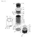
Fig. 2 is an exploded perspective view of the tactile feedback device according to the preferred embodiment of the present invention; -
Fig. 3 is a perspective view showing the constitution in which an actuator, elastic means, linear motion guide, elastic means and main spacer are assembled in the tactile feedback device of the present invention; -
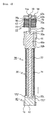
Fig. 4 is a sectional view showing the constitution in which the actuator, touch pins, elastic means, linear motion guide, elastic means and main spacer are assembled in the tactile feedback device of the present invention; -
Fig. 5 is a partially sectional view showing the constitution of the elastic means and main spacers in the tactile feedback device of the present invention; -
Figs. 6A to 6K are partially sectional views showing the constitution of the elastic means in the tactile feedback device of the present invention; -
Fig. 7 is a schematic view showing an operation state in which the touch pins are popped into the housing in the tactile feedback device of the present invention; and -
Fig. 8 is a schematic view showing an operation state in which the touch pins are popped out of the housing in the tactile feedback device of the present invention. - Below will be described a tactile feedback device according to preferred embodiments of the present invention in detail with reference to the accompanying drawings.
- First, referring to
Fig. 1 andFig. 2 , the tactile feedback device of the present invention has ahousing 10 configuring the overall shape. Thehousing 10 comprises abody 12, afirst cover 14, and asecond cover 16. The transverse section of thebody 12 is formed in a hexagon having ahollow space 12a and has opposite opened portions at top and bottom ends. The skin of the user, for example, his or her hand and/or finger, gets close to one end of thehousing 10. For the transverse section of thebody 12, the one formed in a hexagon is illustrated and described, but this is only illustrative, and it may be formed in various shapes such as a polygon, ellipse or circle. The first andsecond covers body 12 so as to close thespace 12a. Thefirst cover 14 has a plurality ofholes 14a formed therethrough. Thebody 12 of thehousing 10, the first andsecond cover - Referring to
Figs. 1 o 4 , anactuator 20 is mounted inside thehousing 10 to convert electric energy into kinetic energy. Theactuator 20 includes a plurality ofelectromagnets 30 and return means 40.Cores 32 ofelectromagnets 30 are mounted in such a way that they can move vertically between a first position P1 and a second position P2 inside thehousing 10 along its lengthwise direction, and are aligned with theholes 14a of thefirst cover 14. At one end of thecores 32 are formedholes 32a aligned with theholes 14a of thefirst cover 14. On the periphery close to one end of thecores 32 is formed afirst flange 32b and at the other end is formed asecond flange 32c. The cross section of thecores 32 may be formed in various shapes such as a circle and polygon. Thecore 32 is preferably made of magnetic material, and it may be made of non-magnetic material, as necessary. - The
coils 34 of theelectromagnets 30 are wound cylindrically on the outside of thecores 32 between first andsecond flanges coil 34 is connected to aconnector 36 mounted on the periphery of thebody 12. Theconnector 36 is a control means for controlling the electric current applied to thecoil 34, and is connected to acontroller 38, microprocessor and computer not shown in drawings. - Referring to
Figs 2 to 4 ,Fig. 7 andFig. 8 , the return means 40 includes a plurality ofmagnets 42 that provide magnetic force so that thecores 32 of theelectromagnets 30 are returned from the second position P2 to the first position P1, that is, the initial position. Themagnets 42 are mounted on one surface of thesecond cover 16 so as to be aligned with thecores 32. The polarity of themagnet 42 is composed so as to generate repulsive force against the polarity that thecore 32 has by forming a magnetic field. - As shown in
Figs. 2 to 4 , theactuator 20 is provided with alinear motion guide 44 that linearly guides the motion of thecore 32. Thelinear motion guide 44 is mounted inside thehousing 10 and has a plurality ofguide holes 44a for one end of thecores 32 to be inserted to pass through. The transverse section of thelinear motion guide 44 is formed in a hexagon corresponding to the transverse section of thehousing 10 so as to prevent rotation inside thehousing 10. In some embodiments, the return means 40 of theactuator 20 may be composed of such a return spring (not shown) mounted between thefirst flange 32b of thecore 32 and thelinear motion guide 44. Although not shown in drawings, theactuator 20 may be composed of a cylindrical coil that forms a magnetic field by the electric current applied from power source and a solenoid type actuator having a plunger mounted so as to move back and forth inside the coil. - Referring to
Figs. 1 to 4 ,Fig. 7 andFig. 8 , the tactile feedback device of the present invention is provided with a plurality oftouch pins 50 that are connected with theactuator 20 so as to be operated by kinetic energy of theactuator 20. The touch pins 50 are mounted so as to pop in and out of theholes 14a of thefirst cover 14. One end of the touch pins 50 (for example, the bottom end inFig. 2 ) is combined with thehole 32a of thecore 32. The other end of the touch pins 50 (for example, the top end inFig. 2 ) is popped out of one end of thehousing 10 through thehole 14a of thefirst cover 14 to be contacted to the skin of the user at the second position P2 of the core 32, and is popped into thehousing 10 through thehole 14a of thefirst cover 14 at the first position P1 of thecore 32. As described herein, the first position P1 is a position where the touch pins 50 are popped in lengthwise direction of thehousing 10 as shown inFig. 7 , and the second position P2 is a position where the touch pins 50 are popped out of thehousing 10 to contact with the finger as shown inFig. 8 . - Referring to
Figs. 2 to 5 , andFigs. 6A to 6K , the tactile feedback device of the present invention is provided with anelastic means 60 mounted between one end of thehousing 10 and theactuator 20 so as to have elastic energy by elastic deformation when the touch pins 50 are popped into thehousing 10. The elastic means 60 consists of one or moreelastic plates 62. Theelastic plate 62 may be made of synthetic rubber, plastic having elastic force, spring plate, etc. On theelastic plates 62 are formed a plurality ofholes 62a, and around theseholes 62a are formedslots 62b for elastic deformation of theelastic plate 62 to be possible in a smooth manner. The touch pins 50 are inserted through theholes 62a of theelastic plates 62. Accordingly, theelastic plates 62 are interlocked with the touch pins 50. -
Figs. 6A to 6I illustrate that theslot 62b of theelastic plate 62 is formed around thehole 62a in a spiral form. One point is supported by anelastic deformation portion 62c around thehole 62a illustrated inFigs. 6A to 6E .Fig. 6J illustrates that theslot 62b of theelastic plate 62 is formed in a zigzag around thehole 62a. Two points are supported by anelastic deformation portion 62c around theholes 62a illustrated inFigs. 6F to 6J . Theelastic deformation portion 62c of theelastic plate 62 illustrated inFig. 6K is formed in a rib shape extended radially around thehole 62a, and theslots 62b are formed in a hole shape between theelastic deformation portions 62c. Three points are supported by theelastic deformation portion 62c around thehole 62a illustrated inFig. 6K . - Referring again to
Figs. 2 to 5 , theelastic plates 62 can have a multi-layer structure in which a single layer or a plurality of layers are laminated therebetween. A plurality ofelastic plates 62 are laminated at a given interval. The attractive force of themagnets 42 is greater than the elastic force that the laminatedelastic plates 62 have. Therefore, thecore 32 overcomes the elastic force of theelastic plates 62 by the attractive force of themagnets 42, and returns smoothly to the first position P1 from the second position P2. In the case that one point is supported by theelastic deformation portion 62c around thehole 62a illustrated inFigs. 6A to 6E , each of theelastic plates 62 is laminated in such a way that theelastic deformation portion 62c forms an equal interval centering around each of theholes 62a. By dint of the fact that theelastic deformation portions 62c of theelastic plates 62 are arrayed at equal intervals, exact linear motion of the touch pins 50 is accomplished. Also in the case of two-point or three-point support structure of the elastic deformation portion 62C, each of theelastic plates 62 is laminated in such a way theelastic deformation portions 62c form equal intervals. - Referring again to
Figs. 2 to 5 ,main spacers 70 are interposed betweenelastic plates 62 to maintain intervals. In themain spacers 70 are formedholes 70a for the touch pins 50 to pass through. The diameters of theholes 70a are formed in such a size that theelastic plates 62 do not interfere with themain spacers 70. Themain spacer 70 may be formed in a ring shape supporting the edge of theelastic plate 62. Also, themain spacer 70 may be substituted by a protruded portion protruding in a ring shape that allows elastic deformation of theelastic deformation portion 62c on the edge of one surface or both surfaces of theelastic plate 62. The respective transverse sections of theelastic plates 62 andmain spacers 70 inFig. 2 are formed in a hexagon corresponding to the transverse section of thebody 12. Thelinear motion guide 44,elastic plates 62 andmain spacers 70 may be forcibly inserted to fit in thespace 12a of thebody 12 or fixed by a fixing means, for example, adhesive agent or epoxy resin. - The
elastic plates 62 of the elastic means 60 are placed between one end of thehousing 10 and thelinear motion guide 44. A plurality ofsubspacers 72 are mounted to maintain the interval between theelastic plate 62 of the lowermost layer of theelastic plates 62 and thelinear motion guide 44. The respective touch pins 50 pass through therespective holes 72a of thesubspacers 72. - Herein after, the action of the tactile feedback device according to the present invention having such a composition will be described.
- Referring to
Fig. 1 ,Fig. 3 andFig. 7 , when the current applied to thecoils 34 of theelectromagnets 30 by control of thecontroller 38 is cut off, the magnetic material, for example, thecores 32 made of steel, sticks to themagnets 42 by the attractive force of the actingmagnets 42, and the touch pins 50 are popped into thehousing 10 through theholes 14a of thefirst cover 14. At the first position P1 where the core 32 sticks to themagnet 42, theelastic deformation portion 62c of theelastic plate 62 is elastically deformed, so elastic energy is stored inside. - Referring to
Fig. 3 andFig. 8 , if current is applied to thecoils 34 of theelectromagnets 30 by control of thecontroller 38 to form a magnetic field, thecores 32 are magnetized by the formed magnetic field so as to have polarity that has repulsive force of themagnets 42 provided. For example, if themagnets 42 generate magnetic force of N pole, thecores 32 are magnetized so as to have N pole. - By mutual action of magnetic force between the
cores 32 andmagnets 42, thecores 32 are moved from first position P1 to second position P2. Thecores 32 are moved linearly along the guide holes 44a of the linear motion guides 44, so that thecores 32 and touch pins 50 are linearly moved together. Meanwhile, as mentioned above, when the current applied to thecoils 34 is cut off, the front ends of the touch pins 50 are popped intohousing 10 through theholes 14a of thefirst cover 14 and thecores 32 are returned to first position P1 from second position P2 by the attractive force of themagnets 42. - During the
cores 32 are moved from first position P1 to second position P2, theelastic deformation portion 62c of theelastic plate 62 is returned by elastic energy stored therein to amplify the kinetic force of the touch pins 50 in conjunction with the linear motion of the touch pins 50. Since the kinetic force of the touch pins 50 is amplified by the repulsive force between thecores 32 andmagnets 42 and the elastic energy of theelastic plate 62 like this, low-power driving ofelectromagnets 30 is possible. Also, since high output of touch pins 50 is possible also by the low-power driving ofelectromagnets 30, it is possible to easily miniaturize the tactile feedback device of the present invention. - When the
cores 32 ofelectromagnets 30 reach the second position P2, the front ends of the touch pins 50 are popped out through theholes 14a of thefirst cover 14 to contact the skin of the user in use. The user can feel haptic sensation from stimulation of the skin by the touch pins 50. By interlocking of theactuator 20 andelastic means 60, the resolution for kinetic force of the touch pins 50 is enhanced, so controllability of the touch pins 50 can be improved. Thecontroller 38 controls the cycle and intensity of the current applied to thecoils 34 so as to make the user feel realistic touch sensation. - Meanwhile, in case of the
cores 32 ofelectromagnets 30 are made of non-magnetic material, thecores 32 of non-magnetic material are magnetized when current is applied to thecoils 34, so they stick to each of themagnets 42 by the attractive force ofmagnets 42. If the current applied to thecoils 34 is cut off, thecores 32 of non-magnetic material come away from themagnets 42 by elastic energy of the elastic means 60 to be moved from first position P1 to second position P2. - As described above, by the tactile feedback device according to the present invention, the touch pins stimulate the skin of the user by dint of the actuator that converts electromagnetic energy into kinetic energy and the interlocking structure of the elastic means, so it is possible to accomplish realistic touch sensation. And additional effects are that the elastic energy of the elastic means amplifies the kinetic force of the touch pins to make low-power/high-output driving of actuator possible, and that it is possible to easily miniaturize and improve the controllability of the touch pins.
- Although the present invention has been described in detail reference to its presently preferred embodiment, it will be understood by those skilled in the art that various modifications and equivalents can be made without departing from the spirit and scope of the present invention, as set forth in the appended claims.
Claims (9)
- A tactile feedback device comprising:a housing which has one end positioned near the skin of the user in use;an actuator which is mounted inside said housing to convert electromagnetic energy into kinetic energy;touch pins which are mounted in such a way that they can pop into and out of said housing, the front ends of which are protruded from one end of said housing to contact the skin of the user, and which are connected to said actuator so as to be operated by kinetic energy of said actuator; andan elastic means which is mounted between one end of said housing and said actuator, into which said touch pins fixedly pass through so as to be interlocked with said touch pins, and which is elastically deformed to have elastic energy when said touch pins are popped into said housing.
- The device of Claim 1, wherein said housing comprises a body having a space in which said actuator, said touch pins and said elastic means are mounted; a first cover which is mounted at one end of said housing and in which holes are formed for said touch pins to pass through; and a second cover which is mounted at the other end of said housing.
- The device of Claim 1 or 2, wherein said actuator mounted inside said housing and combined with said touch pins comprises cores which move between the first position where said touch pins are popped in lengthwise direction of said housing and the second position where said touch pins are popped out of said housing; a plurality of electromagnets having coils which are wound on the periphery of said cores to form a magnetic field that can move said cores between said first position and said second position by applying current; and a return means which returns said cores from said second position to said first position.
- The device of Claim 3, wherein said return means includes a plurality of magnets which are mounted so as to be close to said cores in the opposite direction of said touch pins, and the polarity of said magnets is composed in such a way that repulsive force is generated by said magnetic field against the polarity that said cores have.
- The device of Claim 4, wherein said actuator further comprises a linear motion guide which is mounted inside said housing so as to guide the motion of said core to linear motion, and said linear motion guide has a guide hole for said core to be inserted into to be guided.
- The device of Claim 5, wherein said elastic means is disposed between one end of said housing and said linear motion guide, and has subspacers, into which said touch pins pass through, mounted to maintain intervals between said elastic means and said linear motion guide.
- The device of Claim 1, wherein said elastic means consists of elastic plates, and said elastic plates have a plurality of holes into which said touch pins fixedly pass through, and slots are formed around the holes of said elastic plates for the elastic deformation.
- The device of Claim 7, wherein a plurality of said elastic plates are laminated, and main spacers are interposed respectively to maintain intervals between said elastic plates.
- The device of Claim 8, wherein each of said elastic plates has an elastic deformation portion supported at one point around said hole by the forming of said slot, and each of said elastic plates is laminated in such a way that said elastic deformation portion forms an equal interval centering around each of said holes.
Applications Claiming Priority (1)
| Application Number | Priority Date | Filing Date | Title |
|---|---|---|---|
| KR1020070066393A KR100901359B1 (en) | 2007-07-03 | 2007-07-03 | Tactile device |
Publications (2)
| Publication Number | Publication Date |
|---|---|
| EP2026165A2 true EP2026165A2 (en) | 2009-02-18 |
| EP2026165A3 EP2026165A3 (en) | 2009-04-01 |
Family
ID=40139247
Family Applications (1)
| Application Number | Title | Priority Date | Filing Date |
|---|---|---|---|
| EP08000592A Withdrawn EP2026165A3 (en) | 2007-07-03 | 2008-01-14 | Tactile feedback device |
Country Status (4)
| Country | Link |
|---|---|
| US (1) | US7737828B2 (en) |
| EP (1) | EP2026165A3 (en) |
| JP (1) | JP2009015815A (en) |
| KR (1) | KR100901359B1 (en) |
Families Citing this family (36)
| Publication number | Priority date | Publication date | Assignee | Title |
|---|---|---|---|---|
| KR101463821B1 (en) * | 2008-06-19 | 2014-12-04 | 엘지전자 주식회사 | Portable terminal |
| US8487759B2 (en) | 2009-09-30 | 2013-07-16 | Apple Inc. | Self adapting haptic device |
| JP5399333B2 (en) * | 2010-07-01 | 2014-01-29 | トヨタ自動車株式会社 | Pre air conditioning system |
| US10120446B2 (en) | 2010-11-19 | 2018-11-06 | Apple Inc. | Haptic input device |
| KR20120071895A (en) | 2010-12-23 | 2012-07-03 | 한국전자통신연구원 | Tactile presentation apparatus, tactile cell, and method for controlling tactile presentation apparatus |
| KR101284132B1 (en) * | 2012-03-12 | 2013-07-10 | 한국표준과학연구원 | Dielectricpolymer high-perpormance driver, actuator and vibratingmotor using the driver, method for operating the actuator, apparatus for providing tactile feedback and apparatus for providing tactile feedback to sight and hearing disabled person |
| US9142105B1 (en) | 2012-06-01 | 2015-09-22 | Jonathan M. Crofford | Haptic device capable of managing distributed force |
| US9858774B1 (en) | 2012-06-01 | 2018-01-02 | Jonathan M. Crofford | Haptic device capable of managing distributed force |
| NL1040096C2 (en) * | 2012-11-14 | 2014-09-16 | Holland Haptics B V | Haptic communication system, method and device. |
| US10126817B2 (en) | 2013-09-29 | 2018-11-13 | Apple Inc. | Devices and methods for creating haptic effects |
| CN105683865B (en) | 2013-09-30 | 2018-11-09 | 苹果公司 | Magnetic actuator for haptic response |
| US9317118B2 (en) | 2013-10-22 | 2016-04-19 | Apple Inc. | Touch surface for simulating materials |
| US10276001B2 (en) * | 2013-12-10 | 2019-04-30 | Apple Inc. | Band attachment mechanism with haptic response |
| US10545604B2 (en) | 2014-04-21 | 2020-01-28 | Apple Inc. | Apportionment of forces for multi-touch input devices of electronic devices |
| KR102019505B1 (en) | 2014-09-02 | 2019-09-06 | 애플 인크. | Haptic notifications |
| US10353467B2 (en) | 2015-03-06 | 2019-07-16 | Apple Inc. | Calibration of haptic devices |
| AU2016100399B4 (en) | 2015-04-17 | 2017-02-02 | Apple Inc. | Contracting and elongating materials for providing input and output for an electronic device |
| WO2017044618A1 (en) | 2015-09-08 | 2017-03-16 | Apple Inc. | Linear actuators for use in electronic devices |
| US10039080B2 (en) | 2016-03-04 | 2018-07-31 | Apple Inc. | Situationally-aware alerts |
| US10268272B2 (en) | 2016-03-31 | 2019-04-23 | Apple Inc. | Dampening mechanical modes of a haptic actuator using a delay |
| US10964178B2 (en) | 2016-10-01 | 2021-03-30 | Intel Corporation | Systems, methods and apparatuses for implementing increased human perception of haptic feedback systems |
| US10622538B2 (en) | 2017-07-18 | 2020-04-14 | Apple Inc. | Techniques for providing a haptic output and sensing a haptic input using a piezoelectric body |
| US12158990B2 (en) * | 2018-05-16 | 2024-12-03 | Dot Incorporation | Information output apparatus |
| KR102130776B1 (en) * | 2018-05-16 | 2020-07-08 | 주식회사 닷 | Information output apparatus |
| US12260743B2 (en) | 2018-06-08 | 2025-03-25 | Dot Incorporation | Information output device |
| KR102130777B1 (en) * | 2018-06-08 | 2020-07-08 | 주식회사 닷 | Information output apparatus |
| US10599223B1 (en) | 2018-09-28 | 2020-03-24 | Apple Inc. | Button providing force sensing and/or haptic output |
| US10691211B2 (en) | 2018-09-28 | 2020-06-23 | Apple Inc. | Button providing force sensing and/or haptic output |
| US11380470B2 (en) | 2019-09-24 | 2022-07-05 | Apple Inc. | Methods to control force in reluctance actuators based on flux related parameters |
| KR102811859B1 (en) * | 2019-10-04 | 2025-05-22 | 엘지디스플레이 주식회사 | Haptic Display Device Having 3D Shape Rendering Function |
| KR102741465B1 (en) * | 2019-10-07 | 2024-12-11 | 현대모비스 주식회사 | Touchpad that physically provides the guide and its control method |
| DE102020001685B4 (en) * | 2019-11-28 | 2024-10-02 | Michael Kaiser | Device and method for displaying three-dimensional images |
| CN111796720B (en) * | 2020-07-14 | 2023-11-17 | 北海翰博士科技有限公司 | Touch display screen with clear touch feedback |
| US11977683B2 (en) | 2021-03-12 | 2024-05-07 | Apple Inc. | Modular systems configured to provide localized haptic feedback using inertial actuators |
| US11809631B2 (en) | 2021-09-21 | 2023-11-07 | Apple Inc. | Reluctance haptic engine for an electronic device |
| DE102024124760A1 (en) * | 2024-08-29 | 2026-03-05 | curetec GmbH | Stimulation unit for the directed application of a vibrotactile stimulus |
Citations (1)
| Publication number | Priority date | Publication date | Assignee | Title |
|---|---|---|---|---|
| US20060012576A1 (en) | 2002-12-09 | 2006-01-19 | Commissariat A L'energie Atomique | Multi-layer touch display device comprising electromagnetic actuators |
Family Cites Families (19)
| Publication number | Priority date | Publication date | Assignee | Title |
|---|---|---|---|---|
| US3984708A (en) * | 1975-09-11 | 1976-10-05 | The Institutes Of Medical Sciences | Electromagnetic tactile stimulator |
| JPS5483531A (en) * | 1977-12-13 | 1979-07-03 | Matsushita Electric Industrial Co Ltd | Braille figure display device |
| GR1000807B (en) * | 1991-08-05 | 1993-01-25 | Panagiotis Anagnostopoulos | Methods and apparatus for the touch communimation |
| ES2123804T3 (en) * | 1993-08-04 | 1999-01-16 | Care Tec Gmbh | DEVICE FOR THE REPRESENTATION OF TRANSITIONAL RELIEFS. |
| JPH07244558A (en) * | 1994-03-07 | 1995-09-19 | Sharp Corp | Tactile presentation device |
| JP2802257B2 (en) * | 1996-05-13 | 1998-09-24 | ケージーエス株式会社 | Braille cell module |
| JPH10124736A (en) * | 1996-10-15 | 1998-05-15 | Brother Ind Ltd | Automatic document issuing machine |
| JPH11212446A (en) * | 1998-01-28 | 1999-08-06 | Shinko Electric Co Ltd | Braille display |
| AU5652599A (en) * | 1998-09-22 | 2000-04-10 | Yasufumi Mase | Information processor for visually disabled person and tactile input/output device |
| US6462840B1 (en) * | 1999-05-17 | 2002-10-08 | Grigory Kravtsov | Three dimensional monitor and tactile scanner |
| JP2001147637A (en) * | 1999-11-19 | 2001-05-29 | Yazaki Corp | Braille device and braille display system |
| US6639582B1 (en) * | 2000-08-10 | 2003-10-28 | International Business Machines Corporation | System for combining haptic sensory-motor effects from two separate input devices into resultant sensory-motor effects and for feedback of such resultant effects between the input devices |
| JP3597129B2 (en) * | 2000-11-17 | 2004-12-02 | Necアクセステクニカ株式会社 | Braille display |
| US20020080111A1 (en) * | 2000-12-27 | 2002-06-27 | Lake Adam T. | Method and apparatus to input and output haptic data |
| US7352356B2 (en) * | 2001-12-13 | 2008-04-01 | United States Of America | Refreshable scanning tactile graphic display for localized sensory stimulation |
| DE10209385A1 (en) * | 2002-03-02 | 2003-09-11 | Markus Jungmann | Tactile surface-structure and contour representing device for tele-manipulation, virtual reality or braille, has voltage applied between adjacent electrode layers separated by elastic insulating material to cause lift |
| JP2004219558A (en) * | 2003-01-10 | 2004-08-05 | Yamaha Corp | Image display |
| JP2005216110A (en) * | 2004-01-30 | 2005-08-11 | Nissan Motor Co Ltd | Information operation device |
| JP2005266357A (en) * | 2004-03-18 | 2005-09-29 | Seiko Epson Corp | Tactile display and tactile display system |
-
2007
- 2007-07-03 KR KR1020070066393A patent/KR100901359B1/en not_active Expired - Fee Related
-
2008
- 2008-01-14 EP EP08000592A patent/EP2026165A3/en not_active Withdrawn
- 2008-01-17 US US12/009,382 patent/US7737828B2/en active Active
- 2008-02-05 JP JP2008024630A patent/JP2009015815A/en not_active Ceased
Patent Citations (1)
| Publication number | Priority date | Publication date | Assignee | Title |
|---|---|---|---|---|
| US20060012576A1 (en) | 2002-12-09 | 2006-01-19 | Commissariat A L'energie Atomique | Multi-layer touch display device comprising electromagnetic actuators |
Also Published As
| Publication number | Publication date |
|---|---|
| KR100901359B1 (en) | 2009-06-05 |
| US20090009301A1 (en) | 2009-01-08 |
| JP2009015815A (en) | 2009-01-22 |
| US7737828B2 (en) | 2010-06-15 |
| KR20090003604A (en) | 2009-01-12 |
| EP2026165A3 (en) | 2009-04-01 |
Similar Documents
| Publication | Publication Date | Title |
|---|---|---|
| US7737828B2 (en) | Tactile feedback device | |
| Yang et al. | A survey on tactile displays for visually impaired people | |
| EP3305383A1 (en) | Haptic actuator incorporating electropermanent magnet | |
| EP2060965A1 (en) | Haptic module using magnetic force and electronic apparatuses having the module | |
| Yang et al. | Development of a miniature pin-array tactile module using elastic and electromagnetic force for mobile devices | |
| JP4652058B2 (en) | Multi-layer touch sensitive display device with electromagnetic actuator | |
| CN105556422B (en) | A device that uses magnetic fields to generate a sense of touch | |
| CN105281533A (en) | Linear actuator | |
| US20190214174A1 (en) | Bi-stable actuator based on electromagnetic attraction | |
| KR102756008B1 (en) | Haptic Device and Haptic Module | |
| JP4608531B2 (en) | Electromagnetic actuator | |
| JP4546894B2 (en) | Tactile information presentation actuator | |
| Szabo et al. | Development of wearable micro-actuator array for 3-D virtual tactile displays | |
| Hernandez et al. | Characterization of a piezoelectric ultrasonic linear motor for Braille displays | |
| KR20110036142A (en) | External force response haptic providing device using electromagnetic induction phenomenon, haptic providing module using the same, portable terminal using the same and its control method | |
| Kim et al. | A new modular pin-array tactile device | |
| KR100904389B1 (en) | Thin Tactile Device | |
| KR101322941B1 (en) | A compact linear actuator | |
| KR101284132B1 (en) | Dielectricpolymer high-perpormance driver, actuator and vibratingmotor using the driver, method for operating the actuator, apparatus for providing tactile feedback and apparatus for providing tactile feedback to sight and hearing disabled person | |
| US20210200314A1 (en) | Tactile fedback by a longitudinally moved magnetic hammer | |
| Karpelson et al. | Low-cost electromechanical actuator arrays for tactile display applications | |
| KR100887714B1 (en) | Reaction force generation module using magnetic force and electronic device employing same | |
| KR20240058391A (en) | Actuator, output device and input device | |
| KR101335025B1 (en) | A compact linear actuator having minimal height | |
| KR20250050951A (en) | Rotary solenoid micro actuator with drive coil |
Legal Events
| Date | Code | Title | Description |
|---|---|---|---|
| PUAI | Public reference made under article 153(3) epc to a published international application that has entered the european phase |
Free format text: ORIGINAL CODE: 0009012 |
|
| 17P | Request for examination filed |
Effective date: 20080114 |
|
| AK | Designated contracting states |
Kind code of ref document: A2 Designated state(s): AT BE BG CH CY CZ DE DK EE ES FI FR GB GR HR HU IE IS IT LI LT LU LV MC MT NL NO PL PT RO SE SI SK TR |
|
| AX | Request for extension of the european patent |
Extension state: AL BA MK RS |
|
| PUAL | Search report despatched |
Free format text: ORIGINAL CODE: 0009013 |
|
| AK | Designated contracting states |
Kind code of ref document: A3 Designated state(s): AT BE BG CH CY CZ DE DK EE ES FI FR GB GR HR HU IE IS IT LI LT LU LV MC MT NL NO PL PT RO SE SI SK TR |
|
| AX | Request for extension of the european patent |
Extension state: AL BA MK RS |
|
| 17Q | First examination report despatched |
Effective date: 20091021 |
|
| AKX | Designation fees paid |
Designated state(s): AT BE BG CH CY CZ DE DK EE ES FI FR GB GR HR HU IE IS IT LI LT LU LV MC MT NL NO PL PT RO SE SI SK TR |
|
| STAA | Information on the status of an ep patent application or granted ep patent |
Free format text: STATUS: THE APPLICATION IS DEEMED TO BE WITHDRAWN |
|
| 18D | Application deemed to be withdrawn |
Effective date: 20120801 |