EP2026057A2 - Optical flow cell for use in high temperature and/or high pressure environments - Google Patents
Optical flow cell for use in high temperature and/or high pressure environments Download PDFInfo
- Publication number
- EP2026057A2 EP2026057A2 EP08252417A EP08252417A EP2026057A2 EP 2026057 A2 EP2026057 A2 EP 2026057A2 EP 08252417 A EP08252417 A EP 08252417A EP 08252417 A EP08252417 A EP 08252417A EP 2026057 A2 EP2026057 A2 EP 2026057A2
- Authority
- EP
- European Patent Office
- Prior art keywords
- flow
- flow cell
- retainer
- disposed
- fluid
- Prior art date
- Legal status (The legal status is an assumption and is not a legal conclusion. Google has not performed a legal analysis and makes no representation as to the accuracy of the status listed.)
- Withdrawn
Links
- 230000003287 optical effect Effects 0.000 title description 24
- 239000012530 fluid Substances 0.000 claims abstract description 78
- 239000002245 particle Substances 0.000 claims description 25
- 230000007704 transition Effects 0.000 claims description 12
- 229910001220 stainless steel Inorganic materials 0.000 claims description 6
- 239000010935 stainless steel Substances 0.000 claims description 6
- 230000006835 compression Effects 0.000 claims description 3
- 238000007906 compression Methods 0.000 claims description 3
- 239000011521 glass Substances 0.000 claims description 3
- 238000007789 sealing Methods 0.000 abstract description 2
- 238000012544 monitoring process Methods 0.000 abstract 1
- 238000003384 imaging method Methods 0.000 description 11
- 239000000463 material Substances 0.000 description 7
- 230000008901 benefit Effects 0.000 description 4
- 239000000446 fuel Substances 0.000 description 4
- 239000007788 liquid Substances 0.000 description 4
- 230000001050 lubricating effect Effects 0.000 description 4
- 230000000712 assembly Effects 0.000 description 3
- 238000000429 assembly Methods 0.000 description 3
- 230000036541 health Effects 0.000 description 3
- 238000012634 optical imaging Methods 0.000 description 3
- 238000002485 combustion reaction Methods 0.000 description 2
- 230000007613 environmental effect Effects 0.000 description 2
- 230000007246 mechanism Effects 0.000 description 2
- 238000000034 method Methods 0.000 description 2
- 230000000717 retained effect Effects 0.000 description 2
- 239000006227 byproduct Substances 0.000 description 1
- 230000000295 complement effect Effects 0.000 description 1
- 238000011109 contamination Methods 0.000 description 1
- 238000001816 cooling Methods 0.000 description 1
- 230000001934 delay Effects 0.000 description 1
- 238000001514 detection method Methods 0.000 description 1
- 238000010586 diagram Methods 0.000 description 1
- 230000003993 interaction Effects 0.000 description 1
- 238000005461 lubrication Methods 0.000 description 1
- 238000012423 maintenance Methods 0.000 description 1
- 239000002923 metal particle Substances 0.000 description 1
- 238000005381 potential energy Methods 0.000 description 1
- 239000012780 transparent material Substances 0.000 description 1
Images


Classifications
-
- G—PHYSICS
- G01—MEASURING; TESTING
- G01N—INVESTIGATING OR ANALYSING MATERIALS BY DETERMINING THEIR CHEMICAL OR PHYSICAL PROPERTIES
- G01N21/00—Investigating or analysing materials by the use of optical means, i.e. using sub-millimetre waves, infrared, visible or ultraviolet light
- G01N21/01—Arrangements or apparatus for facilitating the optical investigation
- G01N21/03—Cuvette constructions
- G01N21/09—Cuvette constructions adapted to resist hostile environments or corrosive or abrasive materials
-
- G—PHYSICS
- G01—MEASURING; TESTING
- G01N—INVESTIGATING OR ANALYSING MATERIALS BY DETERMINING THEIR CHEMICAL OR PHYSICAL PROPERTIES
- G01N21/00—Investigating or analysing materials by the use of optical means, i.e. using sub-millimetre waves, infrared, visible or ultraviolet light
- G01N21/01—Arrangements or apparatus for facilitating the optical investigation
- G01N21/03—Cuvette constructions
- G01N21/05—Flow-through cuvettes
- G01N2021/058—Flat flow cell
Definitions
- the present invention relates to an optical flow cell for analyzing fluids. More specifically, the present invention relates to an online optical flow cell for analyzing fluids. Particularly, the present invention relates to an online optical flow cell that provides laminar flow of fluids through a flow channel, and which is able to withstand elevated environmental pressures and/or temperatures during its operation.
- Operating fluids including but not limited to lubricating fluid, hydraulic fluid, and liquid fuels, are used in various mechanical assemblies to perform a particular task.
- lubricating fluid is used within a mechanical assembly to provide cooling and lubrication to the parts.
- Hydraulic fluid is pressurized by a pump to actuate a piston in order to generate a moving force.
- liquid fuels provide a source of potential energy to various types of fuel driven engines.
- These fluids are generally used in mechanical assemblies where the fluids come in contact, or otherwise interact with, various supply lines, valves, reservoirs, pumps, and engines, as well as various other mechanical assemblies. As a result of this interaction, wear particles generated by moving parts within the machine as well as contamination particles from outside the machine are present in the fluid.
- lubricating fluid such as oil
- an operating machine such as a combustion engine
- lubricating fluid such as oil
- an operating machine such as a combustion engine
- these particles which are typically on the order of about 150 microns or less, are indicative of the overall wear of the engine.
- the physical characteristics such as the size and shape of the particles in real-time, the current wear or "health" of the engine can be identified on an on-demand basis.
- fluid analysis systems which utilize laser optical near-field imaging techniques. These systems comprise a laser light source, a light detection device, a flow cell, and a pump or other means to draw the fluid through the flow cell.
- a flow cell utilizing near-field imaging techniques is disclosed in U.S. Patent No. 6,104,483 , which is incorporated herein by reference.
- This system determines the number of particles in the fluid, and then identifies the size and physical characteristics of the particle. Because the physical characteristics of a particle directly correspond to a particular wear mechanism or phenomena, the system can correlate the detected particle characteristics with the particular mechanism causing the wear, such as metal particles created by engine wear or debris entering through the air intake of an engine. As such, the system informs the user as to the source of the particles, thereby enabling the user to more accurately diagnose and remedy any engine problems that may exist.
- an optical flow cell that is configured to provide laminar flow of the operating fluid passing therethrough. Moreover, there is a need in the art for an optical flow cell that is configured to withstand environments having high pressure and/or high temperature, while providing laminar flow to the operating fluid passing therethrough.
- It is another aspect of the present invention to provide a flow cell to monitor particles in a fluid comprising a body having a body aperture therethough forming a wall surface, a pair of slits disposed within opposing sides of the wall surface, wherein one of the slits receives an incoming flow of fluid, and the other slit receives an outgoing flow of fluid, a pair of spaced transparent plates disposed within the aperture, the space between the plates defining a flow channel substantially aligned with each of the slits allowing the fluid to pass therethrough in a laminar manner, and a retainer attached to the body to retain the plates in place, the retainer having a retainer aperture, wherein the body aperture, the flow channel, and the retainer aperture are substantially aligned to allow light to pass threrethrough.
- FIG. 1 An online optical flow cell in accordance with the concepts of the present invention is generally referred to by the numeral 10 as shown in Fig. 1 of the drawings.
- operating fluid is defined as any fluid, including but not limited to lubricating fluid, hydraulic fluid, and liquid fuels, or the like. As such, it will be appreciated that any type of fluid could be passed through the optical flow cell described herein.
- the flow cell 10 is generally utilized with a fluid analysis system 12 that includes several components that allows wear particles, or any other particle within a flow of operating fluid to be detected.
- the optical flow cell 10 maintains a transparent viewing area 20 that is configured to receive collimated light, such as a laser light, from a light source 30 maintained by the system 12.
- Operating fluid from an operating machine is drawn into the flow cell 10 via a flow delivery device, such as a pump 50.
- the flow of operating fluid is modified to provide a laminar flow through the flow channel that passes through the viewing area 20.
- the light delivered from the light source 30 passes through the laminar flow within the transparent viewing area 20 and generates images that are detected by an imaging and analysis device 60.
- the images detected by the imaging and analysis device 60 are then analyzed to determine the particular shape of the wear particles that are suspended in the operating fluid. Once imaged, the operating fluid exits the flow cell 10 and returns to the operating machine.
- the optical imaging system is able to achieve a more accurate and consistent identification of wear particles in such environments over prior art systems.
- the flow cell 10 allows the optical imaging system to more accurately predict wear and generate predictive maintenance schedules in order to avoid operational delays that result when the operating machine is taken off-line or is otherwise made non-functional due to wear of its mechanical components.
- the optical flow cell 10 may be used with an optical imaging system, such as that discussed in U.S Patent Application No. 11/228,172 to monitor operating fluid for a machine, such as an engine, although any other suitable imaging system may be utilized.
- the flow cell 10 as discussed below is configured for online analysis of operating fluid maintained by an operating machine or other device, whereby the flow cell 10 is coupled directly thereto.
- the flow cell 10 is configured to receive a continuous sample of a portion of the aggregate operating fluid that is maintained by the operating machine or device. The continuous sample of operating fluid is analyzed, and then returned back to the aggregate supply.
- the flow cell 10 may be readily adapted for use in other manners, such as off-line and inline for example.
- the flow cell 10 comprises a body 110 having an outer surface 114 that is opposite a facing surface 118.
- the outer surface and facing surface 114,118 are connected by end surfaces 120 and 124 and corresponding side surfaces.
- the body 110 may be formed from stainless steel or any other material that is able to withstand environments with elevated temperatures and/or pressures.
- the body 110 includes a body aperture 134 therethrough, which enables light from the light source 30 to pass through during the operation of the flow cell 10.
- a flow channel assembly 136 that is retained therewithin by a retainer 140, which has a retainer aperture 144 that is aligned with the body aperture 134, when attached to the outer surface 114 of the body 110.
- the flow channel assembly 136 comprises various components that coact to form a transparent flow channel 138.
- the flow channel 138 is aligned with a pair of opposing flow slits 146,148 provided by the body 110.
- the body 110 has bores 160 and 162 in corresponding end surfaces 120 and 124.
- Operating fluid passes through the flow slits 146,148 and the flow channel 138 via inlet and outlet tubes 150 and 154 that are received and retained within respective bores 160 and 162 by respective threaded collars 170 and 174.
- the flow slits 146,148 and the flow channel 138 serve to impart a laminar flow to the operating fluid that enters the inlet tube 150 and exits the outlet tube 154.
- the retainer aperture 144 and the body aperture 134 are aligned with each other, the imaging light from the fluid analysis system passes through the transparent flow channel 138.
- the body aperture 134 of the flow cell 10 includes a wall 190 having an upper edge 200 that is adjacent the outer surface 114 of the body 110.
- a support shelf 210 extends from the wall 190 forming a lower edge 214 that is adjacent the facing surface 118 of the body 110.
- Disposed about the periphery of the upper edge 200 is an outer channel 220, and arranged about the periphery of the lower edge 214, and recessed within the shelf 210 is an inner channel 230.
- disposed about the periphery of upper edge 200 are a plurality of threaded bores 240A-D that extend through the body 110 to facilitate the attachment of the retainer 140 discussed in detail below.
- the flow assembly 136 comprises a lower seal 300 that is seated, or otherwise disposed within the inner channel 230. Disposed upon the lower seal 300 is a lower transparent plate 310, that is separated from an upper transparent plate 320 by a pair of laterally spaced shims 330A and 330B.
- the plates 310 and 320 may comprise transparent glass or any other suitable transparent material that is capable of withstanding operating environments having elevated temperatures and/or pressures.
- the shims 330A-B may be formed from stainless steel, or any other material capable of withstanding environments with elevated temperatures and/or pressures.
- the shims 330A-B are arranged so that their respective facing edges 331 and 332 are spaced apart at a distance that matches the width dimension of the slits 146 and 148. Referring to Fig. 7 , as well as to the other Figs., it should be appreciated that the height dimension of the shims 330A-B substantially matches the height dimension of the slits 146,148, so as to allow the flow channel 138 to be substantially aligned with the inlet and outlet slits 146,148.
- the spaced plates 310,320 define the height of the flow cell 138, while the spaced edges 331 and 332 of the spaced shims 330A-B define the width of the flow channel 20.
- the edges 331,332 of the shims 330A-B are aligned with the vertical edges of the slits 146,148, while the lower and upper plates 310,320 are aligned with the respective lower and upper horizontal edges of the slits 146,148.
- the flow channel assembly 136 includes an external seal 360 that is disposed within the outer channel 220.
- the seals 300, 350, and 360 may comprise rubber seals or any other suitable sealing means.
- the retainer 140 is attached to the body 110 of the flow cell 10 in the manner to be discussed.
- the retainer 140 provides inner and outer surfaces 400 and 410 through which a plurality of attachment bores 420A-D pass. As shown in Fig. 2 , the attachment bores 420A-D allow the retainer 140 to be attached to the body 110 by fasteners 422A-D received therethrough, which are received by the threaded bores 240A-D maintained by the body 110. It should be appreciated, that the fasteners 422A-D may be comprised of stainless steel, although any other suitable material may be used.
- the retainer 140 On its inner surface 400, the retainer 140 maintains inner and outer concentrically arranged compression steps 430 and 440. The inner and outer compression steps 430,440 are configured to respectively provide a direct compressive force to the upper seal 350 and external seal 360.
- a lateral step 450 provides a lateral force to the upper seal 350 to ensure that it forms a seal against the wall 190 of the body aperture 134.
- the retainer 140 provides indirect compressive force to the lower seal 300, as well as to the plates 310,320 and shims 330A-B to assist in retaining them in place.
- the body 110 also includes threaded bores 160,162, which are disposed at each end surface 120 and 124 of the body 110 of the flow cell 10.
- the threaded retainers 170,174 are threadably received within the bores 160,162 to retain the inlet and outlet tubes 150,154 therein.
- the inlet tube 150 carries operating fluid to the flow channel 20, while the outlet tube 154 carries the operating fluid away from the flow channel 20.
- either end 124 of the flow cell 10 may serve as an inlet or outlet of operating fluid.
- the bores 160,162 extend within the body 110 of the flow cell 10, with their cross-sectional shape transitioning to a nozzle end 500,502 having a somewhat cylindrical shape.
- the transition flow area 510,512 is comprised of a substantially flat surface that is defined by a radiused wall 516,518 and the wall 190 within the body aperture 134. It should be appreciated, that the radiused wall 516,518 are not required to be radially dimensioned as shown in Fig. 11 , and may take on any desired profile or dimension.
- the nozzle end 500,502, the nozzle transition 506,508, and the transition flow are 510,512 fluidly communicate so as to condition the operating fluid before it passes into the rectangular flow slits 146,148 that are disposed within the wall 190 of the body aperture 134.
- the rectangular cross-section of the flow slits 146,148, and the rectangular cross-section of the flow channel 20 contributes to the laminar flow imparted to the operating fluid as it passes through the viewing area 20.
- the flow cell 10 may include one or more mounting bores 520A-D, configured to receive a suitable fastener therethrough, for mounting the flow cell 10 in a desired location.
- the flow cell 10 Due to the configuration of the flow cell 10, and its ability to be manufactured at a reduced size, it can be used to monitor operating fluid in confined areas and in environments which have elevated temperatures and/or pressures.
- the flow cell 10 may be used in environments having a pressure of up to about 400 psi (pounds per square inch) and temperatures in the range of -40 degrees Celsius to 120 degrees Celsius, although such should not be construed as limiting as the flow cell 10 may be utilized in environments with other pressure and/or temperature ranges.
- the flow cell 10 is able to achieve its operational performance in high temperature and/or high-pressure environments, while maintaining the integrity of the glass plates 310 and 320 that define the flow channel 138, due at least in part to the particular selection of materials used to form the flow channel 138. That is, the selection of the particular materials utilized to comprise the body 110, the retainer 140, the shims 330A-B, and the fasteners 422A-D allow the flow cell 10 to retain its ability to provide a laminar flow of operating fluid through the flow cell 138 at elevated pressures and/or temperatures.
- the materials comprising the body 110, the retainer 140, the shims 330A-B, and the fasteners 422A-D are selected so that the thermal expansion coefficients of those materials used complement each other, so as to prevent any rupture or failure of the flow channel 138 as the environmental temperatures and/or pressures to which the flow cell 10 is subjected vary.
- operating fluid from the engine, operating machine, or other device utilizing the operating fluid is drawn into the flow cell 10 by the inlet tube 150, via the pump 50 or other means that is operatively coupled to the outlet tube 154.
- the light source 30 maintained by the fluid analysis system 12 is positioned proximate the outer surface 114, and directs a light beam, such as a laser, though the transparent flow channel 20.
- the imaging and analysis device 60 is arranged so as to receive the light passing through the flow channel 20. As the operating fluid is received from the inlet tube 150, it is channeled through the nozzle 500, into the inlet flow slit 146, and into the flow channel 20.
- the inlet flow slit 146, flow channel 20, and the outlet flow slit 148 serves to take the flow of the operating fluid, which may be characterized by turbulence, and normalizes it into a laminar flow that is generally devoid of turbulence and other disturbances.
- the light passing through the laminar flow of operating fluid forms an imaging signal detected by the imaging and analysis device 60 that represents the various wear particles suspended within the operating fluid.
- the laminar flow of the operating fluid through the flow channel 20 allows any wear particles suspended in the operating fluid to be oriented in a consistent manner so that the characteristic shape of the wear particle can be determined by the fluid analysis system 12. As such, the fluid analysis system 12 is able to more accurately predict the level of wear being experienced by the engine or other mechanical machine.
- the operating fluid passes through the flow chamber 20, it exits through the outlet tube 154 via the outlet flow slit 148.
- a flow cell may be used to impart a laminar flow to operating fluid as it passes through a flow channel. Still another advantage of the present invention is that the flow cell may operate in environments with elevated temperatures and/or pressures. Yet another advantage of the present invention is that wear particles within the operating fluid passing through the flow channel are oriented more consistently so that the shape of the wear particle can be characterized more accurately by an imaging system.
Landscapes
- Physics & Mathematics (AREA)
- Health & Medical Sciences (AREA)
- Life Sciences & Earth Sciences (AREA)
- Chemical & Material Sciences (AREA)
- Analytical Chemistry (AREA)
- Biochemistry (AREA)
- General Health & Medical Sciences (AREA)
- General Physics & Mathematics (AREA)
- Immunology (AREA)
- Pathology (AREA)
- Optical Measuring Cells (AREA)
Abstract
A flow cell (10) for monitoring operating fluid in an environment with elevated temperature and/or pressure comprises a body (110) having a body aperture (134). The body aperture (134) provides opposing inlet and outlet flow slits (146, 148) that are disposed within a wall (190) maintained by the body aperture (134). The body aperture (134) is configured to receive upper and low transparent plates (320, 310) that are separated by a pair of spaced shims (330A, 330B). The spaced shims define a flow channel (138) between the plates (320, 310), which is aligned with the inlet and outlet flow slits (146, 148). A retainer (140) is attached by suitable fasteners to retain the plates and shims in place, and thus sealing the flow of operating fluid through the flow channel (138) from the external environment.
Description
- Generally, the present invention relates to an optical flow cell for analyzing fluids. More specifically, the present invention relates to an online optical flow cell for analyzing fluids. Particularly, the present invention relates to an online optical flow cell that provides laminar flow of fluids through a flow channel, and which is able to withstand elevated environmental pressures and/or temperatures during its operation.
- Operating fluids, including but not limited to lubricating fluid, hydraulic fluid, and liquid fuels, are used in various mechanical assemblies to perform a particular task. For example, lubricating fluid is used within a mechanical assembly to provide cooling and lubrication to the parts. Hydraulic fluid is pressurized by a pump to actuate a piston in order to generate a moving force. And liquid fuels provide a source of potential energy to various types of fuel driven engines. These fluids are generally used in mechanical assemblies where the fluids come in contact, or otherwise interact with, various supply lines, valves, reservoirs, pumps, and engines, as well as various other mechanical assemblies. As a result of this interaction, wear particles generated by moving parts within the machine as well as contamination particles from outside the machine are present in the fluid. These particles by themselves are not a problem for the machine because they are being removed by the oil filter. However, they are an indication of the type of wear going on within the machine. By knowing the type of wear particles being generated and their size, concentration and trend, a prediction on the health of the machine can be made. By knowing the health of the machine, servicing need only be done when it is required: saving time, money, and increasing the life of the machine.
- For example, lubricating fluid, such as oil, used by an operating machine, such as a combustion engine, is often contaminated by the result of: combustion by-products, debris that has entered the air intake of the engine, and other particles that are the result of the wear of the internal parts of the engine. In particular, these particles, which are typically on the order of about 150 microns or less, are indicative of the overall wear of the engine. Moreover, by analyzing the physical characteristics, such as the size and shape of the particles in real-time, the current wear or "health" of the engine can be identified on an on-demand basis.
- As a result, several systems that directly analyze the various operating fluids of an engine or other operating machine have been developed. One method, referred to as the "offline" method involves extracting a sample of operating fluid, and then sending the sample to a remotely located laboratory for analysis. Although this system is effective, it is time consuming as the analysis requires a substantial lead time from the time the sample is taken and until wear results are obtained.
- Recently, fluid analysis systems have been developed, which utilize laser optical near-field imaging techniques. These systems comprise a laser light source, a light detection device, a flow cell, and a pump or other means to draw the fluid through the flow cell. One such type of flow cell utilizing near-field imaging techniques is disclosed in
U.S. Patent No. 6,104,483 , which is incorporated herein by reference. This system determines the number of particles in the fluid, and then identifies the size and physical characteristics of the particle. Because the physical characteristics of a particle directly correspond to a particular wear mechanism or phenomena, the system can correlate the detected particle characteristics with the particular mechanism causing the wear, such as metal particles created by engine wear or debris entering through the air intake of an engine. As such, the system informs the user as to the source of the particles, thereby enabling the user to more accurately diagnose and remedy any engine problems that may exist. - Although the utilization of laser optical near-field imaging techniques provided by the flow cell have proven to be a significant advance in the prospect of real-time wear analysis, such systems are plagued by various limitations. For example, while manufacturers have overcome the technical obstacles associated with the operation of the flow cell at high temperature and/or high pressure, they have been unable to provide a flow cell that has a compact dimension, is lightweight, and cost effective, and which is able to maintain a laminar flow of the operating fluid therethrough. A laminar flow is advantageous in that it allows wear particles to pass uniformly through the flow cell, allowing a fluid analysis system to more accurately characterize the shape of the wear particles.
- Therefore, there is a need in the art for an optical flow cell that is configured to provide laminar flow of the operating fluid passing therethrough. Moreover, there is a need in the art for an optical flow cell that is configured to withstand environments having high pressure and/or high temperature, while providing laminar flow to the operating fluid passing therethrough.
- In light of the foregoing, it is a first aspect of the present invention to provide an optical flow cell for use in high temperature and/or high pressure environments.
- It is another aspect of the present invention to provide a flow cell to monitor particles in a fluid comprising a body having a body aperture therethough forming a wall surface, a pair of slits disposed within opposing sides of the wall surface, wherein one of the slits receives an incoming flow of fluid, and the other slit receives an outgoing flow of fluid, a pair of spaced transparent plates disposed within the aperture, the space between the plates defining a flow channel substantially aligned with each of the slits allowing the fluid to pass therethrough in a laminar manner, and a retainer attached to the body to retain the plates in place, the retainer having a retainer aperture, wherein the body aperture, the flow channel, and the retainer aperture are substantially aligned to allow light to pass threrethrough.
- These and other features and advantages of the present invention will become better understood with regard to the following description, appended claims, and accompanying drawings wherein:
-
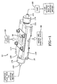
Fig. 1 is a block diagram showing an optical flow cell utilized with a fluid analysis system in accordance with the concepts of the present invention; -
Fig. 2 is an exploded perspective view of an optical flow cell in accordance with the concepts of the present invention; -
Fig. 3 is a bottom perspective view of the optical flow cell in accordance with the concepts of the present invention. -
Fig. 4 is a perspective view of the optical flow cell with attached retainer in accordance with the concepts of the present invention; -
Fig. 5 is a perspective cross-sectional view of the optical flow cell in accordance with the concepts of the present invention; -
Fig. 6 is a perspective cross-sectional view of the optical flow cell in accordance with the concepts of the present invention; -
Fig. 7 is a perspective cross-sectional view of the optical flow cell in accordance with the concepts of the present invention; -
Fig. 8 is a cross-sectional view of the optical flow cell in accordance with the concepts of the present invention; -
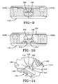
Fig. 9 is a cross-sectional view of the optical flow cell taken along line 9-9 in accordance with the concepts of the present invention; -
Fig. 10 is a cross-sectional view of the optical flow cell taken along line 10-10 in accordance with the concepts of the present invention; and -
Fig. 11 is a perspective view of the optical flow cell showing a flow slit in accordance with the concepts of the present invention. - An online optical flow cell in accordance with the concepts of the present invention is generally referred to by the
numeral 10 as shown inFig. 1 of the drawings. Before discussing the particular aspects of theflow cell 10, a general overview of its operation will be set forth below. Furthermore, the term "operating fluid," as used herein, is defined as any fluid, including but not limited to lubricating fluid, hydraulic fluid, and liquid fuels, or the like. As such, it will be appreciated that any type of fluid could be passed through the optical flow cell described herein. - The
flow cell 10 is generally utilized with afluid analysis system 12 that includes several components that allows wear particles, or any other particle within a flow of operating fluid to be detected. To achieve such operation, theoptical flow cell 10 maintains atransparent viewing area 20 that is configured to receive collimated light, such as a laser light, from alight source 30 maintained by thesystem 12. Operating fluid from an operating machine is drawn into theflow cell 10 via a flow delivery device, such as apump 50. As the operating fluid enters theflow cell 10, the flow of operating fluid is modified to provide a laminar flow through the flow channel that passes through theviewing area 20. During this time, the light delivered from thelight source 30 passes through the laminar flow within thetransparent viewing area 20 and generates images that are detected by an imaging andanalysis device 60. The images detected by the imaging andanalysis device 60 are then analyzed to determine the particular shape of the wear particles that are suspended in the operating fluid. Once imaged, the operating fluid exits theflow cell 10 and returns to the operating machine. Thus, because the operating fluid within theflow cell 10 has a laminar flow, and because theflow cell 10 is configured to withstand elevated temperatures and/or pressures generated by the operating machine, the optical imaging system is able to achieve a more accurate and consistent identification of wear particles in such environments over prior art systems. As such, theflow cell 10 allows the optical imaging system to more accurately predict wear and generate predictive maintenance schedules in order to avoid operational delays that result when the operating machine is taken off-line or is otherwise made non-functional due to wear of its mechanical components. Thus, with the background of the operation of theflow cell 10 set forth, the specific structural aspects of theflow cell 10 will now be presented. It should also be appreciated that theoptical flow cell 10 may be used with an optical imaging system, such as that discussed in U.S Patent Application No. 11/228,172 to monitor operating fluid for a machine, such as an engine, although any other suitable imaging system may be utilized. - The
flow cell 10 as discussed below is configured for online analysis of operating fluid maintained by an operating machine or other device, whereby theflow cell 10 is coupled directly thereto. Thus, theflow cell 10 is configured to receive a continuous sample of a portion of the aggregate operating fluid that is maintained by the operating machine or device. The continuous sample of operating fluid is analyzed, and then returned back to the aggregate supply. However, it should be appreciated that theflow cell 10 may be readily adapted for use in other manners, such as off-line and inline for example. - As shown in
Figs. 2 and3 theflow cell 10 comprises abody 110 having anouter surface 114 that is opposite a facingsurface 118. The outer surface and facing surface 114,118 are connected byend surfaces body 110 may be formed from stainless steel or any other material that is able to withstand environments with elevated temperatures and/or pressures. Thebody 110 includes abody aperture 134 therethrough, which enables light from thelight source 30 to pass through during the operation of theflow cell 10. Within thebody aperture 134 is disposed aflow channel assembly 136 that is retained therewithin by aretainer 140, which has aretainer aperture 144 that is aligned with thebody aperture 134, when attached to theouter surface 114 of thebody 110. - The
flow channel assembly 136 comprises various components that coact to form atransparent flow channel 138. As will be discussed in more detail, theflow channel 138 is aligned with a pair of opposing flow slits 146,148 provided by thebody 110. Thebody 110 hasbores flow channel 138 via inlet andoutlet tubes respective bores collars flow cell 10, the flow slits 146,148 and theflow channel 138 serve to impart a laminar flow to the operating fluid that enters theinlet tube 150 and exits theoutlet tube 154. In addition, because theretainer aperture 144 and thebody aperture 134 are aligned with each other, the imaging light from the fluid analysis system passes through thetransparent flow channel 138. - As shown in the Figs, and more clearly in
Figs. 5 and6 , thebody aperture 134 of theflow cell 10 includes awall 190 having anupper edge 200 that is adjacent theouter surface 114 of thebody 110. Within the body aperture 134 asupport shelf 210 extends from thewall 190 forming alower edge 214 that is adjacent the facingsurface 118 of thebody 110. Disposed about the periphery of theupper edge 200 is anouter channel 220, and arranged about the periphery of thelower edge 214, and recessed within theshelf 210 is aninner channel 230. Furthermore, disposed about the periphery ofupper edge 200 are a plurality of threaded bores 240A-D that extend through thebody 110 to facilitate the attachment of theretainer 140 discussed in detail below. - Referring in particular to
Figs. 2 ,4 ,5 ,6 , and7 , disposed within thebody aperture 134 of theflow cell 10 is theflow assembly 136. Theflow assembly 136 comprises alower seal 300 that is seated, or otherwise disposed within theinner channel 230. Disposed upon thelower seal 300 is a lowertransparent plate 310, that is separated from an uppertransparent plate 320 by a pair of laterally spacedshims plates shims 330A-B may be formed from stainless steel, or any other material capable of withstanding environments with elevated temperatures and/or pressures. In addition to spacing the lower and upper plates 310,320 apart, theshims 330A-B are arranged so that their respective facing edges 331 and 332 are spaced apart at a distance that matches the width dimension of theslits Fig. 7 , as well as to the other Figs., it should be appreciated that the height dimension of theshims 330A-B substantially matches the height dimension of the slits 146,148, so as to allow theflow channel 138 to be substantially aligned with the inlet and outlet slits 146,148. As such, the spaced plates 310,320 define the height of theflow cell 138, while the spacededges flow channel 20. In other words, the edges 331,332 of theshims 330A-B are aligned with the vertical edges of the slits 146,148, while the lower and upper plates 310,320 are aligned with the respective lower and upper horizontal edges of the slits 146,148. - Continuing, disposed upon the
upper plate 320 is anupper seal 350 that is dimensioned to be adjacent thewall 190, below theupper edge 200 of thebody aperture 134. Finally, theflow channel assembly 136 includes anexternal seal 360 that is disposed within theouter channel 220. It should be appreciated that theseals shims 330A-B, and to provide a sufficient compressive force to the seals 300,350,360 so as to form a liquid tight seal about theflow channel 138, theretainer 140 is attached to thebody 110 of theflow cell 10 in the manner to be discussed. - The
retainer 140 provides inner andouter surfaces Fig. 2 , the attachment bores 420A-D allow theretainer 140 to be attached to thebody 110 byfasteners 422A-D received therethrough, which are received by the threaded bores 240A-D maintained by thebody 110. It should be appreciated, that thefasteners 422A-D may be comprised of stainless steel, although any other suitable material may be used. On itsinner surface 400, theretainer 140 maintains inner and outer concentrically arrangedcompression steps upper seal 350 andexternal seal 360. Further, alateral step 450 provides a lateral force to theupper seal 350 to ensure that it forms a seal against thewall 190 of thebody aperture 134. In addition, theretainer 140 provides indirect compressive force to thelower seal 300, as well as to the plates 310,320 andshims 330A-B to assist in retaining them in place. - In addition, the
body 110 also includes threaded bores 160,162, which are disposed at eachend surface body 110 of theflow cell 10. The threaded retainers 170,174 are threadably received within the bores 160,162 to retain the inlet and outlet tubes 150,154 therein. As such, theinlet tube 150 carries operating fluid to theflow channel 20, while theoutlet tube 154 carries the operating fluid away from theflow channel 20. However, it should be appreciated that either end 124 of theflow cell 10 may serve as an inlet or outlet of operating fluid. Furthermore, the bores 160,162 extend within thebody 110 of theflow cell 10, with their cross-sectional shape transitioning to a nozzle end 500,502 having a somewhat cylindrical shape. Coaxial with the nozzle end 500,502 is a somewhat conical nozzle transition 506,508 that transitions to a transition flow area 510,512. The transition flow area 510,512 is comprised of a substantially flat surface that is defined by a radiused wall 516,518 and thewall 190 within thebody aperture 134. It should be appreciated, that the radiused wall 516,518 are not required to be radially dimensioned as shown inFig. 11 , and may take on any desired profile or dimension. As such, the nozzle end 500,502, the nozzle transition 506,508, and the transition flow are 510,512 fluidly communicate so as to condition the operating fluid before it passes into the rectangular flow slits 146,148 that are disposed within thewall 190 of thebody aperture 134. The rectangular cross-section of the flow slits 146,148, and the rectangular cross-section of theflow channel 20 contributes to the laminar flow imparted to the operating fluid as it passes through theviewing area 20. In addition, theflow cell 10 may include one or more mounting bores 520A-D, configured to receive a suitable fastener therethrough, for mounting theflow cell 10 in a desired location. - Due to the configuration of the
flow cell 10, and its ability to be manufactured at a reduced size, it can be used to monitor operating fluid in confined areas and in environments which have elevated temperatures and/or pressures. For example, theflow cell 10 may be used in environments having a pressure of up to about 400 psi (pounds per square inch) and temperatures in the range of -40 degrees Celsius to 120 degrees Celsius, although such should not be construed as limiting as theflow cell 10 may be utilized in environments with other pressure and/or temperature ranges. - The
flow cell 10 is able to achieve its operational performance in high temperature and/or high-pressure environments, while maintaining the integrity of theglass plates flow channel 138, due at least in part to the particular selection of materials used to form theflow channel 138. That is, the selection of the particular materials utilized to comprise thebody 110, theretainer 140, theshims 330A-B, and thefasteners 422A-D allow theflow cell 10 to retain its ability to provide a laminar flow of operating fluid through theflow cell 138 at elevated pressures and/or temperatures. As such, the materials comprising thebody 110, theretainer 140, theshims 330A-B, and thefasteners 422A-D are selected so that the thermal expansion coefficients of those materials used complement each other, so as to prevent any rupture or failure of theflow channel 138 as the environmental temperatures and/or pressures to which theflow cell 10 is subjected vary. - During operation of the
flow cell 10, operating fluid from the engine, operating machine, or other device utilizing the operating fluid is drawn into theflow cell 10 by theinlet tube 150, via thepump 50 or other means that is operatively coupled to theoutlet tube 154. In addition, thelight source 30 maintained by thefluid analysis system 12 is positioned proximate theouter surface 114, and directs a light beam, such as a laser, though thetransparent flow channel 20. On the other side of theflow cell 10 proximate the facingsurface 118, is the imaging andanalysis device 60 that is arranged so as to receive the light passing through theflow channel 20. As the operating fluid is received from theinlet tube 150, it is channeled through thenozzle 500, into the inlet flow slit 146, and into theflow channel 20. The inlet flow slit 146,flow channel 20, and the outlet flow slit 148 serves to take the flow of the operating fluid, which may be characterized by turbulence, and normalizes it into a laminar flow that is generally devoid of turbulence and other disturbances. The light passing through the laminar flow of operating fluid forms an imaging signal detected by the imaging andanalysis device 60 that represents the various wear particles suspended within the operating fluid. In addition, the laminar flow of the operating fluid through theflow channel 20 allows any wear particles suspended in the operating fluid to be oriented in a consistent manner so that the characteristic shape of the wear particle can be determined by thefluid analysis system 12. As such, thefluid analysis system 12 is able to more accurately predict the level of wear being experienced by the engine or other mechanical machine. Finally, once the operating fluid passes through theflow chamber 20, it exits through theoutlet tube 154 via the outlet flow slit 148. - It will, therefore, be appreciated that one advantage of one or more embodiments of the present invention is that a flow cell may be used to impart a laminar flow to operating fluid as it passes through a flow channel. Still another advantage of the present invention is that the flow cell may operate in environments with elevated temperatures and/or pressures. Yet another advantage of the present invention is that wear particles within the operating fluid passing through the flow channel are oriented more consistently so that the shape of the wear particle can be characterized more accurately by an imaging system.
- Although the present invention has been described in considerable detail with reference to certain embodiments, other embodiments are possible. Therefore, the spirit and scope of the appended claims should not be limited to the description of the embodiments contained herein.
Claims (14)
- A flow cell to monitor particles in a fluid comprising:a body having a body aperture therethough forming a wall surface;a pair of slits disposed within opposing sides of said wall surface, wherein one of said slits receives an incoming flow of fluid, and the other slit receives an outgoing flow of fluid;a pair of spaced transparent plates disposed within said aperture, the space between said plates defining a flow channel substantially aligned with each of said slits allowing the fluid to pass therethrough in a laminar manner; anda retainer attached to said body to retain said plates in place, said retainer having a retainer aperture, wherein said body aperture, said flow channel, and said retainer aperture are substantially aligned to allow light to pass threrethrough.
- The flow cell of claim 1, wherein said plates are formed from glass, said body is formed from stainless steel, and said retainer is formed from stainless steel.
- The flow cell of claim 1, wherein said flow channel is configured to withstand temperatures in the range of about -40 degrees Celsius to 120 degrees Celsius, and wherein said flow channel is configured to withstand pressures up to about 400 psi.
- The flow cell of claim 1, further comprising a pair of spaced shims disposed between said plates, wherein each of said shims includes an edge that is aligned with the vertical edges of each of said slits.
- The flow cell of claim 4, wherein one of said plates is aligned with the upper horizontal edge of said slits, and another of said plates is aligned with the lower horizontal edge of said slits.
- The flow cell of claim 1, wherein said retainer is attached to said body by at least one stainless steel fastener.
- The flow cell of claim 1, further comprising a pair of bores disposed within opposing ends of said body, each said bore coupled to one said slit, whereby said bore associated with said inlet slit allows the flow of the fluid into said flow channel, and said bore associated with said outlet slit allows the flow of fluid out of said flow channel.
- The flow cell of claim 1, further comprising a transition flow area disposed within said body and in fluid communication with each said slit, wherein said transition flow area is defined by a radiused wall and said wall surface.
- The flow cell of claim 8, further comprising a nozzle transition that is disposed within said body and in fluid communication with each said transition flow area, wherein said nozzle transition is substantially conical.
- The flow cell of claim 9, further comprising a nozzle end that is disposed within said body and in fluid communication with each said nozzle transition, wherein said nozzle end is substantially cylindrical.
- The flow cell of claim 1, wherein said wall surface maintains an upper edge opposite a lower edge, whereby extending from said lower edge toward said body aperture is a support shelf upon which said transparent plates are supported.
- The flow cell of claim 11, wherein said support shelf includes an inner channel disposed about its periphery, said inner channel maintaining a first o-ring, and wherein one of said plates is positioned adjacent said first o-ring disposed in said inner channel, while a second o-ring is disposed between said retainer and the other said plate.
- The flow cell of claim 12, further comprising an outer channel disposed about the periphery of said upper edge of said wall surface, wherein said outer channel carries a third o-ring that is adjacent said retainer.
- The flow cell of claim 13, wherein said retainer includes inner and outer compression steps, said inner step configured to contact said second o-ring, and said outer step configured to contact said third o-ring, and wherein said retainer further comprises a lateral step that extends from said inner step toward said lower edge of said body, said lateral step configured to contact said second o-ring.
Applications Claiming Priority (1)
| Application Number | Priority Date | Filing Date | Title |
|---|---|---|---|
| US11/888,565 US7518720B2 (en) | 2007-08-01 | 2007-08-01 | Optical flow cell for use in high temperature and/or high pressure environments |
Publications (1)
| Publication Number | Publication Date |
|---|---|
| EP2026057A2 true EP2026057A2 (en) | 2009-02-18 |
Family
ID=39739523
Family Applications (1)
| Application Number | Title | Priority Date | Filing Date |
|---|---|---|---|
| EP08252417A Withdrawn EP2026057A2 (en) | 2007-08-01 | 2008-07-16 | Optical flow cell for use in high temperature and/or high pressure environments |
Country Status (4)
| Country | Link |
|---|---|
| US (1) | US7518720B2 (en) |
| EP (1) | EP2026057A2 (en) |
| JP (1) | JP2009042228A (en) |
| CA (1) | CA2637429A1 (en) |
Cited By (7)
| Publication number | Priority date | Publication date | Assignee | Title |
|---|---|---|---|---|
| CN102549407A (en) * | 2009-10-27 | 2012-07-04 | Hydac电子技术有限公司 | Measuring cell for the infrared analysis of fluids, measuring system having such a measuring cell, and method for producing such a measuring cell |
| EP2861753A4 (en) * | 2012-06-18 | 2016-01-27 | John Miles Brubacher | MICROORGANISM ASSESSMENT SYSTEM |
| CN105911086A (en) * | 2016-06-21 | 2016-08-31 | 株洲南车奇宏散热技术有限公司 | Refrigerant phase change monitoring device and method applied to IBGT module installation area |
| WO2017184399A1 (en) * | 2016-04-21 | 2017-10-26 | Instrumentation Laboratory Company | Optical flow cell and test head apparatus |
| US10288556B2 (en) | 2016-04-21 | 2019-05-14 | Instrumentation Laboratory Company | Optical flow cell apparatus and method for reducing deflection of sample chamber |
| US10748278B2 (en) | 2012-06-18 | 2020-08-18 | Sobru Solutions, Inc. | Organism evaluation system and method of use |
| US11446660B2 (en) | 2012-06-18 | 2022-09-20 | Scanlogx, Inc | Organism evaluation system and method of use |
Families Citing this family (21)
| Publication number | Priority date | Publication date | Assignee | Title |
|---|---|---|---|---|
| DE102006028516B3 (en) * | 2006-05-31 | 2007-10-04 | Hanno Wachernig | Cuvette for measuring particles of sample moving in cuvette comprises bearing with partial bearings for receiving forces running at angle to longitudinal axis through ends of cuvette |
| GB2450351B (en) | 2007-06-20 | 2012-01-18 | Cozart Bioscience Ltd | Monitoring an Immunoassay |
| US8059271B2 (en) * | 2009-02-04 | 2011-11-15 | The United States Of America As Represented By The Secretary Of The Army | Reusable sample holding device permitting ready loading of very small wet samples |
| KR101088863B1 (en) * | 2010-05-19 | 2011-12-06 | (주)에이치시티 | Particle measuring device |
| JP2011257146A (en) * | 2010-06-04 | 2011-12-22 | Horiba Ltd | Cell for optical measurement |
| JP5714977B2 (en) * | 2010-06-28 | 2015-05-07 | 株式会社堀場製作所 | Optical measuring device |
| TWD143623S1 (en) * | 2010-09-30 | 2011-11-01 | 日立全球先端科技股份有限公司 | Sample Box for Electron Microscope |
| JP5718695B2 (en) * | 2011-03-23 | 2015-05-13 | 株式会社荏原製作所 | Mechanical seal wear monitoring device |
| WO2012147632A1 (en) * | 2011-04-28 | 2012-11-01 | 株式会社日立ハイテクノロジーズ | Sample holding apparatus for electron microscope, and electron microscope apparatus |
| CN105143859B (en) * | 2013-03-14 | 2018-12-04 | 惠普发展公司,有限责任合伙企业 | The method for detecting the equipment of substance and manufacturing such equipment |
| CN103196815B (en) * | 2013-04-08 | 2014-11-26 | 桂林优利特医疗电子有限公司 | Urinary sediment counting chamber |
| CN106461539A (en) * | 2013-12-05 | 2017-02-22 | G·P·克林克翰莫 | Spectrophotometer with variable optical path length cell |
| JP7060409B2 (en) * | 2018-03-05 | 2022-04-26 | 株式会社 堀場アドバンスドテクノ | Manufacturing method of optical measuring cell, optical analyzer, and optical measuring cell |
| CN110132905B (en) * | 2019-05-29 | 2021-03-16 | 清华大学 | Dynamic measurement system |
| EP4127593B1 (en) * | 2020-03-25 | 2024-08-21 | Noria Water Technologies, Inc. | Method and apparatus for real-time direct surface fouling and scale monitoring of heat transfer surfaces |
| CN114488506B (en) * | 2020-11-12 | 2025-05-02 | 邑流微测股份有限公司 | Microscope observation stage |
| US11674536B2 (en) * | 2020-12-14 | 2023-06-13 | Caterpillar Inc. | Guide element for hydraulic fluid |
| US20230056421A1 (en) * | 2021-08-17 | 2023-02-23 | Bioptechs, Inc. | Flow chamber for microscopy |
| CN113546712B (en) * | 2021-08-18 | 2024-08-30 | 深圳太古语科技有限公司 | Flow cell carrier for gene sequencer |
| CN121816496A (en) | 2023-07-20 | 2026-04-07 | 帕蒂克技术股份有限公司 | Method for lateral image analysis of dry particulate matter suspended in a fluid |
| WO2025195567A1 (en) | 2024-03-22 | 2025-09-25 | ParticleTech ApS | A method of examining a particulate substance comprising inorganic particles, comprising determining at least one binder quality associated property |
Citations (2)
| Publication number | Priority date | Publication date | Assignee | Title |
|---|---|---|---|---|
| US6104483A (en) | 1999-06-18 | 2000-08-15 | Lockheed Martin Tactical Defense Systems, Inc. | Optical flow cell with references flange |
| US20070064226A1 (en) | 2005-09-16 | 2007-03-22 | Kolp Joseph P | Optical flow cell capable of use in high temperature and high pressure environment |
Family Cites Families (16)
| Publication number | Priority date | Publication date | Assignee | Title |
|---|---|---|---|---|
| US4804267A (en) * | 1986-07-10 | 1989-02-14 | Scientific Imaging Instruments, Inc. | System for microscopically analyzing fluids |
| ES2020001B3 (en) * | 1987-07-22 | 1991-07-16 | Ciba-Geigy Ag | PROCEDURAL CUVETTE |
| US5046854A (en) * | 1990-02-01 | 1991-09-10 | The Dow Chemical Company | Photometric cell and probe having windows fusion sealed to a metallic body |
| IT1247004B (en) | 1991-04-03 | 1994-12-12 | Ottica Ist Naz | METHOD AND MEASURING DEVICE FOR THE GRANULOMETRIC DISTRIBUTION OF SOLID PARTICULATE IN FLOW |
| US5241189A (en) * | 1992-05-29 | 1993-08-31 | Eastman Kodak Company | Ink concentration sensor for maintaining dye concentration in an ink jet printer |
| JPH07120375A (en) * | 1993-10-21 | 1995-05-12 | Hitachi Ltd | Flow type particle image analysis method and apparatus |
| US6049381A (en) | 1993-10-29 | 2000-04-11 | The United States Of America As Represented By The Secretary Of The Navy | Real time suspended particle monitor |
| US5790246A (en) * | 1996-04-18 | 1998-08-04 | Montores Pty. Ltd. | Apparatus and network for determining a parameter of a particle in a fluid employing detector and processor |
| US6246474B1 (en) * | 1998-04-29 | 2001-06-12 | Particle Measuring Systems, Inc. | Method and apparatus for measurement of particle size distribution in substantially opaque slurries |
| US6069694A (en) * | 1998-05-29 | 2000-05-30 | Foss Nirsystems, Inc. | Flow cell |
| US6587195B1 (en) * | 1999-01-26 | 2003-07-01 | Axiom Analytical, Inc. | Method and apparatus for sealing an optical window in a spectroscopic measuring device |
| JP2003322611A (en) * | 2002-04-30 | 2003-11-14 | Horiba Ltd | Measuring chamber equipped with optical window |
| US6894777B2 (en) * | 2002-08-07 | 2005-05-17 | Romaine R. Maiefski | Multiple-channel UV spectrometer assembly |
| US7245368B2 (en) * | 2003-03-31 | 2007-07-17 | C & L Instruments | Sample chamber for microscopy |
| US7184141B2 (en) * | 2004-03-23 | 2007-02-27 | Lockheed Martin Corporation | Optical flow cell for tribological systems |
| US7355697B2 (en) * | 2004-08-26 | 2008-04-08 | The United States Of America As Represented By The Department Of Health And Human Services | Flow-through, thermal-expansion-compensated cell for light spectroscopy |
-
2007
- 2007-08-01 US US11/888,565 patent/US7518720B2/en not_active Expired - Fee Related
-
2008
- 2008-07-10 CA CA002637429A patent/CA2637429A1/en not_active Abandoned
- 2008-07-16 EP EP08252417A patent/EP2026057A2/en not_active Withdrawn
- 2008-08-01 JP JP2008199386A patent/JP2009042228A/en not_active Withdrawn
Patent Citations (2)
| Publication number | Priority date | Publication date | Assignee | Title |
|---|---|---|---|---|
| US6104483A (en) | 1999-06-18 | 2000-08-15 | Lockheed Martin Tactical Defense Systems, Inc. | Optical flow cell with references flange |
| US20070064226A1 (en) | 2005-09-16 | 2007-03-22 | Kolp Joseph P | Optical flow cell capable of use in high temperature and high pressure environment |
Cited By (13)
| Publication number | Priority date | Publication date | Assignee | Title |
|---|---|---|---|---|
| CN102549407A (en) * | 2009-10-27 | 2012-07-04 | Hydac电子技术有限公司 | Measuring cell for the infrared analysis of fluids, measuring system having such a measuring cell, and method for producing such a measuring cell |
| CN102549407B (en) * | 2009-10-27 | 2014-12-03 | Hydac电子技术有限公司 | Measuring cell for the infrared analysis of fluids, measuring system having such a measuring cell, and method for producing such a measuring cell |
| EP2861753A4 (en) * | 2012-06-18 | 2016-01-27 | John Miles Brubacher | MICROORGANISM ASSESSMENT SYSTEM |
| US11446660B2 (en) | 2012-06-18 | 2022-09-20 | Scanlogx, Inc | Organism evaluation system and method of use |
| US9644229B2 (en) | 2012-06-18 | 2017-05-09 | Sobru Solutions, Inc. | Microorganism evaluation system |
| US10748278B2 (en) | 2012-06-18 | 2020-08-18 | Sobru Solutions, Inc. | Organism evaluation system and method of use |
| US10324025B2 (en) | 2016-04-21 | 2019-06-18 | Instrumentation Laboratory Company | Optical flow cell and test head apparatus |
| CN109313121A (en) * | 2016-04-21 | 2019-02-05 | 仪器实验室公司 | Optical Flow Cell and Test Head Assembly |
| US10288556B2 (en) | 2016-04-21 | 2019-05-14 | Instrumentation Laboratory Company | Optical flow cell apparatus and method for reducing deflection of sample chamber |
| US9976946B2 (en) | 2016-04-21 | 2018-05-22 | Instrumentation Laboratory Company | Optical flow cell and test head apparatus |
| US10564095B2 (en) | 2016-04-21 | 2020-02-18 | Instrumentation Laboratory Company | Optical flow cell apparatus and method for reducing deflection of sample chamber |
| WO2017184399A1 (en) * | 2016-04-21 | 2017-10-26 | Instrumentation Laboratory Company | Optical flow cell and test head apparatus |
| CN105911086A (en) * | 2016-06-21 | 2016-08-31 | 株洲南车奇宏散热技术有限公司 | Refrigerant phase change monitoring device and method applied to IBGT module installation area |
Also Published As
| Publication number | Publication date |
|---|---|
| US7518720B2 (en) | 2009-04-14 |
| CA2637429A1 (en) | 2009-02-01 |
| US20090031830A1 (en) | 2009-02-05 |
| JP2009042228A (en) | 2009-02-26 |
Similar Documents
| Publication | Publication Date | Title |
|---|---|---|
| US7518720B2 (en) | Optical flow cell for use in high temperature and/or high pressure environments | |
| CN216518566U (en) | Plunger pump | |
| US7307717B2 (en) | Optical flow cell capable of use in high temperature and high pressure environment | |
| US9810616B2 (en) | High pressure housing and optical viewing system | |
| EP3497422B1 (en) | Detecting fluid leaks in pressurized systems of waterjet cutting systems | |
| US8079250B2 (en) | Viscometer system utilizing an optical flow cell | |
| US9541492B2 (en) | Method and apparatus for stabilizing the thickness of an optical channel for extended pressure environments | |
| US9034178B2 (en) | Fluid filter assembly with sight glass | |
| US6104483A (en) | Optical flow cell with references flange | |
| IL167042A (en) | Optical flow cell for tribological systems | |
| US5498138A (en) | Sampling pump having a fluid motor pressure regulator | |
| EP1703260A1 (en) | Flowmeter | |
| US20100078375A1 (en) | Filter assembly | |
| CN105509970B (en) | The visualization device of oil film is sealed at a kind of piston rod | |
| SA123450708B1 (en) | High throughput high resolution gas sorption screening | |
| JP6032658B2 (en) | Rod scraping device and reciprocating piston engine equipped with the device | |
| US5674055A (en) | Piston sealing arrangement for a sampling pump system | |
| US3249062A (en) | High speed triplex pump | |
| CN109184848B (en) | Distributed independent lubrication engine test device | |
| US3238892A (en) | High speed triplex pump | |
| CN221238576U (en) | Sealing specific pressure test device | |
| Husen et al. | Causes of The Failure of The Reciprocating Bilge Pump in Supporting The Bilge Transfer Process on Mv. Amanah Halmahera Amc | |
| CN120800901A (en) | On-line sampling mechanism applicable to tank storage and pipe oil delivery | |
| CN117470535A (en) | A helicopter main reducer fault diagnosis system | |
| JP2008126204A (en) | Filter device, filter monitoring device and construction machine |
Legal Events
| Date | Code | Title | Description |
|---|---|---|---|
| PUAI | Public reference made under article 153(3) epc to a published international application that has entered the european phase |
Free format text: ORIGINAL CODE: 0009012 |
|
| AK | Designated contracting states |
Kind code of ref document: A2 Designated state(s): AT BE BG CH CY CZ DE DK EE ES FI FR GB GR HR HU IE IS IT LI LT LU LV MC MT NL NO PL PT RO SE SI SK TR |
|
| AX | Request for extension of the european patent |
Extension state: AL BA MK RS |
|
| STAA | Information on the status of an ep patent application or granted ep patent |
Free format text: STATUS: THE APPLICATION HAS BEEN WITHDRAWN |
|
| 18W | Application withdrawn |
Effective date: 20090520 |