EP2026017A2 - Support apparatus for supporting a solar energy collection device - Google Patents
Support apparatus for supporting a solar energy collection device Download PDFInfo
- Publication number
- EP2026017A2 EP2026017A2 EP08252700A EP08252700A EP2026017A2 EP 2026017 A2 EP2026017 A2 EP 2026017A2 EP 08252700 A EP08252700 A EP 08252700A EP 08252700 A EP08252700 A EP 08252700A EP 2026017 A2 EP2026017 A2 EP 2026017A2
- Authority
- EP
- European Patent Office
- Prior art keywords
- roof
- solar energy
- collection device
- energy collection
- substantially planar
- Prior art date
- Legal status (The legal status is an assumption and is not a legal conclusion. Google has not performed a legal analysis and makes no representation as to the accuracy of the status listed.)
- Withdrawn
Links
- 238000000034 method Methods 0.000 claims abstract description 11
- XLYOFNOQVPJJNP-UHFFFAOYSA-N water Substances O XLYOFNOQVPJJNP-UHFFFAOYSA-N 0.000 claims description 19
- 238000009423 ventilation Methods 0.000 claims description 13
- 239000000463 material Substances 0.000 claims description 11
- 239000010454 slate Substances 0.000 claims description 6
- 239000004411 aluminium Substances 0.000 claims description 4
- 229910052782 aluminium Inorganic materials 0.000 claims description 4
- XAGFODPZIPBFFR-UHFFFAOYSA-N aluminium Chemical compound [Al] XAGFODPZIPBFFR-UHFFFAOYSA-N 0.000 claims description 4
- 239000004033 plastic Substances 0.000 claims description 3
- 229920003023 plastic Polymers 0.000 claims description 3
- 229910052751 metal Inorganic materials 0.000 description 4
- 239000002184 metal Substances 0.000 description 4
- 239000004606 Fillers/Extenders Substances 0.000 description 2
- 238000005452 bending Methods 0.000 description 2
- 238000010276 construction Methods 0.000 description 2
- 230000000694 effects Effects 0.000 description 2
- 238000012423 maintenance Methods 0.000 description 2
- 230000015556 catabolic process Effects 0.000 description 1
- 239000004568 cement Substances 0.000 description 1
- 239000012141 concentrate Substances 0.000 description 1
- 238000006731 degradation reaction Methods 0.000 description 1
- 230000009977 dual effect Effects 0.000 description 1
- 238000007688 edging Methods 0.000 description 1
- 238000001125 extrusion Methods 0.000 description 1
- 239000000835 fiber Substances 0.000 description 1
- 238000004519 manufacturing process Methods 0.000 description 1
- 238000011176 pooling Methods 0.000 description 1
- 230000002035 prolonged effect Effects 0.000 description 1
- 238000010079 rubber tapping Methods 0.000 description 1
- 238000000926 separation method Methods 0.000 description 1
- 238000003466 welding Methods 0.000 description 1
Images



Classifications
-
- H—ELECTRICITY
- H02—GENERATION; CONVERSION OR DISTRIBUTION OF ELECTRIC POWER
- H02S—GENERATION OF ELECTRIC POWER BY CONVERSION OF INFRARED RADIATION, VISIBLE LIGHT OR ULTRAVIOLET LIGHT, e.g. USING PHOTOVOLTAIC [PV] MODULES
- H02S20/00—Supporting structures for PV modules
-
- H—ELECTRICITY
- H02—GENERATION; CONVERSION OR DISTRIBUTION OF ELECTRIC POWER
- H02S—GENERATION OF ELECTRIC POWER BY CONVERSION OF INFRARED RADIATION, VISIBLE LIGHT OR ULTRAVIOLET LIGHT, e.g. USING PHOTOVOLTAIC [PV] MODULES
- H02S20/00—Supporting structures for PV modules
- H02S20/20—Supporting structures directly fixed to an immovable object
- H02S20/22—Supporting structures directly fixed to an immovable object specially adapted for buildings
- H02S20/23—Supporting structures directly fixed to an immovable object specially adapted for buildings specially adapted for roof structures
-
- F—MECHANICAL ENGINEERING; LIGHTING; HEATING; WEAPONS; BLASTING
- F24—HEATING; RANGES; VENTILATING
- F24S—SOLAR HEAT COLLECTORS; SOLAR HEAT SYSTEMS
- F24S20/00—Solar heat collectors specially adapted for particular uses or environments
- F24S20/60—Solar heat collectors integrated in fixed constructions, e.g. in buildings
- F24S20/67—Solar heat collectors integrated in fixed constructions, e.g. in buildings in the form of roof constructions
-
- F—MECHANICAL ENGINEERING; LIGHTING; HEATING; WEAPONS; BLASTING
- F24—HEATING; RANGES; VENTILATING
- F24S—SOLAR HEAT COLLECTORS; SOLAR HEAT SYSTEMS
- F24S25/00—Arrangement of stationary mountings or supports for solar heat collector modules
-
- F—MECHANICAL ENGINEERING; LIGHTING; HEATING; WEAPONS; BLASTING
- F24—HEATING; RANGES; VENTILATING
- F24S—SOLAR HEAT COLLECTORS; SOLAR HEAT SYSTEMS
- F24S25/00—Arrangement of stationary mountings or supports for solar heat collector modules
- F24S25/20—Peripheral frames for modules
-
- F—MECHANICAL ENGINEERING; LIGHTING; HEATING; WEAPONS; BLASTING
- F24—HEATING; RANGES; VENTILATING
- F24S—SOLAR HEAT COLLECTORS; SOLAR HEAT SYSTEMS
- F24S25/00—Arrangement of stationary mountings or supports for solar heat collector modules
- F24S25/60—Fixation means, e.g. fasteners, specially adapted for supporting solar heat collector modules
- F24S25/61—Fixation means, e.g. fasteners, specially adapted for supporting solar heat collector modules for fixing to the ground or to building structures
-
- F—MECHANICAL ENGINEERING; LIGHTING; HEATING; WEAPONS; BLASTING
- F24—HEATING; RANGES; VENTILATING
- F24S—SOLAR HEAT COLLECTORS; SOLAR HEAT SYSTEMS
- F24S25/00—Arrangement of stationary mountings or supports for solar heat collector modules
- F24S25/60—Fixation means, e.g. fasteners, specially adapted for supporting solar heat collector modules
- F24S25/63—Fixation means, e.g. fasteners, specially adapted for supporting solar heat collector modules for fixing modules or their peripheral frames to supporting elements
- F24S25/634—Clamps; Clips
-
- F—MECHANICAL ENGINEERING; LIGHTING; HEATING; WEAPONS; BLASTING
- F24—HEATING; RANGES; VENTILATING
- F24S—SOLAR HEAT COLLECTORS; SOLAR HEAT SYSTEMS
- F24S25/00—Arrangement of stationary mountings or supports for solar heat collector modules
- F24S25/60—Fixation means, e.g. fasteners, specially adapted for supporting solar heat collector modules
- F24S25/67—Fixation means, e.g. fasteners, specially adapted for supporting solar heat collector modules for coupling adjacent modules or their peripheral frames
-
- Y—GENERAL TAGGING OF NEW TECHNOLOGICAL DEVELOPMENTS; GENERAL TAGGING OF CROSS-SECTIONAL TECHNOLOGIES SPANNING OVER SEVERAL SECTIONS OF THE IPC; TECHNICAL SUBJECTS COVERED BY FORMER USPC CROSS-REFERENCE ART COLLECTIONS [XRACs] AND DIGESTS
- Y02—TECHNOLOGIES OR APPLICATIONS FOR MITIGATION OR ADAPTATION AGAINST CLIMATE CHANGE
- Y02A—TECHNOLOGIES FOR ADAPTATION TO CLIMATE CHANGE
- Y02A30/00—Adapting or protecting infrastructure or their operation
- Y02A30/60—Planning or developing urban green infrastructure
-
- Y—GENERAL TAGGING OF NEW TECHNOLOGICAL DEVELOPMENTS; GENERAL TAGGING OF CROSS-SECTIONAL TECHNOLOGIES SPANNING OVER SEVERAL SECTIONS OF THE IPC; TECHNICAL SUBJECTS COVERED BY FORMER USPC CROSS-REFERENCE ART COLLECTIONS [XRACs] AND DIGESTS
- Y02—TECHNOLOGIES OR APPLICATIONS FOR MITIGATION OR ADAPTATION AGAINST CLIMATE CHANGE
- Y02B—CLIMATE CHANGE MITIGATION TECHNOLOGIES RELATED TO BUILDINGS, e.g. HOUSING, HOUSE APPLIANCES OR RELATED END-USER APPLICATIONS
- Y02B10/00—Integration of renewable energy sources in buildings
- Y02B10/10—Photovoltaic [PV]
-
- Y—GENERAL TAGGING OF NEW TECHNOLOGICAL DEVELOPMENTS; GENERAL TAGGING OF CROSS-SECTIONAL TECHNOLOGIES SPANNING OVER SEVERAL SECTIONS OF THE IPC; TECHNICAL SUBJECTS COVERED BY FORMER USPC CROSS-REFERENCE ART COLLECTIONS [XRACs] AND DIGESTS
- Y02—TECHNOLOGIES OR APPLICATIONS FOR MITIGATION OR ADAPTATION AGAINST CLIMATE CHANGE
- Y02B—CLIMATE CHANGE MITIGATION TECHNOLOGIES RELATED TO BUILDINGS, e.g. HOUSING, HOUSE APPLIANCES OR RELATED END-USER APPLICATIONS
- Y02B10/00—Integration of renewable energy sources in buildings
- Y02B10/20—Solar thermal
-
- Y—GENERAL TAGGING OF NEW TECHNOLOGICAL DEVELOPMENTS; GENERAL TAGGING OF CROSS-SECTIONAL TECHNOLOGIES SPANNING OVER SEVERAL SECTIONS OF THE IPC; TECHNICAL SUBJECTS COVERED BY FORMER USPC CROSS-REFERENCE ART COLLECTIONS [XRACs] AND DIGESTS
- Y02—TECHNOLOGIES OR APPLICATIONS FOR MITIGATION OR ADAPTATION AGAINST CLIMATE CHANGE
- Y02E—REDUCTION OF GREENHOUSE GAS [GHG] EMISSIONS, RELATED TO ENERGY GENERATION, TRANSMISSION OR DISTRIBUTION
- Y02E10/00—Energy generation through renewable energy sources
- Y02E10/40—Solar thermal energy, e.g. solar towers
- Y02E10/44—Heat exchange systems
-
- Y—GENERAL TAGGING OF NEW TECHNOLOGICAL DEVELOPMENTS; GENERAL TAGGING OF CROSS-SECTIONAL TECHNOLOGIES SPANNING OVER SEVERAL SECTIONS OF THE IPC; TECHNICAL SUBJECTS COVERED BY FORMER USPC CROSS-REFERENCE ART COLLECTIONS [XRACs] AND DIGESTS
- Y02—TECHNOLOGIES OR APPLICATIONS FOR MITIGATION OR ADAPTATION AGAINST CLIMATE CHANGE
- Y02E—REDUCTION OF GREENHOUSE GAS [GHG] EMISSIONS, RELATED TO ENERGY GENERATION, TRANSMISSION OR DISTRIBUTION
- Y02E10/00—Energy generation through renewable energy sources
- Y02E10/40—Solar thermal energy, e.g. solar towers
- Y02E10/47—Mountings or tracking
-
- Y—GENERAL TAGGING OF NEW TECHNOLOGICAL DEVELOPMENTS; GENERAL TAGGING OF CROSS-SECTIONAL TECHNOLOGIES SPANNING OVER SEVERAL SECTIONS OF THE IPC; TECHNICAL SUBJECTS COVERED BY FORMER USPC CROSS-REFERENCE ART COLLECTIONS [XRACs] AND DIGESTS
- Y02—TECHNOLOGIES OR APPLICATIONS FOR MITIGATION OR ADAPTATION AGAINST CLIMATE CHANGE
- Y02E—REDUCTION OF GREENHOUSE GAS [GHG] EMISSIONS, RELATED TO ENERGY GENERATION, TRANSMISSION OR DISTRIBUTION
- Y02E10/00—Energy generation through renewable energy sources
- Y02E10/50—Photovoltaic [PV] energy
Definitions
- the present invention relates to apparatus for, and a method of, supporting a substantially planar solar energy collection device on a roof, the roof comprising a plurality of roof battens and a plurality of substantially flat roof elements.
- the solar energy collecting panel is mounted upon a roof structure covering. In other applications, the solar energy collecting panel is mounted as part of a roof structure covering.
- Some roof elements are substantially flat, such as slate roof tiles. It is desirable to provide a roof comprising a plurality of roof battens and a plurality of substantially flat roof elements with a substantially planar solar energy collection device. However, a problem exists in achieving satisfactory inclusion of a substantially planar solar energy collection device within a roof comprising substantially flat roof elements.
- apparatus for supporting a substantially planar solar energy collection device on a roof said roof comprising a plurality of roof battens and a plurality of substantially flat roof elements, comprising: a back portion configured to be secured to a roof batten and comprising a flange for locating said back portion on a roof batten, a front portion configured to receive an edge of said substantially planar solar energy collection device and defining a plurality of apertures in a front perimeter wall for allowing ventilation and water run off, and a first side portion and a second side portion configured to extend from said back portion and to be releasably secured to said front portion; said back portion, said front portion said first side portion and said second side portion are configurable to provide a frame for surrounding said substantially planar solar energy collection device and said frame is securable to said roof by securing said back portion to a roof batten, and said frame is configured such that said front portion is releasable from said first side portion and said second side portion) when
- a method of supporting a substantially planar solar energy collection device on a roof comprising a plurality of roof battens and a plurality of substantially flat roof elements, comprising the steps of: receiving frame apparatus comprising a back portion configured to be secured to a roof batten and comprising a flange for locating said back portion on a roof batten, a front portion configured to receive an edge of said substantially planar solar energy collection device and defining a plurality of apertures in a front perimeter wall for allowing ventilation and water run off, and a first side portion and a second side portion configured to extend from said back portion and to be releasably secured to said front portion, configuring said frame apparatus to provide a frame surrounding said substantially planar solar energy collection device, and securing said frame to said roof by securing said back portion to a roof batten.
- FIG. 1 shows a substantially planar solar energy collection device supported on a roof by support apparatus.
- Support apparatus 101 is shown fitted on roof 102.
- the support apparatus is configured to provide a frame surrounding a substantially planar solar energy collection device 103.
- the roof structure comprises a plurality of roof battens (not shown in this Figure) and a plurality of substantially flat roof elements, such as roof element 104.
- substantially planar solar energy collection device 103 is a photo-voltaic device but in alternative applications the solar energy collection device may be an alternative type of device.
- the substantially flat roof elements may be any suitable roofing materials.
- the substantially flat roof elements are slates, which may be cut from natural slate or fabricated from slate-like material such as fibre cements.
- the substantially flat roof elements have the approximate dimensions of 600mm x 300mm, however, in alternative embodiments the dimensions may vary.
- the support apparatus is suitable for use with substantially flat roof elements having a thickness of between approximately 4mm and 10mm, but in alternative examples this may vary.
- support apparatus 101 is located to cover a central portion of the roof 102.
- the support apparatus may be located to cover a different region of the roof, however, it is to be appreciated that it may be desirable to space a solar energy collection device away from the edges of the roof.
- the support apparatus is configured to be laid in-line, known as non broken-bond, as shown in Figure 1 .
- a first support apparatus is aligned with a second support apparatus that is located above or below the first support apparatus.
- the support apparatus is configured to be laid offset, known as broken-bond.
- a first support apparatus is offset with a second support apparatus that is located above or below the first support apparatus.
- support apparatus 101 has a width dimension 105 that is substantially equal to the length dimension 106 of roof element 104. In an alternative application, support apparatus 101 has a width dimension 105 that is greater than the length dimension 106 of roof element 104. In such an application, it is possible to increase the length dimension of the roof element 104 through use of an extender clip (not shown) so as to provide a suitable headlap.
- An extender clip may be fabricated from a plastics material or any other suitable material.
- Support apparatus 101 is shown in further detail in Figure 2 .
- Support apparatus 101 comprises a back portion 201 configured to be secured to a roof batten (not shown in this Figure) and comprising a flange 202 for locating the back portion on a roof batten.
- Support apparatus 101 comprises a front portion 203 configured to receive an edge of a substantially planar solar energy collection device and defining a plurality of apertures, such as aperture 204, in a front perimeter wall 205. These apertures are provided for allowing ventilation and water run off.
- Support apparatus 101 further comprises a first side portion 206 and a second side portion 207, each configured to extend from the back portion 201 and to be releasably secured to the front portion 203.
- Back portion 201, front portion 203 and the first and second side portions 206, 207 are configured to provide a frame for surrounding a substantially planar solar energy collection device 103 and that is securable to a roof by securing the back portion 201 to a roof batten.
- Support apparatus 101 is configured such that the front portion 203 is releasable from the first side portion 206 and the second side portion 207 when the support apparatus is secured to a roof batten.
- front portion 203 defines a fixing aperture at each end, such as aperture 208, for allowing front portion 203 to be releasably secured to the first side portion 206 and the second side portion 207 by means of a mechanical fixing.
- the releasable mechanical fixing may be comprise a bolt, such as bolt 209, a screw, a pin or a clamp device.
- any suitable device to provide a releasable attachment between the front portion 203 and the side portions 206, 207 may be employed.
- the front portion may be connected to the front or the side of each side portion.
- FIG. 3 shows support apparatus 101 located relative to a roof batten 301.
- Roof batten 301 forms part of a sloping roof.
- Flange 202 is provided to the rear of the back portion. In use, flange 202 extends down along the side of the roof batten that faces towards the sky, such that the back portion in effect is hooked over the roof batten, such that the remainder of the back portion extends over the roof batten towards the ground.
- Back portion 201 defines a plurality of apertures, such as aperture 302, for allowing support apparatus 101 to be secured to a roof batten by means of a mechanical fixing, for example a bolt, a screw or any other suitable device. In an example, fixing apertures are slightly oval in shape to allow for thermal expansion.
- the back portion may be fabricated from a metal, such as aluminium.
- a side portion may be provided with a plurality of apertures.
- both side portions define a plurality of apertures, such as aperture 303, in a side perimeter wall, such as side perimeter wall 304 of second side portion 207. These apertures facilitate ventilation and water run off.
- front portion 203 is releasable from the first and second side portions 206, 207.
- front portion 203 is removed from the remainder of the frame, the back portion and side portions of the frame remains secured to the roof batten and hence the roof.
- a received solar energy collection device is held on the roof by the back portion and side portions.
- the ability to remove front portion 203 from the secured support apparatus enables maintenance and/or replacement of a solar energy collection device supported within the frame of the support apparatus, such as device 103, as required. This allows maintenance to be performed without the need to remove surrounding roof elements from the roof. In this way, undesirable disturbance of surrounding roof elements is avoided. This is particularly advantageous when dealing with slates that are of a fragile nature.
- Front portion 203 is configured to receive a substantially planar solar energy collection device in an arrangement in which a gap is provided underneath the solar energy collection device for allowing ventilation.
- Front portion 203 is configured to receive a substantially planar solar energy collection device in an arrangement in which a gap is provided between the received edge of the substantially planar solar energy collection device and said front perimeter wall 205. Again this feature serves to facilitate ventilation.
- front portion 203 comprises at least one support brace 401 that presents a step, as indicated in region 402, onto which a solar energy collection device may be located.
- the support brace is configured to receive a substantially planar solar energy collection device such that the solar energy collection device extends in a plane that is held away from any planar regions of the support apparatus and roof. In this way, the solar energy collection material is maintained at a position that is displaced from the bottom 403 of the frame and the lower end of the frame, in this example front perimeter wall 205.
- this arrangement also serves to allow water run off to prevent pooling.
- any component or profile that achieves the provision of ventilation and water run off space around a received solar energy collection device may be used.
- FIG. 5 shows features of a front portion in further detail.
- front portion 203 defines a plurality of apertures in a front perimeter wall 205.
- a first row of apertures 501 is defined by front perimeter wall 205.
- the front portion defines a second row of apertures 502 in the front perimeter wall 205 and the apertures in the second row 502 are offset from the apertures in the first row. This offsetting of apertures allows air to circulate whilst reducing the risk of water entering the apparatus. Allowing air to circulate underneath a located solar energy collection device reduces the risk of degradation of the material used for solar energy collection and also serves to cool the solar energy collection device in order to avoid invalidating any warranties associated with the solar energy collection device.
- the front portion the support apparatus may also present at least one clamping region, such as clamping region 503, for allowing a solar energy collection device to be connected to the front portion.
- clamping region 503 for allowing a solar energy collection device to be connected to the front portion.
- a connection between a solar energy collection device and a front portion is provided by means of a clip, although in alternative applications other fixing devices may be utilised.
- Figure 6 shows support apparatus for supporting a substantially planar solar energy collection device on a roof, the roof comprising a plurality of roof battens and a plurality of substantially flat roof elements.
- Support apparatus 601 comprises a back portion 602 configured to be secured to a roof batten and comprising a flange for locating the back portion on a roof batten.
- Support apparatus 601 comprises a front portion 603 configured to receive an edge of a substantially planar solar energy collection device and defining a plurality of apertures (not shown) for allowing ventilation and water run off.
- a first side portion 604 and a second side portion 605 are provided that are configured to extend from the back portion 602 and to be releasably secured to the front portion 603.
- support apparatus 601 provides a frame for surrounding a substantially planar solar energy collection device that is securable to the roof by securing the back portion to a roof batten.
- Support apparatus 101 is also similarly configured to allow the front portion 603 to be released from the first and second side portions 604, 605 of the frame of the support apparatus when the frame is secured to a roof.
- first side portion 604 and second side portion 605 of support apparatus 601 each present an adjustable edge.
- each adjustable edge is configured to be positioned against a roofing element and in a second configuration, each adjustable edge is configured to be positioned against a similar edge.
- the adjustable edge feature is described in further detail below.
- Back portion 602 defines a substantially planar region for receiving a portion of a substantially flat roof element.
- the back portion comprises a hole, such as hole 606 for receiving a cable passed through for linking adjacent solar energy collection devices together. This feature acts as an aid when the support apparatus is being installed.
- Each solar energy collection device mounted on a roof will have one or more cables attached thereto.
- hole 606 allows an associated cable to be held proud so that it does not become caught under a solar energy collection device. Hole 606 therefore provides for easy location of a cable for appropriate connection.
- FIG. 7 illustrates the cross-section of an adjustable edge, such as that provided by first side portion 604.
- the adjustable edge comprises a first plate 701 and a second plate 702, which extend substantially parallel to each other. However, plate 701 extends beyond the ends of plate 702.
- a connecting wall 703 extends substantially perpendicularly between plate 701 and plate 702 and presents a hook portion 704.
- a notch 705 is provided in plate 701 substantially at the position of the free end of the hook portion 704.
- Adjustable edge 604 is configurable from the first configuration, in which the adjustable edge is configured to be positioned against a roofing element, into the second configuration, in which the adjustable edge is configured to be positioned against a similar edge, by the removal of an extension portion 706 of the adjustable edge.
- the extension portion extends from one side of notch 705.
- notch 705 is provided along a predetermined line that delineates the fixed end of the extension portion 706 and facilitates the removal of portion 706 of the adjustable edge.
- each adjustable edge is made from a plastics material, such as ASA, or a metal, such as aluminium.
- the adjustable edges may be produced by an extrusion process.
- notch 705 has a V-shaped cross-section to concentrate stress when pressure is applied to plate 701 in order to break it. It is to be appreciated that the amount of force required to snap plate 701 along the line of notch 705 may vary between applications depending upon the construction of the plate 701 and the material of fabrication. It is to be appreciated that plate 701 may require a plurality of bending operations in each direction about notch 705 before separation of the extension portion 706 is achieved. A tool, such as a knife, may be used along the notch to facilitate the removal process.
- Cylindrical channel 604 is configured to receive a fixing element, such as a self-tapping screw, to allow attachment, detachment and reattachment of a front portion.
- adjustable edge 604 is shown, in use, in the first configuration, in which the adjustable edge is configured to be positioned against a roofing element.
- adjustable edge 604 still has portion 706 in tact.
- Hook portion 704 is shown abutting against a substantially flat roof element, such as slate 104. In this shown arrangement, roof element 104 sits upon portion 706 of plate 701.
- a first ridge 801 and a second ridge 802 are shown, which are provided along plate 701 to elevate slate 104 in order to provide a space between slate 104 and the main body of portion 706. This feature serves to break capillary action.
- the ridges 801, 802 are oriented such that, in use, the ridges extend in the downward direction of the roof, to direct water away from the support apparatus.
- FIG 9 shows adjustable edge portion 604 positioned alongside a similar edge portion 901. Both adjustable edge portions 604, 901 are in the second configuration, in which the adjustable edge is configured to be positioned against a similar edge. In this shown configuration, the extension portions of the adjustable edges have been removed. As described previously with reference to adjustable edge portion 604 of Figure 7 , this may be achieved by snapping off extension portion 706 at notch 705 shown in Figure 7 .
- the support apparatus further comprises a channel element that is configured to extend between the two adjacent adjustable edges.
- Channel element 902 has a substantially U-shaped cross-section and is configured to be located between hook portion 704 of adjustable edge 604 and hook portion 903 of adjustable edge 902.
- the channel element serves to fix the adjustable edges 604, 901 together and also defines a channel along which water is able to run off. Therefore, the channel piece 902 provides a dual functionality in that it provides a locking detail between the two adjacent edges and also provides a weatherproof element that extends between the adjacent edges.
- the channel element provides a degree of weatherproofness at the join.
- Figure 10 shows a further element of support apparatus.
- the support apparatus may comprise at least one liner tray having a flange for locating the liner tray on a roof batten.
- a plurality of liner trays are provided and utilised.
- a liner tray is fabricated from a metal.
- the liner tray may be fabricated from any water impermeable material.
- Liner tray 1001 also known as a soak tray, has a flange 1002 for locating the liner tray on a roof batten.
- liner tray is shown located on roof batten 1003.
- Flange 1002 of liner tray 1001 is configured to locate the liner tray relative to a roof batten in a similar fashion to flange 202 of back portion 201 of support apparatus 101 (detailed in Figure 2 ).
- the support apparatus provides similar elements that have similar associated methods of use and hence the support apparatus is intuitive to install.
- substantially flat roof elements such as roof element 1101 may be placed on top of the located liner tray 1001.
- a roof element may be placed on top of a located liner tray in an arrangement in which the roof element fully or partially covers the main surface area of the liner tray.
- Each liner tray acts to direct any water that falls onto the liner tray to run off, and so serves to protect any damage to the roof due to the prolonged presence of water.
- a liner tray such as liner tray 1001 serves to provide an interface between a support apparatus, such as support apparatus 101, and roof elements, such as roof elements 1201.
- a support apparatus such as support apparatus 101
- roof elements such as roof elements 1201.
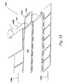
- Figure 13 shows a plurality of support apparatus secured upon a roof that comprises a plurality of substantially flat roof elements.
- Support apparatus 101 and support apparatus 1301, which is substantially similar to support apparatus 101, are shown mounted to a roof, generally indicated at 1302.
- the roof comprises a plurality of substantially flat roof elements 1303.
- a plurality of roof elements 1303 are laid in a first row 1304.
- Support apparatus 1301 extends to overlap upper portions of the first row 1304 of roof elements 1303.
- Support apparatus 101 is arranged to extend to overlap an upper portion of support apparatus 1301.
- a second row 1305 of roof elements 1303 is arranged to extend to overlap an upper portion of support apparatus 101.
- Side columns, such as column 1306 of roof elements 1303, are provided alongside each edge of the support apparatus. Roof elements in columns may be arranged to overlap side portions of a support apparatus.
- a substantially planar solar energy collection device such as device 103
- the support apparatus provides for the substantially planar solar energy collection device to be integrated within a roof in a substantially flush arrangement relative to the roof elements of the remainder of the roof. This feature contributes to the weathertightness of the support apparatus in use; reducing the effects of wind and rain upon the support apparatus and the received solar energy collection device.
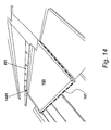
- Figure 14 shows support apparatus 101 located within a roof.
- back plate 201 defines a channel, indicated at 1401.
- Channel 1401 extends along back portion 201 such that it is oriented to run substantially in the direction of the top edge of a received solar energy collection device, such as solar energy collection device 103.
- Channel 1401 functions to direct any water that enters the apparatus and feeds up through capillary action over overlying tile to run along the channel to the sides of the support apparatus to flow away down the sides of the support apparatus.
- the channel hence encourages water run off.
- the channel may serve to strengthen the back portion.
- the side portions of support apparatus 101 are configured to encourage water run off, by for example the provision of further channels.
- FIG 15 shows the arrangement of Figure 14 , however, in Figure 15 front portion 203 of support apparatus 101 is shown removed from the remainder of the frame. It is thus to be appreciated that in use, support apparatus 101 is secured to a roof batten, such as roof batten 1501, by means of attachment of back plate 201 to the roof batten. Front portion 203 is releasably attachable to first and second side portions 206, 207 such that when the support apparatus is in use, the front portion may be removed to allow access to solar energy collection device, such as solar energy collection device 103. If desired, front portion 203 may be removed from side portions 206, 207 to allow substantially planar solar energy collection device 103 to be removed from the roof and replaced by a substitute solar energy collection device.
- the support apparatus described herein thus provides a convenient way of securing a substantially planar solar energy collection device within a roof comprising substantially flat roof elements that also allows convenient access to a secured substantially planar solar energy collection device.
- the back portion may be provided as two separate parts that are connected together by a mechanical fixing or by welding.
- the back portion is made as a single piece.
- Other of the front portion and side portions may have either construction.
- the front portion and side portions may be made from a metal, such as aluminium.
- each side portion is configured to be releasably attached to the back portion in addition to the front portion.
- Each of the side portions and the front portion may present a perimeter wall that is formed by bending a substantially planar element to provide a front wall and a back wall between which the perimeter wall extends.
Landscapes
- Engineering & Computer Science (AREA)
- Chemical & Material Sciences (AREA)
- Physics & Mathematics (AREA)
- Life Sciences & Earth Sciences (AREA)
- Sustainable Development (AREA)
- Sustainable Energy (AREA)
- Thermal Sciences (AREA)
- Combustion & Propulsion (AREA)
- Mechanical Engineering (AREA)
- General Engineering & Computer Science (AREA)
- Civil Engineering (AREA)
- Structural Engineering (AREA)
- Architecture (AREA)
- Roof Covering Using Slabs Or Stiff Sheets (AREA)
Abstract
Description
- This application claims priority from United Kingdom Patent Application No.
07 16 079.9, filed 17 August 2007 , the whole contents of which are incorporated herein by reference in their entirety. - The present invention relates to apparatus for, and a method of, supporting a substantially planar solar energy collection device on a roof, the roof comprising a plurality of roof battens and a plurality of substantially flat roof elements.
- It is known to provide a roof structure with a solar energy collecting panel. In some applications, the solar energy collecting panel is mounted upon a roof structure covering. In other applications, the solar energy collecting panel is mounted as part of a roof structure covering.
- Some roof elements are substantially flat, such as slate roof tiles. It is desirable to provide a roof comprising a plurality of roof battens and a plurality of substantially flat roof elements with a substantially planar solar energy collection device. However, a problem exists in achieving satisfactory inclusion of a substantially planar solar energy collection device within a roof comprising substantially flat roof elements.
- According to an aspect of the present invention, there is provided apparatus for supporting a substantially planar solar energy collection device on a roof, said roof comprising a plurality of roof battens and a plurality of substantially flat roof elements, comprising: a back portion configured to be secured to a roof batten and comprising a flange for locating said back portion on a roof batten, a front portion configured to receive an edge of said substantially planar solar energy collection device and defining a plurality of apertures in a front perimeter wall for allowing ventilation and water run off, and a first side portion and a second side portion configured to extend from said back portion and to be releasably secured to said front portion; said back portion, said front portion said first side portion and said second side portion are configurable to provide a frame for surrounding said substantially planar solar energy collection device and said frame is securable to said roof by securing said back portion to a roof batten, and said frame is configured such that said front portion is releasable from said first side portion and said second side portion) when said frame is secured to a roof batten.
- According to a further aspect of the present invention, there is provided a method of supporting a substantially planar solar energy collection device on a roof, said roof comprising a plurality of roof battens and a plurality of substantially flat roof elements, comprising the steps of: receiving frame apparatus comprising a back portion configured to be secured to a roof batten and comprising a flange for locating said back portion on a roof batten, a front portion configured to receive an edge of said substantially planar solar energy collection device and defining a plurality of apertures in a front perimeter wall for allowing ventilation and water run off, and a first side portion and a second side portion configured to extend from said back portion and to be releasably secured to said front portion, configuring said frame apparatus to provide a frame surrounding said substantially planar solar energy collection device, and securing said frame to said roof by securing said back portion to a roof batten.
-
-
Figure 1 shows support apparatus, in use, supporting a substantially planar solar energy collection device on a roof; -
Figure 2 shows support apparatus; -
Figure 3 shows the support apparatus ofFigure 2 located relative to a roof batten; -
Figure 4 shows the support apparatus ofFigure 2 located relative to a roof batten and with a front portion removed; -
Figure 5 shows features of a front portion of support apparatus; -
Figure 6 shows a further example of support apparatus; -
Figure 7 shows an adjustable edge of the support apparatus ofFigure 6 , in a first configuration; -
Figure 8 shows an adjustable edge of the support apparatus ofFigure 6 positioned relative to a substantially flat roof element; -
Figure 9 shows an adjustable edge of the support apparatus ofFigure 6 , in a second configuration and positioned relative to a similar adjustable edge in a similar configuration; -
Figure 10 shows a liner element located relative to a roof batten; -
Figure 11 shows a liner element located relative to a roof batten and a substantially flat roof element; -
Figure 12 shows support apparatus located relative to a liner element and a substantially flat roof element; -
Figure 13 illustrates support apparatus incorporated within a roof, the roof comprising a plurality of substantially flat roof elements; -
Figure 14 shows features of a back portion of support apparatus; and -
Figure 15 shows the support apparatus ofFigure 14 located relative to a roof batten and with a front portion removed. -
Figure 1 shows a substantially planar solar energy collection device supported on a roof by support apparatus.Support apparatus 101 is shown fitted onroof 102. The support apparatus is configured to provide a frame surrounding a substantially planar solarenergy collection device 103. The roof structure comprises a plurality of roof battens (not shown in this Figure) and a plurality of substantially flat roof elements, such asroof element 104. In this example, substantially planar solarenergy collection device 103 is a photo-voltaic device but in alternative applications the solar energy collection device may be an alternative type of device. - The substantially flat roof elements may be any suitable roofing materials. In an application, the substantially flat roof elements are slates, which may be cut from natural slate or fabricated from slate-like material such as fibre cements. In an application, the substantially flat roof elements have the approximate dimensions of 600mm x 300mm, however, in alternative embodiments the dimensions may vary. In an example, the support apparatus is suitable for use with substantially flat roof elements having a thickness of between approximately 4mm and 10mm, but in alternative examples this may vary.
- In the arrangement shown in
Figure 1 ,support apparatus 101 is located to cover a central portion of theroof 102. The support apparatus may be located to cover a different region of the roof, however, it is to be appreciated that it may be desirable to space a solar energy collection device away from the edges of the roof. - In an example, the support apparatus is configured to be laid in-line, known as non broken-bond, as shown in
Figure 1 . In an inline arrangement, a first support apparatus is aligned with a second support apparatus that is located above or below the first support apparatus. In an alternative example, the support apparatus is configured to be laid offset, known as broken-bond. In an offset arrangement, a first support apparatus is offset with a second support apparatus that is located above or below the first support apparatus. - In an application,
support apparatus 101 has awidth dimension 105 that is substantially equal to thelength dimension 106 ofroof element 104. In an alternative application,support apparatus 101 has awidth dimension 105 that is greater than thelength dimension 106 ofroof element 104. In such an application, it is possible to increase the length dimension of theroof element 104 through use of an extender clip (not shown) so as to provide a suitable headlap. An extender clip may be fabricated from a plastics material or any other suitable material. -
Support apparatus 101 is shown in further detail inFigure 2 .Support apparatus 101 comprises aback portion 201 configured to be secured to a roof batten (not shown in this Figure) and comprising aflange 202 for locating the back portion on a roof batten.Support apparatus 101 comprises afront portion 203 configured to receive an edge of a substantially planar solar energy collection device and defining a plurality of apertures, such asaperture 204, in afront perimeter wall 205. These apertures are provided for allowing ventilation and water run off.Support apparatus 101 further comprises afirst side portion 206 and asecond side portion 207, each configured to extend from theback portion 201 and to be releasably secured to thefront portion 203.Back portion 201,front portion 203 and the first andsecond side portions energy collection device 103 and that is securable to a roof by securing theback portion 201 to a roof batten.Support apparatus 101 is configured such that thefront portion 203 is releasable from thefirst side portion 206 and thesecond side portion 207 when the support apparatus is secured to a roof batten. - In an example,
front portion 203 defines a fixing aperture at each end, such asaperture 208, for allowingfront portion 203 to be releasably secured to thefirst side portion 206 and thesecond side portion 207 by means of a mechanical fixing. The releasable mechanical fixing may be comprise a bolt, such asbolt 209, a screw, a pin or a clamp device. However, any suitable device to provide a releasable attachment between thefront portion 203 and theside portions -
Figure 3 showssupport apparatus 101 located relative to a roof batten 301. Roof batten 301 forms part of a sloping roof.Flange 202 is provided to the rear of the back portion. In use,flange 202 extends down along the side of the roof batten that faces towards the sky, such that the back portion in effect is hooked over the roof batten, such that the remainder of the back portion extends over the roof batten towards the ground.Back portion 201 defines a plurality of apertures, such asaperture 302, for allowingsupport apparatus 101 to be secured to a roof batten by means of a mechanical fixing, for example a bolt, a screw or any other suitable device. In an example, fixing apertures are slightly oval in shape to allow for thermal expansion. The back portion may be fabricated from a metal, such as aluminium. - As shown in
Figure 3 , a side portion may be provided with a plurality of apertures. In this example, both side portions define a plurality of apertures, such asaperture 303, in a side perimeter wall, such asside perimeter wall 304 ofsecond side portion 207. These apertures facilitate ventilation and water run off. - As shown in
Figure 4 , whensupport apparatus 101 is secured relative to a roof batten, such as roof batten 301,front portion 203 is releasable from the first andsecond side portions front portion 203 is removed from the remainder of the frame, the back portion and side portions of the frame remains secured to the roof batten and hence the roof. In turn, a received solar energy collection device is held on the roof by the back portion and side portions. - The ability to remove
front portion 203 from the secured support apparatus enables maintenance and/or replacement of a solar energy collection device supported within the frame of the support apparatus, such asdevice 103, as required. This allows maintenance to be performed without the need to remove surrounding roof elements from the roof. In this way, undesirable disturbance of surrounding roof elements is avoided. This is particularly advantageous when dealing with slates that are of a fragile nature. - Further features of the front portion are illustrated in
Figure 4 .Front portion 203 is configured to receive a substantially planar solar energy collection device in an arrangement in which a gap is provided underneath the solar energy collection device for allowing ventilation.Front portion 203 is configured to receive a substantially planar solar energy collection device in an arrangement in which a gap is provided between the received edge of the substantially planar solar energy collection device and saidfront perimeter wall 205. Again this feature serves to facilitate ventilation. - In an example,
front portion 203 comprises at least onesupport brace 401 that presents a step, as indicated inregion 402, onto which a solar energy collection device may be located. The support brace is configured to receive a substantially planar solar energy collection device such that the solar energy collection device extends in a plane that is held away from any planar regions of the support apparatus and roof. In this way, the solar energy collection material is maintained at a position that is displaced from thebottom 403 of the frame and the lower end of the frame, in this examplefront perimeter wall 205. In addition to improving ventilation paths around a received solar energy collection device, this arrangement also serves to allow water run off to prevent pooling. In alternative examples, any component or profile that achieves the provision of ventilation and water run off space around a received solar energy collection device may be used. -
Figure 5 shows features of a front portion in further detail. As previously described,front portion 203 defines a plurality of apertures in afront perimeter wall 205. In an embodiment, a first row ofapertures 501 is defined byfront perimeter wall 205. In addition, the front portion defines a second row ofapertures 502 in thefront perimeter wall 205 and the apertures in thesecond row 502 are offset from the apertures in the first row. This offsetting of apertures allows air to circulate whilst reducing the risk of water entering the apparatus. Allowing air to circulate underneath a located solar energy collection device reduces the risk of degradation of the material used for solar energy collection and also serves to cool the solar energy collection device in order to avoid invalidating any warranties associated with the solar energy collection device. - The front portion the support apparatus may also present at least one clamping region, such as clamping
region 503, for allowing a solar energy collection device to be connected to the front portion. In an application a connection between a solar energy collection device and a front portion is provided by means of a clip, although in alternative applications other fixing devices may be utilised. -
Figure 6 shows support apparatus for supporting a substantially planar solar energy collection device on a roof, the roof comprising a plurality of roof battens and a plurality of substantially flat roof elements.Support apparatus 601 comprises aback portion 602 configured to be secured to a roof batten and comprising a flange for locating the back portion on a roof batten.Support apparatus 601 comprises afront portion 603 configured to receive an edge of a substantially planar solar energy collection device and defining a plurality of apertures (not shown) for allowing ventilation and water run off. Afirst side portion 604 and asecond side portion 605 are provided that are configured to extend from theback portion 602 and to be releasably secured to thefront portion 603. In a similar manner to supportapparatus 101,support apparatus 601 provides a frame for surrounding a substantially planar solar energy collection device that is securable to the roof by securing the back portion to a roof batten.Support apparatus 101 is also similarly configured to allow thefront portion 603 to be released from the first andsecond side portions - In this example,
first side portion 604 andsecond side portion 605 ofsupport apparatus 601 each present an adjustable edge. In a first configuration, each adjustable edge is configured to be positioned against a roofing element and in a second configuration, each adjustable edge is configured to be positioned against a similar edge. The adjustable edge feature is described in further detail below. -
Back portion 602 defines a substantially planar region for receiving a portion of a substantially flat roof element. The back portion comprises a hole, such ashole 606 for receiving a cable passed through for linking adjacent solar energy collection devices together. This feature acts as an aid when the support apparatus is being installed. Each solar energy collection device mounted on a roof will have one or more cables attached thereto. When a solar energy collection device is in the process of being mounted to a roof,hole 606 allows an associated cable to be held proud so that it does not become caught under a solar energy collection device.Hole 606 therefore provides for easy location of a cable for appropriate connection. -
Figure 7 illustrates the cross-section of an adjustable edge, such as that provided byfirst side portion 604. The adjustable edge comprises afirst plate 701 and asecond plate 702, which extend substantially parallel to each other. However,plate 701 extends beyond the ends ofplate 702. A connectingwall 703 extends substantially perpendicularly betweenplate 701 andplate 702 and presents ahook portion 704. Anotch 705 is provided inplate 701 substantially at the position of the free end of thehook portion 704.Adjustable edge 604 is configurable from the first configuration, in which the adjustable edge is configured to be positioned against a roofing element, into the second configuration, in which the adjustable edge is configured to be positioned against a similar edge, by the removal of anextension portion 706 of the adjustable edge. The extension portion extends from one side ofnotch 705. Thus, notch 705 is provided along a predetermined line that delineates the fixed end of theextension portion 706 and facilitates the removal ofportion 706 of the adjustable edge. - In an example, each adjustable edge is made from a plastics material, such as ASA, or a metal, such as aluminium. The adjustable edges may be produced by an extrusion process.
- In this illustrated example, notch 705, has a V-shaped cross-section to concentrate stress when pressure is applied to
plate 701 in order to break it. It is to be appreciated that the amount of force required to snapplate 701 along the line ofnotch 705 may vary between applications depending upon the construction of theplate 701 and the material of fabrication. It is to be appreciated thatplate 701 may require a plurality of bending operations in each direction aboutnotch 705 before separation of theextension portion 706 is achieved. A tool, such as a knife, may be used along the notch to facilitate the removal process. - In this example, a
cylindrical channel 707 is presented, which is provided by protrusions projecting fromplate 701.Cylindrical channel 604 is configured to receive a fixing element, such as a self-tapping screw, to allow attachment, detachment and reattachment of a front portion. - In
Figure 8 ,adjustable edge 604 is shown, in use, in the first configuration, in which the adjustable edge is configured to be positioned against a roofing element. Thus, it can be seen thatadjustable edge 604 still hasportion 706 in tact.Hook portion 704 is shown abutting against a substantially flat roof element, such asslate 104. In this shown arrangement,roof element 104 sits uponportion 706 ofplate 701. - A
first ridge 801 and asecond ridge 802 are shown, which are provided alongplate 701 to elevateslate 104 in order to provide a space betweenslate 104 and the main body ofportion 706. This feature serves to break capillary action. Theridges -
Figure 9 showsadjustable edge portion 604 positioned alongside asimilar edge portion 901. Bothadjustable edge portions adjustable edge portion 604 ofFigure 7 , this may be achieved by snapping offextension portion 706 atnotch 705 shown inFigure 7 . - In the arrangement shown in
Figure 9 , the twoedges Channel element 902 has a substantially U-shaped cross-section and is configured to be located betweenhook portion 704 ofadjustable edge 604 andhook portion 903 ofadjustable edge 902. The channel element serves to fix theadjustable edges channel piece 902 provides a dual functionality in that it provides a locking detail between the two adjacent edges and also provides a weatherproof element that extends between the adjacent edges. Thus, the channel element provides a degree of weatherproofness at the join. -
Figure 10 shows a further element of support apparatus. The support apparatus may comprise at least one liner tray having a flange for locating the liner tray on a roof batten. In a typical application, a plurality of liner trays are provided and utilised. In an example, a liner tray is fabricated from a metal. However, the liner tray may be fabricated from any water impermeable material.Liner tray 1001, also known as a soak tray, has aflange 1002 for locating the liner tray on a roof batten. InFigure 10 , liner tray is shown located on roof batten 1003.Flange 1002 ofliner tray 1001 is configured to locate the liner tray relative to a roof batten in a similar fashion to flange 202 ofback portion 201 of support apparatus 101 (detailed inFigure 2 ). Thus, the support apparatus provides similar elements that have similar associated methods of use and hence the support apparatus is intuitive to install. - As shown in
Figure 11 , onceliner tray 1001 is located with respect to a roof batten, such as roof batten 1003, substantially flat roof elements, such asroof element 1101, may be placed on top of the locatedliner tray 1001. A roof element may be placed on top of a located liner tray in an arrangement in which the roof element fully or partially covers the main surface area of the liner tray. Each liner tray acts to direct any water that falls onto the liner tray to run off, and so serves to protect any damage to the roof due to the prolonged presence of water. - As illustrated in
Figure 12 , a liner tray, such asliner tray 1001, serves to provide an interface between a support apparatus, such assupport apparatus 101, and roof elements, such asroof elements 1201. By positioning liner trays all around the perimeter ofsupport apparatus frame 101, a watertight edging is effectively provided. It is to be appreciated that use of the liner tray provides an interface between the support apparatus and the roof elements, and provides a degree of flexibility that enables the support apparatus to be used on a roof that comprises roof elements having various dimensions. -
Figure 13 shows a plurality of support apparatus secured upon a roof that comprises a plurality of substantially flat roof elements.Support apparatus 101 andsupport apparatus 1301, which is substantially similar tosupport apparatus 101, are shown mounted to a roof, generally indicated at 1302. The roof comprises a plurality of substantiallyflat roof elements 1303. In the shown arrangement, a plurality ofroof elements 1303 are laid in afirst row 1304.Support apparatus 1301 extends to overlap upper portions of thefirst row 1304 ofroof elements 1303.Support apparatus 101 is arranged to extend to overlap an upper portion ofsupport apparatus 1301. Asecond row 1305 ofroof elements 1303 is arranged to extend to overlap an upper portion ofsupport apparatus 101. Side columns, such ascolumn 1306 ofroof elements 1303, are provided alongside each edge of the support apparatus. Roof elements in columns may be arranged to overlap side portions of a support apparatus. - Thus, a substantially planar solar energy collection device, such as
device 103, may be supported within a roof by the described support apparatus. The support apparatus provides for the substantially planar solar energy collection device to be integrated within a roof in a substantially flush arrangement relative to the roof elements of the remainder of the roof. This feature contributes to the weathertightness of the support apparatus in use; reducing the effects of wind and rain upon the support apparatus and the received solar energy collection device. -
Figure 14 showssupport apparatus 101 located within a roof. In an example, backplate 201 defines a channel, indicated at 1401.Channel 1401 extends alongback portion 201 such that it is oriented to run substantially in the direction of the top edge of a received solar energy collection device, such as solarenergy collection device 103.Channel 1401 functions to direct any water that enters the apparatus and feeds up through capillary action over overlying tile to run along the channel to the sides of the support apparatus to flow away down the sides of the support apparatus. The channel hence encourages water run off. In addition, the channel may serve to strengthen the back portion. - In an example, the side portions of
support apparatus 101 are configured to encourage water run off, by for example the provision of further channels. -
Figure 15 shows the arrangement ofFigure 14 , however, inFigure 15 front portion 203 ofsupport apparatus 101 is shown removed from the remainder of the frame. It is thus to be appreciated that in use,support apparatus 101 is secured to a roof batten, such as roof batten 1501, by means of attachment ofback plate 201 to the roof batten.Front portion 203 is releasably attachable to first andsecond side portions energy collection device 103. If desired,front portion 203 may be removed fromside portions energy collection device 103 to be removed from the roof and replaced by a substitute solar energy collection device. The support apparatus described herein thus provides a convenient way of securing a substantially planar solar energy collection device within a roof comprising substantially flat roof elements that also allows convenient access to a secured substantially planar solar energy collection device. - It is to be appreciated that specific arrangements of components of the described support apparatus may vary between examples. For example, the back portion may be provided as two separate parts that are connected together by a mechanical fixing or by welding. Alternatively, the back portion is made as a single piece. Other of the front portion and side portions may have either construction. The front portion and side portions may be made from a metal, such as aluminium. In an example, each side portion is configured to be releasably attached to the back portion in addition to the front portion. Each of the side portions and the front portion may present a perimeter wall that is formed by bending a substantially planar element to provide a front wall and a back wall between which the perimeter wall extends.
Claims (20)
- Apparatus (101) for supporting a substantially planar solar energy collection device (103) on a roof (102), said roof comprising a plurality of roof battens (301) and a plurality of substantially flat roof elements (104), comprising:a back portion (201) configured to be secured to a roof batten (301) and comprising a flange (202) for locating said back portion on a roof batten (301),a front portion (203) configured to receive an edge of said substantially planar solar energy collection device (103) and defining a plurality of apertures (204) in a front perimeter wall (205) for allowing ventilation and water run off, anda first side portion (206) and a second side portion (207) configured to extend from said back portion (201) and to be releasably secured to said front portion (203);said back portion (201), said front portion (203) said first side portion (206) and said second side portion (207) are configurable to provide a frame for surrounding said substantially planar solar energy collection device (103) and said frame is securable to said roof (102) by securing said back portion (201) to a roof batten (301), andsaid frame is configured such that said front portion (203) is releasable from said first side portion (206) and said second side portion (207) when said frame is secured to a roof batten (301).
- Apparatus according to claim 1, wherein said first side portion (206) and said second side portion (207) each defines a plurality of apertures (303) in a side perimeter wall (304) for allowing ventilation and water run off.
- Apparatus according to claim 1, wherein said front portion (203) defines a first row of apertures (501) and a second row of apertures (502) in said front perimeter wall (205) and the apertures in said second row (502) are offset from the apertures in said first row (501).
- Apparatus according to claim 1, wherein said first side portion (604) and said second side portion (605) each present an adjustable edge such that:in a first configuration said adjustable edge is configured to be positioned against a roofing element; andin a second configuration said adjustable edge is configured to be positioned against a similar edge.
- Apparatus according to claim 4, wherein each said adjustable edge (604, 605) is configurable from said first configuration into said second configuration by the removal of an extension portion (706) of said adjustable edge.
- Apparatus according to claim 5, wherein each said adjustable edge (604, 605) is provided with a notch (705) along a predetermined line to facilitate removal of said extension portion (706) of said adjustable edge.
- Apparatus according to claim 4, wherein each said adjustable edge (604, 605) is fabricated from a plastics material.
- Apparatus according to claim 4, wherein each said adjustable edge (604, 605) is fabricated from aluminium.
- Apparatus according to claim 4, further comprising a channel element (902) configured to be extend between two adjacent adjustable edges (604, 605).
- Apparatus according to claim 1, further comprising at least one liner tray (1001) having a flange (1002) for locating said liner tray on a roof batten (1003).
- Apparatus according to claim 1, wherein said front portion (203) is configured to receive said substantially planar solar energy collection device (103) in an arrangement in which a gap is provided underneath said substantially planar solar energy collection device (103) for allowing ventilation.
- Apparatus according to claim 1, wherein said front portion (203) is configured to receive said substantially planar solar energy collection device in an arrangement in which a gap is provided between the received edge of said substantially planar solar energy (103) collection device and said front perimeter wall (205).
- Apparatus according to claim 1, wherein said back portion (201) defines a substantially planar region for receiving a portion of a substantially flat roof element.
- Apparatus according to claim 1, wherein said substantially planar solar energy collection device (103) is a photo-voltaic device.
- Apparatus according to claim 1, wherein said plurality of substantially flat roof elements (104) comprises slates that are cut from natural slate or fabricated from slate-like material.
- Apparatus according to claim 1, wherein said back portion (201) comprises a hole (606) for receiving a cable passed through for linking adjacent solar energy collection devices together.
- A method of supporting a substantially planar solar energy collection device (103) on a roof (102), said roof comprising a plurality of roof battens (301) and a plurality of substantially flat roof elements (104), comprising the steps of:receiving frame apparatus (101) comprising a back portion (201) configured to be secured to a roof batten (301) and comprising a flange (202) for locating said back portion (201) on a roof batten (301),a front portion (203) configured to receive an edge of said substantially planar solar energy collection device (103) and defining a plurality of apertures (204) in a front perimeter wall (205) for allowing ventilation and water run off, anda first side portion (206) and a second side portion (207) configured to extend from said back portion (201) and to be releasably secured to said front portion (203),configuring said frame apparatus (101) to provide a frame surrounding said substantially planar solar energy collection device (103), andsecuring said frame to said roof (102) by securing said back portion (201) to a roof batten (301).
- A method according to claim 17, further comprising the steps of:releasing said front portion (203) from said first side portion (206) and said second side portion (207) when said frame is secured to a roof batten (301).
- A method according to claim 17, further comprising the steps of:locating a substantially planar solar energy collection device (103) between said back portion (201), said first side portion (206) and said second side portion (207), andsecuring said front portion (203) to said first side portion (206) and said second side portion (207).
- A method according to claim 17, wherein said substantially planar solar energy collection device (103) is a photo-voltaic device.
Applications Claiming Priority (1)
| Application Number | Priority Date | Filing Date | Title |
|---|---|---|---|
| GB0716079A GB2454162A (en) | 2007-08-17 | 2007-08-17 | Support apparatus for supporting solar energy collection devices |
Publications (2)
| Publication Number | Publication Date |
|---|---|
| EP2026017A2 true EP2026017A2 (en) | 2009-02-18 |
| EP2026017A3 EP2026017A3 (en) | 2016-07-06 |
Family
ID=38566562
Family Applications (1)
| Application Number | Title | Priority Date | Filing Date |
|---|---|---|---|
| EP08252700.3A Withdrawn EP2026017A3 (en) | 2007-08-17 | 2008-08-14 | Support apparatus for supporting a solar energy collection device |
Country Status (3)
| Country | Link |
|---|---|
| US (1) | US20090044850A1 (en) |
| EP (1) | EP2026017A3 (en) |
| GB (1) | GB2454162A (en) |
Cited By (6)
| Publication number | Priority date | Publication date | Assignee | Title |
|---|---|---|---|---|
| EP2426430A1 (en) | 2010-09-01 | 2012-03-07 | Solar Century Holdings Limited | A roof |
| FR2965830A1 (en) * | 2010-10-11 | 2012-04-13 | Dan Bog | System for integration of photovoltaic modules in roof, has photovoltaic modules obtained by fixation of active surface within frame to allow assembly to serve as covering element by combination of frame elements |
| FR2975174A1 (en) * | 2011-05-10 | 2012-11-16 | 3I Plus | Plastic molded frame for use in tile fixed on support of building to receive photovoltaic panel, has groove opened toward peripheral center of frame such that part of circumference of panel is formed between wings, where groove holds panel |
| CN105143784A (en) * | 2013-02-28 | 2015-12-09 | 太阳能科技瑞典公司 | Light absorbing unit integrated in a roof construction |
| WO2017058084A1 (en) * | 2015-09-30 | 2017-04-06 | Soltech Energy Sweden Ab | Solar cell module |
| WO2017058086A1 (en) * | 2015-09-30 | 2017-04-06 | Soltech Energy Sweden Ab | Solar cell module |
Families Citing this family (73)
| Publication number | Priority date | Publication date | Assignee | Title |
|---|---|---|---|---|
| NL1028379C2 (en) * | 2005-02-23 | 2006-08-24 | Girasol Internat B V | Device and method for fixing objects, in particular solar panels, on a roof. |
| ES2372737B1 (en) * | 2009-09-17 | 2013-01-24 | Provif Energías Renovables, S.A. | FRAME FOR SOLAR FOLLOWERS. |
| SG170625A1 (en) * | 2009-10-13 | 2011-05-30 | Alternative Energy Technology Pte Ltd | Photovoltaic cell support assembly |
| US8915030B2 (en) * | 2009-10-22 | 2014-12-23 | Dow Global Technologies Llc | Direct mounted photovoltaic device with improved adhesion and method thereof |
| US9316416B2 (en) * | 2010-10-27 | 2016-04-19 | Gottlieb Binder Gmbh & Co. Kg | Panel arrangement with clamping clip |
| US9602046B2 (en) * | 2010-12-17 | 2017-03-21 | Dow Global Technologies Llc | Photovoltaic device |
| US20120216853A1 (en) * | 2011-02-25 | 2012-08-30 | Rountree John | Integrated solar energy system |
| CA2739766C (en) * | 2011-05-10 | 2016-08-23 | Robert Richardson | Roof solar panel for conventional sloping roof and shingle integration |
| US10361652B2 (en) * | 2015-09-14 | 2019-07-23 | Vivint Solar, Inc. | Solar module mounting |
| US11012024B2 (en) | 2018-07-03 | 2021-05-18 | Building Materials Investment Corporation | Roof integrated photovoltaic system with improved serviceability |
| US11543155B2 (en) * | 2019-02-15 | 2023-01-03 | Gregory S. Daniels | Devices and systems for ventilation of solar roofs |
| WO2021108403A1 (en) | 2019-11-27 | 2021-06-03 | GAF Energy LLC | Roof integrated photovoltaic module with spacer |
| US11398795B2 (en) | 2019-12-20 | 2022-07-26 | GAF Energy LLC | Roof integrated photovoltaic system |
| WO2021150763A1 (en) | 2020-01-22 | 2021-07-29 | GAF Energy LLC | Integrated photovoltaic roofing shingles, methods, systems, and kits thereof |
| WO2021168126A1 (en) | 2020-02-18 | 2021-08-26 | GAF Energy LLC | Photovoltaic module with textured superstrate providing shingle-mimicking appearance |
| EP4111507A4 (en) | 2020-02-27 | 2024-03-27 | Gaf Energy LLC | PHOTOVOLTAIC MODULE WITH LIGHT-DIFFUSING ENCAPSULATION AGENT PROVIDING A SHINGLE-LIKE APPEARANCE |
| US11961928B2 (en) | 2020-02-27 | 2024-04-16 | GAF Energy LLC | Photovoltaic module with light-scattering encapsulant providing shingle-mimicking appearance |
| CA3174671A1 (en) | 2020-04-09 | 2021-10-14 | GAF Energy LLC | Three-dimensional laminate photovoltaic module |
| CA3175818A1 (en) | 2020-04-30 | 2021-11-04 | Alexander SHARENKO | Photovoltaic module frontsheet and backsheet |
| WO2021230938A1 (en) | 2020-05-13 | 2021-11-18 | GAF Energy LLC | Electrical cable passthrough |
| CN115769383A (en) | 2020-06-04 | 2023-03-07 | Gaf能源有限责任公司 | Photovoltaic roof panel and method of installation |
| WO2022020490A1 (en) | 2020-07-22 | 2022-01-27 | GAF Energy LLC | Photovoltaic modules |
| CA3188361A1 (en) | 2020-08-11 | 2022-02-17 | Richard Perkins | Roof mounted photovoltaic system and method for wireless transfer of electrical energy |
| EP4208902A4 (en) | 2020-09-03 | 2024-11-06 | Gaf Energy LLC | BUILDING-INTEGRATED PHOTOVOLTAIC SYSTEM |
| US11545928B2 (en) | 2020-10-13 | 2023-01-03 | GAF Energy LLC | Solar roofing system |
| US11444569B2 (en) | 2020-10-14 | 2022-09-13 | GAF Energy LLC | Mounting apparatus for photovoltaic modules |
| US11454027B2 (en) | 2020-10-29 | 2022-09-27 | GAF Energy LLC | System of roofing and photovoltaic shingles and methods of installing same |
| WO2022103968A1 (en) | 2020-11-12 | 2022-05-19 | GAF Energy LLC | Roofing shingles with handles |
| WO2022103841A1 (en) | 2020-11-13 | 2022-05-19 | GAF Energy LLC | Photovoltaic module systems and methods |
| US11996797B2 (en) | 2020-12-02 | 2024-05-28 | GAF Energy LLC | Step flaps for photovoltaic and roofing shingles |
| WO2022159478A1 (en) | 2021-01-19 | 2022-07-28 | GAF Energy LLC | Watershedding features for roofing shingles |
| US11496088B2 (en) | 2021-02-19 | 2022-11-08 | GAF Energy LLC | Photovoltaic module for a roof with continuous fiber tape |
| US12568694B2 (en) | 2021-03-19 | 2026-03-03 | GAF Energy LLC | Photovoltaic module with a laminated potted printed circuit board |
| MX2023011156A (en) | 2021-03-29 | 2023-10-05 | GAF Energy LLC | Electrical components for photovoltaic systems. |
| WO2022236029A1 (en) | 2021-05-06 | 2022-11-10 | GAF Energy LLC | Photovoltaic module with transparent perimeter edges |
| CA3215217A1 (en) | 2021-06-02 | 2022-12-08 | Richard Perkins | Photovoltaic module with light-scattering encapsulant providing shingle-mimicking appearance |
| WO2023275629A1 (en) * | 2021-06-29 | 2023-01-05 | Arka Energy Inc. | System for mounting tiles over a surface |
| WO2023283248A1 (en) | 2021-07-06 | 2023-01-12 | GAF Energy LLC | Jumper module for photovoltaic systems |
| US11512480B1 (en) | 2021-07-16 | 2022-11-29 | GAF Energy LLC | Roof material storage bracket |
| US11728759B2 (en) | 2021-09-01 | 2023-08-15 | GAF Energy LLC | Photovoltaic modules for commercial roofing |
| WO2023141566A1 (en) | 2022-01-20 | 2023-07-27 | GAF Energy LLC | Roofing shingles for mimicking the appearance of photovoltaic modules |
| US12013153B2 (en) | 2022-02-08 | 2024-06-18 | GAF Energy LLC | Building integrated photovoltaic system |
| WO2023164494A1 (en) | 2022-02-23 | 2023-08-31 | GAF Energy LLC | Roofing shingle and method of manufacturing same |
| WO2023173019A1 (en) | 2022-03-10 | 2023-09-14 | GAF Energy LLC | Combined encapsulant and backsheet for photovoltaic modules |
| WO2023197010A1 (en) | 2022-04-08 | 2023-10-12 | GAF Energy LLC | Low profile connector for solar roofing systems |
| WO2023240005A1 (en) | 2022-06-06 | 2023-12-14 | GAF Energy LLC | Active component indicators for photovoltaic systems |
| CA3258720A1 (en) | 2022-07-15 | 2024-01-18 | GAF Energy LLC | Solar roofing system with fiber composite roofing shingles |
| CA3264095A1 (en) | 2022-08-24 | 2024-02-29 | GAF Energy LLC | System for forming a roofing membrane, and associated method |
| EP4581684A1 (en) | 2022-08-29 | 2025-07-09 | Gaf Energy LLC | Photovoltaic modules with offset layers |
| CA3266474A1 (en) | 2022-09-01 | 2024-03-07 | GAF Energy LLC | Anti-reflective photovoltaic shingles and related methods |
| WO2024059462A1 (en) | 2022-09-13 | 2024-03-21 | GAF Energy LLC | Sensing roofing system and method thereof |
| US12015374B2 (en) | 2022-09-26 | 2024-06-18 | GAF Energy LLC | Photovoltaic modules integrated with building siding and fencing |
| US12143064B2 (en) | 2022-09-29 | 2024-11-12 | GAF Energy LLC | Jumper module with sleeve |
| US12031332B2 (en) | 2022-10-25 | 2024-07-09 | GAF Energy LLC | Roofing materials and related methods |
| EP4591429A1 (en) | 2022-10-27 | 2025-07-30 | Gaf Energy LLC | Building integrated photovoltaic systems |
| US12413183B2 (en) | 2022-11-15 | 2025-09-09 | GAF Energy LLC | Electrical cable passthrough for photovoltaic systems |
| US11811361B1 (en) | 2022-12-14 | 2023-11-07 | GAF Energy LLC | Rapid shutdown device for photovoltaic modules |
| US12445089B2 (en) | 2023-02-03 | 2025-10-14 | GAF Energy LLC | Photovoltaic module, and associated kit, system, and method |
| US12355390B1 (en) | 2023-02-03 | 2025-07-08 | GAF Energy LLC | Solar shingle and associated roofing system and method |
| US12413174B2 (en) | 2023-02-21 | 2025-09-09 | GAF Energy LLC | Roofing system including photovoltaic module wireway cover, and associated method |
| CA3229888A1 (en) | 2023-02-23 | 2025-04-25 | GAF Energy LLC | Photovoltaic shingles with multi-module power electronics |
| US12506440B2 (en) | 2023-02-28 | 2025-12-23 | GAF Energy LLC | Photovoltaic modules with energy storage components |
| CA3231973A1 (en) | 2023-03-14 | 2025-06-26 | GAF Energy LLC | Integrated cell and circuit interconnection |
| US12009782B1 (en) | 2023-04-04 | 2024-06-11 | GAF Energy LLC | Photovoltaic systems with wireways |
| US12413177B2 (en) | 2023-08-31 | 2025-09-09 | GAF Energy LLC | Photovoltaic modules and roofing shingles with nail zones |
| US12451838B1 (en) | 2023-10-06 | 2025-10-21 | GAF Energy LLC | Failsafe functionality for photovoltaic modules |
| WO2025090902A1 (en) | 2023-10-26 | 2025-05-01 | GAF Energy LLC | Roofing systems with water ingress protection |
| US12438495B2 (en) | 2023-12-05 | 2025-10-07 | GAF Energy LLC | Roofing system for prevention of roofing shingle deformation |
| US12480309B2 (en) | 2024-04-10 | 2025-11-25 | GAF Energy LLC | Roofing shingles with fire retardant structure |
| US12695410B2 (en) | 2024-05-06 | 2026-07-28 | GAF Energy LLC | Frontsheets for photovoltaic modules |
| WO2025240788A1 (en) | 2024-05-17 | 2025-11-20 | GAF Energy LLC | Metal roofing shingles |
| US12695411B2 (en) | 2024-07-19 | 2026-07-28 | GAF Energy LLC | Step flaps for integrating photovoltaic systems with roofing shingles |
| US12540474B2 (en) | 2024-07-22 | 2026-02-03 | GAF Energy LLC | Electrically grounding metal roofing shingles with photovoltaic systems |
Family Cites Families (15)
| Publication number | Priority date | Publication date | Assignee | Title |
|---|---|---|---|---|
| US3073235A (en) * | 1959-02-26 | 1963-01-15 | Smith | Roof ventilators |
| US4087624A (en) * | 1976-05-17 | 1978-05-02 | Hitchcock Robert A | Fire shield for electrical box |
| US4139399A (en) * | 1978-01-18 | 1979-02-13 | Solarex Corporation | Solar panel with removable cell matrix, and method of making same |
| FR2465315A1 (en) * | 1979-09-10 | 1981-03-20 | Radiotechnique Compelec | PHOTOVOLTAIC GENERATING PANEL ASSURING THE SEALING IN THE INTEMPERIES OF A ROOF BY DIRECT INSTALLATION ON THE FRAMEWORK |
| US4692557A (en) * | 1986-10-16 | 1987-09-08 | Shell Oil Company | Encapsulated solar cell assemblage and method of making |
| US5164020A (en) * | 1991-05-24 | 1992-11-17 | Solarex Corporation | Solar panel |
| JP2000027395A (en) * | 1998-07-15 | 2000-01-25 | Fujisash Co | Solar panel and its mounting structure |
| JP2001193245A (en) * | 1999-10-25 | 2001-07-17 | Matsushita Electric Works Ltd | Solar cell frame structure, solar cell tile and method of construction, and solar hot water supply system |
| JP2003027674A (en) * | 2001-07-16 | 2003-01-29 | Sanko Techno Co Ltd | Roofing material with solar panel and solar power generation roof structure |
| DE10244473B4 (en) * | 2002-09-18 | 2010-01-21 | Roto Frank Ag | Photovoltaic device with inverter and air flow cooling |
| US20040154655A1 (en) * | 2003-02-12 | 2004-08-12 | Sharp Kabushiki Kaisha | Attaching structural unit used for installing quadrangular solar-battery module onto slanted roof |
| JP4056419B2 (en) * | 2003-03-31 | 2008-03-05 | シャープ株式会社 | Solar cell unit and roof mounting method thereof |
| US7297866B2 (en) * | 2004-03-15 | 2007-11-20 | Sunpower Corporation | Ventilated photovoltaic module frame |
| CN2719970Y (en) * | 2004-07-15 | 2005-08-24 | 常州天合光能有限公司 | Photovoltaic generating roof member |
| US20060225780A1 (en) * | 2005-04-08 | 2006-10-12 | Sharp Manufacturing Company Of America, A Division Of Sharp Electronics Corporation | Rooftop photovoltaic module |
-
2007
- 2007-08-17 GB GB0716079A patent/GB2454162A/en not_active Withdrawn
-
2008
- 2008-08-13 US US12/228,530 patent/US20090044850A1/en not_active Abandoned
- 2008-08-14 EP EP08252700.3A patent/EP2026017A3/en not_active Withdrawn
Cited By (7)
| Publication number | Priority date | Publication date | Assignee | Title |
|---|---|---|---|---|
| EP2426430A1 (en) | 2010-09-01 | 2012-03-07 | Solar Century Holdings Limited | A roof |
| FR2965830A1 (en) * | 2010-10-11 | 2012-04-13 | Dan Bog | System for integration of photovoltaic modules in roof, has photovoltaic modules obtained by fixation of active surface within frame to allow assembly to serve as covering element by combination of frame elements |
| FR2975174A1 (en) * | 2011-05-10 | 2012-11-16 | 3I Plus | Plastic molded frame for use in tile fixed on support of building to receive photovoltaic panel, has groove opened toward peripheral center of frame such that part of circumference of panel is formed between wings, where groove holds panel |
| CN105143784A (en) * | 2013-02-28 | 2015-12-09 | 太阳能科技瑞典公司 | Light absorbing unit integrated in a roof construction |
| EP2972003A4 (en) * | 2013-02-28 | 2016-10-05 | Soltech Energy Sweden Ab | Light absorbing unit integrated in a roof construction |
| WO2017058084A1 (en) * | 2015-09-30 | 2017-04-06 | Soltech Energy Sweden Ab | Solar cell module |
| WO2017058086A1 (en) * | 2015-09-30 | 2017-04-06 | Soltech Energy Sweden Ab | Solar cell module |
Also Published As
| Publication number | Publication date |
|---|---|
| GB0716079D0 (en) | 2007-09-26 |
| GB2454162A (en) | 2009-05-06 |
| US20090044850A1 (en) | 2009-02-19 |
| EP2026017A3 (en) | 2016-07-06 |
Similar Documents
| Publication | Publication Date | Title |
|---|---|---|
| US20090044850A1 (en) | Support apparatus for supporting a solar energy collection device | |
| US11114577B2 (en) | Photovoltaic power generation device | |
| EP3812529B1 (en) | Rail-less roof mounting system | |
| CN102725462B (en) | Fixing member | |
| JP3475781B2 (en) | Photovoltaic module mounting rail | |
| US8701360B2 (en) | Method and apparatus for assembling photovoltaic modules | |
| EP2169139B1 (en) | Fixing structure of solar battery module, frame for the solar battery module, and fixing member | |
| JP4381634B2 (en) | Solar panel fixing device | |
| CN110892120A (en) | Side Baffle Interconnects for Photovoltaic Roof Modules | |
| CA3070451A1 (en) | Panel, assembly of panels, and associated roof | |
| JP2018137962A (en) | Side frame for solar cell module | |
| US12546348B2 (en) | Solar panel mounting configuration | |
| US20170356189A1 (en) | Tile flashing | |
| WO2011163616A1 (en) | Roof panel spacer | |
| JP2000345668A (en) | Solar cell module support device and solar cell power generation device | |
| JP3108579B2 (en) | Roofing materials for solar cells | |
| EP2921800A1 (en) | Clamping means for fastening frameless solar modules | |
| SK132998A3 (en) | Photovoltaic system for a sloping roof | |
| JP6591172B2 (en) | Installation structure of solar cell module | |
| JP2003184245A (en) | Solar cell tile snow stopper structure and snow stopper for solar cell tile | |
| JP5686771B2 (en) | Solar cell module fixing structure and solar cell module fixing method | |
| JP7668729B2 (en) | Roof covering and installation method for roofing material type solar cell module | |
| JP6192453B2 (en) | Roof structure, solar cell module fixture, solar cell module mounting structure, and solar cell module mounting method | |
| JP5601923B2 (en) | Attaching roof exterior materials | |
| CN111699626B (en) | Solar cell module and solar power generation system |
Legal Events
| Date | Code | Title | Description |
|---|---|---|---|
| PUAI | Public reference made under article 153(3) epc to a published international application that has entered the european phase |
Free format text: ORIGINAL CODE: 0009012 |
|
| AK | Designated contracting states |
Kind code of ref document: A2 Designated state(s): AT BE BG CH CY CZ DE DK EE ES FI FR GB GR HR HU IE IS IT LI LT LU LV MC MT NL NO PL PT RO SE SI SK TR |
|
| AX | Request for extension of the european patent |
Extension state: AL BA MK RS |
|
| PUAL | Search report despatched |
Free format text: ORIGINAL CODE: 0009013 |
|
| AK | Designated contracting states |
Kind code of ref document: A3 Designated state(s): AT BE BG CH CY CZ DE DK EE ES FI FR GB GR HR HU IE IS IT LI LT LU LV MC MT NL NO PL PT RO SE SI SK TR |
|
| AX | Request for extension of the european patent |
Extension state: AL BA MK RS |
|
| RIC1 | Information provided on ipc code assigned before grant |
Ipc: F24J 2/04 20060101AFI20160527BHEP Ipc: F24J 2/52 20060101ALI20160527BHEP |
|
| AKX | Designation fees paid |
Designated state(s): AT BE BG CH CY CZ DE DK EE ES FI FR GB GR HR HU IE IS IT LI LT LU LV MC MT NL NO PL PT RO SE SI SK TR |
|
| AXX | Extension fees paid |
Extension state: RS Extension state: AL Extension state: MK Extension state: BA |
|
| STAA | Information on the status of an ep patent application or granted ep patent |
Free format text: STATUS: THE APPLICATION IS DEEMED TO BE WITHDRAWN |
|
| 18D | Application deemed to be withdrawn |
Effective date: 20170110 |