EP2025914A1 - Procédé pour la filtration des gaz d'échappement recirculés d'un moteur à combustion interne et moteur utilisant un tel procédé. - Google Patents
Procédé pour la filtration des gaz d'échappement recirculés d'un moteur à combustion interne et moteur utilisant un tel procédé. Download PDFInfo
- Publication number
- EP2025914A1 EP2025914A1 EP08290634A EP08290634A EP2025914A1 EP 2025914 A1 EP2025914 A1 EP 2025914A1 EP 08290634 A EP08290634 A EP 08290634A EP 08290634 A EP08290634 A EP 08290634A EP 2025914 A1 EP2025914 A1 EP 2025914A1
- Authority
- EP
- European Patent Office
- Prior art keywords
- filter
- exhaust gas
- recirculated
- circulation
- engine
- Prior art date
- Legal status (The legal status is an assumption and is not a legal conclusion. Google has not performed a legal analysis and makes no representation as to the accuracy of the status listed.)
- Withdrawn
Links
Images
Classifications
-
- F—MECHANICAL ENGINEERING; LIGHTING; HEATING; WEAPONS; BLASTING
- F01—MACHINES OR ENGINES IN GENERAL; ENGINE PLANTS IN GENERAL; STEAM ENGINES
- F01N—GAS-FLOW SILENCERS OR EXHAUST APPARATUS FOR MACHINES OR ENGINES IN GENERAL; GAS-FLOW SILENCERS OR EXHAUST APPARATUS FOR INTERNAL-COMBUSTION ENGINES
- F01N3/00—Exhaust or silencing apparatus having means for purifying, rendering innocuous, or otherwise treating exhaust
- F01N3/02—Exhaust or silencing apparatus having means for purifying, rendering innocuous, or otherwise treating exhaust for cooling, or for removing solid constituents of, exhaust
- F01N3/021—Exhaust or silencing apparatus having means for purifying, rendering innocuous, or otherwise treating exhaust for cooling, or for removing solid constituents of, exhaust by means of filters
- F01N3/023—Exhaust or silencing apparatus having means for purifying, rendering innocuous, or otherwise treating exhaust for cooling, or for removing solid constituents of, exhaust by means of filters using means for regenerating the filters, e.g. by burning trapped particles
- F01N3/0233—Exhaust or silencing apparatus having means for purifying, rendering innocuous, or otherwise treating exhaust for cooling, or for removing solid constituents of, exhaust by means of filters using means for regenerating the filters, e.g. by burning trapped particles periodically cleaning filter by blowing a gas through the filter in a direction opposite to exhaust flow, e.g. exposing filter to engine air intake
-
- F—MECHANICAL ENGINEERING; LIGHTING; HEATING; WEAPONS; BLASTING
- F02—COMBUSTION ENGINES; HOT-GAS OR COMBUSTION-PRODUCT ENGINE PLANTS
- F02M—SUPPLYING COMBUSTION ENGINES IN GENERAL WITH COMBUSTIBLE MIXTURES OR CONSTITUENTS THEREOF
- F02M26/00—Engine-pertinent apparatus for adding exhaust gases to combustion-air, main fuel or fuel-air mixture, e.g. by exhaust gas recirculation [EGR] systems
- F02M26/13—Arrangement or layout of EGR passages, e.g. in relation to specific engine parts or for incorporation of accessories
- F02M26/35—Arrangement or layout of EGR passages, e.g. in relation to specific engine parts or for incorporation of accessories with means for cleaning or treating the recirculated gases, e.g. catalysts, condensate traps, particle filters or heaters
-
- F—MECHANICAL ENGINEERING; LIGHTING; HEATING; WEAPONS; BLASTING
- F02—COMBUSTION ENGINES; HOT-GAS OR COMBUSTION-PRODUCT ENGINE PLANTS
- F02M—SUPPLYING COMBUSTION ENGINES IN GENERAL WITH COMBUSTIBLE MIXTURES OR CONSTITUENTS THEREOF
- F02M26/00—Engine-pertinent apparatus for adding exhaust gases to combustion-air, main fuel or fuel-air mixture, e.g. by exhaust gas recirculation [EGR] systems
- F02M26/13—Arrangement or layout of EGR passages, e.g. in relation to specific engine parts or for incorporation of accessories
- F02M26/42—Arrangement or layout of EGR passages, e.g. in relation to specific engine parts or for incorporation of accessories having two or more EGR passages; EGR systems specially adapted for engines having two or more cylinders
- F02M26/44—Arrangement or layout of EGR passages, e.g. in relation to specific engine parts or for incorporation of accessories having two or more EGR passages; EGR systems specially adapted for engines having two or more cylinders in which a main EGR passage is branched into multiple passages
-
- F—MECHANICAL ENGINEERING; LIGHTING; HEATING; WEAPONS; BLASTING
- F02—COMBUSTION ENGINES; HOT-GAS OR COMBUSTION-PRODUCT ENGINE PLANTS
- F02M—SUPPLYING COMBUSTION ENGINES IN GENERAL WITH COMBUSTIBLE MIXTURES OR CONSTITUENTS THEREOF
- F02M26/00—Engine-pertinent apparatus for adding exhaust gases to combustion-air, main fuel or fuel-air mixture, e.g. by exhaust gas recirculation [EGR] systems
- F02M26/13—Arrangement or layout of EGR passages, e.g. in relation to specific engine parts or for incorporation of accessories
- F02M26/14—Arrangement or layout of EGR passages, e.g. in relation to specific engine parts or for incorporation of accessories in relation to the exhaust system
- F02M26/16—Arrangement or layout of EGR passages, e.g. in relation to specific engine parts or for incorporation of accessories in relation to the exhaust system with EGR valves located at or near the connection to the exhaust system
-
- F—MECHANICAL ENGINEERING; LIGHTING; HEATING; WEAPONS; BLASTING
- F02—COMBUSTION ENGINES; HOT-GAS OR COMBUSTION-PRODUCT ENGINE PLANTS
- F02M—SUPPLYING COMBUSTION ENGINES IN GENERAL WITH COMBUSTIBLE MIXTURES OR CONSTITUENTS THEREOF
- F02M26/00—Engine-pertinent apparatus for adding exhaust gases to combustion-air, main fuel or fuel-air mixture, e.g. by exhaust gas recirculation [EGR] systems
- F02M26/13—Arrangement or layout of EGR passages, e.g. in relation to specific engine parts or for incorporation of accessories
- F02M26/22—Arrangement or layout of EGR passages, e.g. in relation to specific engine parts or for incorporation of accessories with coolers in the recirculation passage
- F02M26/23—Layout, e.g. schematics
- F02M26/28—Layout, e.g. schematics with liquid-cooled heat exchangers
-
- F—MECHANICAL ENGINEERING; LIGHTING; HEATING; WEAPONS; BLASTING
- F02—COMBUSTION ENGINES; HOT-GAS OR COMBUSTION-PRODUCT ENGINE PLANTS
- F02M—SUPPLYING COMBUSTION ENGINES IN GENERAL WITH COMBUSTIBLE MIXTURES OR CONSTITUENTS THEREOF
- F02M26/00—Engine-pertinent apparatus for adding exhaust gases to combustion-air, main fuel or fuel-air mixture, e.g. by exhaust gas recirculation [EGR] systems
- F02M26/65—Constructional details of EGR valves
- F02M26/71—Multi-way valves
Definitions
- the present invention relates to a method for filtering the recirculated exhaust gas of an internal combustion engine, more particularly of the Diesel type, and an engine for using such a method.
- EGR Exhaust Gas Recirculation
- These recirculated exhaust gases are usually used to reduce the amount of pollutants emitted by the engine by minimizing emissions of nitrogen oxides (NOx) by lowering the combustion temperature.
- NOx nitrogen oxides
- this cooling is carried out by passing through a heat exchanger, better known by the name of recirculated exhaust gas cooler (EGRC for Exhaust Gas Recirculation Cooler), which is traversed by a cooling fluid and which absorbs the calories contained in the gases.
- EGRC recirculated exhaust gas cooler
- this fluid comes from a bypass of the engine cooling circuit which usually comprises a cooling radiator and a fluid circulation pump.
- EGR valve In this EGR circuit, there is also a valve, called EGR valve, which is placed either upstream or downstream of this cooler and which is used to control the amount of exhaust gas circulating in the circulation circuit.
- Such fouling is often the cause of many malfunctions that can lead to a loss of efficiency of one or more of the components of the EGR circuit.
- the valve is subject to temperature variations that lead to a structural change in the deposition of particles that makes it very adherent on the different surfaces of this valve. This alters the sealing capacity between the different elements of this valve, such as the valve and its valve seat, or prevents the movement of this valve.
- some parts of the cooler such as the cooling tubes which are traversed by the recirculated exhaust gas, are covered with a layer of particles after a certain time of use. This layer hinders the transfer of heat between these gases and the cooling fluid, thus reducing the performance of this cooler and its permeability due to obstruction, by particles, tube entries.
- This filter arrangement although satisfactory, has the significant disadvantage of being of a high cost because the catalytic elements are mainly based on precious metals, such as platinum.
- this filter can not be used permanently because it can be operational only when the temperature of the recirculated exhaust gas passing through it is sufficient to activate the catalytic elements.
- this self-regenerating catalyzed filter loses its effectiveness over time due to the usual degradation of the catalytic elements and eventually requires its replacement by a new filter. Similarly, it requires the immobilization of the vehicle to perform the disassembly / reassembly of a new filter.
- the present invention proposes to overcome the disadvantages mentioned above by means of an installation in which the particulate filter can be regenerated and used whatever the operating conditions of the engine.
- the present invention relates to a method for filtering recirculated exhaust gas from an internal combustion engine, particularly of diesel type, comprising a circulation circuit for recirculated exhaust gas from the exhaust of this engine towards its inlet, said circuit comprising a circulation pipe with valve means for controlling the circulation of the recirculated gases in the circuit and a particle filter upstream of said valve means for capturing the particles contained in the recirculated gases when those passing through said filter in a conventional flow direction from the exhaust to the inlet, characterized in that the process consists, for the regeneration of the particulate filter, in passing said filter through at least a portion of the exhaust gases. exhaust in a reverse direction in the conventional sense.
- This method may consist, for the regeneration of the particulate filter, to position the valve means in a closed position to prevent the flow of gas between said valve means and said intake and to direct the exhaust gas exhaust to an intersection of the circuit located downstream of said filter so that they pass through the filter.
- This method may consist, for the regeneration of the particulate filter, in directing the exhaust gases from the exhaust towards an intersection of the circuit located downstream of said filter and controlling the valve means so that at least a part of these gas passes through the filter in a direction from the intersection to the exhaust.
- This method may consist, for the regeneration of the particulate filter, to control said valve means so that a portion of the exhaust gas passes through the filter in a direction from the intersection to the exhaust and for another part of these gases to flow from this intersection to the intake.
- This process can consist in regenerating the particulate filter when the operation of the engine does not require the introduction of recirculated exhaust gas at its intake.
- the invention also relates to an internal combustion engine, in particular of Diesel type, with a recirculated exhaust gas circulation circuit going from the exhaust of this engine to its intake, said circuit comprising a circulation pipe, means for valve to control the flow of recirculated gases in the circuit and a particle filter upstream of said valve means for sensing the particles contained in the recirculated gases as they pass through said filter in a conventional flow direction from the exhaust to the intake, characterized in that the engine comprises means of valve on the exhaust allowing, for the regeneration of the filter, to pass through said filter by at least a portion of the exhaust gas in a direction of reverse circulation in the sense conventional circulation.
- the engine may include a conduit connecting the exhaust to an intersection of the circuit located downstream of said filter.
- the motor may comprise an additional filter disposed on the conduit.
- the engine may include winnowing means placed at the intersection.
- the engine may include a recirculated exhaust gas cooler placed on the recirculated exhaust gas circuit.
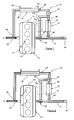
- the figure 1 illustrates an internal combustion engine 10, in particular of diesel type, and a recirculated exhaust gas circulation circuit 12 (or EGR circuit) with a filtration of these gases and advantageously a cooling of these same gases.
- the engine comprises at least one cylinder 14 with a combustion chamber 16 in which the combustion of a fuel mixture occurs.
- This engine also comprises an intake manifold 18 connecting all the inlet means (not shown) of the engine, such as pipes with intake valves, and connected to a fresh air intake pipe 20 supercharged or not supercharged.
- This engine also comprises an exhaust manifold 22 for collecting, through exhaust means also not shown (exhaust pipes and exhaust valves), the exhaust gas resulting from combustion in the combustion chambers to evacuate them through an exhaust line 24.
- the EGR circuit 12 comprises a recirculated exhaust gas flow pipe 26 (or EGR pipe) connecting the engine exhaust, here at a stitching point 28 on the exhaust line 24, with the engine intake, here with a connection point 30 with the fresh air intake pipe 20.
- this EGR pipe can alternatively connect the exhaust manifold with the intake manifold.
- This EGR pipe carries, in a direction from the stitching 28 to the connection point 30 of the intake pipe 20, a particulate filter 32, which, in the case of the example described, is a non-catalyzed filter, a valve means 34 (or EGR valve), and a recirculated exhaust gas cooler 36.
- the filter is advantageously a monolith with a honeycomb structure having a multiplicity of channels plugged alternately at their ends to force the gas Recirculated exhaust through the channel walls.
- the EGR valve 34 is here a two-way valve for controlling the circulation of the recirculated exhaust gas in the EGR pipe through a multiplicity of positions between a fully open position (indicated in solid lines) and a fully closed position ( illustrated with dashed lines).
- the cooler 36 comprises, by way of example, a casing 38 comprising tubes traversed internally by the recirculated exhaust gas and swept externally by a cooling fluid between an inlet 40 and an outlet 42 of this cooling fluid.
- a conduit 44 substantially parallel to the filter 32 and connecting a branch point 46 of the exhaust line 24 between the exhaust manifold 22 and the tapping 28 with an intersection 48 of the pipe 26 downstream of the filter and more particularly between the particulate filter 32 and the EGR valve (considering the direction of circulation of the recirculated gases during conventional operation).
- a valve means here a three-way valve 50, is placed at the branch point 46 and thus makes it possible to control the flow of the exhaust gases leaving the exhaust manifold 22 either towards the exhaust line 24 or to the conduit 44.
- the design of the duct 44, the filter 32 and the pipe 26 is such that it allows to circulate all the exhaust gas leaving the exhaust manifold 22 during the regeneration sequence of the filter.
- This engine also comprises an engine control unit (not shown), or engine control unit, which makes it possible to control the valves 34 and 50.
- This calculator also comprises maps or data tables allowing, for example, depending on the difference in pressure between the inlet and the outlet of the filter 32, the operating time of this filter or the temperature of the gases at the outlet of the filter, to trigger the regeneration of this particulate filter 32.
- the valve 50 is in the position indicated in strong lines so as to let the exhaust gases G leaving the exhaust manifold flow into the exhaust 24 while preventing the flow of these gases in the conduit 44 .
- the EGR valve 34 opens to a position between its fully closed position shown in dotted lines and its position of barely opening (in lines strong). Through this opening, a portion of the exhaust gas flowing in the line 24 is introduced through the stitching point 28 in the pipe 26 thus forming recirculated exhaust gas R.
- These recirculated exhaust gases pass through the filter. particles 32 by which the particles contained in these gases are captured and retained.
- the recirculated exhaust gases R are largely free of their particles and reach the EGR valve. These gases then pass through this valve and the cooler 36 through which they are cooled and finally reach the admission 20 to a desired temperature. These gases cooled and freed of their particles are mixed with the intake air (Arrow A) at the point of connection 30 to then be introduced into the combustion chambers 16 of the cylinders 14. Because of this, the EGR valve 34, the cooler 36, the major part of the pipe 26 and the intake of the engine are not fouled by the particles initially contained in the recirculated exhaust gas. In the case where the engine computer determines that the filter 32 is in saturation state, the regeneration sequence of this filter is then started.
- the EGR valve 34 is controlled so that it reaches the position shown in dashed lines where it prevents any flow to the cooler 36 and consequently any flow of recirculated gas to the inlet 20.
- the valve 50 is then controlled for obtain the position shown in dashed lines through which the exhaust gases leaving the manifold are deflected, here in their entirety, to the conduit 44.
- these gases arrive at the intersection 48 and cross, in the opposite direction of the initial course of recirculated gases R, the filter to ensure the regeneration thereof.
- the exhaust gases are then directed to the stitching point 28 where they are evacuated by the line 24.
- This regeneration is carried out via the exhaust gases which pass through the filter, ensuring the combustion of the particles contained in this filter, generally by an increase in the temperature of these exhaust gases.
- this increase in temperature can be achieved by any means, such as by increasing the richness of the fuel mixture in the combustion chambers of the cylinders, afterburning in these chambers, by an injection of fuel at the exhaust upstream of the filter, ...
- the very hot exhaust gases (of the order of 700 ° C. to 900 ° C.) leaving the filter, and whose high temperature level results from the combustion of the particles are not sent to the cooler 36 which is not designed to withstand such a temperature.
- the ashes resulting from the combustion of the particles are not directed to the intake, where they would have caused disturbances during combustion, but to the exhaust 24.
- the counter-flow circulation of the exhaust gas has the advantage of facilitating filter de-clogging.
- this regeneration sequence is started when the engine does not require the introduction of recirculated exhaust gas at the intake, in particular for the high and full loads of the engine.
- FIG 2 illustrates a variant of the engine of the figure 1 .
- This variant differs from the example of figure 1 in that the EGR valve is replaced by a three-way valve 52 which is placed at the intersection 48 between the conduit 44 and the pipe 26.
- This valve thus allows, in addition to being able to control the circulation of the recirculated gases in the conduct 26 EGR circuit 12, direct the exhaust gas flowing in the conduit 44 to the cooler 36, or to the filter 32, or to both at once.
- the valve 50 is in the position illustrated in solid lines on the figure 2 and the valve 52 may be in a position between that of full closure of the pipe 26 (indicated by centerlines) and that of full opening as shown in bold line.
- the circulation of exhaust gases and / or recirculated exhaust gas is identical to that already described in connection with the figure 1 with arrows in solid lines.
- the exhaust gases G leaving the exhaust manifold 22 circulate in the exhaust 24 with the possibility of circulating a portion of these exhaust gases in the pipe 26, depending on the position of the valve 52, thus forming recirculated exhaust gases R.
- the computer estimates that the filter 32 is saturated and must be regenerated, it controls the valve 50 so that it is in the position illustrated by dashed lines at the figure 2 with the deviation of the exhaust gases leaving the manifold, here in total, towards the duct 44.
- the valve 52 is then controlled in a multiplicity of positions with a position to prevent, as previously described in connection with the figure 1 , any flow of gas to the cooler 36. Therefore, the exhaust gas arriving at the intersection 48 through the filter, in the opposite direction of the initial course of the recirculated gas R, to ensure regeneration thereof.
- the exhaust gases are then directed to the stitching point 28 where they are discharged through line 24.
- the exhaust gas arriving at the intersection 48 are split into two reverse flow direction exhaust streams as shown by dashed arrows.
- valve 52 it is possible, thanks to the valve 52, to bypass this filter to supply the intake of the engine with recirculated exhaust gas.
- the position of the valve 50 is that shown in dashed lines on the figure 2 with the deflection of the exhaust gas exiting the manifold to the duct 44.
- the valve 52 is controlled to arrive in a position such that it prevents any flow of gas from the duct 44 to the filter 32 but authorizes the circulation of these exhaust gases from the intersection 48 to the inlet 20.
- the present invention is not limited to the example described above but encompasses all variants and all equivalents.
- the exhaust gas cooler can be a heat exchanger of all types and in particular the one better known in the form of spaced apart plates stacked one on the other. This makes it possible to obtain channels with circulation of a coolant and channels with recirculated exhaust gas circulation.
- the EGR valve may be placed either downstream or upstream of the cooler 36, but preferably this valve is placed downstream of the latter, as illustrated in the figures.
- the exhaust line 24 may carry a main particle filter in addition to the particle filter of the EGR circuit. This main filter can be placed downstream of the stitching point 28 to ensure the filtration of the exhaust gas flowing in this line before their release into the atmosphere. In this case, it can be envisaged to ensure the regeneration of the two filters simultaneously when the computer determines that at least one of these filters is saturated.
- an additional particulate filter 54 preferably catalyzed, as indicated in center line on the Figures 1 and 2 and that for configurations described above according to which all or part of the exhaust gas flows from the intersection 48 to the inlet 20 without having first passed through the filter 32.
- This has the main advantage of being able to send, through of the valve 34 or 52 and the cooler 36, recirculated exhaust gases freed of a large part of their particles by passing through the additional filter while ensuring the regeneration of the filter 32.
- oxidation catalyst with the particulate filter or to use a catalyzed filter in place of the filter 32 in order to make it possible to eliminate moreover sources of fouling, such as, for example unburned hydrocarbons (HC)
Landscapes
- Engineering & Computer Science (AREA)
- Chemical & Material Sciences (AREA)
- Combustion & Propulsion (AREA)
- Mechanical Engineering (AREA)
- General Engineering & Computer Science (AREA)
- Chemical Kinetics & Catalysis (AREA)
- Processes For Solid Components From Exhaust (AREA)
- Exhaust-Gas Circulating Devices (AREA)
Abstract
Description
- La présente invention se rapporte à un procédé pour la filtration des gaz d'échappement recirculés d'un moteur à combustion interne, plus particulièrement de type Diesel, et un moteur pour utiliser un tel procédé.
- Elle concerne notamment un moteur avec un circuit de circulation des gaz d'échappement recirculés ou circuit EGR (Exhaust Gas Recirculation) qui sont prélevés à partir de l'échappement du moteur, comme le collecteur ou la ligne d'échappement, pour les faire parvenir à l'admission de ce même moteur.
- Ces gaz d'échappement recirculés sont habituellement utilisés pour diminuer la quantité de polluants émis par le moteur en permettant de minimiser les émissions d'oxydes d'azote (NOx) par abaissement de la température de combustion.
- Ces gaz d'échappement peuvent cependant être à une température très élevée (de l'ordre de 500°C) suivant les points de fonctionnement du moteur et il peut être nécessaire de les refroidir avant leur introduction à l'admission du moteur.
- Dans ce cas, ce refroidissement s'effectue par passage au travers d'un échangeur de chaleur, plus connu sous la dénomination de refroidisseur de gaz d'échappement recirculés (EGRC pour Exhaust Gas Recirculation Cooler), qui est parcouru par un fluide de refroidissement et qui absorbe les calories contenues dans les gaz.
De manière usuelle mais non exclusive, ce fluide provient d'une dérivation du circuit de refroidissement du moteur qui comporte habituellement un radiateur de refroidissement et une pompe de circulation du fluide. - Dans ce circuit EGR, il est également prévu une vanne, dite vanne EGR, qui est placée soit en amont, soit en aval de ce refroidisseur et qui est utilisée pour contrôler la quantité de gaz d'échappement circulant dans le circuit de circulation.
- Sous l'impulsion de normes de plus en plus sévères nécessitant une augmentation du taux de gaz d'échappement recirculés et du refroidissement de ceux-ci, le problème posé par une telle installation réside dans le fait que non seulement la vanne EGR mais aussi le refroidisseur de gaz d'échappement recirculés (s'il est présent dans le circuit) subissent un encrassement par les particules contenues dans ces gaz d'échappement, ces particules étant généralement un résidu de la combustion dans les cylindres du moteur.
De plus, cet encrassement touche également toutes les parties du circuit d'admission d'air en contact avec les gaz d'échappement recirculés comme le collecteur d'admission, les tubulures d'admission, les soupapes d'admission, les capteurs placés dans le collecteur d'admission, ... - Un tel encrassement est souvent à l'origine de nombreux disfonctionnements pouvant entraîner une perte d'efficacité d'un ou plusieurs des éléments constitutifs du circuit EGR.
Ainsi, il peut se produire une situation dans laquelle l'encrassement de la vanne est telle qu'elle ne permette plus de contrôler la quantité de gaz d'échappement circulant dans le circuit EGR.
En effet, la vanne est soumise à des variations de températures qui conduisent à une modification structurelle du dépôt de particules qui le rend très adhérent sur les différentes surfaces de cette vanne. Ceci altère la capacité d'étanchéité entre les différents éléments de cette vanne, comme le clapet et son siège de clapet, ou empêche le mouvement de ce clapet.
De plus, certaines parties du refroidisseur, comme par exemple les tubes de refroidissement qui sont traversés par les gaz d'échappement recirculés, sont recouvertes d'une couche de particules, au bout d'un certain temps d'utilisation. Cette couche fait obstacle au transfert de chaleur entre ces gaz et le fluide de refroidissement en diminuant ainsi la performance de ce refroidisseur et sa perméabilité due à l'obstruction, par des particules, des entrées de tubes. - Dans des cas extrêmes, pour obtenir un fonctionnement adéquat du circuit EGR, il est nécessaire de procéder, périodiquement, au démontage de la vanne et/ou du refroidisseur pour les nettoyer.
Cela a pour inconvénient de rendre inopérationnel le moteur et d'immobiliser le véhicule durant le temps nécessaire aux opérations de démontage, nettoyage et remontage. - Pour minimiser l'encrassement de tout ou partie des constituants du circuit EGR, il est connu, par le document
US 5 440 880 , de placer un filtre à particules catalysé autorégénérable dans le circuit de circulation de gaz d'échappement recirculés. Ce filtre a pour particularité de contenir des éléments catalytiques permettant, lors de réactions chimiques, d'éliminer, de manière continuelle, les particules qu'il a captées et ce pendant toute la durée de fonctionnement du circuit EGR. - Cette disposition de filtre, bien que donnant satisfaction, présente l'inconvénient non négligeable d'être d'un coût élevé car les éléments catalytiques sont principalement à base de métaux précieux, comme le platine.
De plus, ce filtre ne peut pas être utilisé en permanence car il ne peut être opérationnel que lorsque la température des gaz d'échappement recirculés qui le traversent est suffisante pour activer les éléments catalytiques.
En outre, ce filtre catalysé autorégénérable perd de son efficacité au fil du temps de par la dégradation habituelle des éléments catalytiques et nécessite à terme son remplacement par un nouveau filtre. De même, cela nécessite l'immobilisation du véhicule pour réaliser les opérations de démontage/remontage d'un nouveau filtre. - La présente invention se propose de remédier aux inconvénients ci-dessus mentionnés grâce à une installation dans laquelle le filtre à particules peut être régénéré et utilisé quelques soient les conditions de fonctionnement du moteur.
- A cet effet, la présente invention concerne un procédé pour la filtration de gaz d'échappement recirculés d'un moteur à combustion interne, notamment de type Diesel, comportant un circuit de circulation pour des gaz d'échappement recirculés allant de l'échappement de ce moteur vers son admission, ledit circuit comprenant une conduite de circulation avec des moyens de vannage pour contrôler la circulation des gaz recirculés dans le circuit et un filtre à particules en amont desdits moyens de vannage pour capter les particules contenues dans les gaz recirculés lorsque ceux-ci traversent ledit filtre dans un sens de circulation conventionnel allant de l'échappement vers l'admission, caractérisé en ce que le procédé consiste, pour la régénération du filtre à particules, à faire traverser ledit filtre par au moins une partie des gaz d'échappement dans un sens de circulation inverse au sens conventionnel.
- Ce procédé peut consister, pour la régénération du filtre à particules, à positionner les moyens de vannage dans une position de fermeture pour empêcher la circulation des gaz entre lesdits moyens de vannage et ladite admission et à diriger les gaz d'échappement de l'échappement vers une intersection du circuit située en aval dudit filtre pour qu'ils traversent le filtre.
- Ce procédé peut consister, pour la régénération du filtre à particules, à diriger les gaz d'échappement de l'échappement vers une intersection du circuit située en aval dudit filtre et à commander les moyens de vannage pour qu'au moins une partie de ces gaz traverse le filtre dans un sens allant de l'intersection à l'échappement.
- Ce procédé peut consister, pour la régénération du filtre à particules, à commander lesdits moyens de vannage pour qu'une partie des gaz d'échappement traverse le filtre dans un sens allant de l'intersection à l'échappement et pour qu'une autre partie de ces gaz circulent de cette intersection vers l'admission.
- Ce procédé peut consister à régénérer le filtre à particules lorsque le fonctionnement du moteur ne nécessite pas l'introduction de gaz d'échappement recirculés à son admission.
- L'invention concerne également un moteur à combustion interne, notamment de type Diesel, avec un circuit de circulation de gaz d'échappement recirculés allant de l'échappement de ce moteur à son admission, ledit circuit comprenant une conduite de circulation, des moyens de vannage pour contrôler la circulation des gaz recirculés dans le circuit et un filtre à particules en amont desdits moyens de vannage pour capter les particules contenues dans les gaz recirculés lorsque ceux-ci traversent ledit filtre dans un sens de circulation conventionnel allant de l'échappement vers l'admission, caractérisé en ce que le moteur comprend des moyens de vannage sur l'échappement permettant, pour la régénération du filtre, de faire traverser ledit filtre par au moins une partie des gaz d'échappement dans un sens de circulation inverse au sens de circulation conventionnel.
- Le moteur peut comprendre un conduit raccordant l'échappement à une intersection du circuit située en aval dudit filtre.
- Avantageusement, ie moteur peut comprendre un filtre additionnel disposé sur le conduit.
- Le moteur peut comprendre des moyens de vannage placés à l'intersection.
- Le moteur peut comprendre un refroidisseur de gaz d'échappement recirculés placé sur le circuit de circulation de gaz d'échappement recirculés.
- Les autres caractéristiques et avantages de l'invention seront mieux décrits à la lecture de la description qui va suivre, donnée à titre uniquement illustratif et non limitatif, et en se référant aux dessins annexés sur lesquels :
- la
figure 1 est un schéma d'un moteur avec le circuit de circulation des gaz d'échappement en fonctionnement conventionnel et avec régénération du filtre à particules et - la
figure 2 est une variante du schéma du moteur de lafigure 1 avec un fonctionnement conventionnel et avec la régénération du filtre à particules. - La
figure 1 illustre un moteur à combustion interne 10, notamment de type Diesel, ainsi qu'un circuit de circulation de gaz d'échappement recirculés 12 (ou circuit EGR) avec une filtration de ces gaz et avantageusement un refroidissement de ces mêmes gaz.
Le moteur comprend au moins un cylindre 14 avec une chambre de combustion 16 dans laquelle se produit la combustion d'un mélange carburé. Ce moteur comprend également un collecteur d'admission 18 reliant tous les moyens d'admission (non représentés) du moteur, comme des tubulures avec des soupapes d'admission, et raccordé à une conduite d'admission d'air frais 20 suralimenté ou non suralimenté. Ce moteur comprend aussi un collecteur d'échappement 22 permettant de collecter, au travers de moyens d'échappement également non représentés (tubulures d'échappement et soupapes d'échappement), les gaz d'échappement résultant de la combustion dans les chambres de combustion pour les évacuer par une ligne d'échappement 24.
Le circuit EGR 12 comprend une conduite de circulation de gaz d'échappement recirculés 26 (ou conduite EGR) reliant l'échappement du moteur, ici en un point de piquage 28 sur la ligne d'échappement 24, avec l'admission du moteur, ici avec un point de liaison 30 avec la conduite d'admission d'air frais 20. - Bien entendu et cela sans sortir du cadre de l'invention, cette conduite EGR peut alternativement relier le collecteur d'échappement avec le collecteur d'admission.
Cette conduite EGR porte, dans un sens allant du piquage 28 vers le point de liaison 30 de la conduite d'admission 20, un filtre à particules 32, qui, dans le cas de l'exemple décrit, est un filtre non catalysé, un moyen de vannage 34 (ou vanne EGR), et un refroidisseur de gaz d'échappement recirculés 36. Le filtre est avantageusement un monolithe avec une structure en nid d'abeille comportant une multiplicité de canaux bouchés alternativement à leurs extrémités pour obliger les gaz d'échappement recirculés à traverser les cloisons des canaux. La vanne EGR 34 est ici une vanne deux voies permettant de contrôler la circulation des gaz d'échappement recirculés dans la conduite EGR grâce à une multiplicité de positions entre une position de pleine ouverture (indiquée en trait plein) et une position de pleine fermeture (illustrée par des traits pointillés). Le refroidisseur 36 comprend, à titre d'exemple, un carter 38 comportant des tubes parcourus intérieurement par les gaz d'échappement recirculés et balayés extérieurement par un fluide de refroidissement entre une admission 40 et une sortie 42 de ce fluide de refroidissement.
De plus, il est prévu un conduit 44 sensiblement parallèle au filtre 32 et reliant un point d'embranchement 46 de la ligne d'échappement 24 entre le collecteur d'échappement 22 et le piquage 28 avec une intersection 48 de la conduite 26 en aval du filtre et plus particulièrement entre le filtre à particules 32 et la vanne EGR (en considérant le sens de circulation des gaz recirculés lors du fonctionnement conventionnel). Un moyen de vannage, ici une vanne 50 à trois voies, est placée au point d'embranchement 46 et permet ainsi de contrôler la circulation des gaz d'échappement sortant du collecteur d'échappement 22 soit vers la ligne d'échappement 24, soit vers le conduit 44.
Bien entendu, le dimensionnement du conduit 44, du filtre 32 et de la conduite 26 est telle qu'il permette de laisser circuler la totalité des gaz d'échappement sortant du collecteur d'échappement 22 lors de la séquence de régénération du filtre. - Ce moteur comprend également une unité de contrôle du moteur (non représenté), ou calculateur moteur, qui permet de contrôler les vannes 34 et 50. Ce calculateur comprend également des cartographies ou des tables de données permettant, par exemple en fonction de la différence de pression entre l'entrée et la sortie du filtre 32, du temps de fonctionnement de ce filtre ou de la température des gaz en sortie du filtre, de déclencher la régénération de ce filtre à particules 32.
- Le fonctionnement du moteur va être maintenant décrit en relation avec les différents cheminements des gaz, comme illustrés sur la figure, avec des flèches pleines pour la circulation des gaz en fonctionnement conventionnel du moteur et avec des flèches pointillées pour la séquence de régénération du filtre.
- Pour le fonctionnement conventionnel, la vanne 50 est dans la position indiquée en trait fort de manière à laisser circuler les gaz d'échappement G sortant du collecteur d'échappement dans l'échappement 24 tout en interdisant la circulation de ces gaz dans le conduit 44.
En cas de besoin d'introduction de gaz d'échappement recirculés à l'admission du moteur, la vanne EGR 34 s'ouvre pour une position comprise entre sa position de pleine fermeture illustrée en trait pointillé et sa position de peine ouverture (en trait fort). De par cette ouverture, une partie des gaz d'échappement circulant dans la ligne 24 est introduite par le point de piquage 28 dans la conduite 26 en formant ainsi des gaz d'échappement recirculés R. Ces gaz d'échappement recirculés traversent le filtre à particules 32 grâce auquel les particules contenues dans ces gaz sont captées et retenues. En sortie du filtre à particules, les gaz d'échappement recirculés R sont débarrassés, en très grande partie, de leurs particules et parviennent à la vanne EGR. Ces gaz traversent ensuite cette vanne puis le refroidisseur 36 grâce auquel ils sont refroidis et parviennent enfin à l'admission 20 à une température souhaitée. Ces gaz refroidis et débarrassés de leurs particules sont mélangés avec l'air d'admission (Flèche A) au point de liaison 30 pour être ensuite introduits dans les chambres de combustion 16 des cylindres 14.
Grâce à cela la vanne EGR 34, le refroidisseur 36, la majeure partie de la conduite 26 et l'admission du moteur ne sont pas encrassés par les particules initialement contenues dans les gaz d'échappement recirculés.
Dans le cas où le calculateur moteur détermine que le filtre 32 est en état de saturation, la séquence de régénération de ce filtre est alors lancée.
Pour cela, la vanne EGR 34 est commandée pour qu'elle atteigne la position illustrée en traits pointillés où elle empêche toute circulation vers le refroidisseur 36 et par conséquent toute circulation de gaz recirculés vers l'admission 20. La vanne 50 est alors commandée pour obtenir la position illustrée en traits pointillés grâce à laquelle les gaz d'échappement sortant du collecteur sont déviés, ici dans leur totalité, vers le conduit 44. Comme la vanne EGR 34 est en position de fermeture, ces gaz arrivent à l'intersection 48 et traversent, dans le sens inverse du parcours initial des gaz recirculés R, le filtre pour assurer la régénération de celui-ci. Les gaz d'échappement sont ensuite dirigés vers le point de piquage 28 d'où ils sont ils sont évacués par la ligne 24.
Cette régénération est réalisée par l'intermédiaire des gaz d'échappement qui traversent le filtre en assurant la combustion des particules contenues dans ce filtre, généralement par une augmentation de la température de ces gaz d'échappement. Comme cela est largement connu par l'homme du métier, cette augmentation de température peut être réalisée par tout moyen, comme par une augmentation de la richesse du mélange carburé dans les chambres de combustion des cylindres, une post-combustion dans ces chambres, par une injection de carburant à l'échappement en amont du filtre,...
Ainsi, les gaz d'échappement très chauds (de l'ordre de 700°C à 900°C) sortant du filtre, et dont le haut niveau de température résulte de la combustion des particules, ne sont pas envoyés au refroidisseur 36 qui n'est pas prévu pour supporter une telle température. En outre, les cendres résultant de la combustion des particules ne sont pas dirigées à l'admission, où elles auraient entraînées des perturbations lors de la combustion, mais vers l'échappement 24. - De plus, la circulation à contre sens des gaz d'échappement a pour avantage de faciliter le désencrassement du filtre
- Avantageusement mais non obligatoirement, cette séquence de régénération est lancée lorsque le moteur ne nécessite pas l'introduction de gaz d'échappement recirculés à l'admission, notamment pour les fortes et pleines charges du moteur.
- On se reporte maintenant à la
figure 2 qui illustre une variante du moteur de lafigure 1 .
Cette variante se distingue de l'exemple de lafigure 1 par le fait que la vanne EGR est remplacée par une vanne trois voies 52 qui est placée à l'intersection 48 entre le conduit 44 et la conduite 26. Cette vanne permet ainsi, outre le fait de pouvoir contrôler la circulation des gaz recirculés dans la conduite 26 du circuit EGR 12, de diriger les gaz d'échappement circulant dans le conduit 44 soit vers le refroidisseur 36, soit vers le filtre 32, soit vers les deux à la fois. - Ainsi en fonctionnement conventionnel du moteur, la vanne 50 est dans la position illustrée en trait fort sur la
figure 2 et la vanne 52 peut être dans une position comprise entre celle de pleine fermeture de la conduite 26 (indiquée par des traits d'axe) et celle de pleine ouverture comme illustré en trait fort.
Dans cette configuration, la circulation des gaz d'échappement et/ou des gaz d'échappement recirculés est identique à celle déjà décrite en relation avec lafigure 1 avec des flèches en traits pleins.
Ainsi, les gaz d'échappement G sortant du collecteur d'échappement 22 circulent dans l'échappement 24 avec la possibilité de faire circuler une partie de ces gaz d'échappement dans la conduite 26, en fonction de la position de la vanne 52, en formant ainsi des gaz d'échappement recirculés R. Ces gaz d'échappement recirculés traversent le filtre à particules 32, la vanne 52, le refroidisseur 36 et aboutissent à l'admission 20 où ils sont mélangés avec l'air d'admission (Flèche A) au point de liaison 30 pour être ensuite introduits dans les chambres de combustion 16 des cylindres 14. - Lorsque le calculateur estime que le filtre 32 est saturé et doit être régénéré, il commande la vanne 50 pour qu'elle soit dans la position illustrée par des traits pointillés à la
figure 2 avec la déviation des gaz d'échappement sortant du collecteur, ici en totalité, vers le conduit 44.
La vanne 52 est ensuite commandée dans une multiplicité de positions avec une position permettant d'empêcher, comme précédemment décrit en relation avec lafigure 1 , toute circulation de gaz vers le refroidisseur 36. De ce fait, les gaz d'échappement arrivant à l'intersection 48 traversent le filtre, dans le sens inverse du parcours initial des gaz recirculés R, pour assurer la régénération de celui-ci. Les gaz d'échappement sont ensuite dirigés vers le point de piquage 28 d'où ils sont évacués par la ligne 24. Dans une autre position de la vanne 52, illustrée en traits pointillés sur la figure, les gaz d'échappement arrivant à l'intersection 48 sont partagés en deux courants de gaz d'échappement de sens de circulation inverse, comme montré par des flèches en traits pointillés. L'un de ces courants traverse le filtre, dans le sens inverse du parcours initial des gaz recirculés R, pour assurer la régénération de celui-ci alors que l'autre de ces courants traverse le refroidisseur 36 grâce auquel ils sont refroidis pour parvenir à l'admission 20.
Grâce à cette disposition, il est possible d'assurer la régénération du filtre à particules avec une sortie de gaz très chauds et contenant des cendres vers la ligne 24 tout en permettant la circulation de gaz recircuiés, à une température compatible avec le refroidisseur 36, vers l'admission 20 du moteur. - En outre, il est possible, grâce à la vanne 52, de court-circuiter ce filtre pour alimenter l'admission du moteur en gaz d'échappement recirculés. Pour cela, la position de la vanne 50 est celle montrée en traits pointillés sur la
figure 2 avec la déviation des gaz d'échappement sortant du collecteur vers le conduit 44. La vanne 52 est commandée pour arriver dans une position telle qu'elle empêche toute circulation de gaz provenant du conduit 44 vers le filtre 32 mais autorise la circulation de ces gaz d'échappement de l'intersection 48 vers l'admission 20.
La présente invention n'est pas limitée à l'exemple décrit ci-dessus mais englobe toutes variantes et tout équivalents. - Notamment, le refroidisseur de gaz d'échappement peut être un échangeur de chaleur de tous types et en particulier celui plus connu sous la forme de plaques espacées empilées les unes sur les autres. Cela permet d'obtenir des canaux avec une circulation d'un fluide caloporteur et des canaux avec une circulation de gaz d'échappement recirculés.
- La vanne EGR peut être placée soit en aval, soit en amont du refroidisseur 36, mais préférentiellement cette vanne est placée en aval de ce dernier, comme illustré sur les figures.
La ligne d'échappement 24 peut porter un filtre à particules principal en plus du filtre à particules du circuit EGR. Ce filtre principal peut être placé en aval du point de piquage 28 pour assurer la filtration des gaz d'échappement circulant dans cette ligne avant leur rejet dans l'atmosphère.
Dans ce cas, il peut être envisagé d'assurer la régénération des deux filtres simultanément lorsque le calculateur déterminera que l'un au moins de ces filtres est saturé. - De plus, il peut être envisagé de placer, sur le conduit 44, un filtre à particules additionnel 54, de préférence catalysé, comme indiqué en trait d'axe sur les
figures 1 et 2 et cela pour des configurations décrites ci-dessus selon lesquelles tout ou partie des gaz d'échappement circule de l'intersection 48 vers l'admission 20 sans avoir au préalable traversé le filtre 32. Cela a pour avantage principal de pouvoir envoyer, au travers de la vanne 34 ou 52 et du refroidisseur 36, des gaz d'échappement recirculés débarrassés d'une grande partie de leur particules par passage au travers du filtre additionnel tout en assurant la régénération du filtre 32. - En outre, il peut être également envisagé d'associer un catalyseur d'oxydation au filtre à particules ou d'utiliser un filtre catalysé lieu et place du filtre 32 pour permettre d'éliminer d'avantage de sources d'encrassement, comme par exemple les hydrocarbures imbrûlés (HC)
Claims (10)
- Procédé pour la filtration de gaz d'échappement recirculés d'un moteur à combustion interne, notamment de type Diesel, comportant un circuit de circulation pour des gaz d'échappement recirculés (12) allant de l'échappement (22, 24) de ce moteur vers son admission (18, 20), ledit circuit comprenant une conduite de circulation (26) avec des moyens de vannage (34, 52) pour contrôler la circulation des gaz recirculés dans le circuit et un filtre (32) en amont desdits moyens de vannage pour capter les particules contenues dans les gaz recirculés lorsque ceux-ci traversent ledit filtre dans un sens de circulation conventionnel allant de l'échappement (22, 24) vers l'admission (18, 20), caractérisé en ce que le procédé consiste, pour la régénération du filtre à particules (32), à faire traverser ledit filtre par au moins une partie des gaz d'échappement dans un sens de circulation inverse au sens conventionnel.
- Procédé pour la filtration de gaz d'échappement recirculés d'un moteur à combustion interne selon la revendication 1, caractérisé en ce qu'il consiste, pour la régénération du filtre à particules, à positionner les moyens de vannage (34) dans une position de fermeture pour empêcher la circulation des gaz entre lesdits moyens de vannage et ladite admission et à diriger les gaz d'échappement de l'échappement (22, 24) vers une intersection (48) du circuit (12) située en aval dudit filtre pour qu'ils traversent le filtre (32).
- Procédé pour ia filtration de gaz d'échappement recirculés d'un moteur à combustion interne selon la revendication 1, caractérisé en ce qu'il consiste, pour la régénération du filtre à particules, à diriger les gaz d'échappement de l'échappement (22, 24) vers une intersection (48) du circuit (12) située en aval dudit filtre et à commander les moyens de vannage (52) pour qu'au moins une partie de ces gaz traverse le filtre (32) dans un sens allant de l'intersection (48) à l'échappement (22, 24).
- Procédé pour la filtration de gaz d'échappement recirculés d'un moteur à combustion interne selon la revendication 3, caractérisé en ce qu'il consiste, pour la régénération du filtre à particules, à commander lesdits moyens de vannage (52) pour qu'une partie des gaz d'échappement traverse le filtre dans un sens allant de l'intersection (48) à l'échappement (22, 24) et pour qu'une autre partie de ces gaz circulent de cette intersection (48) vers l'admission (18, 20).
- Procédé pour la filtration de gaz d'échappement recirculés d'un moteur à combustion interne selon l'une des revendications précédentes, caractérisé en ce qu'il consiste à régénérer le filtre à particules lorsque le fonctionnement du moteur ne nécessite pas l'introduction de gaz d'échappement recirculés à son admission (18, 20).
- Moteur à combustion interne, notamment de type Diesel, avec un circuit de circulation de gaz d'échappement recirculés (12) allant de l'échappement (22, 24) de ce moteur à son admission (18, 20), ledit circuit comprenant une conduite de circulation (26), des moyens de vannage (34, 52) pour contrôler la circulation des gaz recirculés dans le circuit et un filtre (32) en amont desdits moyens de vannage pour capter les particules contenues dans les gaz recirculés lorsque ceux-ci traversent ledit filtre dans un sens de circulation conventionnel allant de l'échappement (22, 24) vers l'admission (18, 20), caractérisé en ce que le moteur comprend des moyens de vannage (50) sur l'échappement (24) permettant, pour la régénération du filtre, de faire traverser ledit filtre par au moins une partie des gaz d'échappement dans un sens de circulation inverse au sens de circulation conventionnel.
- Moteur à combustion interne avec un circuit de circulation de gaz d'échappement recirculés selon la revendication 6, caractérisé en ce qu'il comprend un conduit (44) raccordant l'échappement (22, 24) à une intersection (48) du circuit (12) située en aval dudit filtre.
- Moteur à combustion interne avec un circuit de circulation de gaz d'échappement recirculés selon la revendication 7, caractérisé en ce qu'il comprend un filtre additionnel (54) disposé sur conduit (44).
- Moteur à combustion interne avec un circuit de circulation de gaz d'échappement recirculés selon l'une des revendications 6 à 8, caractérisé en ce qu'il comprend des moyens de vannage (52) placés à l'intersection (48).
- Moteur à combustion interne avec un circuit de circulation de gaz d'échappement recirculés selon l'une des revendications 6 à 9, caractérisé en ce qu'il comprend un refroidisseur de gaz d'échappement recirculés (36) placé sur le circuit de circulation de gaz d'échappement recirculés (12).
Applications Claiming Priority (1)
| Application Number | Priority Date | Filing Date | Title |
|---|---|---|---|
| FR0705169A FR2919027B1 (fr) | 2007-07-17 | 2007-07-17 | Procede pour la filtration des gaz d'echappement recircules d'un moteur a combustion interne et moteur pour utiliser un tel procede |
Publications (1)
| Publication Number | Publication Date |
|---|---|
| EP2025914A1 true EP2025914A1 (fr) | 2009-02-18 |
Family
ID=39111783
Family Applications (1)
| Application Number | Title | Priority Date | Filing Date |
|---|---|---|---|
| EP08290634A Withdrawn EP2025914A1 (fr) | 2007-07-17 | 2008-06-27 | Procédé pour la filtration des gaz d'échappement recirculés d'un moteur à combustion interne et moteur utilisant un tel procédé. |
Country Status (2)
| Country | Link |
|---|---|
| EP (1) | EP2025914A1 (fr) |
| FR (1) | FR2919027B1 (fr) |
Cited By (4)
| Publication number | Priority date | Publication date | Assignee | Title |
|---|---|---|---|---|
| FR2949818A1 (fr) * | 2009-09-10 | 2011-03-11 | Peugeot Citroen Automobiles Sa | Dispositif de traitement de gaz d'echappement, ligne d'echappement et procede de controle |
| WO2012041455A1 (fr) * | 2010-10-01 | 2012-04-05 | Haldor Topsøe /S | Procédé et système se rapportant au retrait de matière sous forme de particules se trouvant dans les gaz d'échappement de moteur |
| DE102012017278A1 (de) * | 2012-08-31 | 2014-03-06 | Volkswagen Aktiengesellschaft | Antriebsaggregat für ein Kraftfahrzeug und Verfahren zurn Betreiben eines solchen |
| GB2614096A (en) * | 2021-05-28 | 2023-06-28 | Jaguar Land Rover Ltd | Exhaust system, controller and method for an internal combustion engine |
Families Citing this family (1)
| Publication number | Priority date | Publication date | Assignee | Title |
|---|---|---|---|---|
| CN104279089A (zh) * | 2013-05-28 | 2015-01-14 | 福特汽车萨纳伊股份有限公司 | 排气再循环系统 |
Citations (5)
| Publication number | Priority date | Publication date | Assignee | Title |
|---|---|---|---|---|
| JPS59165816A (ja) | 1983-03-09 | 1984-09-19 | Mitsubishi Motors Corp | デイ−ゼルパテイキユレ−トフイルタの再生装置 |
| US5440880A (en) | 1994-05-16 | 1995-08-15 | Navistar International Transportation Corp. | Diesel engine EGR system with exhaust gas conditioning |
| JPH07259654A (ja) | 1994-03-22 | 1995-10-09 | Nissan Diesel Motor Co Ltd | ディーゼルエンジンの排気還流装置 |
| US5592925A (en) * | 1994-09-14 | 1997-01-14 | Ngk Insulators, Ltd. | Exhaust gas recirculation device for internal combustion engine |
| US20010027647A1 (en) * | 2000-03-28 | 2001-10-11 | Toyota Jidosha Kabushiki Kaisha | Device for purifying the exhaust gas of an internal combustion engine |
-
2007
- 2007-07-17 FR FR0705169A patent/FR2919027B1/fr not_active Expired - Fee Related
-
2008
- 2008-06-27 EP EP08290634A patent/EP2025914A1/fr not_active Withdrawn
Patent Citations (5)
| Publication number | Priority date | Publication date | Assignee | Title |
|---|---|---|---|---|
| JPS59165816A (ja) | 1983-03-09 | 1984-09-19 | Mitsubishi Motors Corp | デイ−ゼルパテイキユレ−トフイルタの再生装置 |
| JPH07259654A (ja) | 1994-03-22 | 1995-10-09 | Nissan Diesel Motor Co Ltd | ディーゼルエンジンの排気還流装置 |
| US5440880A (en) | 1994-05-16 | 1995-08-15 | Navistar International Transportation Corp. | Diesel engine EGR system with exhaust gas conditioning |
| US5592925A (en) * | 1994-09-14 | 1997-01-14 | Ngk Insulators, Ltd. | Exhaust gas recirculation device for internal combustion engine |
| US20010027647A1 (en) * | 2000-03-28 | 2001-10-11 | Toyota Jidosha Kabushiki Kaisha | Device for purifying the exhaust gas of an internal combustion engine |
Cited By (5)
| Publication number | Priority date | Publication date | Assignee | Title |
|---|---|---|---|---|
| FR2949818A1 (fr) * | 2009-09-10 | 2011-03-11 | Peugeot Citroen Automobiles Sa | Dispositif de traitement de gaz d'echappement, ligne d'echappement et procede de controle |
| WO2012041455A1 (fr) * | 2010-10-01 | 2012-04-05 | Haldor Topsøe /S | Procédé et système se rapportant au retrait de matière sous forme de particules se trouvant dans les gaz d'échappement de moteur |
| DE102012017278A1 (de) * | 2012-08-31 | 2014-03-06 | Volkswagen Aktiengesellschaft | Antriebsaggregat für ein Kraftfahrzeug und Verfahren zurn Betreiben eines solchen |
| GB2614096A (en) * | 2021-05-28 | 2023-06-28 | Jaguar Land Rover Ltd | Exhaust system, controller and method for an internal combustion engine |
| GB2614096B (en) * | 2021-05-28 | 2024-08-21 | Jaguar Land Rover Ltd | Exhaust system, controller and method for an internal combustion engine |
Also Published As
| Publication number | Publication date |
|---|---|
| FR2919027A1 (fr) | 2009-01-23 |
| FR2919027B1 (fr) | 2013-05-17 |
Similar Documents
| Publication | Publication Date | Title |
|---|---|---|
| JP5458009B2 (ja) | 排気後処理システム | |
| US8887702B2 (en) | Self-cleaning exhaust gas recirculation system | |
| JP5763294B2 (ja) | 排気浄化装置 | |
| CN107035471B (zh) | 用于内燃机的废气后处理的方法和装置 | |
| FR2919027A1 (fr) | Procede pour la filtration des gaz d'echappement recircules d'un moteur a combustion interne et moteur pour utiliser un tel procede | |
| EP2241742A1 (fr) | Système de suralimentation à double étage avec dispositif d'épuration de gaz d'échappement pour moteur à combustion interne et procédé pour commander un tel système | |
| CN101313132A (zh) | 废气净化系统的再生控制方法以及废气净化系统 | |
| FR2885178A1 (fr) | Groupe motopropulseur comportant un circuit de nettoyage d'un circuit de recirculation des gaz d'echappement | |
| FR2819549A1 (fr) | Systeme de traitement des gaz d'echappement d'un moteur a combustion | |
| WO2012041455A1 (fr) | Procédé et système se rapportant au retrait de matière sous forme de particules se trouvant dans les gaz d'échappement de moteur | |
| JPH0598932A (ja) | 内燃機関の排気浄化装置 | |
| FR2914701A1 (fr) | Installation pour le refroidissement des gaz d'echappement recircules de moteur a combustion interne et de la vanne de controle de la circulation de ces gaz. | |
| JP6805948B2 (ja) | 排気浄化装置 | |
| JP4737463B2 (ja) | 排気浄化装置 | |
| US20140360159A1 (en) | Precipitation cover for an exhaust system | |
| WO2009133311A1 (fr) | Installation de dépollution des gaz d'échappement d'un moteur à combustion interne du type à cylindres sélectivement actifs ou inactifs et procédé utilisant une telle installation | |
| JP4982162B2 (ja) | 排気浄化装置 | |
| FR2879654A1 (fr) | Procede de regeneration de filtre a particules avec dispositif a combustion catalytique et installation de filtration utilisant un tel procede | |
| KR102903786B1 (ko) | 가스 히트 펌프 및 그 제어방법 | |
| JP5115734B2 (ja) | 排気浄化装置 | |
| JP5266105B2 (ja) | 脱硫処理装置 | |
| FR2939471A3 (fr) | Ligne d'echappement comportant un module de rechauffement des gaz d'echappement suivi d'un systeme de post-traitement des gaz d'echappement | |
| KR100763411B1 (ko) | 다중배열형 디젤 산화/환원 촉매변환장치 | |
| KR101199121B1 (ko) | 다기능 배기가스재순환장치 | |
| FR2870566A1 (fr) | Dispositif et procede de traitement des gaz d'echappement d'un moteur a combustion interne suralimente en vue de leur depollution |
Legal Events
| Date | Code | Title | Description |
|---|---|---|---|
| PUAI | Public reference made under article 153(3) epc to a published international application that has entered the european phase |
Free format text: ORIGINAL CODE: 0009012 |
|
| AK | Designated contracting states |
Kind code of ref document: A1 Designated state(s): AT BE BG CH CY CZ DE DK EE ES FI FR GB GR HR HU IE IS IT LI LT LU LV MC MT NL NO PL PT RO SE SI SK TR |
|
| AX | Request for extension of the european patent |
Extension state: AL BA MK RS |
|
| 17P | Request for examination filed |
Effective date: 20090818 |
|
| 17Q | First examination report despatched |
Effective date: 20090910 |
|
| AKX | Designation fees paid |
Designated state(s): AT BE BG CH CY CZ DE DK EE ES FI FR GB GR HR HU IE IS IT LI LT LU LV MC MT NL NO PL PT RO SE SI SK TR |
|
| RAP1 | Party data changed (applicant data changed or rights of an application transferred) |
Owner name: IFP ENERGIES NOUVELLES |
|
| STAA | Information on the status of an ep patent application or granted ep patent |
Free format text: STATUS: THE APPLICATION IS DEEMED TO BE WITHDRAWN |
|
| 18D | Application deemed to be withdrawn |
Effective date: 20150106 |