EP2025870A2 - Method for modifying a gas turbine blade - Google Patents
Method for modifying a gas turbine blade Download PDFInfo
- Publication number
- EP2025870A2 EP2025870A2 EP20080161606 EP08161606A EP2025870A2 EP 2025870 A2 EP2025870 A2 EP 2025870A2 EP 20080161606 EP20080161606 EP 20080161606 EP 08161606 A EP08161606 A EP 08161606A EP 2025870 A2 EP2025870 A2 EP 2025870A2
- Authority
- EP
- European Patent Office
- Prior art keywords
- blade
- holes
- tentative
- calculating
- cooling circuit
- Prior art date
- Legal status (The legal status is an assumption and is not a legal conclusion. Google has not performed a legal analysis and makes no representation as to the accuracy of the status listed.)
- Withdrawn
Links
- 238000000034 method Methods 0.000 title claims abstract description 45
- 238000001816 cooling Methods 0.000 claims abstract description 53
- 239000012809 cooling fluid Substances 0.000 claims abstract description 19
- 239000012530 fluid Substances 0.000 claims description 2
- 238000005050 thermomechanical fatigue Methods 0.000 description 3
- 238000004364 calculation method Methods 0.000 description 2
- 238000005259 measurement Methods 0.000 description 2
- 230000008646 thermal stress Effects 0.000 description 2
- 238000004458 analytical method Methods 0.000 description 1
- 238000009533 lab test Methods 0.000 description 1
- 239000000463 material Substances 0.000 description 1
- 238000013021 overheating Methods 0.000 description 1
- 230000001737 promoting effect Effects 0.000 description 1
- 238000004088 simulation Methods 0.000 description 1
- 238000002076 thermal analysis method Methods 0.000 description 1
Images



Classifications
-
- F—MECHANICAL ENGINEERING; LIGHTING; HEATING; WEAPONS; BLASTING
- F01—MACHINES OR ENGINES IN GENERAL; ENGINE PLANTS IN GENERAL; STEAM ENGINES
- F01D—NON-POSITIVE DISPLACEMENT MACHINES OR ENGINES, e.g. STEAM TURBINES
- F01D5/00—Blades; Blade-carrying members; Heating, heat-insulating, cooling or antivibration means on the blades or the members
- F01D5/12—Blades
- F01D5/14—Form or construction
- F01D5/18—Hollow blades, i.e. blades with cooling or heating channels or cavities; Heating, heat-insulating or cooling means on blades
- F01D5/186—Film cooling
-
- F—MECHANICAL ENGINEERING; LIGHTING; HEATING; WEAPONS; BLASTING
- F05—INDEXING SCHEMES RELATING TO ENGINES OR PUMPS IN VARIOUS SUBCLASSES OF CLASSES F01-F04
- F05D—INDEXING SCHEME FOR ASPECTS RELATING TO NON-POSITIVE-DISPLACEMENT MACHINES OR ENGINES, GAS-TURBINES OR JET-PROPULSION PLANTS
- F05D2230/00—Manufacture
- F05D2230/80—Repairing, retrofitting or upgrading methods
Definitions
- the present invention relates to a method for modifying a gas turbine blade. Specifically, the present invention relates to a method for modifying a gas turbine blade which, during system operation, highlighted damages caused by overheating.
- a known type of gas turbine blade extends along a longitudinal axis and is provided with a cooling circuit in which a cooling fluid, generally air, flows.
- the cooling circuit includes a pipe coil-arranged inside the blade, which communicates with the outside of the blade by means of channels, essentially orthogonal to the blade axis and leading at the trailing edge of the blade.
- the air flow which flows in the cooling circuit removes heat by convection and lowers the temperature of the blade.
- the leading edge of the blade is the zone which is the most subjected to this type of damage because its geometric conformation makes the internal convection cooling thereof extremely difficult.
- thermo-mechanical fatigue damages are repaired and reinstalled on the turbine because replacing the damaged blade with a new blade is too expensive. Repairing the damage, however, does not eliminate the problem of thermo-mechanical fatigue damages, which reoccur after a short time and essentially in the same points.
- the present invention relates to a method for modifying a gas turbine blade provided with an internal cooling circuit in which a cooling fluid flows; the method being characterized in that it includes the steps of:
- reference number 1 indicates a blade of a gas turbine (not shown in the accompanying figures for simplicity), which extends along an axis A and is provided with a cooling circuit 3 in which a cooling fluid flows.
- the blade 1 comprises a leading edge 4, a trailing edge 5, a lower base 6, and an upper base 7, opposite to the lower base 6.
- the cooling circuit 3 includes a pipe 9, coil-arranged and essentially defined by three segments 9a, 9b, 9c parallel to the axis A, an exhaust channel 10 arranged on the lower base 6 of the blade 1, and a plurality of channels 12, essentially arranged orthogonally to axis A of the blade along the trailing edge 5 of the blade 1.
- the cooling fluid generally air, enters the pipe 9 at the upper base 7 of the blade 1, flows in the pipe 9 and exits from the blade 1 through the exhaust channel 10 and the channels 12 (as shown by the arrows in figure).
- the cooling fluid flow inside the cooling circuit 3 allows to remove heat by convection and thus to lower the external temperature T E of the blade 1.
- Figure 3 shows the blade 1 modified in accordance with the method for modifying a gas turbine blade according to the present invention.
- the modified blade 1 includes a plurality of film cooling holes 16 arranged along the leading edge 4.
- the film cooling holes 16 are made along the leading edge 4, which is the most stressed zone from a thermal point of view during the operation of the blade 1 and thus requires a more incisive cooling action. It is understood that the method for modifying a blade, which will be described hereinafter, provides for calculating the optimal configuration, designing and making the film cooling holes 16 in each zone of the blade 1 which has shown thermal strength problems.
- FIG 4 shows the cooling circuit 3 of the blade 1 modified in accordance with the method for modifying a blade according to the present invention.
- the segment 9a of the modified cooling circuit 3 is directly connected to the through holes 16. Through the holes 16 the cooling fluid flows, which laps on the external surface of the modified blade 1, thus promoting the lowering of the external temperature T E in the zone located about the holes 16.
- the zone of the blade 1 which is externally lapped by the cooling fluid is the leading edge 4.
- the method for modifying a gas turbine blade according to the present invention essentially includes the steps of:
- such a method applies to blades which have shown the presence of cracks during the laboratory tests which are normally carried out after approximately 25000 working hours. These tests usually include the use of fluorescent fluids which penetrate into the cracks, thus highlighting them.
- the method firstly includes supplying a numeric model of the cooling circuit 3 of the blade 1 (block 26).
- the numeric model of the cooling circuit 3 is essentially a combination of models (curve, pipe, bottleneck), the fluid-dynamic variable simulation of which is known.
- the method then includes measuring a flow rate Q M of the cooling fluid flowing in the cooling circuit 3 of the blade 1 (block 27); preferably, such a measurement is experimentally carried out by connecting the blade 1 to a pressurized circuit (not shown in the accompanying figures) provided with flow rate meters.
- the numeric model of the cooling circuit 3 is calibrated according to the flow rate value Q M of the cooling fluid (block 29) and tentative values T ET of the external temperature of the blade 1 along a plurality of sections of the blade are determined (block 30).
- the method includes calculating the values of the internal heat exchange coefficient C I and the values of the external heat exchange coefficient C E along the plurality of sections of the blade (block 31).
- the external heat exchange coefficient C E is preferably calculated by means of the fluid-dynamic analysis of the thermal flow between gas and blade 1
- the internal heat exchange coefficient C I is preferably calculated by means of a one-dimensional thermal analysis to evaluate the thermal flow between cooling fluid and blade 1.
- the method includes updating the value or the values of the tentative external temperature T ET , otherwise the tentative values T ET are considered as external temperature T E of the blade 1 (block 33).
- the step of calculating the configuration of the plurality of holes 16 includes calculating the number N of through holes 16 and the diameter D of the holes 16 to be made in the blade 1.
- the method provides for determining a tentative diameter value D T of the holes 16 (block 35); determining a tentative number of holes N T (block 36); calculating external temperature values T E of the blade 1 according to the tentative number of holes N T and to the tentative diameter value D T (block 37); updating the tentative number of holes N T if at least one external temperature value T E is higher than the predetermined limit T L and updating the tentative diameter value D T of the holes 16 if at least one external temperature value T E is higher than the predetermined limit T L (critical condition) and if the tentative number of holes N T is higher than a maximum number of holes N L , defined beforehand on the basis of structural considerations.
- the step of calculating the configuration of the plurality of holes 16 may be similarly carried out by firstly determining a tentative number of holes N T (block 50); determining a tentative diameter D T (block 51); calculating the external temperature T E of the blade 1 according to the tentative diameter value D T of the holes 16 and the tentative number of holes N T (block 52); updating the tentative diameter D T if at least one external temperature value T E is higher than the predetermined limit T L and finally updating the tentative number of holes N T if at least one external temperature value T E is higher than the predetermined limit T L and if the tentative diameter value D T is higher than a maximum diameter value D L .
- the method provides for selectively calculating a new configuration of the cooling circuit 3 of the blade 1 (block 23). Specifically, the calculation of the new configuration of the cooling circuit 3 is carried out if the available flow rate Q M of the cooling fluid which is measured on the blade 1 before making the holes 16 is not sufficient for the new cooling system 3 provided with film cooling holes 16. Therefore, the method firstly provides for measuring the available flow rate Q M of cooling fluid (block 60); such a measurement is carried out experimentally on the blade 1 which needs to be modified.
- the method provides for calculating the requested flow rate Q C of the cooling fluid flowing in the cooling circuit 3 connected to the holes 16 (block 61); such a flow rate Q C is calculated considering the previously described numeric model.
- the method provides for modifying the cooling circuit 3 so that the requested flow rate Q C is either lower than or equal to the available flow rate Q M .
- modifying the cooling circuit 3 includes calculating new tentative passage sections S T of the cooling circuit 3 (block 62) and recalculating the requested flow rate Q C (block 61) assuming that the cooling circuit is provided with the new tentative passage sections S T . If the requested, newly calculated flow rate Q C is still higher than the available flow rate Q M , the tentative passage sections S T are updated (block 62) and the requested flow rate Q C is recalculated (block 61).
- the method provides for making holes 16 in the blade 1 according to the calculated configuration of the holes 16, and for possibly modifying the sections of the cooling circuit 3 of the blade 1 according to the calculated new configuration of the cooling circuit 3.
- the present invention has the following advantages.
- the method according to the present invention is particularly fast and effective for designing the configuration of film cooling holes and of the cooling circuit. Indeed, the method may essentially be fully automated and uses practical and fast calculation tools.
Landscapes
- Engineering & Computer Science (AREA)
- Mechanical Engineering (AREA)
- General Engineering & Computer Science (AREA)
- Turbine Rotor Nozzle Sealing (AREA)
- Separation By Low-Temperature Treatments (AREA)
Abstract
A method for modifying a gas turbine blade (1) provided with an internal cooling circuit (3) in which a cooling fluid flows provides for calculating a distribution of the external temperature (TE) of the blade (1); identifying critical zones of the blade (1) in which the external temperature (TE) of the blade (1) exceeds a predetermined limit (TL); and calculating a configuration of a plurality of through holes (16) to be made in the blade (1) and connected to the cooling circuit (3) of the blade (1) for lowering the external temperature (TE) of said critical zones below the predetermined limit (TL).
Description
- The present invention relates to a method for modifying a gas turbine blade. Specifically, the present invention relates to a method for modifying a gas turbine blade which, during system operation, highlighted damages caused by overheating.
- A known type of gas turbine blade extends along a longitudinal axis and is provided with a cooling circuit in which a cooling fluid, generally air, flows. The cooling circuit includes a pipe coil-arranged inside the blade, which communicates with the outside of the blade by means of channels, essentially orthogonal to the blade axis and leading at the trailing edge of the blade. The air flow which flows in the cooling circuit removes heat by convection and lowers the temperature of the blade.
- However a cooling circuit of this type is not always sufficient to ensure an adequate level of cooling, above all when the external wall of the blade is subjected to high temperature gas flows. Therefore, the material of the blade overheats and undergoes thermo-mechanical fatigue damages (cracks).
- The leading edge of the blade is the zone which is the most subjected to this type of damage because its geometric conformation makes the internal convection cooling thereof extremely difficult.
- Conventionally, the blades which show thermo-mechanical fatigue damages are repaired and reinstalled on the turbine because replacing the damaged blade with a new blade is too expensive. Repairing the damage, however, does not eliminate the problem of thermo-mechanical fatigue damages, which reoccur after a short time and essentially in the same points.
- It is an object of the present invention to provide a method for modifying a gas turbine blade which is free from the drawbacks of the prior art noted herein; specifically, it is an object of the present invention to provide a method for modifying a gas turbine blade which results in a blade able to bear the thermal stresses to which the operating blade is subjected and which, at the same time, is simple and quick to be applied.
- In accordance with these objects, the present invention relates to a method for modifying a gas turbine blade provided with an internal cooling circuit in which a cooling fluid flows; the method being characterized in that it includes the steps of:
- calculating a distribution of the external temperature of the blade;
- identifying critical zones of the blade in which the external temperature of the blade exceeds a predetermined limit;
- calculating a configuration of a plurality of through holes to be made in the blade and connected to the cooling circuit of the blade to cool said critical zones.
- Further features and advantages of the present invention will be apparent from the following description of a non-limitative embodiment thereof, with reference to the figures in the accompanying drawings, in which:
-
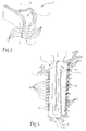
figure 1 is a perspective view, with parts in section and parts removed for clarity, of a first detail of a gas turbine blade; -
figure 2 is a section view, with parts removed for clarity, of the blade infigure 1 ; -
figure 3 is a perspective view, with parts in section and parts removed for clarity, of a detail of a gas turbine blade modified in accordance with the method according to the present invention; -
figure 4 is a section view, with parts removed for clarity, of the blade infigure 3 ; -
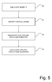
figure 5 is a flow chart of the method for modifying a blade according to the present invention; -
figure 6 is a flow chart of a detail of the method for modifying a blade infigure 5 ; -
figure 7 is a flow chart of a detail of the method for modifying a blade infigure 5 ; -
figure 8 is a flow chart of a detail of the method for modifying a blade infigure 5 ; and -
figure 9 is a flow chart of a detail of the method for modifying a blade infigure 5 . - In
figure 1 ,reference number 1 indicates a blade of a gas turbine (not shown in the accompanying figures for simplicity), which extends along an axis A and is provided with acooling circuit 3 in which a cooling fluid flows. - With reference to
figure 2 , theblade 1 comprises a leadingedge 4, atrailing edge 5, alower base 6, and anupper base 7, opposite to thelower base 6. - The
cooling circuit 3 includes apipe 9, coil-arranged and essentially defined by threesegments exhaust channel 10 arranged on thelower base 6 of theblade 1, and a plurality ofchannels 12, essentially arranged orthogonally to axis A of the blade along thetrailing edge 5 of theblade 1. - The cooling fluid, generally air, enters the
pipe 9 at theupper base 7 of theblade 1, flows in thepipe 9 and exits from theblade 1 through theexhaust channel 10 and the channels 12 (as shown by the arrows in figure). The cooling fluid flow inside thecooling circuit 3 allows to remove heat by convection and thus to lower the external temperature TE of theblade 1. -
Figure 3 shows theblade 1 modified in accordance with the method for modifying a gas turbine blade according to the present invention. Specifically, the modifiedblade 1 includes a plurality offilm cooling holes 16 arranged along the leadingedge 4. In the accompanying figures and in the examples described, thefilm cooling holes 16 are made along the leadingedge 4, which is the most stressed zone from a thermal point of view during the operation of theblade 1 and thus requires a more incisive cooling action. It is understood that the method for modifying a blade, which will be described hereinafter, provides for calculating the optimal configuration, designing and making thefilm cooling holes 16 in each zone of theblade 1 which has shown thermal strength problems. -
Figure 4 shows thecooling circuit 3 of theblade 1 modified in accordance with the method for modifying a blade according to the present invention. Thesegment 9a of the modifiedcooling circuit 3 is directly connected to the throughholes 16. Through theholes 16 the cooling fluid flows, which laps on the external surface of the modifiedblade 1, thus promoting the lowering of the external temperature TE in the zone located about theholes 16. In the case of the example shown in the accompanying figures, the zone of theblade 1 which is externally lapped by the cooling fluid is the leadingedge 4. - With reference to
figure 5 , the method for modifying a gas turbine blade according to the present invention essentially includes the steps of: - calculating a distribution of the external temperature TE of the blade 1 (block 20);
- identifying critical zones of the
blade 1 in which the external temperature TE of the blade exceeds a predetermined limit TL (block 21); - calculating a configuration of a plurality of through
holes 16 to be made in theblade 1 for lowering the external temperature TE in said critical zones below the predetermined limit TL (block 22); and - selectively calculating a new configuration of the
cooling circuit 3 of the blade 1 (block 23). - Preferably, such a method applies to blades which have shown the presence of cracks during the laboratory tests which are normally carried out after approximately 25000 working hours. These tests usually include the use of fluorescent fluids which penetrate into the cracks, thus highlighting them.
- With reference to
figure 6 , for calculating the distribution of the external temperature TE of the blade 1 (block 20), the method firstly includes supplying a numeric model of thecooling circuit 3 of the blade 1 (block 26). Specifically, the numeric model of thecooling circuit 3 is essentially a combination of models (curve, pipe, bottleneck), the fluid-dynamic variable simulation of which is known. - The method then includes measuring a flow rate QM of the cooling fluid flowing in the
cooling circuit 3 of the blade 1 (block 27); preferably, such a measurement is experimentally carried out by connecting theblade 1 to a pressurized circuit (not shown in the accompanying figures) provided with flow rate meters. - Subsequently, the numeric model of the
cooling circuit 3 is calibrated according to the flow rate value QM of the cooling fluid (block 29) and tentative values TET of the external temperature of theblade 1 along a plurality of sections of the blade are determined (block 30). - At this point, the method includes calculating the values of the internal heat exchange coefficient CI and the values of the external heat exchange coefficient CE along the plurality of sections of the blade (block 31). Specifically, the external heat exchange coefficient CE is preferably calculated by means of the fluid-dynamic analysis of the thermal flow between gas and
blade 1, while the internal heat exchange coefficient CI is preferably calculated by means of a one-dimensional thermal analysis to evaluate the thermal flow between cooling fluid andblade 1. - Finally, if the internal heat exchange coefficient CI and the external heat exchange coefficient CE are not the same, the method includes updating the value or the values of the tentative external temperature TET, otherwise the tentative values TET are considered as external temperature TE of the blade 1 (block 33).
- With reference to
figure 7 , the step of calculating the configuration of the plurality of holes 16 (block 22) includes calculating the number N of throughholes 16 and the diameter D of theholes 16 to be made in theblade 1. Specifically, the method provides for determining a tentative diameter value DT of the holes 16 (block 35); determining a tentative number of holes NT (block 36); calculating external temperature values TE of theblade 1 according to the tentative number of holes NT and to the tentative diameter value DT (block 37); updating the tentative number of holes NT if at least one external temperature value TE is higher than the predetermined limit TL and updating the tentative diameter value DT of theholes 16 if at least one external temperature value TE is higher than the predetermined limit TL (critical condition) and if the tentative number of holes NT is higher than a maximum number of holes NL, defined beforehand on the basis of structural considerations. - With reference to
figure 8 , the step of calculating the configuration of the plurality of holes 16 (block 22) may be similarly carried out by firstly determining a tentative number of holes NT (block 50); determining a tentative diameter DT (block 51); calculating the external temperature TE of theblade 1 according to the tentative diameter value DT of theholes 16 and the tentative number of holes NT (block 52); updating the tentative diameter DT if at least one external temperature value TE is higher than the predetermined limit TL and finally updating the tentative number of holes NT if at least one external temperature value TE is higher than the predetermined limit TL and if the tentative diameter value DT is higher than a maximum diameter value DL. - With reference to
figure 9 , once the configuration of a plurality of holes 16 (block 22) has been calculated, the method provides for selectively calculating a new configuration of thecooling circuit 3 of the blade 1 (block 23). Specifically, the calculation of the new configuration of thecooling circuit 3 is carried out if the available flow rate QM of the cooling fluid which is measured on theblade 1 before making theholes 16 is not sufficient for thenew cooling system 3 provided withfilm cooling holes 16. Therefore, the method firstly provides for measuring the available flow rate QM of cooling fluid (block 60); such a measurement is carried out experimentally on theblade 1 which needs to be modified. - Subsequently, the method provides for calculating the requested flow rate QC of the cooling fluid flowing in the
cooling circuit 3 connected to the holes 16 (block 61); such a flow rate QC is calculated considering the previously described numeric model. At this point, if the requested flow rate QC is higher than the available flow rate QM, the method provides for modifying thecooling circuit 3 so that the requested flow rate QC is either lower than or equal to the available flow rate QM. - Specifically, modifying the
cooling circuit 3 includes calculating new tentative passage sections ST of the cooling circuit 3 (block 62) and recalculating the requested flow rate QC (block 61) assuming that the cooling circuit is provided with the new tentative passage sections ST. If the requested, newly calculated flow rate QC is still higher than the available flow rate QM, the tentative passage sections ST are updated (block 62) and the requested flow rate QC is recalculated (block 61). - Once the optimal configuration of the
cooling holes 16 and of thecooling circuit 3 has been obtained, the method provides for makingholes 16 in theblade 1 according to the calculated configuration of theholes 16, and for possibly modifying the sections of thecooling circuit 3 of theblade 1 according to the calculated new configuration of thecooling circuit 3. - The present invention has the following advantages.
- Firstly, in virtue of the method according to the present invention, it is possible to reuse a blade damaged by thermal stresses ensuring its correct cooling in operating conditions. This implies a considerable economic saving because the replace of the damaged blade with a new blade or the frequent repair of the damaged blade is avoided.
- Furthermore, the method according to the present invention is particularly fast and effective for designing the configuration of film cooling holes and of the cooling circuit. Indeed, the method may essentially be fully automated and uses practical and fast calculation tools.
- It is finally apparent that changes and variations may be made to the method described herein without departing from the scope of the appended claims.
Claims (11)
- A method for modifying a gas turbine blade (1) provided with an internal cooling circuit (3) in which a cooling fluid flows; the method being characterized in that it includes the steps of:calculating a distribution of the external temperature (TE) of the blade (1);identifying critical zones of the blade (1) in which the external temperature (TE) of the blade (1) exceeds a predetermined limit (TL);calculating a configuration of a plurality of through holes (16) to be made in the blade (1) and connected to the cooling circuit (3) of the blade (1) for lowering the external temperature (TE) of said critical zones below the predetermined limit (TL).
- A method according to claim 1, characterized in that the step of calculating the configuration of a plurality of holes (16) includes the step of calculating the number (N) of holes (16) and the diameter (D) of the holes (16) to be made in the blade (1).
- A method according to claim 2, characterized in that the step of calculating the number (N) of holes (16) and the diameter (D) of the holes (16) includes the step of determining a tentative diameter value (DT) of the holes (16); determining a tentative number of holes (NT); calculating the external temperature (TE) values of the blade (1) according to the tentative number of holes (NT) and to the tentative diameter value (DT); updating the tentative number of holes (NT) if at least one external temperature value (TE) is higher than the predetermined limit (TL).
- A method according to claim 3, characterized in that the step of calculating the number (N) of holes (16) and the diameter (D) of the holes (16) includes the step of updating the tentative diameter value (DT) if the tentative number of holes (NT) is equal to a maximum number of holes (NL) and if at least one external temperature value (TE) is higher than the predetermined limit (TL).
- A method according to claim 2, characterized in that the step of calculating the number (N) of holes (16) and the diameter (D) of the holes (16) includes the step of determining a tentative number of holes (NT); determining a tentative diameter value (DT); calculating the external temperature values (TE) of the blade (1) according to the tentative diameter value (DT) and to the tentative number of holes (NT); updating the tentative diameter value (DT) if at least one external temperature value (TE) is higher than the predetermined limit (TL).
- A method according to claim 5, characterized in that the step of calculating the number (N) of holes (16) and the diameter (D) of the holes (16) includes the step of updating the tentative number of holes (NT) if the tentative diameter value (DT) is equal to a maximum diameter value (DL) and if at least one external temperature value (TE) is higher than the predetermined limit (TL).
- A method according to anyone of the preceding claims, characterized in that the step of calculating the distribution of the external temperature (TE) of the blade (1) includes the steps of:providing a numeric model for the cooling circuit (3) of the blade (1);measuring a flow rate (QM) of cooling fluid flowing in the cooling circuit (3) of the blade (1);determining a distribution of tentative external temperature values (TET) of the blade (1) along a plurality of sections of the blade (1);calculating the values of the internal heat exchange coefficient (CI) between the blade (1) and the cooling fluid and the values of the external heat exchange coefficient (CE) between the blade (1) and a working fluid in the turbine along the plurality of sections of the blade (1);updating the distribution of the tentative external temperature values (TET) of the blade (1) if the external heat exchange coefficient (CE) is different from the internal heat exchange coefficient (CI).
- A method according to anyone of the preceding claims, characterized in that it includes the step of selectively calculating a new configuration of the cooling circuit (3) of the blade (1).
- A method according to claim 8, characterized in that the step of selectively calculating a new configuration of the cooling circuit (3) of the blade (1) includes:measuring an available flow rate (QM) of cooling fluid flowing in the cooling circuit (3) of the blade (1);measuring a requested flow rate (QC) of cooling fluid flowing in the cooling circuit (3) connected to the holes (16);if the requested flow rate (QC) is higher than the available flow rate (QM), modifying the cooling circuit(3) so that the requested flow rate (QC) is lower than or equal to the available flow rate (QM).
- A method according to claim 9, characterized in that the step of modifying the cooling circuit (3) includes the steps of calculating new tentative passage sections (ST) of the cooling circuit (3); calculating the requested flow rate (QC) in the modified cooling circuit (3) with the new tentative passage sections (ST); updating the new tentative passage sections (ST) of the cooling circuit (3) if the requested flow rate (QC) is higher than the available flow rate (QM).
- A method according to anyone of the preceding claims, characterized in that it includes the step of making the holes (16) according to the calculated configuration.
Applications Claiming Priority (1)
| Application Number | Priority Date | Filing Date | Title |
|---|---|---|---|
| ITMI20071564 ITMI20071564A1 (en) | 2007-07-31 | 2007-07-31 | METHOD TO MODIFY A SHOVEL OF A GAS TURBINE |
Publications (1)
| Publication Number | Publication Date |
|---|---|
| EP2025870A2 true EP2025870A2 (en) | 2009-02-18 |
Family
ID=40001382
Family Applications (1)
| Application Number | Title | Priority Date | Filing Date |
|---|---|---|---|
| EP20080161606 Withdrawn EP2025870A2 (en) | 2007-07-31 | 2008-07-31 | Method for modifying a gas turbine blade |
Country Status (2)
| Country | Link |
|---|---|
| EP (1) | EP2025870A2 (en) |
| IT (1) | ITMI20071564A1 (en) |
Cited By (1)
| Publication number | Priority date | Publication date | Assignee | Title |
|---|---|---|---|---|
| CN104088671A (en) * | 2014-07-10 | 2014-10-08 | 东北电力大学 | Air film cooling effect orthogonality prediction method based on multi-parameter influences |
-
2007
- 2007-07-31 IT ITMI20071564 patent/ITMI20071564A1/en unknown
-
2008
- 2008-07-31 EP EP20080161606 patent/EP2025870A2/en not_active Withdrawn
Cited By (2)
| Publication number | Priority date | Publication date | Assignee | Title |
|---|---|---|---|---|
| CN104088671A (en) * | 2014-07-10 | 2014-10-08 | 东北电力大学 | Air film cooling effect orthogonality prediction method based on multi-parameter influences |
| CN104088671B (en) * | 2014-07-10 | 2016-01-20 | 东北电力大学 | Based on the Film Cooling orthogonal predictor method under effect of multiple parameters |
Also Published As
| Publication number | Publication date |
|---|---|
| ITMI20071564A1 (en) | 2009-02-01 |
Similar Documents
| Publication | Publication Date | Title |
|---|---|---|
| EP2679778B1 (en) | A method for measuring geometry deformations of a turbine component | |
| CN113188781B (en) | Method for correcting rotor temperature field in fatigue test of blade of aircraft engine | |
| CN107084844A (en) | A kind of test method of blade construction simulating piece | |
| KR20120034799A (en) | Automated repair method and system | |
| EP2540962A2 (en) | Method for forming nozzle segments | |
| JP6883121B2 (en) | Extending the life of power turbine disks that are corroded and damaged during operation | |
| CN114235319B (en) | Hollow turbine blade test device and method | |
| CN105043914A (en) | Test method and device for evaluating thermal fatigue of high-temperature alloy | |
| CN118391962A (en) | Enhanced heat transfer method of shell-and-tube heat exchanger | |
| EP2025870A2 (en) | Method for modifying a gas turbine blade | |
| CN106181220B (en) | Flame repairing technique after a kind of aluminum alloy welding | |
| CN115758603A (en) | Method for predicting multi-working-condition creep/stress rupture life of turbine blade of aircraft engine | |
| US7970555B2 (en) | Method for developing a repair process to correct a deformed gas turbine engine component | |
| EP2975314B1 (en) | Method of extending life expectancy of high-temperature piping and life expectancy extension structure of high-temperature piping | |
| CN103470314A (en) | Method and system for determining creep capability of turbine components prior to operation | |
| US8322202B2 (en) | Method for inspecting a turbine installation and corresponding device | |
| JPH09195795A (en) | Method and apparatus for evaluating remaining life of gas turbine stationary blade | |
| CN115533231B (en) | High-vortex blade tenon cooling hole supplementing and processing method | |
| JP2019157832A (en) | Repair determination device for gas turbine stationary blade and repair determination method for gas turbine stationary blade | |
| CN113029075B (en) | Method for rapidly judging aging damage degree of high-temperature austenitic steel furnace tube for thermal power plant on site | |
| DE102004002965A1 (en) | Method and apparatus for repairing integrally bladed rotors | |
| CN114813329A (en) | A residual life prediction method for nickel-based single crystal superalloys under random creep loading | |
| JP3303685B2 (en) | Structural component maintenance management device and maintenance management method | |
| JPH02136713A (en) | Diagnostic system for plant facility | |
| CN113235461B (en) | Method for repairing suspension bridge cable clamp ear hole and box girder ear hole |
Legal Events
| Date | Code | Title | Description |
|---|---|---|---|
| PUAI | Public reference made under article 153(3) epc to a published international application that has entered the european phase |
Free format text: ORIGINAL CODE: 0009012 |
|
| AK | Designated contracting states |
Kind code of ref document: A2 Designated state(s): AT BE BG CH CY CZ DE DK EE ES FI FR GB GR HR HU IE IS IT LI LT LU LV MC MT NL NO PL PT RO SE SI SK TR |
|
| AX | Request for extension of the european patent |
Extension state: AL BA MK RS |
|
| STAA | Information on the status of an ep patent application or granted ep patent |
Free format text: STATUS: THE APPLICATION IS DEEMED TO BE WITHDRAWN |
|
| 18D | Application deemed to be withdrawn |
Effective date: 20130201 |