EP2025817A2 - Guardrail - Google Patents
Guardrail Download PDFInfo
- Publication number
- EP2025817A2 EP2025817A2 EP20080019591 EP08019591A EP2025817A2 EP 2025817 A2 EP2025817 A2 EP 2025817A2 EP 20080019591 EP20080019591 EP 20080019591 EP 08019591 A EP08019591 A EP 08019591A EP 2025817 A2 EP2025817 A2 EP 2025817A2
- Authority
- EP
- European Patent Office
- Prior art keywords
- impact
- guardrail
- cable
- rail
- rails
- Prior art date
- Legal status (The legal status is an assumption and is not a legal conclusion. Google has not performed a legal analysis and makes no representation as to the accuracy of the status listed.)
- Granted
Links
- 230000033001 locomotion Effects 0.000 abstract description 19
- 238000000034 method Methods 0.000 abstract description 9
- 238000004873 anchoring Methods 0.000 abstract description 7
- 230000003116 impacting effect Effects 0.000 description 8
- 239000000463 material Substances 0.000 description 6
- 230000004888 barrier function Effects 0.000 description 5
- 239000002689 soil Substances 0.000 description 5
- 229910000831 Steel Inorganic materials 0.000 description 4
- 230000021715 photosynthesis, light harvesting Effects 0.000 description 4
- 229920003023 plastic Polymers 0.000 description 4
- 239000004033 plastic Substances 0.000 description 4
- 125000006850 spacer group Chemical group 0.000 description 4
- 239000010959 steel Substances 0.000 description 4
- 230000037361 pathway Effects 0.000 description 3
- 238000010521 absorption reaction Methods 0.000 description 2
- 239000002131 composite material Substances 0.000 description 2
- 238000013270 controlled release Methods 0.000 description 2
- 230000000694 effects Effects 0.000 description 2
- 230000008569 process Effects 0.000 description 2
- 230000009467 reduction Effects 0.000 description 2
- 238000011144 upstream manufacturing Methods 0.000 description 2
- 229910001209 Low-carbon steel Inorganic materials 0.000 description 1
- 238000007792 addition Methods 0.000 description 1
- 238000005452 bending Methods 0.000 description 1
- 238000010276 construction Methods 0.000 description 1
- 230000026058 directional locomotion Effects 0.000 description 1
- 238000005516 engineering process Methods 0.000 description 1
- 230000009191 jumping Effects 0.000 description 1
- 238000012986 modification Methods 0.000 description 1
- 230000004048 modification Effects 0.000 description 1
- 230000000149 penetrating effect Effects 0.000 description 1
- 230000001681 protective effect Effects 0.000 description 1
- 238000000926 separation method Methods 0.000 description 1
- 230000003313 weakening effect Effects 0.000 description 1
Images


Classifications
-
- E—FIXED CONSTRUCTIONS
- E01—CONSTRUCTION OF ROADS, RAILWAYS, OR BRIDGES
- E01F—ADDITIONAL WORK, SUCH AS EQUIPPING ROADS OR THE CONSTRUCTION OF PLATFORMS, HELICOPTER LANDING STAGES, SIGNS, SNOW FENCES, OR THE LIKE
- E01F15/00—Safety arrangements for slowing, redirecting or stopping errant vehicles, e.g. guard posts or bollards; Arrangements for reducing damage to roadside structures due to vehicular impact
- E01F15/02—Continuous barriers extending along roads or between traffic lanes
- E01F15/06—Continuous barriers extending along roads or between traffic lanes essentially made of cables, nettings or the like
-
- E—FIXED CONSTRUCTIONS
- E01—CONSTRUCTION OF ROADS, RAILWAYS, OR BRIDGES
- E01F—ADDITIONAL WORK, SUCH AS EQUIPPING ROADS OR THE CONSTRUCTION OF PLATFORMS, HELICOPTER LANDING STAGES, SIGNS, SNOW FENCES, OR THE LIKE
- E01F15/00—Safety arrangements for slowing, redirecting or stopping errant vehicles, e.g. guard posts or bollards; Arrangements for reducing damage to roadside structures due to vehicular impact
- E01F15/02—Continuous barriers extending along roads or between traffic lanes
- E01F15/025—Combinations of at least two of the barrier member types covered by E01F15/04 - E01F15/08, e.g. rolled steel section or plastic strip backed up by cable, safety kerb topped by rail barrier
-
- E—FIXED CONSTRUCTIONS
- E01—CONSTRUCTION OF ROADS, RAILWAYS, OR BRIDGES
- E01F—ADDITIONAL WORK, SUCH AS EQUIPPING ROADS OR THE CONSTRUCTION OF PLATFORMS, HELICOPTER LANDING STAGES, SIGNS, SNOW FENCES, OR THE LIKE
- E01F15/00—Safety arrangements for slowing, redirecting or stopping errant vehicles, e.g. guard posts or bollards; Arrangements for reducing damage to roadside structures due to vehicular impact
- E01F15/14—Safety arrangements for slowing, redirecting or stopping errant vehicles, e.g. guard posts or bollards; Arrangements for reducing damage to roadside structures due to vehicular impact specially adapted for local protection, e.g. for bridge piers, for traffic islands
- E01F15/143—Protecting devices located at the ends of barriers
Definitions
- This invention relates to guardrails and in particular, though not solely, to guardrails and/or guardrail impact heads for use in roading networks and/or vehicle road lanes requiring separation by a barrier.
- Existing highway guardrail end treatment systems include: the breakaway cable terminal (BCT), the eccentric loader terminal (ELT), the modified eccentric loader terminal (MELT), the vehicle attenuating terminal (VAT), the extruder terminal (ET 2000 and ET plus), the slotted rail terminal (SRT), the sequential kinking terminal (SKT) and the flared energy absorbing terminal (FLEAT).
- Terminal ends that is, the end facing oncoming traffic
- Terminal ends generally consist of one or more, often three, W shaped (in cross-section) guardrails supported by a series of both controlled release terminal (CRT) or frangible posts and standard highway guardrail posts.
- CRT controlled release terminal
- a cable assembly arrangement is utilised that anchors the end of the rail to the ground, transferring tensile load developed in a side-on impact by an errant vehicle to the ground anchor.
- the terminal ends have an impact head arrangement that will be the first part impacted by an errant vehicle during an end-on impact which is designed to spread or absorb some of the impact energy.
- Some terminal ends such as the abovementioned ET, SKT and FLEAT, absorb the energy of the impacting vehicle during an end on impact by having an impact head that slides down the W shaped guardrails, extruding it and breaking away the support posts as it travels down the rails. All of the other abovementioned terminal ends work on the principal of various weakening devices in the posts and rails to allow an errant vehicle to penetrate the terminal end in a controlled manner and prevent the rails from spearing the vehicle or the vehicle from vaulting or jumping over a relatively stiff terminal end.
- guardrail terminal ends are considered to be gating, that is, if impacted between the impact head and the "length of need" (where the "length of need” is considered to be the distance from the terminal end to where the guardrail will redirect a vehicle during an angled impact) during an angled impact, the terminal end will gate and allow the errant vehicle to pass to the back side of the terminal end.
- this gating effect may have undesirable or unsafe results, and preferably an improved or safer or varied energy absorbing system is utilised to control errant vehicle barrier/guardrail impacts.
- the invention provides an impact head for a guardrail including cable routing means configured to form a tortuous path through which a cable can be threaded.
- the cable routing means for use in the impact head according to the invention may be any member through which a cable may pass and that provides a tortuous path through which said cable may be threaded.
- the tortuous path may be any path that provides sufficient friction to slow down the movement of the impact head during a vehicle impact.
- the tortuous nature of the passage through the cable routing means may be provided by one or more turns through which a cable may be threaded.
- the tortuous nature of the passage through the cable routing means may be provided by one or more turns of greater than substantially 90° through which a cable may be threaded.
- the cable routing means includes at least one substantially 180° turn.
- the cable routing means includes at least one substantially S or Z-shaped turn.
- the cable routing means may be adapted so that in use and during a collision or impact with the impact head, the cable is forced through the cable routing means, where resistance to cable movement provided by the tortuous cable path substantially facilitates impact energy dissipation.
- the cable routing means is adapted so that when a predetermined level of force is applied to the impact head the one or more cables are forced through the cable routing means, where resistance to cable movement provided by the tortuous cable path limits any movement of the impact head caused by the force.
- the cable routing means may include a member having two or more cable entry ports provided therein through which a cable may be threaded.
- the cable routing means comprises a bar member having a longitudinal axis and including a cable entry port adapted to allow a cable to pass directly therethrough when said bar member is in a first non-cable-gripping orientation, and wherein upon rotation of said bar member through at least 90° about said longitudinal axis, a second cable-gripping orientation is reached.
- the cable may be anchored at one point, pass through the impact head according to the invention and then be anchored at another point such that the impact head is substantially between the two anchor points.
- the cables may be anchored to any object capable of providing sufficient inertia to restrict cable movement.
- the cables may be either directly or indirectly anchored to the ground.
- the bar member may be secured in the second orientation by locking means in the form of bolts, screws and the like.
- the impact head and/or guardrail according to the present invention may be manufactured from any resilient or impact resistant material or composite of materials of any nature.
- the impact head and/or the guardrail may be constructed from steel.
- one or more cables may be threaded through the cable routing means. These cables may preferably be tensioned and anchored at one or more points. In those embodiments where the cable (s) is/are anchored, they may be preferably anchored at one end via a rail and/or a support post of the guardrail.
- the one or more cables may be anchored at one end in a position upstream of the proposed traffic flow from the impact head and the other end (s) may be anchored to a rail and/or a support post.
- the cable may be high-tensile steel.
- the tension of one or more cables may be adjusted so as to give a suitable resistant to movement.
- the present invention also provides a guardrail including:
- the support posts for use in the guardrail according to the present invention may be made of any suitable material.
- the support posts may be made from treated timber.
- At least some of the support posts may have a predetermined failure load
- the at least one cable may be located within recesses within the plurality of a slidably interconnected rails.
- the support posts of predetermined failure load may have a substantially horizontal region of weakness.
- the present invention also provides a guardrail including:
- the support post has a greater failure load than that of the predetermined failure load support posts.
- the slidably connected rails telescope upon an impact substantially in-line with the longitudinal direction of the slidable rails.
- the rails are separated from the support posts by a spacer.
- frangible fasteners connect a plurality of rails to one another and/or to said posts.
- the impact slider means is attached to the end of a first rail at or near a connection with a second rail, wherein the impact slider device is slidable along the second rail.
- the movement of the impact slider means along the second rail disconnects the second rail from its associated post or posts.
- the impact head or the cable routing means may be mounted to a first support post or to a rail.
- the cable routing means is connected to an end of a plurality of interconnected rails.
- the impact slider of certain aspects of the present invention may, in use, impact the rail and post connections and disconnect the rail and post.
- the impact slider may be of any shape but in preferred embodiments substantially conforms with the rail profile.
- the means for gathering and retaining the impact slider includes telescoping during an impact.
- the means for gathering and retaining is a pair of L-shaped arms extending rear-wardly from the impact slider, in the direction of the support post.
- the cable routing means is mounted on a first post
- the impact slider device is attached to the end of a first rail, wherein the impact slider device is slidable along a second rail overlapping the end of the first rail.
- the invention may broadly be said to consist in a frangible fastener comprising:
- the frangible zone is formed by the convergence of a tapered reduction in the cross-sectional diameter of the shank portion.
- the frangible zone is located within the ends of the shank portion.
- the frangible fastener structurally fails substantially at the frangible zone upon a force loading in shear to the frangible fastener's longitudinal axis.
- the frangible fastener comprises a threaded securing means.
- the invention may broadly be said to consist in a frangible post comprising:
- first and second members are integral or welded together.
- the first and second members are connected in one of the following configurations: an L-beam, an I-beam, an X-beam or a T-beam.
- two first members are connected to said second member in an I-beam configuration.
- the post is sunk into the ground, with the at least one region of weakness being near or at ground level.
- rotation of the bar member from said first orientation to said second orientation ensures that the cable follows a tortuous pathway.
- the present invention also relates to a method of constructing a guardrail including the steps of slidably interconnecting a plurality of rails and attaching them to posts, positioning an impact head according to the invention at one end of the slidably interconnected rails, threading at least one cable through the impact head and anchoring the cable to the ground.
- This invention is designed to be a substantially non-gating guardrail, meaning that at any point along the side of the guardrail from the terminal end onwards, an impacting vehicle on an angled collision may be substantially redirected away from its initial impact trajectory. It is also designed to substantially absorb energy during an end on impact to the terminal end.
- Treating is a term used within the guardrail industry to refer to sections of guardrail which are unable to withstand high impact side angle collisions, and significant guardrail deformation or ultimate failure or breakage may occur.
- Figures 1 a and 1 b will be referred together as Figure 1 ; similarly Figures 2a and 2b will be referred to as Figure 2 .
- the guardrail 1 shown has been split into two sections for illustrative purposes only, and sections A and A' in Figures 1 a and 1b; and the same sections are labelled B and B' in Figures 2a and 2b should be joined to show an embodiment the guardrail according to the present invention.
- a guardrail 1 with a cable routing or gripping means 2 at the terminal end.
- the cable gripping means 2 may form part of an impact head (where an impact head is an additional guardrail bumper used to initially absorb some impact energy).
- the cable gripping means 2 (and optionally impact head) may be bolted to the first rail 3, at the other end of which is connected an impact slider device 4.
- the impact slider device 4 may facilitate the sliding of the first rail over each subsequent rail, thereby providing substantial telescoping ability to the guardrail, with each rail overlapping the next rail to enable this process during an end-on impact.
- the impact slider device may substantially surround the first rail and advantageously includes a portion 31 which gathers and retains telescoping railings during an impact.
- the rails 3, 5, 6 may be supported by upstanding CRT (controlled release terminal) 7a, 7b, 7c, 7d and/or frangible posts and/or posts of a predetermined failure load or any combination of these post types.
- the rails may be directly attached to the posts, or alternatively may be indirectly attached via a spacer 17 or similar block type arrangement.
- the impact slider device 4 may also be used to detach or facilitate the disjointing or disconnection of a connection such as bolt 8 between a rail 5 and a support post 7.
- a connection such as bolt 8 between a rail 5 and a support post 7.
- the impact slider device 4 is a structural member of suitable strength that allows the bolts 8 (or similar connector) connecting rail 5 to posts 7a - 7g; or rail 5 to rail 3 or the next rail 6; to either be severed from the rail or pulled or bent free from the rail connection.
- the rails 3, 5, 6 may be connected to each other separately from support post connections.
- the bolts 8 may be made of materials such as plastics or high density plastic or other composite materials, or frangible bolts, which are more likely to fail and be sheared off from the post connection (or from the rail to rail connection) by an impact from the slider, than a side angle impact with the guardrails. This may be an advantageous feature allowing the slider to operate and shear off post holding rail bolts 8, whilst at the same time providing resistance to side angle impacts and reducing the likelihood of the guardrail gating.
- a fastener 8 composed of high strength materials or even a "standard" mild steel bolt could be structurally altered to provide frangible characteristics.
- an alternative frangible fastener 8 is shown in Figure 7 .
- the frangible bolt includes a head portion 18, a tail portion 19 with a shank portion 20 therebetween.
- the head portion has a minimum cross-sectional diameter 21 greater than the maximum cross-sectional diameter of the tail portion, and the shank portion includes a frangible zone 22 having a minimum cross-sectional diameter smaller than the tail portion's maximum cross-sectional diameter 23.
- the frangible zone can be formed by the convergence of a tapered reduction in the cross-sectional diameter of the shank portion, with the frangible zone being located in the shank portion.
- the frangible fastener may structurally fail substantially at the frangible zone upon a force loading in shear direction X, to the frangible fastener's axial direction, that is, at an orthogonal direction to the fastener's longitudinal or axial direction.
- the frangible fastener is a bolt, screw or similar threaded securing means.
- a securing means can be used to connect the guardrail rails to the support posts, and may be especially suitable for use with the guardrail slider device.
- the slider can impact the frangible fastener holding the rails onto the support posts, the fastener will be subjected to a shear force or impacting force, and as a consequence of the weakened fastener shank portion, the fastener can break (or structurally fail).
- an impact with the fastener in a direction in-line with the longitudinal axis, that is in direction Y, of the fastener is less likely to induce fastener failure, as the impacting force is transferred down the length of the fastener and is not exposed to any regions of frangibility or weakness.
- the frangible bolt as illustrated in Figure 7 should preferably have a 6mm shank length, 16mm tail cross-sectional diameter, and an 8.5mm cross-sectional diameter at the narrowest section of the frangible zone.
- a cable 15 has an end 10 which may be attached to a soil anchor assembly or fixed such as at 11, at the terminal end of the guardrail.
- the other cable end 11a extends to a second anchor or fixed point 12, which may be a further soil anchor assembly, or alternatively, may be an anchoring assembly attached to a non-frangible support post or non-telescoping rail.
- the cable 15 may be anchored by cable brackets 13 to the posts or rails or by any suitable cable anchoring system, such as bolts and welds or the like.
- the soil anchor assembly arrangement may include a sunken post (or I-beam) with flares or winged portions 18 extending outwards from the post to engage with greater soil area and providing increased resistance to movement of the anchor assembly as a result of an impact with the guardrail.
- FIG. 1 and 2 of a guardrail system consists of a soil anchoring system 11 at the terminal end of the guardrail and provides a means to attach two cables 15, 15a thereto.
- the cables are preferably threaded in a substantially S-shape (or Z-shape), through the cable gripping means 2, which may be a steel plate bolted to the terminal end of a length of rail 3 (or first post 7a).
- the cable gripping means 2 which may be a steel plate bolted to the terminal end of a length of rail 3 (or first post 7a).
- the cables 15, 15a after being threaded through the cable gripping means 2, are positioned in a hollow or recess 14 of the back side of the length of the rail (for example, the rail may be a W-shaped beam).
- the cables may extend until a point 11a where they may be anchored to the rail (or post, or other anchoring means) at a post downstream of the cable gripping means 2 using one or more cable brackets 13 or other connecting and/or cable fixing means.
- Such means may be screw bolts, welded joints or other suitable devices enabling substantially secure cable anchoring.
- the cable may be tensioned, although this is not essential for the present invention to operate.
- the impact head 24 includes: at least one cable routing means through which a cable is threaded in a tortuous path and which thereby provides resistance to cable movement therethrough.
- the path of the cable through the cable routing means includes at least one substantially 180° turn, or is in a substantially S or Z-shape.
- the at least one cable is forced through the cable gripping means 2, where resistance to cable movement substantially facilitates impact energy dissipation.
- the cable routing means may be a planar bar member 25 adapted to receive and allow at least one cable to pass therethrough via at least three cable entry ports in series which are formed therein, forming the tortuous path which provides resistance to cable movement therethrough, such as is illustrated in Figures 1 a and 2a.
- a bar member 25 can be provided with a cable entry port or ports P1, P2 adapted to receive and allow at least one cable to pass directly therethrough, when said bar member is in a first non-cable-gripping orientation 26. Subsequently, upon rotation of the bar member about its longitudinal axis (substantially perpendicular to the cables length) through at least 90°, a second cable-gripping orientation 27 is reached.
- the bar member may be secured in the second orientation by locking means (not shown), such as by bolts or screws.
- the rotation of the bar member 25 from said first orientation to the second orientation ensures that the at least one cable follows a tortuous pathway.
- the rotation of the bar member 25 may be undertaken, for example by a crow bar inserted into a slot, S1, and then an angular or rotational force applied.
- support post (7a) In use, energy from a head on impact with the impact head/cable gripping means 2 is initially substantially absorbed by support post (7a), which may subsequently fail, preferably substantially at or near ground level 16.
- the first support post 7a would normally be impacted at or by the impact head/cable gripping means, and absorb energy before preferably failing (that is, being broken). Should a support post fail and be broken off at a height substantially above ground level than that would contact the impacting vehicle and then the vehicle may collide with the broken post and result in more severe impact energy absorption (possibly resulting in vehicle occupant damage due to sudden movement arrest).
- each support post is impacted by the slider device 4 and preferably causes breakaway of the posts.
- a guardrail may also be provided in which just an impact slider is connected to the rails, and no cable gripping means or impact head is attached.
- the guardrail system employs energy absorption/dissipation systems which substantially control an impacting object momentum and directional motion.
- energy may be absorbed or dissipated by the friction between the cable 15 and cable gripping means 2.
- the guardrail is impacted end on (that is, in the substantially longitudinal direction of the guardrail and impacting the impact head and/or cable gripping means initially)
- the whole of rail 3 the impact head/cable gripping means 2 and the impact slider device 4 move back in a telescoping manner over rail 5 and then subsequent downstream rails, such as rail 5 and/or rail 6.
- Energy is also absorbed by the friction of the cables 15 running through the cable gripping means 2, wherein the threaded cable configuration through the cable routing means follows the tortuous pathway.
- the cable gripping means 2 is attached to or forms an integral part of a bumper or impact head, as the impact head and cable gripping means move (as a result of an end-on impact with the impact head/guardrail), away from the cable anchor point 11, the cable gripping means is effectively forced to move along the cable(s), whilst the cable(s) 15, 15a remain substantially stationary as a result of being fixed at each of their ends. In doing so, the cable is forced through a number of bending movements created by the threading configuration in the cable gripping means.
- the cable used has substantial resistance to flexing (such as steel cable), and energy is dissipated from the impact and imparted to energy used to bend the cable.
- the cable gripping means 2 may be in the form of a sleeve fitted around the cable 15, 15a, which is snug around the cable and provides frictional resistance to relative movement of either the sleeve or cable.
- the friction created by the impact slider device 4 (and rails 3, 5, 6) moving over one another during an impact event may help to absorb energy.
- the impacting object is redirected away from the guardrail 1 and the forces generated by the impact are distributed throughout the rails and cables either by deformation or tension generated in the cables and subsequently redirected to the cable fixing point.
- a number of support posts 7a-7g may be frangible or of a predetermined failure load which fail or substantially deform, consequently absorbing further impact energy.
- an object such as a vehicle, involved in a side angle impact is substantially redirected away from the guardrail, and back onto the road, and the guardrail itself is restrained from “gating" by the further tension created in the cables by the impacts induced lateral cable movement.
- a frangible post construction as illustrated in Figure 8 may be especially suitable for re-directing an errant side-impacting vehicle back onto the road.
- the frangible post has a first member 28 connected substantially orthogonally to a second member 29.
- the first member is provided with at least one region of weakness 30.
- this configuration allows a substantially frangible or weakened region to exist in the first member which may be more likely to be structurally affected during an impact, for example in direction T.
- an impact in line with the second member will require a greater impact force to structurally affect the second member or post, for example in direction U.
- the post will tend to bend or break at the weakened region when subjected to that force.
- the region of weakness in the first member has little effect on the frangibility of the post and the second member offers substantial resistance to deflection in that direction.
- the first and second members need not be attached to one another at exactly 90°, however this orientation may be most suitable for use with a guardrail where impacts are generally received either in-line with the longitudinal axis of the guardrail, or substantially perpendicular to the guardrail.
- the frangible post is designed to more easily structurally fail in an impact from a direction substantially in line with the longitudinal axis of the guardrail than in an impact substantially perpendicular to the guardrail.
- the at least one region of weakness can be formed by a cut-away section 30 from the first member, or other similar notches or portions of the first member being removed.
- the frangible post formed may be selected from the following configurations: an I-beam, an L-beam, an X-beam, a T-beam, a Z-beam. The configuration chosen may depend on the post geometry required by a user.
- the first and second members are preferably integrally formed or welded together.
- each post is sunk into the ground, with the at least one region of weakness being at or near to ground level; which allows the post to break off at or near ground level during a post failure impact.
- an I-beam configuration of the post as illustrated in Figure 8b should be aligned so that the first members are parallel with the road (and therefore guardrail).
- Each edge of the first member having a 12mm deep triangular notch removed from the first member, the first member of which has dimensions (excluding length) is about 100mm in width, and of about 20mm thickness.
- Such notches should preferably be made so that they are approximately 50mm below ground level (after the post has been "sunk").
- a tear in the first member starts in the upstream note from the impact, while the downstream notch allows the first member to collapse and/or fail.
- the guardrail as described above may be utilised in applications where protective barriers are required to separate vehicle traffic flow from each other, or safety to pedestrians from vehicles, or even to protect vehicles running off roads. It is desirable that the guardrail as described provides a non-gating design and which re-directs an errant vehicle from its correct path back onto a road or at least away from pedestrians on a footpath.
- the guardrail as described goes at least some way toward facilitating a system for controllably slowing a vehicle during an end-on barrier impact, as well as some way towards preventing the guardrail from gating during a side angled impact. It is also preferable that the "length of need" is substantially reduced compared to various existing technologies, and may most preferably have a length of need of almost zero distance.
- the guardrail as described may be utilised to form a part of whole of a guardrail system, although this system in particular may be applied to the terminal ends of a required guardrail or barrier or be substantially retrofit-able to existing guardrails.
- Figure 10 shows an impact slider which includes means for attachment to a first rail in the form of a slider (33) which substantially conforms with the rail profile and with integral means for attachment to said first rail in the form of slotted holes (34) through which, in one preferred embodiment, fasteners may be passed and secured to said first rail.
- the angle bar shown (32) in figure 9 may butt up against one end of the impact slider so as to hold the first rail (not shown in figures 9 and 10 but shown in figure 11 ) within the impact slider, thereby providing support via the support post and spacer (if present).
- the impact slider bracket (30) also has means for attachment (31) via fasteners to the second rail, although this is a preferred embodiment and, in other embodiments, the impact slider bracket may be attached only to the second rail, or to both the first and second rail.
- the impact slider may cause the impact slider bracket to come free of the support post by breaking the frangible fastening of the impact slider bracket to the support post (whether via a spacer or not).
- the impact slider bracket (33) still surrounds both the first and second rail it may gather telescoping rails approaching from the left hand side in figure 11 whilst maintaining or at least substantially maintaining the rails in a "non-gating" configuration, that is, that the first rail (that shown on the left hand side of figure 11 ) may move substantially along the length of rail to (shown on the right in figure 11 ) so that a vehicle approaching from the traffic side of the rail (the top left hand corner as viewed in figure 11 ) has a low probability of penetrating through to the protected side (the bottom right corner as shown in figure 11 ) and thereby preventing "gating" of the rails.
- the L shaped angle bracket (32) is attached to the impact slider bracket (30) and upon side impacts on the rails, prevents the joint between rails one and two from separating. This is achieved by the L shaped angle bracket (32) being larger than the slider (33) and therefore being unable to pass through the slider (33).
Abstract
Description
- This invention relates to guardrails and in particular, though not solely, to guardrails and/or guardrail impact heads for use in roading networks and/or vehicle road lanes requiring separation by a barrier.
- Existing highway guardrail end treatment systems include: the breakaway cable terminal (BCT), the eccentric loader terminal (ELT), the modified eccentric loader terminal (MELT), the vehicle attenuating terminal (VAT), the extruder terminal (ET 2000 and ET plus), the slotted rail terminal (SRT), the sequential kinking terminal (SKT) and the flared energy absorbing terminal (FLEAT).
- Terminal ends (that is, the end facing oncoming traffic) generally consist of one or more, often three, W shaped (in cross-section) guardrails supported by a series of both controlled release terminal (CRT) or frangible posts and standard highway guardrail posts. Generally a cable assembly arrangement is utilised that anchors the end of the rail to the ground, transferring tensile load developed in a side-on impact by an errant vehicle to the ground anchor. Generally the terminal ends have an impact head arrangement that will be the first part impacted by an errant vehicle during an end-on impact which is designed to spread or absorb some of the impact energy.
- Some terminal ends such as the abovementioned ET, SKT and FLEAT, absorb the energy of the impacting vehicle during an end on impact by having an impact head that slides down the W shaped guardrails, extruding it and breaking away the support posts as it travels down the rails. All of the other abovementioned terminal ends work on the principal of various weakening devices in the posts and rails to allow an errant vehicle to penetrate the terminal end in a controlled manner and prevent the rails from spearing the vehicle or the vehicle from vaulting or jumping over a relatively stiff terminal end.
- All of the abovementioned guardrail terminal ends are considered to be gating, that is, if impacted between the impact head and the "length of need" (where the "length of need" is considered to be the distance from the terminal end to where the guardrail will redirect a vehicle during an angled impact) during an angled impact, the terminal end will gate and allow the errant vehicle to pass to the back side of the terminal end. However this gating effect may have undesirable or unsafe results, and preferably an improved or safer or varied energy absorbing system is utilised to control errant vehicle barrier/guardrail impacts.
- It is therefore an object of the present invention to provide a guardrail and/or guardrail impact head which will go at least some way towards addressing the foregoing problems or which will at least provide the industry with a useful choice.
- All references, including any patents or patent applications cited in this specification are hereby incorporated by reference. No admission is made that any reference constitutes prior art. The discussion of the references states what their authors assert, and the applicants reserve the right to challenge the accuracy and pertinency of the cited documents. It will be clearly understood that, although a number of prior art publications are referred to herein, this reference does not constitute an admission that any of these documents form part of the common general knowledge in the art, in New Zealand or in any other country.
- It is acknowledged that the term 'comprise' may, under varying jurisdictions, be attributed with either an exclusive or an inclusive meaning. For the purpose of this specification, and unless otherwise noted, the term 'comprise' shall have an inclusive meaning - i.e. that it will be taken to mean an inclusion of not only the listed components it directly references, but also other non-specified components or elements. This rationale will also be used when the term 'comprised' or 'comprising' is used in relation to one or more steps in a method or process.
- Further aspects and advantages of the present invention will become apparent from the ensuing description which is given by way of example only.
- Accordingly, in a first aspect, the invention provides an impact head for a guardrail including cable routing means configured to form a tortuous path through which a cable can be threaded.
- The cable routing means for use in the impact head according to the invention may be any member through which a cable may pass and that provides a tortuous path through which said cable may be threaded. The tortuous path may be any path that provides sufficient friction to slow down the movement of the impact head during a vehicle impact.
- The tortuous nature of the passage through the cable routing means may be provided by one or more turns through which a cable may be threaded.
- In preferred embodiments the tortuous nature of the passage through the cable routing means may be provided by one or more turns of greater than substantially 90° through which a cable may be threaded.
- In preferred embodiments the cable routing means includes at least one substantially 180° turn.
- In particularly preferred embodiments the cable routing means includes at least one substantially S or Z-shaped turn.
- In some embodiments the cable routing means may be adapted so that in use and during a collision or impact with the impact head, the cable is forced through the cable routing means, where resistance to cable movement provided by the tortuous cable path substantially facilitates impact energy dissipation.
- In particularly preferred embodiments the cable routing means is adapted so that when a predetermined level of force is applied to the impact head the one or more cables are forced through the cable routing means, where resistance to cable movement provided by the tortuous cable path limits any movement of the impact head caused by the force.
- In some embodiments the cable routing means may include a member having two or more cable entry ports provided therein through which a cable may be threaded.
- Preferably, the cable routing means comprises a bar member having a longitudinal axis and including a cable entry port adapted to allow a cable to pass directly therethrough when said bar member is in a first non-cable-gripping orientation, and
wherein upon rotation of said bar member through at least 90° about said longitudinal axis, a second cable-gripping orientation is reached. - In preferred embodiments the cable may be anchored at one point, pass through the impact head according to the invention and then be anchored at another point such that the impact head is substantially between the two anchor points.
- The cables may be anchored to any object capable of providing sufficient inertia to restrict cable movement.
- In preferred embodiments the cables may be either directly or indirectly anchored to the ground.
- The bar member may be secured in the second orientation by locking means in the form of bolts, screws and the like.
- The impact head and/or guardrail according to the present invention may be manufactured from any resilient or impact resistant material or composite of materials of any nature.
- In preferred embodiments the impact head and/or the guardrail may be constructed from steel.
- In preferred embodiments of the impact head according to the present invention one or more cables may be threaded through the cable routing means. These cables may preferably be tensioned and anchored at one or more points. In those embodiments where the cable (s) is/are anchored, they may be preferably anchored at one end via a rail and/or a support post of the guardrail.
- In one particularly preferred embodiment the one or more cables may be anchored at one end in a position upstream of the proposed traffic flow from the impact head and the other end (s) may be anchored to a rail and/or a support post.
- In one preferred embodiment the cable may be high-tensile steel.
- In preferred embodiments the tension of one or more cables may be adjusted so as to give a suitable resistant to movement.
- In a second aspect the present invention also provides a guardrail including:
- a plurality of support posts,
- a plurality of rails slidably interconnected and mounted directly or indirectly to said posts,
- at least one cable provided along at least a part of the length of said slidably interconnected rails wherein at least one end of said at least one cable is fixed in relation to the ground, and
- an impact head according to the present invention positioned at one end of the slidably interconnected rails and through which at least one cable is threaded.
- The support posts for use in the guardrail according to the present invention may be made of any suitable material.
- In preferred embodiments the support posts may be made from treated timber.
- In preferred embodiments at least some of the support posts may have a predetermined failure load, In some embodiments the at least one cable may be located within recesses within the plurality of a slidably interconnected rails.
- In preferred embodiments the support posts of predetermined failure load may have a substantially horizontal region of weakness.
- In a third aspect the present invention also provides a guardrail including:
- a plurality of support posts,
- a plurality of rails slidably interconnected and mounted directly or indirectly to said posts,
- at least one cable provided along at least a part of the length of said slidably interconnected rails wherein each end of said at least one cable is fixed in relation to the ground, and
- an impact slider means substantially surrounding a first rail and including a portion which gathers and retains telescoping rails during an impact.
- Preferably, where the at least one cable is anchored to a support post without a predetermined failure load, the support post has a greater failure load than that of the predetermined failure load support posts.
- Preferably, the slidably connected rails telescope upon an impact substantially in-line with the longitudinal direction of the slidable rails.
- Preferably, the rails are separated from the support posts by a spacer.
- Preferably, frangible fasteners connect a plurality of rails to one another and/or to said posts.
- Preferably, the impact slider means is attached to the end of a first rail at or near a connection with a second rail, wherein the impact slider device is slidable along the second rail.
- Preferably, the movement of the impact slider means along the second rail disconnects the second rail from its associated post or posts.
- In certain preferred embodiments the impact head or the cable routing means may be mounted to a first support post or to a rail.
- Preferably, the cable routing means is connected to an end of a plurality of interconnected rails.
- Preferably, the impact slider of certain aspects of the present invention may, in use, impact the rail and post connections and disconnect the rail and post. The impact slider may be of any shape but in preferred embodiments substantially conforms with the rail profile.
- Preferably, the means for gathering and retaining the impact slider includes telescoping during an impact.
- Preferably, the means for gathering and retaining is a pair of L-shaped arms extending rear-wardly from the impact slider, in the direction of the support post.
- Preferably, the cable routing means is mounted on a first post, the impact slider device is attached to the end of a first rail, wherein the impact slider device is slidable along a second rail overlapping the end of the first rail.
- In a fourth aspect, the invention may broadly be said to consist in a frangible fastener comprising:
- a head portion, and a tail portion with a shank portion therebetween,
- Preferably, the frangible zone is formed by the convergence of a tapered reduction in the cross-sectional diameter of the shank portion.
- Preferably, the frangible zone is located within the ends of the shank portion.
- Preferably, the frangible fastener structurally fails substantially at the frangible zone upon a force loading in shear to the frangible fastener's longitudinal axis.
- Preferably, the frangible fastener comprises a threaded securing means.
- In a fifth aspect, the invention may broadly be said to consist in a frangible post comprising:
- a first member substantially orthogonally connected to a second member,
- Preferably the first and second members are integral or welded together.
- Preferably, the first and second members are connected in one of the following configurations: an L-beam, an I-beam, an X-beam or a T-beam.
- Preferably, two first members are connected to said second member in an I-beam configuration.
- Preferably, the post is sunk into the ground, with the at least one region of weakness being near or at ground level.
- Preferably, rotation of the bar member from said first orientation to said second orientation ensures that the cable follows a tortuous pathway.
- In a further aspect the present invention also relates to a method of constructing a guardrail including the steps of slidably interconnecting a plurality of rails and attaching them to posts, positioning an impact head according to the invention at one end of the slidably interconnected rails, threading at least one cable through the impact head and anchoring the cable to the ground.
- In preferred embodiments the method of constructing a guardrail may including the steps of:
- installing a plurality of support posts,
- slidably interconnecting a plurality of rails and mounting them directly or indirectly to said posts,
- fixing at least one end of at least one cable to the ground, and positioning an impact head according to the present invention at one end of the slidably interconnected rails and threading at least one cable through it.
- Further aspects of the present invention will become apparent from the following description which is given by way of example only and with reference to the accompanying drawings in which:
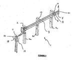
- Figures 1 a and 1b:
- are perspective views from the impact side of one embodiment of a guardrail according to the present invention; and
- Figures 2a and 2b:
- are reverse perspective views of the guardrail of
Figures 1a and 1b . - Figure 3:
- is an alternative embodiment of the guardrail of
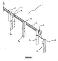
Figure 1a . - Figure 4:
- is an alternative embodiment of the guardrail of
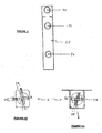
Figure 2a . - Figure 5:
- is a front elevational view of one embodiment of a cable routing means according to the present invention; and
- Figure 6a:
- Is a plan view of the cable routing means of
Figure 5 when in a first non-cable gripping orientation; - Figure 6b:
- is a plan view illustrating the rotation through which the cable routing means of
Figure 6a moves to a second cable gripping orientation; - Figure 7:
- is a front elevational view of an embodiment of a frangible fastener according to the present invention;
- Figure 8a:
- is a front elevational view of a frangible post in accordance within the present invention;
- Figure 8b:
- is a plan view of the frangible post of
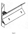
Figure 8a ; - Figure 9:
- is a perspective view of an impact slider according to a preferred embodiment of the invention; and
- Figure 10:
- shows an impact slider bracket (not attached to support posts) according to a preferred embodiment of the invention.
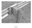
- Figure 11:
- is a view of a preferred impact slider assembly according to the invention as mounted to the support post.
- This invention is designed to be a substantially non-gating guardrail, meaning that at any point along the side of the guardrail from the terminal end onwards, an impacting vehicle on an angled collision may be substantially redirected away from its initial impact trajectory. It is also designed to substantially absorb energy during an end on impact to the terminal end.
- "Gating" is a term used within the guardrail industry to refer to sections of guardrail which are unable to withstand high impact side angle collisions, and significant guardrail deformation or ultimate failure or breakage may occur.
- For the purposes of this illustrative description,
Figures 1 a and 1 b will be referred together asFigure 1 ; similarlyFigures 2a and 2b will be referred to asFigure 2 . The guardrail 1 shown has been split into two sections for illustrative purposes only, and sections A and A' inFigures 1 a and 1b; and the same sections are labelled B and B' inFigures 2a and 2b should be joined to show an embodiment the guardrail according to the present invention. - In a first embodiment of the present invention, and with reference to
Figures 1 and2 there is provided a guardrail 1 with a cable routing orgripping means 2 at the terminal end. Thecable gripping means 2 may form part of an impact head (where an impact head is an additional guardrail bumper used to initially absorb some impact energy). - The cable gripping means 2 (and optionally impact head) may be bolted to the
first rail 3, at the other end of which is connected animpact slider device 4. Theimpact slider device 4 may facilitate the sliding of the first rail over each subsequent rail, thereby providing substantial telescoping ability to the guardrail, with each rail overlapping the next rail to enable this process during an end-on impact. The impact slider device may substantially surround the first rail and advantageously includes aportion 31 which gathers and retains telescoping railings during an impact. - The
rails spacer 17 or similar block type arrangement. - The
impact slider device 4 may also be used to detach or facilitate the disjointing or disconnection of a connection such asbolt 8 between arail 5 and asupport post 7. Preferably theimpact slider device 4 is a structural member of suitable strength that allows the bolts 8 (or similar connector) connectingrail 5 toposts 7a - 7g; orrail 5 torail 3 or thenext rail 6; to either be severed from the rail or pulled or bent free from the rail connection. Therails bolts 8 may be made of materials such as plastics or high density plastic or other composite materials, or frangible bolts, which are more likely to fail and be sheared off from the post connection (or from the rail to rail connection) by an impact from the slider, than a side angle impact with the guardrails. This may be an advantageous feature allowing the slider to operate and shear off post holdingrail bolts 8, whilst at the same time providing resistance to side angle impacts and reducing the likelihood of the guardrail gating. - In an alternative to plastic or weaker material bolts, a
fastener 8 composed of high strength materials or even a "standard" mild steel bolt could be structurally altered to provide frangible characteristics. For example, an alternativefrangible fastener 8 is shown inFigure 7 . The frangible bolt includes ahead portion 18, atail portion 19 with ashank portion 20 therebetween. The head portion has a minimumcross-sectional diameter 21 greater than the maximum cross-sectional diameter of the tail portion, and the shank portion includes afrangible zone 22 having a minimum cross-sectional diameter smaller than the tail portion's maximumcross-sectional diameter 23. - Advantageously, the frangible zone can be formed by the convergence of a tapered reduction in the cross-sectional diameter of the shank portion, with the frangible zone being located in the shank portion.
- In addition, the frangible fastener may structurally fail substantially at the frangible zone upon a force loading in shear direction X, to the frangible fastener's axial direction, that is, at an orthogonal direction to the fastener's longitudinal or axial direction.
- Ideally, the frangible fastener is a bolt, screw or similar threaded securing means. Such a securing means can be used to connect the guardrail rails to the support posts, and may be especially suitable for use with the guardrail slider device. For instance, the slider can impact the frangible fastener holding the rails onto the support posts, the fastener will be subjected to a shear force or impacting force, and as a consequence of the weakened fastener shank portion, the fastener can break (or structurally fail). Whereas, an impact with the fastener in a direction in-line with the longitudinal axis, that is in direction Y, of the fastener is less likely to induce fastener failure, as the impacting force is transferred down the length of the fastener and is not exposed to any regions of frangibility or weakness.
- For example, the frangible bolt as illustrated in
Figure 7 should preferably have a 6mm shank length, 16mm tail cross-sectional diameter, and an 8.5mm cross-sectional diameter at the narrowest section of the frangible zone. - A
cable 15 has anend 10 which may be attached to a soil anchor assembly or fixed such as at 11, at the terminal end of the guardrail. The other cable end 11a extends to a second anchor or fixed point 12, which may be a further soil anchor assembly, or alternatively, may be an anchoring assembly attached to a non-frangible support post or non-telescoping rail. Thecable 15 may be anchored bycable brackets 13 to the posts or rails or by any suitable cable anchoring system, such as bolts and welds or the like. The soil anchor assembly arrangement may include a sunken post (or I-beam) with flares orwinged portions 18 extending outwards from the post to engage with greater soil area and providing increased resistance to movement of the anchor assembly as a result of an impact with the guardrail. - The embodiment shown in
Figures 1 and2 of a guardrail system consists of asoil anchoring system 11 at the terminal end of the guardrail and provides a means to attach twocables cable gripping means 2, which may be a steel plate bolted to the terminal end of a length of rail 3 (orfirst post 7a). At the junction of the first 3 and second 5 rails (or sections of rails), there is an impact slider device or "slider" 4 that fits over the end of thefirst rail 3 and into which thenext rail 5 may slide. - The
cables cable gripping means 2, are positioned in a hollow orrecess 14 of the back side of the length of the rail (for example, the rail may be a W-shaped beam). The cables may extend until a point 11a where they may be anchored to the rail (or post, or other anchoring means) at a post downstream of thecable gripping means 2 using one ormore cable brackets 13 or other connecting and/or cable fixing means. Such means may be screw bolts, welded joints or other suitable devices enabling substantially secure cable anchoring. The cable may be tensioned, although this is not essential for the present invention to operate. - An alternative embodiment of the impact head is shown in
Figure 4 . The impact head 24 includes: at least one cable routing means through which a cable is threaded in a tortuous path and which thereby provides resistance to cable movement therethrough. Ideally, the path of the cable through the cable routing means includes at least one substantially 180° turn, or is in a substantially S or Z-shape. - Advantageously, during a collision, or impact, with the impact head 24, the at least one cable is forced through the
cable gripping means 2, where resistance to cable movement substantially facilitates impact energy dissipation. - The cable routing means may be a
planar bar member 25 adapted to receive and allow at least one cable to pass therethrough via at least three cable entry ports in series which are formed therein, forming the tortuous path which provides resistance to cable movement therethrough, such as is illustrated inFigures 1 a and 2a. - Alternatively, in an alternative embodiment of the impact head as illustrated in
Figures 3 ,4 ,5, 6a and 6b abar member 25 can be provided with a cable entry port or ports P1, P2 adapted to receive and allow at least one cable to pass directly therethrough, when said bar member is in a first non-cable-grippingorientation 26. Subsequently, upon rotation of the bar member about its longitudinal axis (substantially perpendicular to the cables length) through at least 90°, a second cable-grippingorientation 27 is reached. Advantageously, the bar member may be secured in the second orientation by locking means (not shown), such as by bolts or screws. The rotation of thebar member 25 from said first orientation to the second orientation ensures that the at least one cable follows a tortuous pathway. The rotation of thebar member 25 may be undertaken, for example by a crow bar inserted into a slot, S1, and then an angular or rotational force applied. - In use, energy from a head on impact with the impact head/
cable gripping means 2 is initially substantially absorbed by support post (7a), which may subsequently fail, preferably substantially at or near ground level 16. For example thefirst support post 7a would normally be impacted at or by the impact head/cable gripping means, and absorb energy before preferably failing (that is, being broken). Should a support post fail and be broken off at a height substantially above ground level than that would contact the impacting vehicle and then the vehicle may collide with the broken post and result in more severe impact energy absorption (possibly resulting in vehicle occupant damage due to sudden movement arrest). - Similarly, as the
slider device 4, impact head/cable gripping means 2 and first rail 3 (and subsequent rails) telescope down thesecond rail 5,rail 3 uponrail 5, each support post is impacted by theslider device 4 and preferably causes breakaway of the posts. Alternatively, a guardrail may also be provided in which just an impact slider is connected to the rails, and no cable gripping means or impact head is attached. - Preferably, the guardrail system employs energy absorption/dissipation systems which substantially control an impacting object momentum and directional motion. For example, energy may be absorbed or dissipated by the friction between the
cable 15 andcable gripping means 2. When the guardrail is impacted end on (that is, in the substantially longitudinal direction of the guardrail and impacting the impact head and/or cable gripping means initially), the whole ofrail 3, the impact head/cable gripping means 2 and theimpact slider device 4 move back in a telescoping manner overrail 5 and then subsequent downstream rails, such asrail 5 and/orrail 6. Energy is also absorbed by the friction of thecables 15 running through thecable gripping means 2, wherein the threaded cable configuration through the cable routing means follows the tortuous pathway. - Preferably, as the
cable gripping means 2 is attached to or forms an integral part of a bumper or impact head, as the impact head and cable gripping means move (as a result of an end-on impact with the impact head/guardrail), away from thecable anchor point 11, the cable gripping means is effectively forced to move along the cable(s), whilst the cable(s) 15, 15a remain substantially stationary as a result of being fixed at each of their ends. In doing so, the cable is forced through a number of bending movements created by the threading configuration in the cable gripping means. Preferably, the cable used has substantial resistance to flexing (such as steel cable), and energy is dissipated from the impact and imparted to energy used to bend the cable. - Additionally, as the
cable gripping means 2 moves along the cable(s) 15 and 15a, the cable is forced to run in surface-to-surface contact with the cable gripping means, which preferably results in additional frictional energy dissipation. In an even further alternative embodiment, thecable gripping means 2 may be in the form of a sleeve fitted around thecable - In an even further preferred energy dissipation system, the friction created by the impact slider device 4 (and rails 3, 5, 6) moving over one another during an impact event may help to absorb energy.
- Energy from a side angle impact with the guardrail 1 is absorbed by the flexion and/or deformation (whether by elastic or plastic deformation) of the rails, as well as by the tensile forces created in the cable(s) 15, 15a (which may help the rails to resist flexion and/or deformation).
- Preferably, the impacting object is redirected away from the guardrail 1 and the forces generated by the impact are distributed throughout the rails and cables either by deformation or tension generated in the cables and subsequently redirected to the cable fixing point.
- Preferably, a number of
support posts 7a-7g may be frangible or of a predetermined failure load which fail or substantially deform, consequently absorbing further impact energy. - Preferably an object, such as a vehicle, involved in a side angle impact is substantially redirected away from the guardrail, and back onto the road, and the guardrail itself is restrained from "gating" by the further tension created in the cables by the impacts induced lateral cable movement.
- In particular, a frangible post construction as illustrated in
Figure 8 may be especially suitable for re-directing an errant side-impacting vehicle back onto the road. The frangible post has afirst member 28 connected substantially orthogonally to asecond member 29. The first member is provided with at least one region ofweakness 30. Advantageously, this configuration allows a substantially frangible or weakened region to exist in the first member which may be more likely to be structurally affected during an impact, for example in direction T. In contrast, an impact in line with the second member will require a greater impact force to structurally affect the second member or post, for example in direction U. - In other words, because the first member is weakened in relation to an impact in a first direction and the second member has effectively no structural resistance to a force in that direction, the post will tend to bend or break at the weakened region when subjected to that force. In contrast, when impacted by a force substantially perpendicular to the first direction, the region of weakness in the first member has little effect on the frangibility of the post and the second member offers substantial resistance to deflection in that direction.
- The first and second members need not be attached to one another at exactly 90°, however this orientation may be most suitable for use with a guardrail where impacts are generally received either in-line with the longitudinal axis of the guardrail, or substantially perpendicular to the guardrail.
- The frangible post is designed to more easily structurally fail in an impact from a direction substantially in line with the longitudinal axis of the guardrail than in an impact substantially perpendicular to the guardrail.
- The at least one region of weakness can be formed by a cut-away
section 30 from the first member, or other similar notches or portions of the first member being removed. The frangible post formed may be selected from the following configurations: an I-beam, an L-beam, an X-beam, a T-beam, a Z-beam. The configuration chosen may depend on the post geometry required by a user. The first and second members are preferably integrally formed or welded together. - Ideally, each post is sunk into the ground, with the at least one region of weakness being at or near to ground level; which allows the post to break off at or near ground level during a post failure impact.
- For example, an I-beam configuration of the post as illustrated in
Figure 8b , should be aligned so that the first members are parallel with the road (and therefore guardrail). Each edge of the first member having a 12mm deep triangular notch removed from the first member, the first member of which has dimensions (excluding length) is about 100mm in width, and of about 20mm thickness. Such notches should preferably be made so that they are approximately 50mm below ground level (after the post has been "sunk"). - During an impact in an axial direction to the guardrail, a tear in the first member starts in the upstream note from the impact, while the downstream notch allows the first member to collapse and/or fail.
- Preferably, the guardrail as described above may be utilised in applications where protective barriers are required to separate vehicle traffic flow from each other, or safety to pedestrians from vehicles, or even to protect vehicles running off roads. It is desirable that the guardrail as described provides a non-gating design and which re-directs an errant vehicle from its correct path back onto a road or at least away from pedestrians on a footpath.
- The guardrail as described goes at least some way toward facilitating a system for controllably slowing a vehicle during an end-on barrier impact, as well as some way towards preventing the guardrail from gating during a side angled impact. It is also preferable that the "length of need" is substantially reduced compared to various existing technologies, and may most preferably have a length of need of almost zero distance.
- The guardrail as described may be utilised to form a part of whole of a guardrail system, although this system in particular may be applied to the terminal ends of a required guardrail or barrier or be substantially retrofit-able to existing guardrails.
-
Figure 10 shows an impact slider which includes means for attachment to a first rail in the form of a slider (33) which substantially conforms with the rail profile and with integral means for attachment to said first rail in the form of slotted holes (34) through which, in one preferred embodiment, fasteners may be passed and secured to said first rail. In use the angle bar shown (32) infigure 9 may butt up against one end of the impact slider so as to hold the first rail (not shown infigures 9 and10 but shown infigure 11 ) within the impact slider, thereby providing support via the support post and spacer (if present). - The impact slider bracket (30) also has means for attachment (31) via fasteners to the second rail, although this is a preferred embodiment and, in other embodiments, the impact slider bracket may be attached only to the second rail, or to both the first and second rail.
- In use and upon impact the impact slider may cause the impact slider bracket to come free of the support post by breaking the frangible fastening of the impact slider bracket to the support post (whether via a spacer or not). In end on impacts, as the impact slider bracket (33) still surrounds both the first and second rail it may gather telescoping rails approaching from the left hand side in
figure 11 whilst maintaining or at least substantially maintaining the rails in a "non-gating" configuration, that is, that the first rail (that shown on the left hand side offigure 11 ) may move substantially along the length of rail to (shown on the right infigure 11 ) so that a vehicle approaching from the traffic side of the rail (the top left hand corner as viewed infigure 11 ) has a low probability of penetrating through to the protected side (the bottom right corner as shown infigure 11 ) and thereby preventing "gating" of the rails. - The L shaped angle bracket (32) is attached to the impact slider bracket (30) and upon side impacts on the rails, prevents the joint between rails one and two from separating. This is achieved by the L shaped angle bracket (32) being larger than the slider (33) and therefore being unable to pass through the slider (33).
- Alternative embodiments include:
- A. An impact head for a guardrail including cable routing means configured to form a tortuous path through which a cable can be threaded.
- B. An impact head for a guardrail according to embodiment A wherein the cable routing means includes a member having two or more cable entry ports through which a cable may be threaded.
- C. An impact head for a guardrail according to embodiment A or embodiment B which includes one or more cables threaded through the cable routing means.
- D. An impact head for a guardrail according to Embodiment C wherein the cable routing means is configured so that when a force is applied to the impact head the cables are forced through the cable routing means, such that resistance to cable movement provided by the tortuous cable path limits movement of the impact head caused by the force.
- E. An impact head for a guardrail according to embodiment C or embodiment D wherein the cables are under tension.
- F. An impact head for a guardrail according to any one of embodiments C, D and E wherein at least one end of the cables is anchored to the ground.
- G. An impact head for a guardrail according to embodiment F wherein one end of the cables is anchored to the ground and the remaining end of the cables is anchored to a rail and/or a support post.
- H. An impact head for a guardrail according to embodiment G wherein the impact head is positioned substantially between the two anchor points
- I. A guardrail including:
- a plurality of support posts,
- a plurality of rails slidably interconnected and mounted directly or indirectly to the posts,
- at least one cable provided along at least a part of the length of the slidably interconnected rails wherein at least one end of the cables is fixed in relation to the ground,
- J. A guardrail according to embodiment I wherein both ends of the cables are fixed in relation to the ground.
- K. A guardrail according to embodiment I or embodiment J wherein the end of the cables located farthest from the cable routing means is anchored to a rail and/or a support post.
- L. A guardrail including:
- a plurality of support posts,
- a plurality of rails slidably interconnected and mounted directly or indirectly to the posts,
- at least one cable provided along at least a part of the length of said slidably interconnected rails wherein each end of the cables is fixed in relation to the ground, and
- an impact slider means substantially surrounding a first rail and including a portion which gathers and retains rails during an impact.
- M. A guardrail according to claim L additionally including an impact head according to any one of embodiments A to H.
- N. A guardrail according to embodiment L or embodiment M wherein the cable routing means is mounted on a first post and the impact slider device is attached to the end of a first rail.
- O. A guardrail according to embodiment N wherein the impact slider device is adapted so as to be able to slide along a second rail overlapping the end of the first rail.
- P. A frangible fastener for use in a guardrail or an impact head for a guardrail according to any one of the preceding claims wherein the frangible fastener includes:
- a head portion, a tail portion and a shank portion,
wherein the shank portion includes a frangible zone, having a minimum cross-sectional diameter smaller than the tail portion's maximum cross-sectional diameter. - Q. An impact head according to any one of embodiments A to H which includes one or more frangible fasteners according to embodiment P.
- R. A guardrail according to any one of embodiments I to O which includes one or more frangible fasteners according to embodiment P.
- S. A guardrail according to any one of embodiments I to O and R wherein it includes one or more frangible posts comprising:
- a first member substantially orthogonally connected to a second member,
- T. A method of constructing a guardrail including the steps of:
- installing a plurality of support posts,
- slidably interconnecting a plurality of rails and mounting them directly or indirectly to said posts,
- fixing at least one end of at least one cable to the ground, and
- positioning an impact head according to any one of embodiments A to H and Q at one end of the slidably interconnected rails and threading at least one cable through it.
- U. An impact head according to embodiment A substantially as herein described with reference to any one of the accompanying drawings thereof.
- V. An impact head according to any one of embodiments A to H and Q substantially as herein described.
- W. A guardrail according to embodiment I or embodiment L substantially as herein described with reference to any one of the accompanying drawings thereof.
- X. A guardrail according to any one of embodiments I to O, R and S substantially as herein described.
- Y. A frangible fastener according to embodiment P substantially as herein described with reference to any one of the accompanying drawings thereof.
- Z. A frangible fastener according to embodiment P substantially as herein described.
- AA A method according to embodiment T substantially as herein described with reference to any one of the accompanying drawings thereof.
- AB. A method according to embodiment T substantially as herein described.
- Aspects of the present invention have been described by way of example only and it should be appreciated that modifications and additions may be made thereto without departing from the scope of the appended claims.
wherein the shank portion includes a frangible zone, having a minimum cross-sectional diameter smaller than the tail portion's maximum cross-sectional diameter.
Claims (12)
- An impact slider assembly for a guardrail which includes:a slider mechanism attached to a first rail and second rail which substantially conforms with the rail profile; andan integral means for attachment to the first rail,characterised in that the slider mechanism gathers telescoping rails whilst substantially maintaining the strength of the rails in a fully re-directing manner.
- An impact slider assembly for a guardrail as claimed in claim 1 wherein slider mechanism includes at least one fastener which passes through and secures the first rail.
- An impact slider assembly for a guardrail as claimed in any one of the proceeding claims wherein the impact slider assembly includes a slider bracket.
- An impact slider assembly for a guardrail as claimed in any one of the proceeding claims wherein the impact slider assembly includes an angled bar which abuts against at least one edge of the slider bracket.
- An impact slider assembly for a guardrail as claimed in claim 4 wherein the angled bar is larger than the impact slider to prevent the angled bar to pass through the impact slider.
- An impact slider assembly for a guardrail as claimed in claim 5 wherein the angled bar is fastened to the slider bracket.
- An impact slider assembly for a guardrail as claimed in any one of claims 5 or 6 wherein the angled bar is substantially L-shaped.
- An impact slider as claimed in any one of claims 4 to 7 wherein the angled bar and impact slider bracket upon impact of the rails, prevents the joint between the rails from separating.
- An impact slider assembly for a guardrail as claimed in any one of claims 4 to 8 wherein the impact slider bracket includes and is attached to at least the second rail.
- An impact slider assembly for a guardrail as claimed in any one of claims 4 to 9 in a guardrail assembly which when in use, gathers the telescoping rails whilst maintaining or at least substantially maintaining the strength of the rails in a fully re-directing manner.
- An impact slider assembly for a guardrail substantially as hereinbefore described and as illustrated with reference to Figures 9 to 11.
- A guardrail including an impact slider assembly as claimed in any one of the preceding claims.
Applications Claiming Priority (3)
| Application Number | Priority Date | Filing Date | Title |
|---|---|---|---|
| NZ528396A NZ528396A (en) | 2003-09-22 | 2003-09-22 | Guardrail |
| NZ53482604 | 2004-08-20 | ||
| EP04775152.4A EP1678379B1 (en) | 2003-09-22 | 2004-09-22 | Guardrail |
Related Parent Applications (3)
| Application Number | Title | Priority Date | Filing Date |
|---|---|---|---|
| EP04775152.4 Division | 2004-09-22 | ||
| EP04775152.4A Division EP1678379B1 (en) | 2003-09-22 | 2004-09-22 | Guardrail |
| EP04775152.4A Division-Into EP1678379B1 (en) | 2003-09-22 | 2004-09-22 | Guardrail |
Publications (3)
| Publication Number | Publication Date |
|---|---|
| EP2025817A2 true EP2025817A2 (en) | 2009-02-18 |
| EP2025817A3 EP2025817A3 (en) | 2011-11-30 |
| EP2025817B1 EP2025817B1 (en) | 2018-06-13 |
Family
ID=34380513
Family Applications (3)
| Application Number | Title | Priority Date | Filing Date |
|---|---|---|---|
| EP04775152.4A Active EP1678379B1 (en) | 2003-09-22 | 2004-09-22 | Guardrail |
| EP08019591.0A Active EP2025817B1 (en) | 2003-09-22 | 2004-09-22 | Guardrail |
| EP08014197.1A Active EP2006451B1 (en) | 2003-09-22 | 2004-09-22 | Guardrail |
Family Applications Before (1)
| Application Number | Title | Priority Date | Filing Date |
|---|---|---|---|
| EP04775152.4A Active EP1678379B1 (en) | 2003-09-22 | 2004-09-22 | Guardrail |
Family Applications After (1)
| Application Number | Title | Priority Date | Filing Date |
|---|---|---|---|
| EP08014197.1A Active EP2006451B1 (en) | 2003-09-22 | 2004-09-22 | Guardrail |
Country Status (7)
| Country | Link |
|---|---|
| US (3) | US7699293B2 (en) |
| EP (3) | EP1678379B1 (en) |
| AU (3) | AU2004274835B2 (en) |
| CA (2) | CA2634710C (en) |
| ES (3) | ES2581977T3 (en) |
| WO (1) | WO2005028757A1 (en) |
| ZA (1) | ZA200700520B (en) |
Families Citing this family (39)
| Publication number | Priority date | Publication date | Assignee | Title |
|---|---|---|---|---|
| US20040140460A1 (en) | 2001-08-29 | 2004-07-22 | Heimbecker Chad Garrett | Integrated cable guardrail system |
| AU2004274835B2 (en) * | 2003-09-22 | 2010-09-16 | Australian Construction Products Pty Limited | Guardrail |
| US20080083914A1 (en) * | 2004-07-19 | 2008-04-10 | Ochoa Carlos M | Posts and release mechanism for highway safety structures |
| US7249908B2 (en) | 2004-10-28 | 2007-07-31 | Trinity Industries, Inc. | Combined guardrail and cable safety systems |
| NZ546970A (en) | 2006-05-04 | 2009-01-31 | Armorflex Ltd | Improvements in and relating to cable-barriers |
| US8596617B2 (en) | 2006-11-06 | 2013-12-03 | Axip Limited | Impact energy dissipation system |
| NZ555598A (en) | 2007-06-01 | 2010-02-26 | Armorflex Ltd | Improved Barrier Section Connection System |
| NZ556782A (en) | 2007-07-27 | 2010-03-26 | Armorflex Ltd | Method of producing a frangible post |
| ES1068049Y (en) * | 2008-05-28 | 2008-11-01 | Hierros Y Aplanaciones S A Hia | FUSE MECHANISM FOR THE SCREWED UNION BETWEEN THE HORIZONTAL FENCE AND THE VERTICAL SUPPORT POST OF METAL SAFETY BARRIERS FOR VEHICLE CONTAINMENT, FOR USE IN MARGINS AND MEDIUM ROADS |
| US8424849B2 (en) * | 2008-06-04 | 2013-04-23 | Axip Limited | Guardrail |
| US8215619B2 (en) | 2009-03-31 | 2012-07-10 | Energy Absorption Systems, Inc. | Guardrail assembly, breakaway support post for a guardrail and methods for the assembly and use thereof |
| US20110095251A1 (en) * | 2009-10-27 | 2011-04-28 | Barrier Systems, Inc. | Vehicle crash attenuator apparatus |
| US8491216B2 (en) | 2009-10-27 | 2013-07-23 | Lindsay Transportation Solutions, Inc. | Vehicle crash attenuator apparatus |
| US8235359B2 (en) | 2009-10-27 | 2012-08-07 | Barrier Systems, Inc. | Vehicle crash attenuator apparatus |
| US8910455B2 (en) | 2010-03-19 | 2014-12-16 | Weihong Yang | Composite I-beam member |
| US8820033B2 (en) | 2010-03-19 | 2014-09-02 | Weihong Yang | Steel and wood composite structure with metal jacket wood studs and rods |
| AU2011205073B2 (en) | 2010-08-12 | 2015-02-12 | Valmont Highway Technology Limited | Improvements in and Relating to Barriers |
| CN102753758A (en) * | 2010-12-10 | 2012-10-24 | 百瑞系统公司 | Vehicle crash attenuator apparatus |
| WO2012106301A1 (en) | 2011-02-01 | 2012-08-09 | Energy Absorption Systems, Inc. | End terminal |
| NZ590876A (en) * | 2011-12-23 | 2012-09-28 | Axip Ltd | A coupling arrangment for guardrails which upon telescopic slinding of the rails causes an increasing clamping force between them |
| NZ591857A (en) | 2011-03-22 | 2013-09-27 | Axip Ltd | Energy Absorbing Apparatus |
| MY168835A (en) | 2011-05-30 | 2018-12-04 | Ind Galvanizers Corp Pty Ltd | Improved barrier construction |
| AU2015201385B2 (en) * | 2011-05-30 | 2017-11-23 | Industrial Galvanizers Corporation Pty Ltd | Improved Barrier Construction |
| GB2499368A (en) * | 2012-01-13 | 2013-08-21 | Zaun Ltd | A temporary barrier assembly with barrier members and arrestor |
| WO2014066350A2 (en) | 2012-10-24 | 2014-05-01 | Energy Absorption Systems, Inc. | Frangible post for highway barrier end terminals |
| US9200417B2 (en) * | 2012-11-27 | 2015-12-01 | Energy Absorption Systems, Inc. | Guardrail system with a releasable post |
| KR101356566B1 (en) * | 2013-01-17 | 2014-01-29 | 주식회사 케이씨이엔지니어링 | Flexible barrier improved impact energy absorbing capacity |
| US10036132B2 (en) | 2013-08-26 | 2018-07-31 | Dean L. Sicking | Twist box guardrail terminal |
| EP3154644A1 (en) | 2014-06-10 | 2017-04-19 | Gamba, Davide | Sliding rope safety device for roofs and the like, corresponding method for damping the stresses acting on a user of a rope safety device and guard rail with a sliding rope |
| ITUB20154764A1 (en) | 2015-10-27 | 2017-04-27 | Davide Gamba | NEW SECURITY DEVICE WITH SLIDING CABLE FOR PRESSURED PIPELINES OR SIMILAR SYSTEMS OR EQUIPMENT |
| US9611599B1 (en) | 2015-12-03 | 2017-04-04 | Lindsay Transportation Solutions, Inc. | Guardrail crash absorbing assembly |
| US9611601B1 (en) | 2015-12-17 | 2017-04-04 | Lindsay Transportation Solutions, Inc. | Crash absorbing guardrail panel assembly |
| US10378165B2 (en) | 2017-01-31 | 2019-08-13 | Lindsay Transportation Solutions, Inc. | Guardrail crash absorbing assembly |
| US10501901B2 (en) | 2017-02-23 | 2019-12-10 | Lindsay Transportation Solutions, Inc. | Guardrail crash absorbing assembly |
| JP6321277B1 (en) * | 2017-09-05 | 2018-05-09 | 国立研究開発法人土木研究所 | Flexible column for road protection fence |
| AU2019206002A1 (en) | 2018-07-26 | 2020-02-13 | Industrial Galvanizers Corporation Pty Ltd | Improved Spacer Piece for a Guard Rail System |
| USD891963S1 (en) * | 2018-09-19 | 2020-08-04 | Highway Care Ltd. | Combined T-barrier connector and barrier |
| GB2588223B (en) | 2019-10-17 | 2023-11-15 | Hill & Smith Ltd | Beam Connection device |
| CN113005953B (en) * | 2021-03-08 | 2022-09-09 | 浙江康诚建设集团有限公司 | Protective fence mounting mechanism for municipal engineering and operation method thereof |
Family Cites Families (56)
| Publication number | Priority date | Publication date | Assignee | Title |
|---|---|---|---|---|
| US1722994A (en) | 1927-05-05 | 1929-08-06 | American Cable Co Inc | Hitch for wire rope |
| US1950965A (en) * | 1932-04-08 | 1934-03-13 | Blackburn Jasper | Rail guard |
| US3350039A (en) * | 1965-10-18 | 1967-10-31 | Wilbur D Crater | Clutching means for launching and arresting aircraft and the like |
| US3617076A (en) | 1967-10-27 | 1971-11-02 | Unistrut Corp | Fastening clamp |
| SE344314B (en) * | 1969-11-14 | 1972-04-10 | Borgs Fabriks Ab | |
| US3776520A (en) * | 1972-11-06 | 1973-12-04 | J P C Inc | Energy absorbing highway guardrail |
| US3912404A (en) * | 1975-01-02 | 1975-10-14 | Herbert L Katt | Highway post construction |
| IT1031675B (en) * | 1975-02-12 | 1979-05-10 | Snam Progetti | DEVICE FOR THE ABSORPTION OF IMPACT ENERGY |
| US3982734A (en) | 1975-06-30 | 1976-09-28 | Dynamics Research And Manufacturing, Inc. | Impact barrier and restraint |
| US4222552A (en) * | 1978-10-20 | 1980-09-16 | Matteo Sr George W | Highway guardrail cover |
| US4330106A (en) | 1979-05-02 | 1982-05-18 | Chisholm Douglas B | Guard rail construction |
| US4452431A (en) | 1982-05-19 | 1984-06-05 | Energy Absorption Systems, Inc. | Restorable fender panel |
| US4674911A (en) | 1984-06-13 | 1987-06-23 | Energy Absorption Systems, Inc. | Energy absorbing pneumatic crash cushion |
| FR2576047B1 (en) * | 1985-01-14 | 1987-02-13 | Mecanroc | PROTECTIVE BARRIER AGAINST FALLING STONES WITH MOORING CABLES LIKELY TO SLIDE IN SHOCK ABSORBERS |
| US4655434A (en) * | 1986-04-24 | 1987-04-07 | Southwest Research Institute | Energy absorbing guardrail terminal |
| US4678166A (en) * | 1986-04-24 | 1987-07-07 | Southwest Research Institute | Eccentric loader guardrail terminal |
| US4739971A (en) | 1987-03-05 | 1988-04-26 | Ruane George W | Guard rail assembly |
| US4780020A (en) | 1987-08-07 | 1988-10-25 | Terio Charles J | Terrorist vehicle barrier |
| US4838523A (en) * | 1988-07-25 | 1989-06-13 | Syro Steel Company | Energy absorbing guard rail terminal |
| GB2224528B (en) * | 1988-11-08 | 1993-02-10 | British Ropes Ltd | Tensioned cable safety fence |
| US5022782A (en) * | 1989-11-20 | 1991-06-11 | Energy Absorption Systems, Inc. | Vehicle crash barrier |
| ES2053311T3 (en) * | 1990-12-31 | 1994-07-16 | Fatzer Ag | DEVICE FOR SHOCK ABSORBING FOR A CABLE REQUESTED TO TRACTION, IN CASE OF FALLING STONES AND SNOW ACCUMULATIONS. |
| US5118056A (en) | 1991-03-22 | 1992-06-02 | Jeanise Dorothy J | Barricade apparatus |
| US5391016A (en) * | 1992-08-11 | 1995-02-21 | The Texas A&M University System | Metal beam rail terminal |
| US5435524A (en) * | 1993-12-06 | 1995-07-25 | Ingram; L. Howard | Impact fence |
| US5435525A (en) * | 1994-07-28 | 1995-07-25 | Roy; Peter J. | Negative pressure chamber table for gas-driven cutting apparatus |
| FR2723603B1 (en) * | 1994-08-11 | 1996-10-18 | Autouroutes Du Sud De La Franc | SHOCK ATTENUATING DEVICE FOR PLACEMENT ON A ROAD NETWORK IN FRONT OF AN OBSTACLE, WITH A VIEW TO SLOWING DOWN A VEHICLE HAVING IT IN IT. |
| DK27795A (en) * | 1995-03-20 | 1996-09-21 | Gunnar Davidsen | Profile piece for cable car guard |
| AUPN408495A0 (en) * | 1995-07-10 | 1995-08-03 | Bhp Steel (Jla) Pty Limited | Breakaway post connector |
| US6065738A (en) * | 1996-11-29 | 2000-05-23 | Brifen Limited | Anchor for cables |
| US5775675A (en) * | 1997-04-02 | 1998-07-07 | Safety By Design, Inc. | Sequential kinking guardrail terminal system |
| US5851005A (en) * | 1997-04-15 | 1998-12-22 | Muller; Franz M. | Energy absorption apparatus |
| EP1365070B1 (en) * | 1997-05-09 | 2016-01-06 | Trinity Industries, Inc. | Breakaway support post for highway guardrail end treatments |
| US5967497A (en) | 1997-12-15 | 1999-10-19 | Energy Absorption Systems, Inc. | Highway barrier and guardrail |
| ES2215219T3 (en) * | 1997-12-22 | 2004-10-01 | Autostrada Del Brennero S.P.A. | SAFETY BARRIER FOR HIGHWAY PRETIL. |
| US6173943B1 (en) * | 1998-04-22 | 2001-01-16 | Energy Absorption Systems, Inc. | Guardrail with slidable impact-receiving element |
| US6149134A (en) | 1998-10-01 | 2000-11-21 | Wisconsin Alumni Research Foundation | Composite material highway guardrail having high impact energy dissipation characteristics |
| SE513130C2 (en) | 1998-11-27 | 2000-07-10 | Anders Welandsson | Method and apparatus for preventing damage when colliding with the end portion of a road rail |
| US6398192B1 (en) * | 1999-01-06 | 2002-06-04 | Trn Business Trust | Breakaway support post for highway guardrail end treatments |
| IT1307663B1 (en) * | 1999-02-03 | 2001-11-14 | Snoline Spa | IMPROVED STRUCTURE OF SAFETY ROAD BARRIER TERMINAL WITH GRADUAL ABSORPTION OF IMPACT ENERGY |
| US6290427B1 (en) | 1999-02-16 | 2001-09-18 | Carlos M. Ochoa | Guardrail beam with enhanced stability |
| US20040140460A1 (en) * | 2001-08-29 | 2004-07-22 | Heimbecker Chad Garrett | Integrated cable guardrail system |
| ITTO20011105A1 (en) * | 2001-11-27 | 2003-05-27 | C R F Societa Con Sortile Per | ,, RETRACTABLE ROAD BARRIER ,,. |
| WO2003064772A1 (en) * | 2002-01-30 | 2003-08-07 | The Texas A & M University System | Cable guardrail release system |
| US7785031B2 (en) | 2002-02-07 | 2010-08-31 | Universal Safety Response, Inc. | Energy absorbing system |
| US6962328B2 (en) | 2002-05-28 | 2005-11-08 | Trn Business Trust | Cable safety system |
| US6854716B2 (en) * | 2002-06-19 | 2005-02-15 | Trn Business Trust | Crash cushions and other energy absorbing devices |
| FR2846673A1 (en) * | 2002-11-06 | 2004-05-07 | Claude Alix Georges Pomero | Safety barrier for roadside has additional larger slide profile attached to existing mountings by bolting |
| US6962459B2 (en) | 2003-08-12 | 2005-11-08 | Sci Products Inc. | Crash attenuator with cable and cylinder arrangement for decelerating vehicles |
| AU2004274835B2 (en) | 2003-09-22 | 2010-09-16 | Australian Construction Products Pty Limited | Guardrail |
| FR2872834A1 (en) * | 2004-07-06 | 2006-01-13 | Profiles Du Ct Soc Par Actions | Guard rail`s movable string rail mounting device for traffic lane, has support assembly arranged for tilting movable string rail to contact guiding unit that permits rail to slide when rail is displaced linearly |
| PL1794372T3 (en) | 2004-09-15 | 2015-04-30 | Energy Absorption System | Crash cushion |
| US20060102883A1 (en) * | 2004-09-29 | 2006-05-18 | Creative Pultrusions, Inc. | Pultruded composite guardrail |
| US20070252124A1 (en) | 2006-04-27 | 2007-11-01 | Bryson Products Inc. | Guardrail System |
| DE102006038336B3 (en) * | 2006-08-15 | 2007-12-20 | Spig Schutzplanken-Produktions-Gesellschaft Mbh & Co. Kg | Protection plank arrangement for steel bridge construction, has C-shaped profile strands extending along center elevational area and upper end of anchoring profile, and protection plank strand extending before one of strands in area |
| US7445402B1 (en) | 2007-12-18 | 2008-11-04 | Chih-Hung Chen | Barrier plate for highways |
-
2004
- 2004-09-22 AU AU2004274835A patent/AU2004274835B2/en active Active
- 2004-09-22 EP EP04775152.4A patent/EP1678379B1/en active Active
- 2004-09-22 EP EP08019591.0A patent/EP2025817B1/en active Active
- 2004-09-22 CA CA2634710A patent/CA2634710C/en active Active
- 2004-09-22 ES ES04775152.4T patent/ES2581977T3/en active Active
- 2004-09-22 ES ES08019591.0T patent/ES2679122T3/en active Active
- 2004-09-22 WO PCT/NZ2004/000227 patent/WO2005028757A1/en active Application Filing
- 2004-09-22 US US10/572,722 patent/US7699293B2/en active Active
- 2004-09-22 EP EP08014197.1A patent/EP2006451B1/en active Active
- 2004-09-22 ES ES08014197T patent/ES2712149T3/en active Active
- 2004-09-22 CA CA2539617A patent/CA2539617C/en active Active
-
2007
- 2007-04-21 ZA ZA2007/00520A patent/ZA200700520B/en unknown
-
2008
- 2008-06-04 US US12/132,942 patent/US7926790B2/en active Active
- 2008-06-04 US US12/132,958 patent/US8177194B2/en active Active
- 2008-11-06 AU AU2008243129A patent/AU2008243129A1/en not_active Abandoned
-
2009
- 2009-04-14 AU AU2009201430A patent/AU2009201430B2/en active Active
Non-Patent Citations (1)
| Title |
|---|
| None |
Also Published As
| Publication number | Publication date |
|---|---|
| AU2004274835A1 (en) | 2005-03-31 |
| AU2008243129A1 (en) | 2008-11-27 |
| EP2025817B1 (en) | 2018-06-13 |
| EP2006451A2 (en) | 2008-12-24 |
| US8177194B2 (en) | 2012-05-15 |
| US20090065754A1 (en) | 2009-03-12 |
| US20080283808A1 (en) | 2008-11-20 |
| EP1678379A4 (en) | 2009-12-30 |
| EP2025817A3 (en) | 2011-11-30 |
| WO2005028757A1 (en) | 2005-03-31 |
| CA2634710C (en) | 2011-08-23 |
| US20070131918A1 (en) | 2007-06-14 |
| EP1678379B1 (en) | 2016-04-27 |
| ES2581977T3 (en) | 2016-09-08 |
| EP1678379A1 (en) | 2006-07-12 |
| CA2539617C (en) | 2012-06-05 |
| AU2004274835B2 (en) | 2010-09-16 |
| CA2634710A1 (en) | 2005-03-31 |
| US7699293B2 (en) | 2010-04-20 |
| EP2006451A3 (en) | 2011-11-30 |
| AU2009201430A1 (en) | 2009-05-07 |
| CA2539617A1 (en) | 2005-03-31 |
| EP2006451B1 (en) | 2019-01-23 |
| AU2004274835A2 (en) | 2008-05-08 |
| ES2712149T3 (en) | 2019-05-09 |
| ZA200700520B (en) | 2010-11-24 |
| AU2009201430B2 (en) | 2011-10-06 |
| US7926790B2 (en) | 2011-04-19 |
| ES2679122T3 (en) | 2018-08-22 |
Similar Documents
| Publication | Publication Date | Title |
|---|---|---|
| EP1678379B1 (en) | Guardrail | |
| US8424849B2 (en) | Guardrail | |
| US8596617B2 (en) | Impact energy dissipation system | |
| EP2494111B1 (en) | Vehicle crash attenuator apparatus | |
| US8491216B2 (en) | Vehicle crash attenuator apparatus | |
| NZ528396A (en) | Guardrail | |
| AU2015258343A1 (en) | Impact slider assembly for guardrail | |
| NZ548116A (en) | Guardrail impact slider which gathers telescoping rails whilst maintaining strength of rails in a re-directing manner | |
| AU2008201512A1 (en) | Guardrail | |
| AU2015258340A1 (en) | Guardrail | |
| NZ539397A (en) | Guardrail with impact slider assembly with first and second rails being gathered and retained via telescopic overlap | |
| AU2012201477A1 (en) | Impact slider assembly for guardrail | |
| AU2012201479A1 (en) | Guardrail | |
| ZA200603206B (en) | Guardrail | |
| NZ544397A (en) | Guardrail | |
| US20110095251A1 (en) | Vehicle crash attenuator apparatus |
Legal Events
| Date | Code | Title | Description |
|---|---|---|---|
| PUAI | Public reference made under article 153(3) epc to a published international application that has entered the european phase |
Free format text: ORIGINAL CODE: 0009012 |
|
| AC | Divisional application: reference to earlier application |
Ref document number: 1678379 Country of ref document: EP Kind code of ref document: P |
|
| AK | Designated contracting states |
Kind code of ref document: A2 Designated state(s): AT BE BG CH CY CZ DE DK EE ES FI FR GB GR HU IE IT LI LU MC NL PL PT RO SE SI SK TR |
|
| REG | Reference to a national code |
Ref country code: HK Ref legal event code: DE Ref document number: 1125426 Country of ref document: HK |
|
| RAP1 | Party data changed (applicant data changed or rights of an application transferred) |
Owner name: AXIP LIMITED |
|
| REG | Reference to a national code |
Ref country code: DE Ref legal event code: R079 Ref document number: 602004052831 Country of ref document: DE Free format text: PREVIOUS MAIN CLASS: E01F0015140000 Ipc: E01F0015020000 |
|
| PUAL | Search report despatched |
Free format text: ORIGINAL CODE: 0009013 |
|
| AK | Designated contracting states |
Kind code of ref document: A3 Designated state(s): AT BE BG CH CY CZ DE DK EE ES FI FR GB GR HU IE IT LI LU MC NL PL PT RO SE SI SK TR |
|
| RIC1 | Information provided on ipc code assigned before grant |
Ipc: E01F 15/04 20060101ALI20111025BHEP Ipc: E01F 15/02 20060101AFI20111025BHEP |
|
| 17P | Request for examination filed |
Effective date: 20120528 |
|
| AKX | Designation fees paid |
Designated state(s): AT BE BG CH CY CZ DE DK EE ES FI FR GB GR HU IE IT LI LU MC NL PL PT RO SE SI SK TR |
|
| 17Q | First examination report despatched |
Effective date: 20130808 |
|
| RAP1 | Party data changed (applicant data changed or rights of an application transferred) |
Owner name: AXIP LIMITED |
|
| RAP1 | Party data changed (applicant data changed or rights of an application transferred) |
Owner name: VALMONT HIGHWAY TECHNOLOGY LIMITED |
|
| STAA | Information on the status of an ep patent application or granted ep patent |
Free format text: STATUS: EXAMINATION IS IN PROGRESS |
|
| GRAP | Despatch of communication of intention to grant a patent |
Free format text: ORIGINAL CODE: EPIDOSNIGR1 |
|
| STAA | Information on the status of an ep patent application or granted ep patent |
Free format text: STATUS: GRANT OF PATENT IS INTENDED |
|
| INTG | Intention to grant announced |
Effective date: 20180103 |
|
| GRAS | Grant fee paid |
Free format text: ORIGINAL CODE: EPIDOSNIGR3 |
|
| GRAA | (expected) grant |
Free format text: ORIGINAL CODE: 0009210 |
|
| STAA | Information on the status of an ep patent application or granted ep patent |
Free format text: STATUS: THE PATENT HAS BEEN GRANTED |
|
| AC | Divisional application: reference to earlier application |
Ref document number: 1678379 Country of ref document: EP Kind code of ref document: P |
|
| AK | Designated contracting states |
Kind code of ref document: B1 Designated state(s): AT BE BG CH CY CZ DE DK EE ES FI FR GB GR HU IE IT LI LU MC NL PL PT RO SE SI SK TR |
|
| REG | Reference to a national code |
Ref country code: GB Ref legal event code: FG4D |
|
| REG | Reference to a national code |
Ref country code: CH Ref legal event code: EP Ref country code: AT Ref legal event code: REF Ref document number: 1008659 Country of ref document: AT Kind code of ref document: T Effective date: 20180615 |
|
| REG | Reference to a national code |
Ref country code: IE Ref legal event code: FG4D |
|
| REG | Reference to a national code |
Ref country code: DE Ref legal event code: R096 Ref document number: 602004052831 Country of ref document: DE |
|
| REG | Reference to a national code |
Ref country code: ES Ref legal event code: FG2A Ref document number: 2679122 Country of ref document: ES Kind code of ref document: T3 Effective date: 20180822 |
|
| REG | Reference to a national code |
Ref country code: FR Ref legal event code: PLFP Year of fee payment: 15 |
|
| REG | Reference to a national code |
Ref country code: NL Ref legal event code: MP Effective date: 20180613 |
|
| PG25 | Lapsed in a contracting state [announced via postgrant information from national office to epo] |
Ref country code: SE Free format text: LAPSE BECAUSE OF FAILURE TO SUBMIT A TRANSLATION OF THE DESCRIPTION OR TO PAY THE FEE WITHIN THE PRESCRIBED TIME-LIMIT Effective date: 20180613 Ref country code: FI Free format text: LAPSE BECAUSE OF FAILURE TO SUBMIT A TRANSLATION OF THE DESCRIPTION OR TO PAY THE FEE WITHIN THE PRESCRIBED TIME-LIMIT Effective date: 20180613 Ref country code: BG Free format text: LAPSE BECAUSE OF FAILURE TO SUBMIT A TRANSLATION OF THE DESCRIPTION OR TO PAY THE FEE WITHIN THE PRESCRIBED TIME-LIMIT Effective date: 20180913 Ref country code: CY Free format text: LAPSE BECAUSE OF FAILURE TO SUBMIT A TRANSLATION OF THE DESCRIPTION OR TO PAY THE FEE WITHIN THE PRESCRIBED TIME-LIMIT Effective date: 20180613 |
|
| PG25 | Lapsed in a contracting state [announced via postgrant information from national office to epo] |
Ref country code: GR Free format text: LAPSE BECAUSE OF FAILURE TO SUBMIT A TRANSLATION OF THE DESCRIPTION OR TO PAY THE FEE WITHIN THE PRESCRIBED TIME-LIMIT Effective date: 20180914 |
|
| REG | Reference to a national code |
Ref country code: AT Ref legal event code: MK05 Ref document number: 1008659 Country of ref document: AT Kind code of ref document: T Effective date: 20180613 |
|
| REG | Reference to a national code |
Ref country code: HK Ref legal event code: GR Ref document number: 1125426 Country of ref document: HK |
|
| PG25 | Lapsed in a contracting state [announced via postgrant information from national office to epo] |
Ref country code: NL Free format text: LAPSE BECAUSE OF FAILURE TO SUBMIT A TRANSLATION OF THE DESCRIPTION OR TO PAY THE FEE WITHIN THE PRESCRIBED TIME-LIMIT Effective date: 20180613 |
|
| PG25 | Lapsed in a contracting state [announced via postgrant information from national office to epo] |
Ref country code: SK Free format text: LAPSE BECAUSE OF FAILURE TO SUBMIT A TRANSLATION OF THE DESCRIPTION OR TO PAY THE FEE WITHIN THE PRESCRIBED TIME-LIMIT Effective date: 20180613 Ref country code: EE Free format text: LAPSE BECAUSE OF FAILURE TO SUBMIT A TRANSLATION OF THE DESCRIPTION OR TO PAY THE FEE WITHIN THE PRESCRIBED TIME-LIMIT Effective date: 20180613 Ref country code: AT Free format text: LAPSE BECAUSE OF FAILURE TO SUBMIT A TRANSLATION OF THE DESCRIPTION OR TO PAY THE FEE WITHIN THE PRESCRIBED TIME-LIMIT Effective date: 20180613 Ref country code: CZ Free format text: LAPSE BECAUSE OF FAILURE TO SUBMIT A TRANSLATION OF THE DESCRIPTION OR TO PAY THE FEE WITHIN THE PRESCRIBED TIME-LIMIT Effective date: 20180613 Ref country code: PL Free format text: LAPSE BECAUSE OF FAILURE TO SUBMIT A TRANSLATION OF THE DESCRIPTION OR TO PAY THE FEE WITHIN THE PRESCRIBED TIME-LIMIT Effective date: 20180613 Ref country code: RO Free format text: LAPSE BECAUSE OF FAILURE TO SUBMIT A TRANSLATION OF THE DESCRIPTION OR TO PAY THE FEE WITHIN THE PRESCRIBED TIME-LIMIT Effective date: 20180613 |
|
| REG | Reference to a national code |
Ref country code: DE Ref legal event code: R097 Ref document number: 602004052831 Country of ref document: DE |
|
| PLBE | No opposition filed within time limit |
Free format text: ORIGINAL CODE: 0009261 |
|
| STAA | Information on the status of an ep patent application or granted ep patent |
Free format text: STATUS: NO OPPOSITION FILED WITHIN TIME LIMIT |
|
| PG25 | Lapsed in a contracting state [announced via postgrant information from national office to epo] |
Ref country code: MC Free format text: LAPSE BECAUSE OF FAILURE TO SUBMIT A TRANSLATION OF THE DESCRIPTION OR TO PAY THE FEE WITHIN THE PRESCRIBED TIME-LIMIT Effective date: 20180613 |
|
| REG | Reference to a national code |
Ref country code: CH Ref legal event code: PL |
|
| 26N | No opposition filed |
Effective date: 20190314 |
|
| PG25 | Lapsed in a contracting state [announced via postgrant information from national office to epo] |
Ref country code: DK Free format text: LAPSE BECAUSE OF FAILURE TO SUBMIT A TRANSLATION OF THE DESCRIPTION OR TO PAY THE FEE WITHIN THE PRESCRIBED TIME-LIMIT Effective date: 20180613 Ref country code: SI Free format text: LAPSE BECAUSE OF FAILURE TO SUBMIT A TRANSLATION OF THE DESCRIPTION OR TO PAY THE FEE WITHIN THE PRESCRIBED TIME-LIMIT Effective date: 20180613 |
|
| REG | Reference to a national code |
Ref country code: BE Ref legal event code: MM Effective date: 20180930 |
|
| REG | Reference to a national code |
Ref country code: IE Ref legal event code: MM4A |
|
| PG25 | Lapsed in a contracting state [announced via postgrant information from national office to epo] |
Ref country code: LU Free format text: LAPSE BECAUSE OF NON-PAYMENT OF DUE FEES Effective date: 20180922 |
|
| PG25 | Lapsed in a contracting state [announced via postgrant information from national office to epo] |
Ref country code: IE Free format text: LAPSE BECAUSE OF NON-PAYMENT OF DUE FEES Effective date: 20180922 |
|
| PG25 | Lapsed in a contracting state [announced via postgrant information from national office to epo] |
Ref country code: LI Free format text: LAPSE BECAUSE OF NON-PAYMENT OF DUE FEES Effective date: 20180930 Ref country code: CH Free format text: LAPSE BECAUSE OF NON-PAYMENT OF DUE FEES Effective date: 20180930 Ref country code: BE Free format text: LAPSE BECAUSE OF NON-PAYMENT OF DUE FEES Effective date: 20180930 |
|
| PG25 | Lapsed in a contracting state [announced via postgrant information from national office to epo] |
Ref country code: TR Free format text: LAPSE BECAUSE OF FAILURE TO SUBMIT A TRANSLATION OF THE DESCRIPTION OR TO PAY THE FEE WITHIN THE PRESCRIBED TIME-LIMIT Effective date: 20180613 |
|
| PG25 | Lapsed in a contracting state [announced via postgrant information from national office to epo] |
Ref country code: PT Free format text: LAPSE BECAUSE OF FAILURE TO SUBMIT A TRANSLATION OF THE DESCRIPTION OR TO PAY THE FEE WITHIN THE PRESCRIBED TIME-LIMIT Effective date: 20180613 Ref country code: HU Free format text: LAPSE BECAUSE OF FAILURE TO SUBMIT A TRANSLATION OF THE DESCRIPTION OR TO PAY THE FEE WITHIN THE PRESCRIBED TIME-LIMIT; INVALID AB INITIO Effective date: 20040922 |
|
| P01 | Opt-out of the competence of the unified patent court (upc) registered |
Effective date: 20230529 |
|
| PGFP | Annual fee paid to national office [announced via postgrant information from national office to epo] |
Ref country code: IT Payment date: 20230920 Year of fee payment: 20 Ref country code: GB Payment date: 20230822 Year of fee payment: 20 |
|
| PGFP | Annual fee paid to national office [announced via postgrant information from national office to epo] |
Ref country code: FR Payment date: 20230926 Year of fee payment: 20 Ref country code: DE Payment date: 20230928 Year of fee payment: 20 |
|
| PGFP | Annual fee paid to national office [announced via postgrant information from national office to epo] |
Ref country code: ES Payment date: 20231017 Year of fee payment: 20 |