EP2024766B1 - Integrated o film for improving viewing angle of tn-lcd, and polarizer plate and tn-lcd including the same - Google Patents
Integrated o film for improving viewing angle of tn-lcd, and polarizer plate and tn-lcd including the same Download PDFInfo
- Publication number
- EP2024766B1 EP2024766B1 EP07793103.8A EP07793103A EP2024766B1 EP 2024766 B1 EP2024766 B1 EP 2024766B1 EP 07793103 A EP07793103 A EP 07793103A EP 2024766 B1 EP2024766 B1 EP 2024766B1
- Authority
- EP
- European Patent Office
- Prior art keywords
- film
- integrated
- lcd
- alignment
- liquid crystal
- Prior art date
- Legal status (The legal status is an assumption and is not a legal conclusion. Google has not performed a legal analysis and makes no representation as to the accuracy of the status listed.)
- Active
Links
Images


Classifications
-
- G—PHYSICS
- G02—OPTICS
- G02B—OPTICAL ELEMENTS, SYSTEMS OR APPARATUS
- G02B5/00—Optical elements other than lenses
- G02B5/30—Polarising elements
-
- G—PHYSICS
- G02—OPTICS
- G02B—OPTICAL ELEMENTS, SYSTEMS OR APPARATUS
- G02B5/00—Optical elements other than lenses
- G02B5/30—Polarising elements
- G02B5/3025—Polarisers, i.e. arrangements capable of producing a definite output polarisation state from an unpolarised input state
- G02B5/3033—Polarisers, i.e. arrangements capable of producing a definite output polarisation state from an unpolarised input state in the form of a thin sheet or foil, e.g. Polaroid
- G02B5/3041—Polarisers, i.e. arrangements capable of producing a definite output polarisation state from an unpolarised input state in the form of a thin sheet or foil, e.g. Polaroid comprising multiple thin layers, e.g. multilayer stacks
-
- G—PHYSICS
- G02—OPTICS
- G02B—OPTICAL ELEMENTS, SYSTEMS OR APPARATUS
- G02B5/00—Optical elements other than lenses
- G02B5/30—Polarising elements
- G02B5/3016—Polarising elements involving passive liquid crystal elements
Definitions
- the present invention relates to an integrated O film for improving a viewing angle of a twisted nematic liquid crystal display (TN-LCD), and more particularly, a compensation film, which is capable of improving a contrast characteristic at a front side and an inclination angle and minimizing a color variation according to a viewing angle in a dark state.
- TN-LCD twisted nematic liquid crystal display
- a liquid crystal display is a display device for implementing a desired image by selectively transmitting light emitted from a backlight using a polarization phenomenon of liquid crystal.
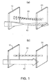
- FIG. 1 shows a phenomenon for selectively transmitting light in a TN-LCD used widely.
- an angle between the polarization axes between a light source side polarizer plate 10 and a viewer side polarizer plate 20 is 90°.
- Nematic liquid crystal molecules 30 are filled between the two polarizer plates and the liquid crystal molecules 30, which are close to the polarizer plates, are aligned in the same directions as the polarization axes of the polarizer plates. Accordingly, the alignment directions of the liquid crystal molecules which are close to the two polarizer plates are orthogonal to each other, similar to the polarizer plates.
- the liquid crystal molecules in a middle portion are twisted as shown in the drawing.
- light 40 polarized by the light source side polarizer plate rotates by 90° by the nematic liquid crystal molecules and, as a result, passes through the viewer side polarizer plate.
- the liquid crystal molecules 30 are arranged parallel to the direction of the electrical field as shown in FIG. 1b . Accordingly, the light 40 which passes through the light source side polarizer plate 10 does not rotate and reaches the viewer side polarizer plate 20 in the direction polarized by the light source side polarizer plate such that the light does not transmit through the viewer side polarizer plate 20 which rotates by 90° with respect to the light source side polarizer plate 10.
- the LCD controls the transmission and blocking of the light by selectively applying the electrical field to each pixel using the above-described phenomenon.
- the contrast characteristic is improved when the light is surely transmitted and blocked such that a bright state and a dark state appear.
- the contrast characteristic is improved when the light is surely transmitted and blocked such that a bright state and a dark state appear.
- No problem is caused in the contrast characteristic when a display device is viewed from the front side, but the light leakage is unlikely to be perfectly prevented in the dark state when the display device is viewed at an inclination angle.
- the light is blocked by providing a polarizer plate having a transmission axis perpendicular to the light polarized linearly at the viewer side using a polarization phenomenon.
- the light which reaches the viewer side polarizer plate is not perfectly linearly polarized, a portion of the light may be leaked.
- Such a phenomenon may occur when the light travels in an inclination direction (in the viewer's direction), not in a vertical direction. That is, the dark state is perfectly implemented when the nematic liquid crystal molecules are aligned parallel to the traveling direction of the light as shown in FIG. 1b . Accordingly, since the alignment direction of the liquid crystal molecules and the traveling direction of the light are not perfectly parallel to each other when the light travels in the inclination direction, an additional phase variation occurs and thus the light is not perfectly blocked.
- the light may not be perfectly blocked in the dark state by the splay alignment of the liquid crystal layer.
- Korean Patent Publication No. 10-0376378 discloses the technology of improving the gray-scale characteristic and reducing light leakage using an O film.
- variations in light leakage amount among gray scales according to viewing angles are minimized by an O-plate compensator having an inclination angle.
- light leakage amount can be properly controlled according to the viewing angles, it is possible to manufacture a LCD having a high gray-scale characteristic regardless of the viewing angle.
- US 2005/0219447 A1 discloses an optically biaxial film for use as a retardation or compensation film in optical devices like liquid crystal displays.
- the in-plate retardation value of the biaxial film of the compensation stack is 120 nm.
- the present invention has been made to solve the foregoing problems of the prior art and therefore an aspect of the present invention is to provide an integrated O film for improving a viewing angle of a TN-LCD having a improved contrast characteristic, gray-scale characteristic or color characteristic by blocking various kinds of factors for causing light leakage.
- an integrated O film according to claim 1 there is provided an integrated O film according to claim 1.
- the value N z of the negative B film expressed by Equation 8 may be 0.1 to 2.
- N z n z - n y n x - n y
- n x , n y , and n z denote refractive indexes of x, y and zdirections, respectively.
- the thickness retardation value of the negative film may be -50 to -150 nm.
- the value N z of the negative B film may be 0.3 to 1.
- An average tilt angle of the positive O film expressed by Equation 9 may be 30° to 50° and a maximum value of the tilt angle may be 50° to 90°.
- ⁇ average ⁇ 0 d ⁇ z d z d
- d denotes a thickness of the film and ⁇ (z) denotes a tilt angle of the film in a vertical position z.
- An in-plane retardation value of the positive 0 film may be 50 to 150 nm.
- the positive O film includes nematic liquid crystal.
- An alignment film interposed between the negative B film and the positive O film is further included.
- the alignment film is an acrylic-based alignment film.
- the alignment film may be an optical alignment film having an alignment characteristic by irradiation of polarized ultraviolet rays.
- the alignment film may include polynorbomene cinnamate or polyimide cinnamate.
- an integrated O film according to the present invention is manufactured by laminating a positive O film and a negative B film under an optimal condition. Accordingly, it is possible to prevent light leakage in all directions and to manufacture a TN-LCD capable of improving a contrast characteristic, gray scale characteristic and color characteristic by using the integrated O film according to the present invention.
- FIGS. 1A and 1B resepctively are views showing a bright state and a dark state of a TN-LCD
- FIG. 2 is a schematic view showing the splay alignment of liquid crystal molecules when an electrical field is applied to a TN-LCD;
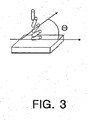
- FIG. 3 is a schematic view showing the splay alignment state of a positive O film
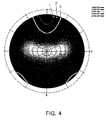
- FIG. 4 is a graph showing a contrast characteristic distribution of a TN-LCD according to Embodiment 1 of the present invention.
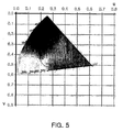
- FIG. 5 is a graph showing a color characteristic distribution of the TN-LCD according to Embodiment 1 of the present invention.
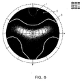
- FIG. 6 is a graph showing a contrast characteristic distribution of a TN-LCD according to Embodiment 2 of the present invention.
- FIG. 7 is a graph showing a color characteristic distribution of the TN-LCD according to Embodiment 2 of the present invention.
- FIG. 8 is a graph showing a contrast characteristic distribution of a TN-LCD including a negative O film, for the purpose of comparison with the present invention.
- FIG. 9 is a graph showing a color characteristic distribution of a TN-LCD including a negative O film, for the purpose of comparison with the present invention.
- light leakage occurs because light polarized by a light source side polarizer plate is subjected to a retardation before reaching a viewer side polarizer plate and thus the light cannot reach the viewer side polarizer plate in a perfectly linearly polarized state vertical to a transmission axis of the viewer side polarizer plate.
- the retardation for causing light leakage is classified into three types as follows:
- a retardation which occurs by a splay alignment portion of a TN-LCD liquid crystal molecules in a portion close to an alignment film or in a gray state may be aligned in a splay alignment manner
- an integrated O film refers to a lamination of a positive O film and a negative B film
- an O film refers to an 0 film layer.
- the O film is to compensate a retardation which occurs (that is, a retardation which occurs due to a splay alignment) when, since an electrical field is applied to liquid crystal molecules, the liquid crystal molecules are not vertically aligned in the boundary between an alignment film and the liquid crystal, that is, are aligned parallel to the alignment direction of the alignment film, and the liquid crystal molecules become gradually more tilted in the direction of the electrical field.
- a retardation which occurs that is, a retardation which occurs due to a splay alignment
- the molecules of the 0 film are preferably splay-aligned.
- an average tilt angle ⁇ average defined by Equation 9 is in a range of 30° to 50° and a maximum tilt angle is preferably in a range of 50° to 90° and more preferably in a range of 60° to 90°.
- ⁇ average ⁇ 0 d ⁇ z d z d
- d denotes the thickness of the film and ⁇ (z) denotes a tilt angle at a vertical position z in the film.
- the 0 film is preferably formed of nematic liquid crystal. That is, the O film is formed of liquid crystal, for the splay or oblique alignment.
- an optical axis separation angle occurs.
- the optical axis seperation angle indicates an angle between the alignment direction of the liquid crystal molecules and a rubbing direction for aligning the liquid crystal molecules.
- front contrast ratio and color characteristic deteriorate. That is, when the optical axis separation angle occurs, light leakage occurs at the front side and more paricularly blue light leakage significantly increases. Accordingly, a front color becomes blue and the contrast deteriorates.
- the optical axis separation angle should be managed within ⁇ 0.5°.
- the discotic liquid crystal molecule has a coin shape and is symmetrical with respect to all directions, the discotic liquid crystal molecules are unlikely to be aligned in a uniform direction and thus are not suitable for managing the optical axis separation angle.
- the nematic liquid crystal molecule has a rod shape, the nematic liquid crystal molecules are easily aligned in a rubbing direction and are suitable for managing the optical axis separation angle.
- the nematic liquid crystal is preferably used.
- the negative B film is an anisotropic film having the following relationship when the refractive indexes of x, y, and z directions are respectively n x , n y , and n z .
- the negative B film respectively has optical axes in a direction c (vertical to the surface of the film) and a direction c (parallel to the surface of the film) and performs a function similar to that of a negative C plate by the optical axis component of the direction c. Accordingly, a retardation which occurs by a positive C plate formed of liquid crystal by emitting light at an inclination angle is cancelled by a negative C plate.
- the direction a which is the other optical axis of the negative B film, serves to cancel a retardation which may occur when light enters the polarizer plate at an inclination angle.
- the negative B film may be preferably a transversely-stretched film.
- a transversely-stretched film a biaxially stretched cyclo-olefin polymer (COP) film, a biaxially stretched polycarbonate (PC) film, a uniaxially stretched triacetate cellulose (TAC) and poly norbornene film may be used.
- COP biaxially stretched cyclo-olefin polymer
- PC biaxially stretched polycarbonate
- TAC uniaxially stretched triacetate cellulose
- poly norbornene film may be used.
- a biaxial liquid crystal may also be used.
- the positive O film and the negative B film serve to cancel the three retardations.
- the positive O film and the negative B film must be used by the following proper combination such that the effect of the present invention can be obtained.
- a lamination of the O film and the B film is used.
- the optical axis of the 0 film and the optical axis (optical axis parallel to the surface of the film out of the two optical axes) of the B film need to be orthogonal to each other.
- the O film and the B film have adequate retardation values in order to cancel the retardation effect due to the inclination angle.
- each film has an in-plane retardation value according to Equation 5 and a thickness retardation value according to Equation 6, all of which are in respective adequate ranges.
- Equation 6 denotes the thickness of the film and n x , n y and n z denote the refractive indexes of x, y, and z directions.
- Thickness - retardation value R tn d ⁇ n z - n y
- the in-plane retardation value R in of the B film for preventing light leakage when light reaches the polarizer plate at the inclination angle should be 150 to 250 nm. If the in-plane retardation value is less than 150 nm, the light leakage significantly increases and thus a contrast ratio decreases. In contrast, if in-plane retardation value is greater than 250 nm, the color of the dark state unpreferably varies.
- a value N z expressed by Equation 8 is preferably in a range of 0.1 to 2 in order to further improve the contrast ratio. If the value N z is less than 0.1, the contrast ratio decreases. In contrast, if the value N z is greater than 2, a variation in color of the dark state unpreferably increases. It is more preferable that the value N z is in a range of 0.3 to 1.
- N z n z - n y n x - n y
- Equation 6 indicates a ratio of the thickness retardation value R th to the in-plane retardation value R in . Accordingly, since the preferable range of the in-plane retardation value R in is previously obtained, the range of the thickness retardation value can be obtained by Equation 6.
- the thickness retardation value of the B film for further improving a contrast ratio while satisfying Equation 6 is -50 to -150 nm.
- the integrated O film is formed by laminating the 0 film on the B film.
- the retardation value of the 0 film should be determined in consideration of the retardation value of the B film. According to the researched result of the present inventors, it is preferable that the proper in-plane retardation value of the 0 film is 50 to 150 nm and the thickness retardation value is 50 to 150 nm.
- the various retardations can be cancelled by the combination of the positive O film and the negative B film. Accordingly, a good constrast characteristic, color characteristic and gray scale characteristic can be obtained in a wide viewing angle.
- an alignment film may be further formed on the B film base in order to align the 0 film on the B film in a necessary direction.
- the alignment film is preferably an acrylic-based alignment film, for example, an alignment film including a mixture of penta acrylate and modified poly vinyl alcohol (PVA).
- PVA penta acrylate and modified poly vinyl alcohol
- an optical alignment film having an alignment characteristic by irradiation of polarized ultraviolet rays may be used as the alignment film.
- the example of the optical alignment film may include polynorbomene cinnamate or polyimide cinnamate.
- the present invention discloses a polarizer plate and a TN-LCD including the integrated O film including the O film and the B film.
- the polarization film, the B film and the O film are laminated in this order, or the polarization film, the O film and the B film are laminated in this order (That is, the integrated O film is laminated on the polarization film).
- the B film is laminated such that the in-plane optical axis of the B film is orthogonal to the absorption axis of the polarizer plate.
- the O film is laminated such that the optical axis of the O film is orthogonal to the in-plane optical axis of the B film.
- Integrated O films laminated on polarizer plates may have the characteristic of the integrated O film according to the present invention.
- the present invention also discloses a TN-LCD including a pair of glass plates which face each other, twisted nematic liquid crystal filled between the glass plates, and polarizer plates attached to the outsides of the glass plates. That is, the TN-LCD according to the present invention includes the polarizer plate, the glass plate, the liquid crystal, the glass plate and the polarizer plate, all of which are arranged in this order.
- the TN-LCD according to the present invention includes the polarizer plate having the characteristic of the above-described lamination.
- the integrated O film which is the lamination included in the polarizer plate includes all the characteristics of the integrated O film according to the present invention.
- a polarization film is aligned at an angle of 45° with horizontal direction of LCD Panel and the absorption axis of the polarization film is parallel to the optical axis of the LCD panel.
- An integrated 0 film was interposed between the LCD panel and the polarization film.
- the integrated O film was manufactured by coating a negative B film with a splay-aligned liquid crystal film (0 film).
- the optical axis of the O film was orthogonal to that of the B film.
- the absorption axis of the polarization film was parallel to the optical axis of the O film and the absorption axis of the polarization film was orthogonal to the optical axis of the negative B film.
- a counter polarization film was provided on the outside of the LCD panel.
- the absorption axis of the counter polarization film was aligned at an angle of 135° with horizontal direction of LCD Panel and an integrated O film was interposed between the LCD panel and the counter polarization film.
- the absorption axis of the counter polarization film was parallel to the optical axis of the O film and was orthogonal to the optical axis of the negative B film, similar to the above-descried polarization film.
- the contrast characteristic is shown in FIG. 4 and the color characteristic is shown in FIG. 5 .
- line 1 indicates a boundary of an area having a contrast ratio of above 15:1
- line 2 indicates an area having a contrast ratio of above 20:1
- line 3 indicates an area having a contrast ratio of above 30:1. From the drawings, it can be seen that the area having the contrast ratio of above 15:1 is widely distributed and a variation in color characteristic is ⁇ u ⁇ 0.015 and ⁇ v ⁇ 0.15, that is, is very small.
- a TN-LCD of Embodiment 2 is similar to that of Embodiment 1 except that the in-plane retardation value of the B film included in the integrated O film is 180 nm and the thickness retardation value thereof is 100 nm.
- the optical characteristic and the color characteristic of the TN-LCD of Embodiment 2 were evaluated.
- the contrast characteristic is shown in FIG. 6 and the color characteristic is shown in FIG. 7 .
- line 1 indicates a boundary of an area having a contrast ratio of above 15:1
- line 2 indicates an area having a contrast ratio of above 20:1
- line 3 indicates an area having a contrast ratio of above 30:1. From the drawings, it can be seen that the area having the contrast ratio of above 15:1 is widely distributed and a variation in color characteristic is slightly larger than that of Embodiment 1, but is very small.
- a TN-LCD of Comparative Example 1 is similar to that of Embodiment 1 except that WV-EA compensation film (made by Fuji Photo Film Co., Ltd) is used as a compensation film.
- WV-EA compensation film made by Fuji Photo Film Co., Ltd.
- the optical characteristic and the color characteristic of the TN-LCD of Comparative Example 1 were evaluated.
- the contrast characteristic is shown in FIG. 8 and the color characteristic is shown in FIG. 9 .
- the compensation film manufactured by Comparative example 1 has the same contrast characteristic as the embodiments of the present invention.
- Line 1 varies depending on a viewing angle.
- the reason why the color coordinate is shifted is supposed because the negative O film was used. That is, in the negative O film, discotic liquid crystal is used as the liquid crystal included in the O film. As described above, the discotic liquid crystal is more unlikely to be aligned in an alignment axis, compared with nematic liquid crystal used in a positive O film. As a result, an optical axis separation angle occurs.
- the comparative example using the negative O film has a color characteristic inferior to the embodiments of the present invention.
- an integrated 0 film according to the present invention is ma nufactured by laminating a positive O film and a negative B film under an optimal condition. Accordingly, it is possible to prevent light leakage in all directions and to manufacture a TN-LCD capable of improving a contrast characteristic, gray scale characteristic and color characteristic by using the integrated O film according to the present invention.
Description
- The present invention relates to an integrated O film for improving a viewing angle of a twisted nematic liquid crystal display (TN-LCD), and more particularly, a compensation film, which is capable of improving a contrast characteristic at a front side and an inclination angle and minimizing a color variation according to a viewing angle in a dark state.
- A liquid crystal display (LCD) is a display device for implementing a desired image by selectively transmitting light emitted from a backlight using a polarization phenomenon of liquid crystal.
-
FIG. 1 shows a phenomenon for selectively transmitting light in a TN-LCD used widely. As shown inFIG. 1A , an angle between the polarization axes between a light sourceside polarizer plate 10 and a viewerside polarizer plate 20 is 90°. Nematicliquid crystal molecules 30 are filled between the two polarizer plates and theliquid crystal molecules 30, which are close to the polarizer plates, are aligned in the same directions as the polarization axes of the polarizer plates. Accordingly, the alignment directions of the liquid crystal molecules which are close to the two polarizer plates are orthogonal to each other, similar to the polarizer plates. In addition, the liquid crystal molecules in a middle portion are twisted as shown in the drawing. - Accordingly,
light 40 polarized by the light source side polarizer plate rotates by 90° by the nematic liquid crystal molecules and, as a result, passes through the viewer side polarizer plate. - However, when an electrical field is applied to the
liquid crystal molecules 30, theliquid crystal molecules 30 are arranged parallel to the direction of the electrical field as shown inFIG. 1b . Accordingly, thelight 40 which passes through the light sourceside polarizer plate 10 does not rotate and reaches the viewerside polarizer plate 20 in the direction polarized by the light source side polarizer plate such that the light does not transmit through the viewerside polarizer plate 20 which rotates by 90° with respect to the light sourceside polarizer plate 10. - The LCD controls the transmission and blocking of the light by selectively applying the electrical field to each pixel using the above-described phenomenon.
- In the LCD, the contrast characteristic is improved when the light is surely transmitted and blocked such that a bright state and a dark state appear. In particular, when light leakage is minimized in the dark state, it is possible to improve the contrast characteristic. No problem is caused in the contrast characteristic when a display device is viewed from the front side, but the light leakage is unlikely to be perfectly prevented in the dark state when the display device is viewed at an inclination angle. As described above, in the LCD, the light is blocked by providing a polarizer plate having a transmission axis perpendicular to the light polarized linearly at the viewer side using a polarization phenomenon. However, when the light which reaches the viewer side polarizer plate is not perfectly linearly polarized, a portion of the light may be leaked.
- Such a phenomenon may occur when the light travels in an inclination direction (in the viewer's direction), not in a vertical direction. That is, the dark state is perfectly implemented when the nematic liquid crystal molecules are aligned parallel to the traveling direction of the light as shown in
FIG. 1b . Accordingly, since the alignment direction of the liquid crystal molecules and the traveling direction of the light are not perfectly parallel to each other when the light travels in the inclination direction, an additional phase variation occurs and thus the light is not perfectly blocked. - Another reason why the light leakage occurs in the dark state is because the liquid crystal molecules are aligned in a horizontal direction equal to the orientation of an alignment film, not parallel to the direction of the electrical field, in the boundary between the alignment film and the liquid crystal (that is, the polarizer plate side), and become aligned parallel to the direction of the electrical field as getting away from the boundary between the alignment film and the liquid crystal, as shown in
FIG. 2 . Accordingly, there is caused a so-called splay alignment that the inclination angles of the liquid crystal molecules gradually increase to be close to 90 from the boundary between the alignment film and the liquid crystal to the center of the liquid crystal layer. - The light may not be perfectly blocked in the dark state by the splay alignment of the liquid crystal layer.
- Conventionally, a variety of technologies were suggested in order to prevent the light leakage. For example, Korean Patent Publication No.
10-0376378 - However, in this technology, since the O film is directly formed on a glass substrate, productivity deteriorates. That is, in order to manufacture the O-plate compensator, a low pretilt alignment layer and high pretilt alignment layer are formed on the glass substrate. In this case, it takes much time to perform the process of forming the layers on the glass substrate and it is difficult to manage the substrate.
- In addition, in the conventional method, light leakage which occurs by the splay alignment of the liquid crystal molecules can be reduced. However, the light leakage due to the +C alignment of liquid crystal molecules (that is, since the liquid crystal molecules are aligned parallel to the direction of the electrical field, the light can be prevented from leaking to the front side. However, when the light travels in an inclination direction, a retardation occurs and thus a perfect dark state cannot appear) is unlikely to be reduced.
- When light reaches the polarizer plate at an inclination angle, a slight phase retardation occurs in the polarizer plate, thereby causing light leakage. However, in the Korean Patent Publication No.
10-0376378 -
US 2005/0219447 A1 discloses an optically biaxial film for use as a retardation or compensation film in optical devices like liquid crystal displays. In one example, the in-plate retardation value of the biaxial film of the compensation stack is 120 nm. - The present invention has been made to solve the foregoing problems of the prior art and therefore an aspect of the present invention is to provide an integrated O film for improving a viewing angle of a TN-LCD having a improved contrast characteristic, gray-scale characteristic or color characteristic by blocking various kinds of factors for causing light leakage.
- According to an aspect of the present invention, there is provided an integrated O film according to
claim 1. - The value Nz of the negative B film expressed by Equation 8 may be 0.1 to 2.
-

- where, nx, ny, and nz denote refractive indexes of x, y and zdirections, respectively.
- The thickness retardation value of the negative film may be -50 to -150 nm.
- More preferably, the value Nz of the negative B film may be 0.3 to 1.
- An average tilt angle of the positive O film expressed by Equation 9 may be 30° to 50° and a maximum value of the tilt angle may be 50° to 90°.
-

- where, d denotes a thickness of the film and θ(z) denotes a tilt angle of the film in a vertical position z.
- An in-plane retardation value of the positive 0 film may be 50 to 150 nm.
- The positive O film includes nematic liquid crystal.
- An alignment film interposed between the negative B film and the positive O film is further included.
- The alignment film is an acrylic-based alignment film.
- The alignment film may be an optical alignment film having an alignment characteristic by irradiation of polarized ultraviolet rays.
- The alignment film may include polynorbomene cinnamate or polyimide cinnamate.
- As described above, an integrated O film according to the present invention is manufactured by laminating a positive O film and a negative B film under an optimal condition. Accordingly, it is possible to prevent light leakage in all directions and to manufacture a TN-LCD capable of improving a contrast characteristic, gray scale characteristic and color characteristic by using the integrated O film according to the present invention.
- The above and other aspects, features and other advantages of the present invention will be more clearly understood from the following detailed description taken in conjunction with the accompanying drawings, in which:
-
FIGS. 1A and 1B resepctively are views showing a bright state and a dark state of a TN-LCD; -
FIG. 2 is a schematic view showing the splay alignment of liquid crystal molecules when an electrical field is applied to a TN-LCD; -
FIG. 3 is a schematic view showing the splay alignment state of a positive O film; -
FIG. 4 is a graph showing a contrast characteristic distribution of a TN-LCD according toEmbodiment 1 of the present invention; -
FIG. 5 is a graph showing a color characteristic distribution of the TN-LCD according toEmbodiment 1 of the present invention; -
FIG. 6 is a graph showing a contrast characteristic distribution of a TN-LCD according toEmbodiment 2 of the present invention; -
FIG. 7 is a graph showing a color characteristic distribution of the TN-LCD according toEmbodiment 2 of the present invention; -
FIG. 8 is a graph showing a contrast characteristic distribution of a TN-LCD including a negative O film, for the purpose of comparison with the present invention; and -
FIG. 9 is a graph showing a color characteristic distribution of a TN-LCD including a negative O film, for the purpose of comparison with the present invention. - Hereinafter, the present invention will be described in detail.
- As described above, light leakage occurs because light polarized by a light source side polarizer plate is subjected to a retardation before reaching a viewer side polarizer plate and thus the light cannot reach the viewer side polarizer plate in a perfectly linearly polarized state vertical to a transmission axis of the viewer side polarizer plate.
- The retardation for causing light leakage is classified into three types as follows:
- 1) A retardation which occurs when a TN-LCD is vertically erected, a viewing angle is not parallel to the alignment direction of the liquid crystal molecules, and thus light travels at the viewing angle,
- 2) A retardation which occurs by a splay alignment portion of a TN-LCD (liquid crystal molecules in a portion close to an alignment film or in a gray state may be aligned in a splay alignment manner), and
- 3) A retardation which occurs when light obliquely enters a polarizer plate.
- Accordingly, in order to prevent light from leaking, all the above-described retardations must be compensated.
- The inventors of the present invention carry out research on such problems and confirm that all the retardations which occur in various patterns can be compensated when a positive 0 film and a negative biaxial (B) film are arranged under an adequate condition. Hereinafter, an integrated O film refers to a lamination of a positive O film and a negative B film, and an O film refers to an 0 film layer.
- Among the films, the O film is to compensate a retardation which occurs (that is, a retardation which occurs due to a splay alignment) when, since an electrical field is applied to liquid crystal molecules, the liquid crystal molecules are not vertically aligned in the boundary between an alignment film and the liquid crystal, that is, are aligned parallel to the alignment direction of the alignment film, and the liquid crystal molecules become gradually more tilted in the direction of the electrical field.
- As shown in
FIG. 3 , the molecules of the 0 film are preferably splay-aligned. In the splay alignment of the molecules of the O film, an average tilt angle θaverage defined by Equation 9 is in a range of 30° to 50° and a maximum tilt angle is preferably in a range of 50° to 90° and more preferably in a range of 60° to 90°. -

- where, d denotes the thickness of the film and θ(z) denotes a tilt angle at a vertical position z in the film.
- At this time, the 0 film is preferably formed of nematic liquid crystal. That is, the O film is formed of liquid crystal, for the splay or oblique alignment. When the O film is formed of discotic liquid cyrstal, an optical axis separation angle occurs. The optical axis seperation angle indicates an angle between the alignment direction of the liquid crystal molecules and a rubbing direction for aligning the liquid crystal molecules. When the optical axis separation angle occurs, front contrast ratio and color characteristic deteriorate. That is, when the optical axis separation angle occurs, light leakage occurs at the front side and more paricularly blue light leakage significantly increases. Accordingly, a front color becomes blue and the contrast deteriorates. In order to prevent contrast and color failures due to the optical axis seperation angle, the optical axis separation angle should be managed within ±0.5°. However, since the discotic liquid crystal molecule has a coin shape and is symmetrical with respect to all directions, the discotic liquid crystal molecules are unlikely to be aligned in a uniform direction and thus are not suitable for managing the optical axis separation angle. In contrast, since the nematic liquid crystal molecule has a rod shape, the nematic liquid crystal molecules are easily aligned in a rubbing direction and are suitable for managing the optical axis separation angle. Thus, the nematic liquid crystal is preferably used.
- The negative B film is an anisotropic film having the following relationship when the refractive indexes of x, y, and z directions are respectively nx, ny, and nz.
-

- The negative B film respectively has optical axes in a direction c (vertical to the surface of the film) and a direction c (parallel to the surface of the film) and performs a function similar to that of a negative C plate by the optical axis component of the direction c. Accordingly, a retardation which occurs by a positive C plate formed of liquid crystal by emitting light at an inclination angle is cancelled by a negative C plate.
- The direction a, which is the other optical axis of the negative B film, serves to cancel a retardation which may occur when light enters the polarizer plate at an inclination angle.
- The negative B film may be preferably a transversely-stretched film. As the transversely-stretched film, a biaxially stretched cyclo-olefin polymer (COP) film, a biaxially stretched polycarbonate (PC) film, a uniaxially stretched triacetate cellulose (TAC) and poly norbornene film may be used. A biaxial liquid crystal may also be used.
- Accordingly, the positive O film and the negative B film serve to cancel the three retardations. However, the positive O film and the negative B film must be used by the following proper combination such that the effect of the present invention can be obtained.
- A lamination of the O film and the B film is used. In the lamination, the optical axis of the 0 film and the optical axis (optical axis parallel to the surface of the film out of the two optical axes) of the B film need to be orthogonal to each other.
- In the lamination, the O film and the B film have adequate retardation values in order to cancel the retardation effect due to the inclination angle.
- That is, each film has an in-plane retardation value according to Equation 5 and a thickness retardation value according to Equation 6, all of which are in respective adequate ranges. In Equations, d denotes the thickness of the film and nx, ny and nz denote the refractive indexes of x, y, and z directions.
-

-

- The present inventors obtained the researched result that the in-plane retardation value Rin of the B film for preventing light leakage when light reaches the polarizer plate at the inclination angle should be 150 to 250 nm. If the in-plane retardation value is less than 150 nm, the light leakage significantly increases and thus a contrast ratio decreases. In contrast, if in-plane retardation value is greater than 250 nm, the color of the dark state unpreferably varies.
- If the in-plane retardation value of the B film is in the above-described range, a value Nz expressed by Equation 8 is preferably in a range of 0.1 to 2 in order to further improve the contrast ratio. If the value Nz is less than 0.1, the contrast ratio decreases. In contrast, if the value Nz is greater than 2, a variation in color of the dark state unpreferably increases. It is more preferable that the value Nz is in a range of 0.3 to 1.
-

- Equation 6 indicates a ratio of the thickness retardation value Rth to the in-plane retardation value Rin. Accordingly, since the preferable range of the in-plane retardation value Rin is previously obtained, the range of the thickness retardation value can be obtained by Equation 6.
- The thickness retardation value of the B film for further improving a contrast ratio while satisfying Equation 6 is -50 to -150 nm.
- The integrated O film is formed by laminating the 0 film on the B film. The retardation value of the 0 film should be determined in consideration of the retardation value of the B film. According to the researched result of the present inventors, it is preferable that the proper in-plane retardation value of the 0 film is 50 to 150 nm and the thickness retardation value is 50 to 150 nm.
- The various retardations can be cancelled by the combination of the positive O film and the negative B film. Accordingly, a good constrast characteristic, color characteristic and gray scale characteristic can be obtained in a wide viewing angle.
- In the integrated O film, an alignment film may be further formed on the B film base in order to align the 0 film on the B film in a necessary direction. At this time, the alignment film is preferably an acrylic-based alignment film, for example, an alignment film including a mixture of penta acrylate and modified poly vinyl alcohol (PVA). Instead of the acrylic-based alignment film, an optical alignment film having an alignment characteristic by irradiation of polarized ultraviolet rays may be used as the alignment film. The example of the optical alignment film may include polynorbomene cinnamate or polyimide cinnamate.
- The present invention discloses a polarizer plate and a TN-LCD including the integrated O film including the O film and the B film.
- In the polarizer plate, the polarization film, the B film and the O film are laminated in this order, or the polarization film, the O film and the B film are laminated in this order (That is, the integrated O film is laminated on the polarization film). The B film is laminated such that the in-plane optical axis of the B film is orthogonal to the absorption axis of the polarizer plate. The O film is laminated such that the optical axis of the O film is orthogonal to the in-plane optical axis of the B film.
- Integrated O films laminated on polarizer plates may have the characteristic of the integrated O film according to the present invention.
- The present invention also discloses a TN-LCD including a pair of glass plates which face each other, twisted nematic liquid crystal filled between the glass plates, and polarizer plates attached to the outsides of the glass plates. That is, the TN-LCD according to the present invention includes the polarizer plate, the glass plate, the liquid crystal, the glass plate and the polarizer plate, all of which are arranged in this order. The TN-LCD according to the present invention includes the polarizer plate having the characteristic of the above-described lamination.
- Accordingly, the integrated O film which is the lamination included in the polarizer plate includes all the characteristics of the integrated O film according to the present invention.
- When the above-described TN-LCD is used, it is possible to minimize light leakage due to the retardaton compensation effect of the integrated O film.
-
Embodiment 1 - A LCD having a dielectric anisotropy of Δε>0 and refractive indexes of liquid crystal of ne =1.595 and no =1.5 and including an LCD panel having a thickness of 4.8□ and a compensation film was manufactured. A polarization film is aligned at an angle of 45° with horizontal direction of LCD Panel and the absorption axis of the polarization film is parallel to the optical axis of the LCD panel. An integrated 0 film was interposed between the LCD panel and the polarization film.
- The integrated O film was manufactured by coating a negative B film with a splay-aligned liquid crystal film (0 film). The optical axis of the O film was orthogonal to that of the B film. The absorption axis of the polarization film was parallel to the optical axis of the O film and the absorption axis of the polarization film was orthogonal to the optical axis of the negative B film.
- A counter polarization film was provided on the outside of the LCD panel. The absorption axis of the counter polarization film was aligned at an angle of 135° with horizontal direction of LCD Panel and an integrated O film was interposed between the LCD panel and the counter polarization film. The absorption axis of the counter polarization film was parallel to the optical axis of the O film and was orthogonal to the optical axis of the negative B film, similar to the above-descried polarization film.
- The 0 film included in the integrated film has an in-plane retardation value of Rin =60 nm and is formed of nematic liquid crystal. In the splay alignment of the O film, an average tilt angle expressed by
Equation 3 was 45°. The in-plane retardation value of the negative B film is Rin =190 nm and the thickness retardation value thereof is Rth =-100 nm. - The contrast characteristic is shown in
FIG. 4 and the color characteristic is shown inFIG. 5 . In the drawings,line 1 indicates a boundary of an area having a contrast ratio of above 15:1,line 2 indicates an area having a contrast ratio of above 20:1, andline 3 indicates an area having a contrast ratio of above 30:1. From the drawings, it can be seen that the area having the contrast ratio of above 15:1 is widely distributed and a variation in color characteristic is Δu<0.015 and Δv<0.15, that is, is very small. -
Embodiment 2 - A TN-LCD of
Embodiment 2 is similar to that ofEmbodiment 1 except that the in-plane retardation value of the B film included in the integrated O film is 180 nm and the thickness retardation value thereof is 100 nm. The optical characteristic and the color characteristic of the TN-LCD ofEmbodiment 2 were evaluated. - The contrast characteristic is shown in
FIG. 6 and the color characteristic is shown inFIG. 7 . In the drawings,line 1 indicates a boundary of an area having a contrast ratio of above 15:1,line 2 indicates an area having a contrast ratio of above 20:1, andline 3 indicates an area having a contrast ratio of above 30:1. From the drawings, it can be seen that the area having the contrast ratio of above 15:1 is widely distributed and a variation in color characteristic is slightly larger than that ofEmbodiment 1, but is very small. - Comparative Example 1
- A TN-LCD of Comparative Example 1 is similar to that of
Embodiment 1 except that WV-EA compensation film (made by Fuji Photo Film Co., Ltd) is used as a compensation film. The optical characteristic and the color characteristic of the TN-LCD of Comparative Example 1 were evaluated. - The contrast characteristic is shown in
FIG. 8 and the color characteristic is shown inFIG. 9 . As can be seen from theFIG. 8 , the compensation film manufactured by Comparative example 1 has the same contrast characteristic as the embodiments of the present invention. However, there is a phenomenon that the front color characteristic deteriorates as shown inFIG. 9 . That is, in the comparative example, an optical axis separation angle is widely distributed and a variation in color characteristic shown inFIG. 9 is Δv>0.2 and Δu>0.03, which is larger than those shown inFIGS. 5 and7 .Line 1 varies depending on a viewing angle. - The reason why the color coordinate is shifted is supposed because the negative O film was used. That is, in the negative O film, discotic liquid crystal is used as the liquid crystal included in the O film. As described above, the discotic liquid crystal is more unlikely to be aligned in an alignment axis, compared with nematic liquid crystal used in a positive O film. As a result, an optical axis separation angle occurs.
- Accordingly, the comparative example using the negative O film has a color characteristic inferior to the embodiments of the present invention.
- As described above, an integrated 0 film according to the present invention is ma nufactured by laminating a positive O film and a negative B film under an optimal condition. Accordingly, it is possible to prevent light leakage in all directions and to manufacture a TN-LCD capable of improving a contrast characteristic, gray scale characteristic and color characteristic by using the integrated O film according to the present invention.
Claims (7)
- An integrated O film comprising:a transversely-stretched negative biaxial film B film; a positive O film; and an alignment film interposed between the transversely-stretched negative B film and the positive O film,characterized in thatthe alignment film is an acrylic-based alignment film,the positive 0 film includes nematic liquid crystal,the transversely-stretched negative B film is an anisotropic film having the following relationship of Equation 4, andan in-plane retardation value of the transversely-stretched negative B film, as expressed by Equation 5, is 150 to 250 nm:


wherein nx, ny and nz denote refractive indexes of x, y and z directions, respectively, and d denotes the thickness of the film. - The integrated O film according to claim 1, wherein a value Nz of the transversely-stretched negative B film as expressed by Equation 8 is 0.1 to 2.

- The integrated O film according to claim 2, wherein a thickness retardation value of the transversely-stretched negative B film as expressed by Equation 6, is -50 to -150 nm

- The integrated O film according to claim 2, wherein the value Nz of the transversely-stretched negative B film is 0.3 to 1.
- The integrated O film according to claim 1, wherein an average tilt angel of the positive O film expressed by Equation 9 is 30° to 50° and a maximum value of the tilt angle is 50° to 90°.

where d denotes a thickness of the film and θ(z) denotes a tilt angle of the film in a vertical position z. - The integrated O film according to any one of claims 1 to 6, wherein an in-plane retardation value of the positive O film as expressed by Equation 5, is 50 to 150 nm

- The integrated 0 film according to claim 1, wherein the alignment film is an optical alignment film having an alignment characteristic by irradiation of polarized ultraviolet rays.
Priority Applications (1)
| Application Number | Priority Date | Filing Date | Title |
|---|---|---|---|
| EP13191247.9A EP2693243B1 (en) | 2006-06-08 | 2007-06-05 | Integrated O Film for Improving viewing angle of TN-LCD, and Polarizer Plate and TN-LCD including the same |
Applications Claiming Priority (2)
| Application Number | Priority Date | Filing Date | Title |
|---|---|---|---|
| KR1020060051636A KR100907818B1 (en) | 2006-06-08 | 2006-06-08 | An integrated O-film for improving the TN-LCD viewing angle, a polarizing plate laminate containing the same, and a TN-LCD |
| PCT/KR2007/002733 WO2007142458A1 (en) | 2006-06-08 | 2007-06-05 | Integrated o film for improving viewing angle of tn-lcd, and polarizer plate and tn-lcd including the same |
Related Child Applications (2)
| Application Number | Title | Priority Date | Filing Date |
|---|---|---|---|
| EP13191247.9A Division EP2693243B1 (en) | 2006-06-08 | 2007-06-05 | Integrated O Film for Improving viewing angle of TN-LCD, and Polarizer Plate and TN-LCD including the same |
| EP13191247.9 Division-Into | 2013-11-01 |
Publications (3)
| Publication Number | Publication Date |
|---|---|
| EP2024766A1 EP2024766A1 (en) | 2009-02-18 |
| EP2024766A4 EP2024766A4 (en) | 2011-06-08 |
| EP2024766B1 true EP2024766B1 (en) | 2013-12-11 |
Family
ID=38801662
Family Applications (2)
| Application Number | Title | Priority Date | Filing Date |
|---|---|---|---|
| EP07793103.8A Active EP2024766B1 (en) | 2006-06-08 | 2007-06-05 | Integrated o film for improving viewing angle of tn-lcd, and polarizer plate and tn-lcd including the same |
| EP13191247.9A Active EP2693243B1 (en) | 2006-06-08 | 2007-06-05 | Integrated O Film for Improving viewing angle of TN-LCD, and Polarizer Plate and TN-LCD including the same |
Family Applications After (1)
| Application Number | Title | Priority Date | Filing Date |
|---|---|---|---|
| EP13191247.9A Active EP2693243B1 (en) | 2006-06-08 | 2007-06-05 | Integrated O Film for Improving viewing angle of TN-LCD, and Polarizer Plate and TN-LCD including the same |
Country Status (7)
| Country | Link |
|---|---|
| US (2) | US8107042B2 (en) |
| EP (2) | EP2024766B1 (en) |
| JP (1) | JP2009532736A (en) |
| KR (1) | KR100907818B1 (en) |
| CN (1) | CN101395503B (en) |
| TW (1) | TWI366689B (en) |
| WO (1) | WO2007142458A1 (en) |
Families Citing this family (11)
| Publication number | Priority date | Publication date | Assignee | Title |
|---|---|---|---|---|
| KR100832568B1 (en) * | 2006-11-16 | 2008-05-27 | 주식회사 엘지화학 | Composition for alignment film having excellent adhesiveness |
| KR100994977B1 (en) * | 2007-04-23 | 2010-11-18 | 주식회사 엘지화학 | A Retardation Film, A Method for Preparing Retardation Film and Polarizer Comprising the Retardation Film |
| EP2179311B1 (en) * | 2007-08-14 | 2015-09-16 | LG Chem, Ltd. | Optical film and method of manufacturing the same |
| WO2009091224A2 (en) * | 2008-01-18 | 2009-07-23 | Lg Chem, Ltd. | Optical film, preparation method of the same, and liquid crystal display comprising the same |
| CN101918885B (en) * | 2008-01-18 | 2012-03-21 | Lg化学株式会社 | Optical film, preparation method of the same, and liquid crystal display comprising the same |
| KR101056683B1 (en) * | 2009-01-19 | 2011-08-12 | 주식회사 엘지화학 | Optical film, manufacturing method thereof, and liquid crystal display device comprising the same |
| KR101544562B1 (en) | 2010-09-27 | 2015-08-17 | 주식회사 엘지화학 | Cyclic olefin compound having photoreactive group and photoreactive polymer |
| US9150678B2 (en) | 2010-09-27 | 2015-10-06 | Lg Chem, Ltd. | Photoreactive polymer and alignment layer comprising the same |
| US8946366B2 (en) | 2010-09-27 | 2015-02-03 | Lg Chem, Ltd. | Cyclic olefin compound, photoreactive polymer, and alignment layer comprising the same |
| TWI453509B (en) * | 2011-12-14 | 2014-09-21 | Ind Tech Res Inst | Biaxial retardation film and fabrication thereof |
| CN105137660A (en) * | 2015-09-25 | 2015-12-09 | 京东方科技集团股份有限公司 | Device and method for removing impurities in optical alignment film |
Citations (1)
| Publication number | Priority date | Publication date | Assignee | Title |
|---|---|---|---|---|
| WO2001020393A1 (en) * | 1999-09-16 | 2001-03-22 | Merck Patent Gmbh | Optical compensator and liquid crystal display ii |
Family Cites Families (22)
| Publication number | Priority date | Publication date | Assignee | Title |
|---|---|---|---|---|
| US5619352A (en) * | 1994-04-04 | 1997-04-08 | Rockwell International Corporation | LCD splay/twist compensator having varying tilt and /or azimuthal angles for improved gray scale performance |
| FR2722078B1 (en) | 1994-07-06 | 1996-08-30 | Seb Sa | DEVICE FOR CONTROLLING THE OPENING AND CLOSING OF LOCKING JAWS FOR A PRESSURE CONTAINER |
| JPH10507007A (en) * | 1994-09-30 | 1998-07-07 | ロックウェル・インターナショナル・コーポレイション | Organic polymer O-plate compensator for improved grayscale performance of twisted nematic liquid crystal displays |
| TW327208B (en) * | 1994-11-10 | 1998-02-21 | Sumitomo Chemical Co | Optically anisotropic film and process for producing the same and liquid crystal display device |
| US6066696A (en) * | 1996-12-13 | 2000-05-23 | Samsung Display Devices Co. Ltd. | Optical alignment composition, alignment layer formed using the same and LCD having the alignment layer |
| KR19980057660A (en) | 1996-12-30 | 1998-09-25 | 손욱 | Optical alignment composition, alignment layer formed using the same and LCD having alignment layer |
| JP3376335B2 (en) * | 2000-01-20 | 2003-02-10 | 学校法人東京理科大学 | Novel maleimide-norbornene copolymer, method for producing the same, photo-alignment crosslinked film material |
| JP3408491B2 (en) * | 2000-03-29 | 2003-05-19 | 株式会社東芝 | Liquid crystal display device and manufacturing method thereof |
| JP4802409B2 (en) | 2000-07-21 | 2011-10-26 | コニカミノルタホールディングス株式会社 | Optical compensation film, polarizing plate and liquid crystal display device using the same |
| JP4513191B2 (en) * | 2000-08-30 | 2010-07-28 | チッソ株式会社 | Polyamide acid, polyimide, liquid crystal alignment film using the polyimide film, and liquid crystal display element using the alignment film |
| WO2003034102A2 (en) * | 2001-10-16 | 2003-04-24 | Lightwave Microsystems Corporation | Waveplate and optical circuit formed from mesogen-containing polymer |
| WO2003054111A1 (en) * | 2001-12-12 | 2003-07-03 | Merck Patent Gmbh | Biaxial film |
| US6919946B2 (en) * | 2002-04-16 | 2005-07-19 | 3M Innovative Properties Company | Compensators for liquid crystal displays and the use and manufacture of the compensators |
| US20040008303A1 (en) * | 2002-07-12 | 2004-01-15 | Eastman Kodak Company | Nematic liquid crystal compensator with barrier layer and process |
| US6819381B2 (en) * | 2002-10-28 | 2004-11-16 | Eastman Kodak Company | Compensation films for liquid crystal displays |
| EP1567909B1 (en) | 2002-11-02 | 2008-06-04 | MERCK PATENT GmbH | Optically compensated electro-optical light modulation element with optically isotropic phase |
| US6965474B2 (en) * | 2003-02-12 | 2005-11-15 | 3M Innovative Properties Company | Polymeric optical film |
| JP2004271695A (en) | 2003-03-06 | 2004-09-30 | Dainippon Printing Co Ltd | Phase differential film consisting of liquid crystal layer and manufacturing method therefor |
| JP2005292727A (en) | 2004-04-05 | 2005-10-20 | Nitto Denko Corp | Laminated phase difference film, its manufacturing method and optical film using the same |
| JP2005292732A (en) | 2004-04-05 | 2005-10-20 | Nitto Denko Corp | Manufacturing method for laminated phase difference film, laminated phase difference film and optical film using the same |
| CN1693959A (en) * | 2004-05-08 | 2005-11-09 | 力特光电科技股份有限公司 | Liquid crystal structure for phase differential compensation of supertorsion nematic liquid crystal element |
| KR100767210B1 (en) * | 2005-07-29 | 2007-10-17 | 주식회사 엘지화학 | In-plane switching liquid crystal display having simplified structure |
-
2006
- 2006-06-08 KR KR1020060051636A patent/KR100907818B1/en active IP Right Grant
-
2007
- 2007-06-05 EP EP07793103.8A patent/EP2024766B1/en active Active
- 2007-06-05 WO PCT/KR2007/002733 patent/WO2007142458A1/en active Application Filing
- 2007-06-05 CN CN2007800073462A patent/CN101395503B/en active Active
- 2007-06-05 EP EP13191247.9A patent/EP2693243B1/en active Active
- 2007-06-05 JP JP2009504130A patent/JP2009532736A/en active Pending
- 2007-06-05 US US12/224,551 patent/US8107042B2/en active Active
- 2007-06-08 TW TW096120876A patent/TWI366689B/en active
-
2011
- 2011-12-27 US US13/338,093 patent/US8355103B2/en active Active
Patent Citations (1)
| Publication number | Priority date | Publication date | Assignee | Title |
|---|---|---|---|---|
| WO2001020393A1 (en) * | 1999-09-16 | 2001-03-22 | Merck Patent Gmbh | Optical compensator and liquid crystal display ii |
Also Published As
| Publication number | Publication date |
|---|---|
| KR100907818B1 (en) | 2009-07-16 |
| EP2693243A1 (en) | 2014-02-05 |
| US20120194765A1 (en) | 2012-08-02 |
| US20090096959A1 (en) | 2009-04-16 |
| KR20070117403A (en) | 2007-12-12 |
| JP2009532736A (en) | 2009-09-10 |
| EP2693243B1 (en) | 2015-06-03 |
| TWI366689B (en) | 2012-06-21 |
| US8355103B2 (en) | 2013-01-15 |
| CN101395503B (en) | 2011-09-21 |
| EP2024766A1 (en) | 2009-02-18 |
| WO2007142458A1 (en) | 2007-12-13 |
| CN101395503A (en) | 2009-03-25 |
| TW200811490A (en) | 2008-03-01 |
| US8107042B2 (en) | 2012-01-31 |
| EP2024766A4 (en) | 2011-06-08 |
Similar Documents
| Publication | Publication Date | Title |
|---|---|---|
| EP2024766B1 (en) | Integrated o film for improving viewing angle of tn-lcd, and polarizer plate and tn-lcd including the same | |
| EP2259131B1 (en) | Liquid crystal display | |
| US8018552B2 (en) | Transmissive liquid crystal display device | |
| US8179508B2 (en) | Liquid crystal display device having first and second polarizers and first and second birefringent layers | |
| EP2437106B1 (en) | Liquid crystal display device | |
| EP2090925B1 (en) | Transmissive liquid crystal display device | |
| WO2010087058A1 (en) | Liquid crystal display apparatus | |
| US20120200811A1 (en) | Liquid-crystal display device | |
| JP5656173B2 (en) | ECB-LCD with excellent viewing angle and color characteristics | |
| US20110051062A1 (en) | Method for producing liquid crystal display device, and liquid crystal display device | |
| US9104037B2 (en) | Liquid crystal display device | |
| EP2026120A1 (en) | Transmission liquid crystal display device | |
| JP5508427B2 (en) | Liquid crystal display | |
| WO2012133137A1 (en) | Liquid crystal display device | |
| US6888598B2 (en) | Optical film and liquid crystal display device having optical film | |
| WO2012105428A1 (en) | Liquid crystal display device | |
| KR20200105215A (en) | Polarizing Plate |
Legal Events
| Date | Code | Title | Description |
|---|---|---|---|
| PUAI | Public reference made under article 153(3) epc to a published international application that has entered the european phase |
Free format text: ORIGINAL CODE: 0009012 |
|
| 17P | Request for examination filed |
Effective date: 20080702 |
|
| AK | Designated contracting states |
Kind code of ref document: A1 Designated state(s): AT BE BG CH CY CZ DE DK EE ES FI FR GB GR HU IE IS IT LI LT LU LV MC MT NL PL PT RO SE SI SK TR |
|
| AX | Request for extension of the european patent |
Extension state: AL BA HR MK RS |
|
| RBV | Designated contracting states (corrected) |
Designated state(s): DE GB |
|
| A4 | Supplementary search report drawn up and despatched |
Effective date: 20110511 |
|
| 17Q | First examination report despatched |
Effective date: 20120412 |
|
| DAX | Request for extension of the european patent (deleted) | ||
| GRAP | Despatch of communication of intention to grant a patent |
Free format text: ORIGINAL CODE: EPIDOSNIGR1 |
|
| INTG | Intention to grant announced |
Effective date: 20130710 |
|
| GRAS | Grant fee paid |
Free format text: ORIGINAL CODE: EPIDOSNIGR3 |
|
| GRAA | (expected) grant |
Free format text: ORIGINAL CODE: 0009210 |
|
| AK | Designated contracting states |
Kind code of ref document: B1 Designated state(s): DE GB |
|
| REG | Reference to a national code |
Ref country code: GB Ref legal event code: FG4D |
|
| REG | Reference to a national code |
Ref country code: DE Ref legal event code: R096 Ref document number: 602007034223 Country of ref document: DE Effective date: 20140206 |
|
| REG | Reference to a national code |
Ref country code: DE Ref legal event code: R097 Ref document number: 602007034223 Country of ref document: DE |
|
| PLBE | No opposition filed within time limit |
Free format text: ORIGINAL CODE: 0009261 |
|
| STAA | Information on the status of an ep patent application or granted ep patent |
Free format text: STATUS: NO OPPOSITION FILED WITHIN TIME LIMIT |
|
| 26N | No opposition filed |
Effective date: 20140912 |
|
| REG | Reference to a national code |
Ref country code: DE Ref legal event code: R097 Ref document number: 602007034223 Country of ref document: DE Effective date: 20140912 |
|
| PGFP | Annual fee paid to national office [announced via postgrant information from national office to epo] |
Ref country code: DE Payment date: 20230522 Year of fee payment: 17 |
|
| PGFP | Annual fee paid to national office [announced via postgrant information from national office to epo] |
Ref country code: GB Payment date: 20230523 Year of fee payment: 17 |