EP2024548B1 - Metering apparatus for flowable compositions - Google Patents
Metering apparatus for flowable compositions Download PDFInfo
- Publication number
- EP2024548B1 EP2024548B1 EP07711871.9A EP07711871A EP2024548B1 EP 2024548 B1 EP2024548 B1 EP 2024548B1 EP 07711871 A EP07711871 A EP 07711871A EP 2024548 B1 EP2024548 B1 EP 2024548B1
- Authority
- EP
- European Patent Office
- Prior art keywords
- container
- dosing
- dosing apparatus
- control unit
- preparation
- Prior art date
- Legal status (The legal status is an assumption and is not a legal conclusion. Google has not performed a legal analysis and makes no representation as to the accuracy of the status listed.)
- Revoked
Links
Images


Classifications
-
- A—HUMAN NECESSITIES
- A47—FURNITURE; DOMESTIC ARTICLES OR APPLIANCES; COFFEE MILLS; SPICE MILLS; SUCTION CLEANERS IN GENERAL
- A47L—DOMESTIC WASHING OR CLEANING; SUCTION CLEANERS IN GENERAL
- A47L15/00—Washing or rinsing machines for crockery or tableware
- A47L15/0018—Controlling processes, i.e. processes to control the operation of the machine characterised by the purpose or target of the control
- A47L15/0055—Metering or indication of used products, e.g. type or quantity of detergent, rinse aid or salt; for measuring or controlling the product concentration
-
- D—TEXTILES; PAPER
- D06—TREATMENT OF TEXTILES OR THE LIKE; LAUNDERING; FLEXIBLE MATERIALS NOT OTHERWISE PROVIDED FOR
- D06F—LAUNDERING, DRYING, IRONING, PRESSING OR FOLDING TEXTILE ARTICLES
- D06F39/00—Details of washing machines not specific to a single type of machines covered by groups D06F9/00 - D06F27/00
- D06F39/02—Devices for adding soap or other washing agents
- D06F39/022—Devices for adding soap or other washing agents in a liquid state
-
- A—HUMAN NECESSITIES
- A47—FURNITURE; DOMESTIC ARTICLES OR APPLIANCES; COFFEE MILLS; SPICE MILLS; SUCTION CLEANERS IN GENERAL
- A47L—DOMESTIC WASHING OR CLEANING; SUCTION CLEANERS IN GENERAL
- A47L15/00—Washing or rinsing machines for crockery or tableware
- A47L15/42—Details
- A47L15/44—Devices for adding cleaning agents; Devices for dispensing cleaning agents, rinsing aids or deodorants
- A47L15/4445—Detachable devices
- A47L15/4454—Detachable devices with automatic identification means, e.g. barcodes, RFID tags or magnetic strips
-
- A—HUMAN NECESSITIES
- A47—FURNITURE; DOMESTIC ARTICLES OR APPLIANCES; COFFEE MILLS; SPICE MILLS; SUCTION CLEANERS IN GENERAL
- A47L—DOMESTIC WASHING OR CLEANING; SUCTION CLEANERS IN GENERAL
- A47L15/00—Washing or rinsing machines for crockery or tableware
- A47L15/42—Details
- A47L15/44—Devices for adding cleaning agents; Devices for dispensing cleaning agents, rinsing aids or deodorants
- A47L15/4463—Multi-dose dispensing arrangements
-
- D—TEXTILES; PAPER
- D06—TREATMENT OF TEXTILES OR THE LIKE; LAUNDERING; FLEXIBLE MATERIALS NOT OTHERWISE PROVIDED FOR
- D06F—LAUNDERING, DRYING, IRONING, PRESSING OR FOLDING TEXTILE ARTICLES
- D06F33/00—Control of operations performed in washing machines or washer-dryers
- D06F33/30—Control of washing machines characterised by the purpose or target of the control
- D06F33/32—Control of operational steps, e.g. optimisation or improvement of operational steps depending on the condition of the laundry
- D06F33/37—Control of operational steps, e.g. optimisation or improvement of operational steps depending on the condition of the laundry of metering of detergents or additives
-
- E—FIXED CONSTRUCTIONS
- E03—WATER SUPPLY; SEWERAGE
- E03D—WATER-CLOSETS OR URINALS WITH FLUSHING DEVICES; FLUSHING VALVES THEREFOR
- E03D9/00—Sanitary or other accessories for lavatories ; Devices for cleaning or disinfecting the toilet room or the toilet bowl; Devices for eliminating smells
- E03D9/005—Devices adding disinfecting or deodorising agents to the bowl
-
- E—FIXED CONSTRUCTIONS
- E03—WATER SUPPLY; SEWERAGE
- E03D—WATER-CLOSETS OR URINALS WITH FLUSHING DEVICES; FLUSHING VALVES THEREFOR
- E03D9/00—Sanitary or other accessories for lavatories ; Devices for cleaning or disinfecting the toilet room or the toilet bowl; Devices for eliminating smells
- E03D9/02—Devices adding a disinfecting, deodorising, or cleaning agent to the water while flushing
- E03D9/03—Devices adding a disinfecting, deodorising, or cleaning agent to the water while flushing consisting of a separate container with an outlet through which the agent is introduced into the flushing water, e.g. by suction ; Devices for agents in direct contact with flushing water
-
- A—HUMAN NECESSITIES
- A47—FURNITURE; DOMESTIC ARTICLES OR APPLIANCES; COFFEE MILLS; SPICE MILLS; SUCTION CLEANERS IN GENERAL
- A47L—DOMESTIC WASHING OR CLEANING; SUCTION CLEANERS IN GENERAL
- A47L2401/00—Automatic detection in controlling methods of washing or rinsing machines for crockery or tableware, e.g. information provided by sensors entered into controlling devices
- A47L2401/02—Consumable products information, e.g. information on detergent, rinsing aid or salt; Dispensing device information, e.g. information on the type, e.g. detachable, or status of the device
- A47L2401/026—Nature or type of the consumable product, e.g. information on detergent, e.g. 3-in-1 tablets, rinsing aid or salt
-
- A—HUMAN NECESSITIES
- A47—FURNITURE; DOMESTIC ARTICLES OR APPLIANCES; COFFEE MILLS; SPICE MILLS; SUCTION CLEANERS IN GENERAL
- A47L—DOMESTIC WASHING OR CLEANING; SUCTION CLEANERS IN GENERAL
- A47L2501/00—Output in controlling method of washing or rinsing machines for crockery or tableware, i.e. quantities or components controlled, or actions performed by the controlling device executing the controlling method
- A47L2501/07—Consumable products, e.g. detergent, rinse aids or salt
Definitions
- the invention relates to a metering device for flowable compositions, in particular compositions containing detergents, cleaners and / or fragrances. Furthermore, the invention relates to containers for use in the metering device according to the invention and to a method for operating the metering device.
- the dosage of flowable substances is of increasing importance, which is primarily based on the exact and needs-controlled dosage of the corresponding active ingredients, which on the one hand the environment is conserved by resource conservation and prevention of overdose and overdoses, on the other hand, the efficiency of dosed so Active ingredients is optimized.
- the document US 2004/259750 discloses a detergent dispenser comprising a dosing device.
- the dosing device comprises a microcontroller as a control unit, an energy source.
- Fig. 18 shows a sensor unit.
- the device also includes a fluid reservoir that can be dispensed by a pump (fluid pump).
- Detergents for dishwashers are often used today in the form of detergent tablets. Although the application and dosage for the user is relatively simple and convenient, the drug release from the tablets is not optimized in terms of rinsing and drying cycles of the respective dishwasher.
- Dosing devices for dispensing cleaning agents during the washing cycles of a dishwasher are, for example WO2006 / 021764 known.
- the dispensing of cleaning agents is controlled by a bimetal that triggers a spring mechanism upon reaching a predetermined temperature, which causes the release of cleaning agents in the dishwasher.
- a major disadvantage of this metering device is its complex mechanical structure, whereby the cost of their production are high. Furthermore, the release mechanism can only be triggered by exceeding or falling below defined temperatures in the dishwasher. One way to use other parameters to trigger the release of detergent does not exist here.
- Detergents are now usually dosed via a metering drawer of the washing machine in the drum filled with laundry.
- the dosing is done by rinsing the dosing drawer with water, whereby the detergent is dissolved or entrained and fed into the laundry drum.
- the metering drawer may have three chambers, one for receiving a detergent for the pre-wash, one for receiving a detergent for the main wash and one for receiving a softener.
- metering balls are known for metering detergents which can be filled with a defined amount of detergent and are added directly into the washing drum with the laundry to be cleaned. Again, there is the disadvantage that a controlled release of detergent does not occur.
- toilet flushing are single or multi-chamber containers that are hung in the toilet bowl so that when flushing the toilet bowl with water, a release of active ingredient from the toilet bowl into the toilet bowl.
- Such devices are made, for example EP0828902 or DE10113036 known.
- a major disadvantage of these toilet flushers is that the dosage depends essentially on the particular local flow conditions in the toilet bowl during the flushing process.
- the flow conditions may vary greatly depending on the type of toilet and the positioning of the toilet bowl in or on the toilet bowl. So it may happen, for example, that in some types of toilet no drug release from the toilet rinse takes place because the toilet bowl is not or not sufficiently covered with water during flushing and thus the dosing of the toilet rinser is not triggered.
- the dosing devices described in some cases have large volumes, which is often perceived as disadvantageous for aesthetic reasons and also often presents problems from a functional point of view since, for example, the usable space in a dishwasher or in a toilet bowl is reduced.
- a dosing device releases the surfactant mixtures which tend to gel in such a way that gelling is largely prevented or at least significantly reduced.
- a metering device for flowable preparations comprises a metering device with an energy source, a control unit and a sensor unit, and at least a first container which includes a first preparation and which can be coupled to the metering device, wherein the metering device by the control unit comprises a controllable micropump having a specific delivery rate of less than 500 [1 / min], and wherein at least a second container containing a second composition is coupleable to the dosing device.
- Coupling in this context means that the container can be connected to the dosing device in such a way that the interior of the container communicates with the micropump and a leakage-free removal of preparation from the container is realized.
- a significant advantage of the invention is to be seen in the separation of the metering device in a metering device and in a coupled with the metering container, whereby the metering device can be used flexibly for a variety of applications.
- the metering device does not use mechanical control elements for product release, the metering device can be miniaturized in such a way that it can also be used in applications in which the size of the metering device is critical, such as in toilet bowls or dishwasher dosing.
- the energy source necessary for operating the metering device, a control unit, a sensor unit and at least one micropump are integrated.
- the dosing device consists of a splash-proof housing that the penetration of water spray, such as it can occur, for example, when using the metering device according to the invention in a toilet bowl or a dishwasher, prevented in the interior of the metering device.
- the dosing device can be formed from materials which are dimensionally stable up to a temperature of 120 ° C.
- the preparations to be dosed may have a pH between 2 and 12, depending on the intended use, all components of the dosing device which come into contact with the preparations should have a corresponding acid and / or alkali resistance. Furthermore, these components should be largely chemically inert by a suitable choice of material, for example against nonionic surfactants, enzymes and / or fragrances
- potting materials for example, multicomponent epoxy, and acrylate potting compounds such as methacrylate esters, urethane-metha and cyanoacrylates or two-component materials can be used with polyurethanes, silicones, epoxy resins.
- the metering device according to the invention can be used, for example, for metering cleaning agents in dishwashers or toilet bowls, washing detergents in washing machines or fragrances for improved room air.
- a micropump in the sense of this application is a microsystem fluid energy machine for moving or conveying small quantities of a fluid by converting a mechanical drive power into a flow rate.
- fluids are liquids and gases, as well as mixtures thereof and solids.
- the delivery rate of a micropump according to the invention is usually between 50 nl and 100 ml per minute, preferably between 250 nl and 30 ml per minute, more preferably between 500 nl and 5 ml per minute.
- the micropump preferably has a construction volume of less than 5 cm 3 , particularly preferably less than 3 cm 3 , particularly preferably less than 2 cm 3 .
- the specific delivery rate of a micropump formed from the ratio of delivery rate to the construction volume of a micropump, is usually less than 500 [1 / min].
- the specific delivery rate is preferably between 1 and 300, more preferably between 1.5 and 200, particularly preferably between 2 and 150, with very particular preference between 2.5 and 100.
- surfactant-containing preparations can be metered by this selection of the specific delivery quantities, without the risk of gelation of the preparations during release.
- the micropump can be selected from the group of positive displacement pumps, oscillatory pumps, diaphragm pumps, piston pumps, rotary pumps, dynamic pumps, centrifugal pumps, electrohydrodynamic pumps, electroosmotic pumps, magnetohydrodynamic pumps, surface acoustic wave pumps, capillary force pumps, electrowetting pumps , thermocapillary pumps.
- Particularly advantageous for the dosage of detergents and cleaners and fragrances are membrane pumps.
- Diaphragm pumps usually consist of an inlet and an outlet valve in or out of a pumping chamber, which is partially formed of a pumping membrane and an actuator.
- the actuator causes a compression of the pumping chamber by mechanically acting on the pump diaphragm with the inlet valve closed, whereby the fluid in the pumping chamber is conveyed out of the pumping chamber via the opened outlet valve.
- the outlet valve is closed and the decompression of the pumping chamber is effected by the actuator, whereby the fluid is sucked into the pumping chamber via the opened inlet valve.
- the conveying direction of the micropump can be influenced or reversed.
- the actuator of the diaphragm pump can be selected, for example, from the group of electromotive, piezoceramic, bimetallic, memometallic, pneumatic, peristaltic, electrostatic, electromagnetic, thermal drive units.
- the valves can be designed as active or passive valves.
- the passive valves may in particular be flapper valves, diaphragm valves or no-moving parts valves.
- the pressure-side delivery of the preparation from the metering device may be dropwise, jet-like or spray-like, diffuse or by evaporation.
- the fluid is pumped into the container under pressure.
- the container has a pressure compensation valve that releases the product flow from the container when a defined pressure in the container is exceeded.
- a control unit in the sense of this application is a device which is suitable for influencing the transport of material, energy and / or information.
- the control unit influences transducers with the aid of information which it processes in the sense of the control target.
- the transducers can be, for example, micropumps and / or valves.
- control unit may be a programmable microprocessor.
- a plurality of dosing programs are stored on the microprocessor, which can be selected and executed according to the container coupled to the dosing device.
- the control unit has, in a preferred embodiment, no connection to the possibly existing control of the household appliance. Accordingly, no information, in particular electrical or electromagnetic signals, is exchanged directly between the control unit and the control of the household appliance.
- control unit can be configured in such a way that on the one hand the dosing takes place in a sufficiently short time to ensure a good cleaning result and on the other hand the dosing of the preparation does not occur so quickly.
- This can be realized, for example, by an interval-like release, whereby the individual metering intervals are set in such a way that the corresponding metered amount dissolves completely during a cleaning cycle.
- the sensor unit may comprise one or more active and / or passive sensors for the qualitative and / or quantitative detection of mechanical, electrical, physical and / or chemical variables, which are passed as control signals to the control unit.
- the sensors of the sensor unit from the group of timers, infrared sensors, brightness sensors, temperature sensors, motion sensors, strain sensors, speed sensors, proximity sensors, flow sensors, color sensors, gas sensors, vibration sensors, pressure sensors, conductivity sensors, turbidity sensors, sound pressure sensors, "lab-on-a-chip Sensors, force sensors, acceleration sensors, inclination sensors, pH sensors, humidity sensors, magnetic field sensors, RFID sensors, magnetic field sensors, Hall sensors, biochips, odor sensors, hydrogen sulfide sensors and / or MEMS sensors.
- the sensor unit can be designed in its simplest possible embodiment as a tilt, push or push switch.
- Suitable flow sensors may be selected from the group of orifice flow rate sensors, electromagnetic flowmeters, Coriolis mass flow rate measurement, vortex flowmeter, ultrasonic flow rate measurement, variable area flow measurement, annular piston flow measurement, thermal mass flow measurement, or differential pressure flow measurement.
- a temperature-dependent viscosity curve of at least one preparation to be deposited in the control unit, wherein the dosage is adjusted by the control unit according to the temperature and thus the viscosity of the preparation.
- an apparatus for direct determination of the viscosity of the preparation is provided.
- the energy source provides electrical energy.
- the energy source may be, for example, a battery, a power supply, solar cells or the like.
- a container is understood to mean a packaging material which is suitable for enveloping or holding together flowable preparations and which can be coupled to a dosing device for dispensing the preparation.
- a second container containing a second composition is coupleable to the dosing device.
- the volume ratio formed from the overall volume of the metering device and the filling volume of the container ⁇ 1, more preferably ⁇ 0.1, particularly preferably ⁇ 0.05. This ensures that, for a given total construction volume of metering device and container, the overwhelming portion of the construction volume is taken up by the container and the preparation contained therein.
- the container usually has a filling volume of ⁇ 5,000 ml, in particular ⁇ 1,000 ml, preferably ⁇ 500 ml, more preferably ⁇ 250 ml, most preferably ⁇ 50 ml.
- the invention is particularly suitable for dimensionally stable containers such as cups, cans, cartridges, cartridges, bottles, canisters, cans, boxes, drums or tubes, but can also be used for flexible containers such as bags or sacks, in particular if they are in accordance with the bag. be used in-bottle principle.
- a container can also comprise a plurality of chambers which can be filled with different compositions from each other. It is too conceivable that a plurality of containers to a unit, for example, a cartridge is arranged. In the present invention, at least a second container containing a second composition is coupleable to the dosing device.
- the container has an RFID tag that contains at least information about the contents of the container and that can be read by the sensor unit.
- This information can be used to select a dosing program stored in the control unit. In this way it can be ensured that an optimal dosing program is always used for a particular preparation. It can also be provided that in the absence of an RFID label or an RFID label with a false or faulty identifier, no dosage is carried out by the metering device and instead an optical or acoustic signal is generated that the user to the present Error indicates.
- the containers may also have structural elements which cooperate with corresponding elements of the metering device according to the key-lock principle, so that, for example, only containers of a particular type can be coupled to the metering device. Furthermore, this configuration makes it possible for information about the container coupled to the dosing device to be transmitted to the control unit, as a result of which control of the dosing device coordinated with the contents of the corresponding container can take place.
- compositions containing at least one substance from the group of detergents, detergents and / or fragrances.
- the preparations preferably contain surfactants, particularly preferably nonionic surfactants, wherein the weight proportion of nonionic surfactants in the overall preparation is preferably 0.5-40% by weight, more preferably 1-15% by weight, particularly preferably 5-10% by weight.
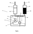
- Fig. 1 shows the dosing device 1 according to the invention, which consists of the dosing device 2 and a container 9 connected to the dosing device 2, a preparation 10 contained.
- the at least second container, which contains a second composition and can be coupled to the dosing device is in the Fig. 1 not shown.
- the dosing device 2 comprises an energy source 3, a control unit 4, a sensor unit 5 and a micropump 6, these components preferably being integrated in a housing.
- the micropump 6 is connected to the power source 3 via the control unit 4.
- the control unit 4 in turn is connected to the sensor unit 5, which passes the control signals for controlling the micropump 6 to the control unit 4.
- the micropump 6 has a pressure line 7 and a suction line 8, the suction line 8 being connected to the container 9 containing the preparation 10.
- the micropump 6 thus conveys the flowable preparation 10 via the suction line 8 from the container 9 into the pressure line 7 from where the preparation 10 is delivered to the surroundings of the metering device 1.
- the pressure line 7 may in particular be such, e.g. by choosing a suitable diameter, be configured to counteract gelling of the dispensed preparation.
- the container 9 may have a pressure compensation valve 11 which effects a pressure equalization between the environment and the interior of the container 9 when the micropump 6 pumps preparation 10 out of the container 9.
- the micropump 6 can be controlled by the control unit 4 in such a way that the conveying direction of the micropump 6 is reversed and preparation still present in the micropump 6 and the lines 7 and 8 are returned to the container 9.
- This backwashing can be particularly advantageous if the preparation 10, for example, for thickening and thus for bonding the lines 7 or 8 tends.
- Fig. 2 shows a further embodiment of the Fig. 1 known metering device, in which the container 9 is connected on the pressure side with the micropump 6.
- the micro-pump 6 builds up a pressure in the container 9 by pumping ambient air into the container 9, so that the preparation is displaced from the container 9.
- a valve 11 may be provided that releases the preparation 10 from the container 9 only when a defined pressure in the container 9 is reached. This can be particularly advantageous if no dropwise metering, but a defined spray or spray similar dosage should be made.
- the at least second container, which contains a second composition and can be coupled to the dosing device is in the Fig. 2 not shown.
- a check valve 11a may be arranged between the micropump 6 and the container 9 in the pressure line 7, which prevents the pressure built up in the container 9 from escaping through the pressure line 7 when the micropump 6 is at a standstill.
- Figure 3 shows that off Fig.1 known metering device 2, in which a two-chamber container, which is formed from the containers 9 and 13, is connected to the suction line 8 of the micropump 6.
- the containers 9 and 13 each contain mutually different compositions 10 and 14.
- the containers 9 and 13 may each have pressure equalizing valves 11,12.
- the bottom-side discharge openings of the containers 9 and 13 are connected to the suction line 8 and the micropump 6 such that the preparations 10 and 14 are pumped in defined proportions to each other through the suction line 8.
- the incompatibility of two preparations may be due to an exetherme reaction, thickening, flocculation, pH change, color change or the like, for example.
- a third container may be provided which contains a flushing fluid that cleans the lines 7, 8 and the micropump 6 of at least one of the preparations 10, 14.
- a flushing fluid that cleans the lines 7, 8 and the micropump 6 of at least one of the preparations 10, 14.
- Figure 4 shows a training of Figure 3 Known dosing 1.
- the leading to the bottom-side discharge openings of the container 9 and 13 pressure lines 8 in this case each have a passive valve 15 and 16, which allow a defined adjustment of the dosing of the preparations 10 and 14 from the containers 9 and 13.
- the valves 15 and 16 may also be designed as temperature-sensitive bimetallic valves which open or close upon reaching a defined temperature.
- the valves 15 and 16 can be selected from bimetal valves which are different from one another, so that, for example, when a defined temperature is reached, only one preparation can be conveyed out of the container 9 or 13 by the micropump 6.
- control unit 4 by processing the signals from the sensor unit 5 alone controls the micropump 6.
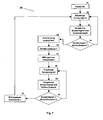
- the basic control algorithm 20 is in Fig. 6 reflected in the form of a flowchart.
- the control algorithm 20 is activated as soon as the dosing device 2 is switched on.
- the control unit 4 receives the signals of the sensor unit 5.
- the received sensor signal is compared with a threshold value stored in the control unit 4.
- step 24 it is checked by means of a selection condition whether the sensor signal and the threshold value are in a defined relationship to one another. If the condition is fulfilled, the micropump 6 is subsequently activated by the process step 25. If the condition is not fulfilled, further sensor signals according to process step 22 are received and evaluated by the control unit.
- the micropump 6 remains in an activated state until a sensor signal is present which causes a switch-off of the micropump when compared with a threshold value stored in the control unit 4. According to this procedure, preparation is pumped out of the containers as long as the sensor signal moves between two predefined threshold values for switching on or off the micropump 6.
- Threshold 1 Threshold 2 Dishwasher / washing machine temperature temperature temperature pH pH temperature pH pH temperature Time PH Time conductivity Time cloudiness Time
- valves 15 and 16 as components to be actively controlled by the control unit 4.
- the mixing ratio of the two preparations 10 and 14 can be influenced so active and time-varying.
- each of the containers 9 and 13 is coupled to a micropump 6 and 19 to be controlled individually by the control unit 4.
- the corresponding control algorithm is in Fig. 8 resist given.
- Fig. 9 shows the off Fig. 1 known metering device, in which on the container 9, an RFID label 42 is arranged, which is adapted to identify the size and the content 10 of the container 9.
- the sensor unit 5 comprises an RFID receiving unit which can read the information of the RFID label 42 arranged on the container 9. This information is sent as a control signal to the control unit 4, to a matched to the contents of the container 9 dosage of the preparation 10 to cause.
- the control signals caused by the RFID tag 42 can be used to select a metering program stored in the control unit.
- RFID tag 42 As an alternative to the RFID tag 42, those skilled in the art may also provide other means for automatically identifying the container 9 and its contents 10 through the metering device.
- an additional dispensing device 43 may be provided at the pressure-side opening of the pressure line 7.
- This dispensing device 43 effects a distribution of the preparation deviating from the dropwise delivery into the surroundings of the dosing device 1.
- This may be, for example, a jet-like or spray-like delivery of the preparation or a delivery based on evaporation or diffusion.
- the dispensing device 43 can be designed, for example, as a nozzle, atomizer, distributor plate or porous surface.
- the dispensing device can be designed such that it counteracts gelling of the released preparations.
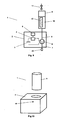
- Fig. 10 shows those from the Fig.1-5 and Fig. 9 known dosing in a perspective view.
- the dosing device 2 has an interface, by means of which the container 9 can be coupled to the dosing device 2.
- this interface can be as in Fig. 10 shown to be formed as an opening into which the container 9 is inserted.
- the dosing device 2 may have a display 44.
Description
Die Erfindung betrifft eine Dosiervorrichtung für fließfähige Zusammensetzungen, insbesondere Zusammensetzungen, die Wasch-, Reinigungsmittel und/oder Duftstoffe enthalten. Ferner betrifft die Erfindung Behälter zur Verwendung in der erfindungsgemäßen Dosiervorrichtung sowie ein Verfahren zum Betrieb der Dosiervorrichtung.The invention relates to a metering device for flowable compositions, in particular compositions containing detergents, cleaners and / or fragrances. Furthermore, the invention relates to containers for use in the metering device according to the invention and to a method for operating the metering device.
Die genaue und bedarfsgerechte Dosierung von fließfähigen Zusammensetzungen ist für eine Vielzahl von Anwendungsgebieten von Relevanz.The precise and appropriate dosage of flowable compositions is relevant for a variety of applications.
Insbesondere im Haushaltsbereich erfährt die Dosierung fließfähiger Substanzen eine steigende Bedeutung, was voranging in der exakten und bedarfsgesteurten Dosierung der entsprechenden Wirkstoffe begründet ist, wodurch zum einen die Umwelt durch Ressourcenschonung und Vermeidung von Fehl- und Überdosierungen geschont wird, zum anderen die Effizienz der so dosierten Wirkstoffe optimiert wird.Especially in the household sector, the dosage of flowable substances is of increasing importance, which is primarily based on the exact and needs-controlled dosage of the corresponding active ingredients, which on the one hand the environment is conserved by resource conservation and prevention of overdose and overdoses, on the other hand, the efficiency of dosed so Active ingredients is optimized.
Das Dokument
Reinigungsmittel für Geschirrspülmaschinen werden heute häufig in Form von Spülmitteltabletten verwendet. Obwohl die Anwendung und Dosierung für den Anwender vergleichsweise einfach und konvenient ist, erfolgt die Wirkstofffreisetzung aus den Tabletten jedoch nicht optimiert hinsichtlich der Spül- und Trocknungszyklen der jeweiligen Spülmaschine.Detergents for dishwashers are often used today in the form of detergent tablets. Although the application and dosage for the user is relatively simple and convenient, the drug release from the tablets is not optimized in terms of rinsing and drying cycles of the respective dishwasher.
Dosiervorrichtungen zur Abgabe von Reinigungsmitteln während der Spülzyklen einer Geschirrspülmaschine sind beispielsweise aus
Die Abgabe von Reinigungsmitteln wird hierbei durch ein Bimetall gesteuert, dass bei Erreichen einer vorbestimmten Temperatur einen Federmechanismus auslöst, der die Freigabe von Reinigungsmitteln in die Geschirrspülmaschine bewirkt.The dispensing of cleaning agents is controlled by a bimetal that triggers a spring mechanism upon reaching a predetermined temperature, which causes the release of cleaning agents in the dishwasher.
Ein wesentlicher Nachteil dieser Dosiervorrichtung ist ihr komplexer mechanischer Aufbau, wodurch die Kosten für ihre Herstellung hoch sind. Ferner kann der Freisetzungsmechanismus nur durch das Überschreiten bzw. Unterschreiten definierter Temperaturen in der Spülmaschine ausgelöst werden. Eine Möglichkeit, andere Parameter zur Auslösung der Reinigungsmittelfreisetzung heranzuziehen besteht hierbei nicht.A major disadvantage of this metering device is its complex mechanical structure, whereby the cost of their production are high. Furthermore, the release mechanism can only be triggered by exceeding or falling below defined temperatures in the dishwasher. One way to use other parameters to trigger the release of detergent does not exist here.
Des Weiteren ist die aus
Waschmittel werden heute üblicherweise über eine Dosierschublade der Waschmaschine in die mit Wäsche befüllten Trommel dosiert. Das Dosieren erfolgt durch Ausspülen der Dosierschublade mit Wasser, wodurch das Waschmittel aufgelöst bzw. mitgerissen und in die Wäschetrommel geleitet wird. Die Dosierschublade kann drei Kammern aufweisen, wobei eine für die Aufnahme eines Waschmittels für den Vorwaschgang, eine zur Aufnahme eines Waschmittels für den Hauptwaschgang und ein eine zur Aufnahme eines Weichspülers ausgebildet ist.Detergents are now usually dosed via a metering drawer of the washing machine in the drum filled with laundry. The dosing is done by rinsing the dosing drawer with water, whereby the detergent is dissolved or entrained and fed into the laundry drum. The metering drawer may have three chambers, one for receiving a detergent for the pre-wash, one for receiving a detergent for the main wash and one for receiving a softener.
Ein Problem dieser Dosierschubladen besteht darin, dass die Dosierung des Waschmittels aus der Schublade nur bedingt gesteuert werden kann. Üblicher weise wird unmittelbar bei Beginn eines Waschgangs durch Spülen der Dosierschublade mit Wasser die gesamte in der entsprechenden Kammer befindlichen Waschmittelmenge in die Waschtrommel eingetragen. Eine exakte, zeitlich variante Dosierung von Waschmittel innerhalb eines Waschgangs ist somit nicht möglich.A problem with these dosing drawers is that the dosage of the detergent from the drawer can only be controlled to a limited extent. The usual way is immediately at the beginning of a wash cycle by rinsing the dosing drawer with water the whole in the corresponding chamber registered detergent quantity in the washing drum. An exact, time-varying dosage of detergent within a wash cycle is thus not possible.
Des Weiteren sind zur Dosierung von Waschmitteln sog. Dosierkugeln bekannt, die mit einer definierten Waschmittelmenge befüllbar sind und direkt in die Waschtrommel mit der zu reinigenden Wäsche gegeben werden. Auch hier besteht der Nachteil, dass eine gesteuerte Waschmittelfreisetzung nicht erfolgt.Furthermore, so-called metering balls are known for metering detergents which can be filled with a defined amount of detergent and are added directly into the washing drum with the laundry to be cleaned. Again, there is the disadvantage that a controlled release of detergent does not occur.
Die Dosierung von Reinigungs- und Duftzusammensetzungen im WC-Bereich wird derzeit vorrangig durch sog. WC-Spüler realisiert. Hierbei handelt es sich um Ein- oder Mehrkammerbehältnisse, die derart in das WC-Becken gehangen werden, dass beim Spülvorgang des WC-Beckens mit Wasser eine Wirkstoffabgabe aus dem WC-Spüler in das Toilettenbecken erfolgt.The dosage of cleaning and fragrance compositions in the toilet area is currently primarily realized by so-called toilet flushing. These are single or multi-chamber containers that are hung in the toilet bowl so that when flushing the toilet bowl with water, a release of active ingredient from the toilet bowl into the toilet bowl.
Derartige Vorrichtungen sind beispielsweise aus
Ein wesentlicher Nachteil dieser WC-Spüler ist, dass die Dosierung im Wesentlichen von den jeweiligen lokalen Strömungsbedingungen im Toilettenbecken während des Spülvorgangs abhängt. Die Strömungsbedingungen können jedoch in Abhängigkeit vom Toilettentyp und der Positionierung des WC-Spülers in bzw. am Toilettenbecken sehr unterschiedlich sein. So kann es beispielsweise vorkommen, dass bei einigen Toilettentypen keine Wirkstofffreisetzung aus dem WC-Spüler erfolgt, da der WC-Spüler beim Spülvorgang nicht oder nicht hinreichend mit Wasser überströmt wird und der Dosiermechanismus des WC-Spülers somit nicht ausgelöst wird.A major disadvantage of these toilet flushers is that the dosage depends essentially on the particular local flow conditions in the toilet bowl during the flushing process. However, the flow conditions may vary greatly depending on the type of toilet and the positioning of the toilet bowl in or on the toilet bowl. So it may happen, for example, that in some types of toilet no drug release from the toilet rinse takes place because the toilet bowl is not or not sufficiently covered with water during flushing and thus the dosing of the toilet rinser is not triggered.
Auch falls ein WC-Spüler verwendungsgemäß von Spülwasser überströmt wird, so ist dies in so weit von Nachteil, als das es zu einer Störung der vom Toilettenhersteller vorgesehenen Wasserführung kommt, wodurch die Spülleistung einer Toilette spürbar reduziert werden kann.Even if a toilet-rinse is overflowed according to use of rinse water, so this is so far from disadvantage, as it is a disturbance of the Toilet manufacturer provided water supply, whereby the flushing power of a toilet can be significantly reduced.
Es wäre somit wünschenswert über eine Dosiervorrichtung zur Freisetzung von Wirkstoffen in ein Toilettenbecken zu verfügen, die eine vom Spülvorgang der Toilette unabhängige Dosierung von Wirkstoffen in das Toilettenbecken realisiert.It would therefore be desirable to have a metering device for releasing active ingredients in a toilet bowl, which realizes an independent of the flushing of the toilet dosage of active ingredients in the toilet bowl.
Ferner wäre es wünschenswert, wenn eine Wirkstofffreisetzung nicht nur nach Betätigung der Spülung erfolgen würde. Beispielsweise wäre es vorteilhaft, unmittelbar vor Benutzung der Toilette Duftstoffe oder Schaumbildner in das Toilettenbecken zu dosieren, um der mögliche Freisetzung von unangenehmen Geruchsstoffen während der Benutzung der Toilette präventiv entgegen zu wirken.Further, it would be desirable if drug release did not occur only after actuation of the rinse. For example, it would be advantageous to dose perfumes or foaming agents into the toilet bowl immediately prior to use of the toilet in order to preventively prevent the possible release of unpleasant odors during use of the toilet.
Derzeit ist es nicht möglich, eine Dosierung in den eingangs geschilderten Anwendungsfällen durch eine Dosiervorrichtung zu realisieren, so dass es derzeit noch notwendig ist, auf den jeweiligen Anwendungsfall hin zugeschnittene Dosiervorrichtungen zu verwenden.At present, it is not possible to implement a metering in the initially described applications by means of a metering device, so that at present it is still necessary to use metering devices tailored to the respective application.
Ferner weisen die beschriebenen Dosiervorrichtungen teilweise große Bauvolumen auf, was häufig aus ästhetischen Gründen als nachteilig empfunden wird und auch in funktioneller Hinsicht häufig Probleme bereitet, da beispielsweise der nutzbare Raum in einer Geschirrspülmaschine oder in einem Toilettenbecken verringert wird.Furthermore, the dosing devices described in some cases have large volumes, which is often perceived as disadvantageous for aesthetic reasons and also often presents problems from a functional point of view since, for example, the usable space in a dishwasher or in a toilet bowl is reduced.
Des Weiteren ist bekannt, dass viele Zubereitungen, insbesondere Wasch- und Reinigungszubereitungen, Tenside und zwar sowohl anionische als auch nichtionische Tenside und vor allem Tensidmischungen enthalten, die bei der Wiederauflösung in Wasser zur Ausbildung von Gelphasen neigen. Bereits bei Tensidgehalten von 15 Gew.-% und darüber, bezogen auf das Mittel, kann es bei der Wiederauflösung der Mittel in Wasser zu unerwünschten und löseverzögernden Vergelungen kommen.Furthermore, it is known that many preparations, in particular washing and cleaning preparations, contain surfactants both anionic and nonionic surfactants and especially surfactant mixtures which tend to form gel phases when redissolved in water. Already at surfactant contents of 15 wt .-% and above, based on the agent, it may come in the re-dissolution of the agent in water to undesirable and dissolution-delaying gelling.
Insbesondere durch eine einmalige, schwallartige Dosierung, wie sie heute weitestgehend z.B. durch Wasch-/ oder Reinigungstabletten üblich ist, kann es passieren, dass bei der Zufuhr derartige Tensidzubereitungen beispielsweise während eines Reinigungszyklus einer Spülmaschine, die Zubereitungen unmittelbar nach der Dosierung in den Spülmaschineninnenraum und dem Kontakt mit Wasser von Gelschichten überzogen werden, die dann eine rasche Auflösung auch der von der Gelschicht eingeschlossenen Zubereitung verhindern. Dieser Effekt ist umso ausgeprägter, je größer die Dosiermenge ist, die einmalig schwallartig abgegeben wird und je kälter das Wasser ist, in dem die Zubereitung aufgelöst werden soll.In particular, by a one-time, surge-like dosage, as today largely as. is common by washing or cleaning tablets, it may happen that during the supply of such surfactant preparations, for example, during a cleaning cycle of a dishwasher, the preparations are coated immediately after dosing in the dishwasher interior and the contact with water of gel layers, then a rapid resolution Also prevent the enclosed by the gel layer preparation. This effect is all the more pronounced, the larger the dosing amount is, which is delivered once gushing and the colder the water is in which the preparation is to be dissolved.
Dies kann dazu führen, dass am Ende des Spülprogramms vergelte Zubereitungsreste in der Spülmaschine oder auf dem Geschirr zurückbleiben und eventuell nicht genügend Tensid während des Spülprogramms freigesetzt wird, um eine befriedigende Reinigungsleistung der Zubereitung zu bewirken. Diese nachteiligen Effekte bei der Dosierung von zur Vergelung neigenden Tensidzubereitungen sind nicht auf den Bereich der Geschirrreinigung beschränkt, sondern sind ebenfalls im Bereich der Textilreinigung und WC-Pflege bekannt.This may result in retarded cooking residues remaining in the dishwasher or on the dishes at the end of the wash program, and insufficient surfactant may be released during the wash cycle to provide satisfactory cleaning performance of the formulation. These detrimental effects in the metering of gel-prone surfactant formulations are not limited to the field of dishwashing, but are also known in the textile cleaning and toilet care art.
Es ist daher eine Dosiervorrichtung wünschenswert, die zur Vergelung neigende Tensidgemische derart freisetzt, dass eine Vergelung weitestgehend unterbunden oder zumindest deutlich reduziert wird.It is therefore desirable that a dosing device releases the surfactant mixtures which tend to gel in such a way that gelling is largely prevented or at least significantly reduced.
Es ist daher die Aufgabe der Erfindung die Nachteile der Dosiervorrichtungen der eingangs geschilderten Art zu verhindern und eine Dosiervorrichtung bereitzustellen, die eine exakte Dosierung von fließfähigen Zusammensetzungen beim Eintreten definierter mechanischer, elektrischer, physikalischer und/ oder chemischer Bedingungen bei realisiert.It is therefore the object of the invention to prevent the disadvantages of the metering devices of the type described above and to provide a metering device which implements an exact metering of flowable compositions upon the occurrence of defined mechanical, electrical, physical and / or chemical conditions.
Eine weitere Aufgabe der Erfindung besteht des Weiteren darin, eine Dosiervorrichtung bereitzustellen, die zur Vergelung neigende Tensidgemische derart freisetzt, dass die Gefahr einer Vergelung zumindest deutlich reduziert wird.It is a further object of the invention to provide a metering device which liberates surfactant mixtures tending to gel in such a way that the risk of gelation is at least significantly reduced.
Die Aufgabe wird dadurch gelöst, dass eine Dosiervorrichtung für fließfähige Zubereitungen ein Dosiergerät mit einer Energiequelle, einer Steuereinheit und einer Sensoreinheit, sowie wenigstens einen ersten Behälter, der eine erste Zubereitung beinhaltet und der mit dem Dosiergerät koppelbar ist, umfasst, wobei das Dosiergerät eine durch die Steuereinheit steuerbare Mikropumpe mit einer spezifischen Fördermenge von weniger als 500 [1/min] umfasst, und wobei wenigstens ein zweiter Behälter, der eine zweite Zusammensetzung beinhaltet, mit dem Dosiergerät koppelbar ist.The object is achieved in that a metering device for flowable preparations comprises a metering device with an energy source, a control unit and a sensor unit, and at least a first container which includes a first preparation and which can be coupled to the metering device, wherein the metering device by the control unit comprises a controllable micropump having a specific delivery rate of less than 500 [1 / min], and wherein at least a second container containing a second composition is coupleable to the dosing device.
Koppelbar bedeutet in diesem Zusammenhang, dass der Behälter derart mit dem Dosiergerät verbunden werden kann, dass das Innere des Behälters mit der Mikropumpe kommunizierend verbunden und eine leckagefreie Entnahme von Zubereitung aus dem Behälter realisiert ist.Coupling in this context means that the container can be connected to the dosing device in such a way that the interior of the container communicates with the micropump and a leakage-free removal of preparation from the container is realized.
Ein wesentlicher Vorteil der Erfindung ist in der Trennung der Dosiervorrichtung in ein Dosiergerät und in ein mit dem Dosiergerät koppelbaren Behälter zu sehen, wodurch das Dosiergerät flexibel für die unterschiedlichsten Anwendungsfälle verwendet werden kann.A significant advantage of the invention is to be seen in the separation of the metering device in a metering device and in a coupled with the metering container, whereby the metering device can be used flexibly for a variety of applications.
Da die Dosiervorrichtung keine mechanische Steuerungselemente zur Produktfreisetzung verwendet, kann die Dosiervorrichtung derart minituriarisiert werden, dass sie auch in Applikationen, bei denen die Größe der Dosiervorrichtung kritisch ist, wie beispielsweise bei WC-Spülern oder Spülmaschinendosieren, eingesetzt werden kann.Since the metering device does not use mechanical control elements for product release, the metering device can be miniaturized in such a way that it can also be used in applications in which the size of the metering device is critical, such as in toilet bowls or dishwasher dosing.
In dem Dosiergerät ist die zum Betrieb der Dosiervorrichtung notwendige Energiequelle, eine Steuereinheit, eine Sensoreinheit sowie wenigstens eine Mikropumpe integriert. Vorzugsweise besteht das Dosiergerät aus einem spritzwassergeschütztem Gehäuse, dass das Eindringen von Spritzwasser, wie es beispielsweise bei der Verwendung der erfindungsgemäßen Dosiervorrichtung in einem Toilettenbecken oder einer Geschirrspülmaschine auftreten kann, in das Innere des Dosiergeräts verhindert.In the metering device, the energy source necessary for operating the metering device, a control unit, a sensor unit and at least one micropump are integrated. Preferably, the dosing device consists of a splash-proof housing that the penetration of water spray, such as it can occur, for example, when using the metering device according to the invention in a toilet bowl or a dishwasher, prevented in the interior of the metering device.
Um den Betrieb bei erhöhten Temperaturen, wie sie beispielsweise in einzelnen Waschzyklen einer Geschirrspülmaschine auftreten, zu gewährleisten, kann die Dosiervorrichtung aus Materialen geformt sein, die bis zu einer Temperatur von 120°C formstabil sind.In order to ensure operation at elevated temperatures, as occur, for example, in individual washing cycles of a dishwasher, the dosing device can be formed from materials which are dimensionally stable up to a temperature of 120 ° C.
Da die zu dosierenden Zubereitungen je nach beabsichtigtem Verwendungszweck einen pH-Wert zwischen 2 und 12 aufweisen können, sollten alle Komponenten der Dosiervorrichtung, die in Kontakt mit den Zubereitungen kommen, eine entsprechende Säure- und/oder Alkaliresistenz aufweisen. Ferner sollten die diese Komponenten durch eine geeignete Materialauswahl weitestgehend chemisch inert, beispielsweise gegen nichtionische Tenside, Enzyme und/oder Duftstoffe seinSince the preparations to be dosed may have a pH between 2 and 12, depending on the intended use, all components of the dosing device which come into contact with the preparations should have a corresponding acid and / or alkali resistance. Furthermore, these components should be largely chemically inert by a suitable choice of material, for example against nonionic surfactants, enzymes and / or fragrances
Besonders vorteilhaft ist es, die Energiequelle, die Steuereinheit, die Sensoreinheit und die Mikropumpe derart zu vergießen, dass das Dosiergerät im Wesentlichen wasserdicht, das Dosiergerät also auch bei vollständigem Umschluss mit Flüssigkeit funktionsfähig ist. Als Vergussmaterialien können beispielsweise mehrkomponentige Epoxyd-, und Acrylat-Vergußmassen wie Methacrylatester, Urethan-Metha und Cyanacrylate oder Zweikomponenten-Materialien mit Polyurethanen, Silikonen, Epoxydharzen verwendet werden.It is particularly advantageous to shed the energy source, the control unit, the sensor unit and the micropump in such a way that the metering device is substantially watertight, ie the metering device is able to function even when fully enclosed with liquid. As potting materials, for example, multicomponent epoxy, and acrylate potting compounds such as methacrylate esters, urethane-metha and cyanoacrylates or two-component materials can be used with polyurethanes, silicones, epoxy resins.
Die erfindungsgemäße Dosiervorrichtung kann beispielsweise als zur Dosierung von Reinigungsmitteln in Geschirrspülmaschinen oder Toilettenbecken, von Waschmitteln in Waschmaschinen oder Duftstoffen zur Raumluftverbesserung verwendet werden.The metering device according to the invention can be used, for example, for metering cleaning agents in dishwashers or toilet bowls, washing detergents in washing machines or fragrances for improved room air.
Eine Mikropumpe im Sinne dieser Anmeldung ist eine mikrosystemtechnische Fluidenergiemaschine zum Bewegen oder Fördern kleiner Mengen eines Fluids durch Wandlung einer mechanischen Antriebsleistung in eine Strömungsleistung.A micropump in the sense of this application is a microsystem fluid energy machine for moving or conveying small quantities of a fluid by converting a mechanical drive power into a flow rate.
Unter Fluiden werden im Folgenden Flüssigkeiten und Gase, sowie Mischungen daraus und mit Feststoffen verstanden.In the following, fluids are liquids and gases, as well as mixtures thereof and solids.
Die Fördermenge einer erfindungsgemäßen Mikropumpe beträgt üblicherweise zwischen 50 nl und 100 ml pro Minute, bevorzugt zwischen 250 nl und 30 ml pro Minute, besonders bevorzugt zwischen 500 nl und 5 ml pro Minute.The delivery rate of a micropump according to the invention is usually between 50 nl and 100 ml per minute, preferably between 250 nl and 30 ml per minute, more preferably between 500 nl and 5 ml per minute.
Bevorzugt weist die Mikropumpe ein Bauvolumen von unter 5 cm3, besonders bevorzugt von unter 3 cm3, insbesondere bevorzugt von unter 2 cm3 auf.The micropump preferably has a construction volume of less than 5 cm 3 , particularly preferably less than 3 cm 3 , particularly preferably less than 2 cm 3 .
Die spezifische Fördermenge einer Mikropumpe, gebildet aus dem Verhältnis von Fördermenge zum Bauvolumen einer Mikropumpe, beträgt üblicherweise weniger als 500 [1/min]. Bevorzugt liegt die spezifische Fördermenge zwischen 1 und 300, besonders bevorzugt zwischen 1,5 und 200, insbesondere bevorzugt zwischen 2 und 150, ganz besonders bevorzugt zwischen 2,5 und 100.The specific delivery rate of a micropump, formed from the ratio of delivery rate to the construction volume of a micropump, is usually less than 500 [1 / min]. The specific delivery rate is preferably between 1 and 300, more preferably between 1.5 and 200, particularly preferably between 2 and 150, with very particular preference between 2.5 and 100.
Durch diese Auswahl der spezifischen Fördermengen können insbesondere tensidhaltige Zubereitungen dosiert werden, ohne dass bei der Freisetzung eine Gefahr der Vergelung der Zubereitungen besteht.In particular surfactant-containing preparations can be metered by this selection of the specific delivery quantities, without the risk of gelation of the preparations during release.
Die Mikropumpe kann ausgewählt werden aus der Gruppe der Verdrängerpumpen, oszillatorischen Pumpen, Membranpumpen, Kolbenpumpen, rotatorischen Pumpen, dynamischen Pumpen, Zentrifugalpumpen, elektrohydrodynamische Pumpen, elektroosmotische Pumpen, magnetohydrodynamische Pumpen, Surface-Acoustic-Wave-Pumpen, Kapillarkraft-Pumpen, Electrowetting-Pumpen, thermokapillare Pumpen. Besonders vorteilhaft für die Dosierung von Wasch- und Reinigungsmitteln sowie von Duftstoffen sind Membranpumpen.The micropump can be selected from the group of positive displacement pumps, oscillatory pumps, diaphragm pumps, piston pumps, rotary pumps, dynamic pumps, centrifugal pumps, electrohydrodynamic pumps, electroosmotic pumps, magnetohydrodynamic pumps, surface acoustic wave pumps, capillary force pumps, electrowetting pumps , thermocapillary pumps. Particularly advantageous for the dosage of detergents and cleaners and fragrances are membrane pumps.
Membranpumpen bestehen üblicherweise aus einem Einlass- und einem Auslassventil in bzw. aus einer Pumpkammer, die teilweise aus einer Pumpmembran gebildet ist und einem Aktor.Diaphragm pumps usually consist of an inlet and an outlet valve in or out of a pumping chamber, which is partially formed of a pumping membrane and an actuator.
Der Aktor bewirkt bei geschlossenem Einlassventil eine Kompression der Pumpkammer durch mechanische Einwirkung auf die Pumpmembran, wodurch das in der Pumpkammer befindliche Fluid über das geöffnete Auslassventil aus der Pumpkammer gefördert wird.The actuator causes a compression of the pumping chamber by mechanically acting on the pump diaphragm with the inlet valve closed, whereby the fluid in the pumping chamber is conveyed out of the pumping chamber via the opened outlet valve.
Ist der Ausstoßvorgang abgeschlossen, wird das Auslassventil geschlossen und die Dekompression der Pumpkammer durch den Aktor bewirkt, wodurch das Fluid über nun das geöffnete Einlassventil in die Pumpkammer gesaugt wird.When the ejection operation is completed, the outlet valve is closed and the decompression of the pumping chamber is effected by the actuator, whereby the fluid is sucked into the pumping chamber via the opened inlet valve.
Es ist ersichtlich, dass durch eine geeignete Konfiguration und/oder Steuerung der Ventile und des Aktors, die Förderrichtung der Mikropumpe beeinflusst bzw. umgekehrt werden kann.It can be seen that by suitable configuration and / or control of the valves and the actuator, the conveying direction of the micropump can be influenced or reversed.
Der Aktor der Membranpumpe kann beispielsweise aus der Gruppe der elektromotorischen, piezokeramischen, bimetallischen, memometallischen, pneumatischen, peristaltischen, elektrostatischen, elektromagnetischen, thermischen Antriebseinheiten ausgewählt sein.The actuator of the diaphragm pump can be selected, for example, from the group of electromotive, piezoceramic, bimetallic, memometallic, pneumatic, peristaltic, electrostatic, electromagnetic, thermal drive units.
Die Ventile können als aktive oder passive Ventile ausgebildet sein. Bei den passiven Ventilen kann es sich insbesondere um Klappenventile, Membranventile oder No-Moving-Parts-Ventile handeln.The valves can be designed as active or passive valves. The passive valves may in particular be flapper valves, diaphragm valves or no-moving parts valves.
Je nach Anwendungsgebiet kann die druckseitige Abgabe der Zubereitung aus der Dosiervorrichtung tropfenweise, strahl- oder sprühartig, diffusiv oder durch Verdampfen erfolgen.Depending on the field of application, the pressure-side delivery of the preparation from the metering device may be dropwise, jet-like or spray-like, diffuse or by evaporation.
Insbesondere bei Zubereitungen, die dazu neigen bei längerer Lagerung Ablagerungen zu bilden, kann es vorteilhaft sein, den Zubereitung enthaltenen Behälter auf der Druckseite der Mikropumpe anzuordnen. In dieser Konfiguration wird lediglich ein Fluid frei von Ablagerungen bildenden Substanzen durch die Mikropumpe gefördert. Besonders vorteilhaft ist es in diesem Fall als Fluid Luft zu verwenden.In particular, in the case of preparations which tend to form deposits during prolonged storage, it may be advantageous to arrange containers containing the preparation on the pressure side of the micropump. In this configuration, only a fluid free of deposits forming substances is promoted by the micropump. It is particularly advantageous in this case to use air as the fluid.
Das Fluid wird unter Druck in den Behälter gepumpt. Der Behälter verfügt über ein Druckausgleichsventil, dass bei Überschreiten eines definierten Drucks in dem Behälter den Produktfluss aus dem Behälter freigibt.The fluid is pumped into the container under pressure. The container has a pressure compensation valve that releases the product flow from the container when a defined pressure in the container is exceeded.
Hierdurch wird es insbesondere möglich, das Dosiergerät für unterschiedlichste Zubereitungen zu verwenden, ohne die Funktionalität der Mikropumpe durch mögliche Ablagerungen oder Reaktionen zwischen zwei Zubereitungen zu gefährden.This makes it possible, in particular, to use the metering device for a wide variety of preparations without endangering the functionality of the micropump by possible deposits or reactions between two preparations.
Eine Steuereinheit im Sinne dieser Anmeldung ist eine Vorrichtung, die geeignet ist, das Transportieren von Material, Energie und/oder Information zu beeinflussen. Die Steuereinheit beeinflusst hierzu Wandler mit Hilfe von Informationen, die sie im Sinne des Steuerungsziels verarbeitet.A control unit in the sense of this application is a device which is suitable for influencing the transport of material, energy and / or information. For this purpose, the control unit influences transducers with the aid of information which it processes in the sense of the control target.
Bei den Wandlern kann es sich beispielsweise um Mikropumpen und/oder Ventile handeln.The transducers can be, for example, micropumps and / or valves.
Insbesondere kann es sich bei der Steuereinheit um einen programmierbaren Mikroprozessor handeln. In einer besonders bevorzugten Ausführungsform der Erfindung ist auf dem Mikroprozessor eine Mehrzahl von Dosierprogrammen gespeichert, die entsprechend dem an das Dosiergerät gekoppelten Behälter auswählbar und ausführbar sind.In particular, the control unit may be a programmable microprocessor. In a particularly preferred embodiment of the invention, a plurality of dosing programs are stored on the microprocessor, which can be selected and executed according to the container coupled to the dosing device.
Die Steuereinheit weist in einer bevorzugten Ausführungsform keine Verbindung zur möglicherweise vorhandenen Steuerung des Haushaltsgeräts auf. Es werden demnach keine Informationen, insbesondere elektrische oder elektromagnetischen Signale, direkt zwischen der Steuereinheit und der Steuerung des Haushaltsgeräts ausgetauscht.The control unit has, in a preferred embodiment, no connection to the possibly existing control of the household appliance. Accordingly, no information, in particular electrical or electromagnetic signals, is exchanged directly between the control unit and the control of the household appliance.
Zur Dosierung von insbesondere zur Vergelung neigenden Zubereitungen kann die Steuereinheit derart konfiguriert sein, dass einerseits die Dosierung in hinreichend kurzer Zeit erfolgt um ein gutes Reinigungsergebnis zu gewährleisten und andererseits die Zubereitung nicht so schnell dosiert, dass Vergelungen des Zubereitungsschwalls auftreten. Dies kann beispielsweise durch eine intervallartige Freisetzung realisiert sein, wobei die einzelnen Dosierungsintervalle so eingestellt sind, das sich die entsprechend dosierte Menge vollständig während eines Reiniungszyklus auflösen.For dosing preparations which are in particular prone to gelling, the control unit can be configured in such a way that on the one hand the dosing takes place in a sufficiently short time to ensure a good cleaning result and on the other hand the dosing of the preparation does not occur so quickly. This can be realized, for example, by an interval-like release, whereby the individual metering intervals are set in such a way that the corresponding metered amount dissolves completely during a cleaning cycle.
Die Sensoreinheit kann einen oder mehrere aktive und/oder passive Sensoren zur qualitativen und/oder quantitativen Erfassung mechanischer, elektrischer, physikalischer und/oder chemischer Größen umfassen, die als Steuersignale an die Steuereinheit geleitet werden.The sensor unit may comprise one or more active and / or passive sensors for the qualitative and / or quantitative detection of mechanical, electrical, physical and / or chemical variables, which are passed as control signals to the control unit.
Insbesondere können die Sensoren der Sensoreinheit aus der Gruppe der Zeitgeber, Infrarotsensoren, Helligkeitssensoren, Temperatursensoren, Bewegungssensoren, Dehnungssensoren, Drehzahlsensoren, Näherungssensoren, Durchflusssensoren, Farbsensoren, Gassensoren, Vibrationssensoren, Drucksensoren, Leitfähigkeitssensoren, Trübungssensoren, Schallwechseldrucksensoren, "Lab-on-a-Chip"-Sensoren, Kraftsensoren, Beschleunigungssensoren, Neigungssensoren, pH-Wert-Sensoren, Feuchtigkeitssensoren, Magnetfeldsensoren, RFID-Sensoren, Magnetfeldsensoren, Hall-Sensoren, Bio-Chips, Geruchssensoren, Schwefelwasserstoffsensoren und/oder MEMS-Sensoren ausgewählt sein.In particular, the sensors of the sensor unit from the group of timers, infrared sensors, brightness sensors, temperature sensors, motion sensors, strain sensors, speed sensors, proximity sensors, flow sensors, color sensors, gas sensors, vibration sensors, pressure sensors, conductivity sensors, turbidity sensors, sound pressure sensors, "lab-on-a-chip Sensors, force sensors, acceleration sensors, inclination sensors, pH sensors, humidity sensors, magnetic field sensors, RFID sensors, magnetic field sensors, Hall sensors, biochips, odor sensors, hydrogen sulfide sensors and / or MEMS sensors.
Die Sensoreinheit kann in ihrer einfachsten denkbaren Ausführungsform als ein Kipp-, Druck- oder Tastschalter ausgeführt sein.The sensor unit can be designed in its simplest possible embodiment as a tilt, push or push switch.
Insbesondere bei Zubereitungen deren Viskosität temperaturabhängig stark schwankt, ist es zur Volumen- bzw. Massenkontrolle der dosierten Zubereitungen von Vorteil, Durchflusssensoren in der Dosiervorrichtung vorzusehen. Geeignete Durchflusssensoren können aus der Gruppe der Blenden-Durchflusssensoren, magnetisch-induktiven Durchflussmessern, Massendurchflussmessung nach dem Coriolis-Verfahren, Wirbelzähler-Durchflussmessverfahren, Ultraschalldurchflussmessverfahren, Schwebekörperdurchflussmessung, Ringkolbendurchflussmessung, thermische Massendurchflussmessung oder Wirkdruckdurchflussmessung ausgewählt sein.Particularly in the case of preparations whose viscosity varies greatly depending on the temperature, it is advantageous for volume or mass control of the metered preparations to provide flow sensors in the metering device. Suitable flow sensors may be selected from the group of orifice flow rate sensors, electromagnetic flowmeters, Coriolis mass flow rate measurement, vortex flowmeter, ultrasonic flow rate measurement, variable area flow measurement, annular piston flow measurement, thermal mass flow measurement, or differential pressure flow measurement.
Es ist auch denkbar, dass in der Steuereinheit eine von der Temperatur abhängige Viskositätskurve wenigstens einer Zubereitung hinterlegt ist, wobei die Dosierung entsprechend der Temperatur und somit der Viskosität der Zubereitung durch die Steuereinheit angepasst wird.It is also conceivable for a temperature-dependent viscosity curve of at least one preparation to be deposited in the control unit, wherein the dosage is adjusted by the control unit according to the temperature and thus the viscosity of the preparation.
In einer weiteren Ausgestaltungsform der Erfindung ist eine Vorrichtung zur direkten Bestimmung der Viskosität der Zubereitung vorgesehen.In a further embodiment of the invention, an apparatus for direct determination of the viscosity of the preparation is provided.
Die vorab aufgeführten Alternativen zur Bestimmung der Dosiermenge bzw. der Viskosität einer Zubereitung dienen zur Erzeugung eines Steuersignals, dass durch die Steuereinheit derart zur Steuerung einer Mikropumpe verarbeitet wird, dass im wesentlichen eine konstante Dosierung einer Zubereitung bewirkt wird.The alternatives listed above for determining the metered quantity or the viscosity of a preparation are used to generate a control signal that is processed by the control unit in such a way for controlling a micropump that essentially a constant metering of a preparation is effected.
Im Sinne dieser Anmeldung wird als Energiequelle ein Bauelement der Dosiervorrichtung verstanden, welches zweckmäßig ist, eine zum autarken Betrieb der Dosiervorrichtung geeignete Energie bereit zu stellen.For the purposes of this application is understood as an energy source, a component of the metering device, which is expedient to provide a self-sufficient operation of the metering suitable energy.
Vorzugsweise stellt die Energiequelle elektrische Energie zur Verfügung. Bei der Energiequelle kann es sich beispielsweise um eine Batterie, ein Netzgerät, Solarzellen oder dergleichen handeln.Preferably, the energy source provides electrical energy. The energy source may be, for example, a battery, a power supply, solar cells or the like.
Besonders vorteilhaft ist es, die Energiequelle austauschbar auszuführen, zum Beispiel in Form einer auswechselbaren Batterie.It is particularly advantageous to make the energy source replaceable, for example in the form of a replaceable battery.
Unter einem Behälter im Sinne dieser Anmeldung wird ein Packmittel verstanden, das dazu geeignet ist, fließfähige Zubereitungen zu umhüllen oder zusammenzuhalten und das zur Abgabe der Zubereitung an ein Dosiergerät koppelbar ist. In der vorliegende Erfindung, ist wenigstens ein zweiter Behälter, der eine zweite Zusammensetzung beinhaltet, mit dem Dosiergerät koppelbar.For the purposes of this application, a container is understood to mean a packaging material which is suitable for enveloping or holding together flowable preparations and which can be coupled to a dosing device for dispensing the preparation. In the present invention, at least a second container containing a second composition is coupleable to the dosing device.
Bevorzugt beträgt das Volumenverhältnis gebildet aus dem Bauvolumen des Dosiergeräts und dem Füllvolumen des Behälters <1, besonders bevorzugt <0,1, insbesondere bevorzugt <0,05. Hierdurch wird erreicht, dass bei einem vorgegebenen Gesamtbauvolumen von Dosiergerät und Behälter, der überwiegende Anteil des Bauvolumens durch den Behälter und die darin enthaltene Zubereitung in Anspruch genommen wird.Preferably, the volume ratio formed from the overall volume of the metering device and the filling volume of the container <1, more preferably <0.1, particularly preferably <0.05. This ensures that, for a given total construction volume of metering device and container, the overwhelming portion of the construction volume is taken up by the container and the preparation contained therein.
Der Behälter weist üblicherweise ein Füllvolumen von <5.000 ml, Insbesondere <1.000 ml, bevorzugt <500ml, besonders bevorzugt <250 ml, ganz besonders bevorzugt < 50 ml auf.The container usually has a filling volume of <5,000 ml, in particular <1,000 ml, preferably <500 ml, more preferably <250 ml, most preferably <50 ml.
Die Erfindung ist insbesondere geeignet für formstabile Behältnisse wie Becher, Dosen, Kartuschen, Patronen, Flaschen, Kanister, Kannen, Schachteln, Trommeln oder Tuben, kann jedoch auch für flexible Behältnisse wie Beutel oder Säcke verwendet werden, insbesondere, wenn sie gemäß des bag-in-bottle-Prinzips verwendet werden.The invention is particularly suitable for dimensionally stable containers such as cups, cans, cartridges, cartridges, bottles, canisters, cans, boxes, drums or tubes, but can also be used for flexible containers such as bags or sacks, in particular if they are in accordance with the bag. be used in-bottle principle.
Insbesondere kann ein Behälter auch mehrere Kammern umfassen, die mit voneinander verschiedenen Zusammensetzungen befüllbar sind. Auch ist es denkbar, dass eine Behältermehrzahl zu einer Einheit, beispielsweise zu einer Patrone, angeordnet wird. In der vorliegende Erfindung, ist wenigstens ein zweiter Behälter, der eine zweite Zusammensetzung beinhaltet, mit dem Dosiergerät koppelbar.In particular, a container can also comprise a plurality of chambers which can be filled with different compositions from each other. It is too conceivable that a plurality of containers to a unit, for example, a cartridge is arranged. In the present invention, at least a second container containing a second composition is coupleable to the dosing device.
Beispiele für mögliche Kombinationen von Behältern bzw. Kammern mit den entsprechenden Zubereitungen sind für einige Anwendungsfälle in folgender Tabelle beispielhaft zusammengestellt.
In einer bevorzugten Ausführungsform der Erfindung, weist der Behälter ein RFID-Etikett auf, dass zumindest Informationen über den Inhalt des Behälters beinhaltet und das durch die Sensoreinheit auslesbar ist.In a preferred embodiment of the invention, the container has an RFID tag that contains at least information about the contents of the container and that can be read by the sensor unit.
Diese Informationen können verwendet werden, um ein in der Steuereinheit gespeichertes Dosierprogramm auszuwählen. Hierdurch kann sichergestellt werden, dass stets ein für eine bestimmte Zubereitung optimales Dosierprogramm verwendet wird. Es kann auch vorgesehen sein, dass bei nicht Vorhandensein eines RFID-Labels oder bei einem RFID-Label mit einer falschen oder fehlerhaften Kennung, keine Dosierung durch die Dosiervorrichtung erfolgt und statt dessen ein optisches oder akustisches Signal erzeugt wird, dass den Benutzer auf den vorliegenden Fehler hinweist.This information can be used to select a dosing program stored in the control unit. In this way it can be ensured that an optimal dosing program is always used for a particular preparation. It can also be provided that in the absence of an RFID label or an RFID label with a false or faulty identifier, no dosage is carried out by the metering device and instead an optical or acoustic signal is generated that the user to the present Error indicates.
Um einen Fehlgebrauch der Behälter auszuschließen, können die Behälter auch strukturelle Elemente aufweisen, die mit korrespondierenden Elementen des Dosiergeräts nach dem Schlüssel-Schloss-Prinzip zusammenwirken, so dass beispielsweise nur Behälter eines bestimmten Typs an das Dosiergerät koppelbar sind. Ferner ist es durch diese Ausgestaltung möglich, dass Informationen über den an das Dosiergerät gekoppelten Behälter an die Steuereinheit übertragen werden, wodurch eine auf den Inhalt des dementsprechenden Behälters abgestimmte Steuerung der Dosiervorrichtung erfolgen kann.In order to prevent misuse of the container, the containers may also have structural elements which cooperate with corresponding elements of the metering device according to the key-lock principle, so that, for example, only containers of a particular type can be coupled to the metering device. Furthermore, this configuration makes it possible for information about the container coupled to the dosing device to be transmitted to the control unit, as a result of which control of the dosing device coordinated with the contents of the corresponding container can take place.
Zubereitungen im Sinne dieser Anmeldungen sind fließfähige Zusammensetzungen, die wenigstens eine Substanz aus der Gruppe der Reinigungsmittel, Waschmittel und/oder Duftstoffe enthalten.Preparations within the meaning of these applications are flowable compositions containing at least one substance from the group of detergents, detergents and / or fragrances.
Bevorzugt beinhalten die Zubereitungen Tenside, besonders bevorzugt Niotenside wobei der Gewichtsanteil der Niotenside an der Gesamtzubereitung bevorzugt 0,5-40 Gew-%, besonders bevorzugt 1-15 Gew-%, insbesondere bevorzugt 5-10 Gew-% beträgt.The preparations preferably contain surfactants, particularly preferably nonionic surfactants, wherein the weight proportion of nonionic surfactants in the overall preparation is preferably 0.5-40% by weight, more preferably 1-15% by weight, particularly preferably 5-10% by weight.
- 11
- Dosiervorrichtungmetering
- 22
- Dosiergerätdosing
- 33
- Energiequelleenergy
- 44
- Steuereinheitcontrol unit
- 55
- Sensoreinheitsensor unit
- 66
- Mikropumpemicropump
- 77
- Druckleitungpressure line
- 88th
- Saugleitungsuction
- 99
- Behältercontainer
- 1010
- Zubereitungpreparation
- 1111
- DruckausgleichsventilPressure equalization valve
- 11a11a
- Rückschlagventilcheck valve
- 1212
- DruckausgleichsventilPressure equalization valve
- 1313
- Behältercontainer
- 1414
- Zubereitungpreparation
- 1515
- VentilValve
- 1616
- VentilValve
- 1717
- Druckleitungpressure line
- 1818
- Saugleitungsuction
- 1919
- Mikropumpemicropump
- 4242
- RFID-EtikettRFID tag
- 4343
- Abgabevorrichtung (Düse)Dispensing device (nozzle)
- 4444
- Anzeigedisplay
- Fig.1Fig.1
- Dosiervorrichtung mit Zubereitungsbehälter auf der Saugseite der MikropumpeDosing device with preparation container on the suction side of the micropump
- Fig.2Fig.2
- Dosiervorrichtung mit Zubereitungsbehälter auf der Druckseite der MikropumpeDosing device with preparation container on the pressure side of the micropump
- Fig.3Figure 3
- Dosiervorrichtung mit Zweikammer-Zubereitungsbehälter auf der Saugseite der MikropumpeDosing device with two-chamber preparation container on the suction side of the micropump
- Fig.4Figure 4
- Dosiervorrichtung mit passiv ventilgesteuertem Zweikammer-Zubereitungsbehälter auf der Saugseite der MikropumpeMetering device with passive valve-controlled two-chamber preparation container on the suction side of the micropump
- Fig. 4aFig. 4a
- Dosiervorrichtung mit aktiv ventilgesteuertem Zweikammer-Zubereitungsbehälter auf der Saugseite der MikropumpeDosing device with active valve-controlled two-chamber preparation container on the suction side of the micropump
- Fig.5Figure 5
- Dosiervorrichtung mit zwei Mikropumpen-verbundenen ZubereitungsbehältenDosing device with two micropump-connected preparation containers
- Fig.6Figure 6
- Ablaufplan für Steuerung der Dosiervorrichtung mit einer MikropumpeFlow chart for controlling the dosing device with a micropump
- Fig.7Figure 7
- Ablaufplan für Steuerung der Dosiervorrichtung mit einer Mikropumpe und Mehrkammer-ZubereitungsbehälterFlow chart for controlling the dosing device with a micropump and multi-chamber preparation container
- Fig.8Figure 8
- Ablaufplan für Steuerung der Dosiervorrichtung mit mehreren Mikropumpen und Mehrkammer-ZubereitungsbehälterFlow chart for controlling the dosing device with several micropumps and multi-chamber preparation container
- Fig.9Figure 9
- Dosiervorrichtung mit RFID-Etikett auf ZubereitungsbehälterDosing device with RFID label on preparation container
Das Dosiergerät 2 umfasst eine Energiequelle 3, eine Steuereinheit 4, eine Sensoreinheit 5 sowie eine Mikropumpe 6, wobei diese Komponenten vorzugsweise in einem Gehäuse integriert sind. Die Mikropumpe 6 ist über die Steuereinheit 4 mit der Energiequelle 3 verbunden. Die Steuereinheit 4 ihrerseits ist mit der Sensoreinheit 5 verbunden, welche die Steuersignale zur Steuerung der Mikropumpe 6 an die Steuereinheit 4 leitet.The
Die Mikropumpe 6 weist eine Druckleitung 7 und eine Saugleitung 8 auf, wobei die Saugleitung 8 mit dem die Zubereitung 10 beinhaltenden Behälter 9 verbunden ist. Die Mikropumpe 6 fördert so die fließfähige Zubereitung 10 über die Saugleitung 8 aus dem Behälter 9 in die Druckleitung 7 von wo aus die Zubereitung 10 an die Umgebung der Dosiervorrichtung 1 abgegeben wird. Die Druckleitung 7 kann insbesondere derart, z.B. durch Wahl eines geeigneten Durchmessers, konfiguriert sein, dass sie einer Vergelung der abgegebenen Zubereitung entgegenwirkt.The
Der Behälter 9 kann ein Druckausgleichsventil 11 aufweisen, welches einen Druckausgleich zwischen der Umgebung und dem Inneren des Behälters 9 bewirkt wenn die Mikropumpe 6 Zubereitung 10 aus dem Behälter 9 heraus pumpt.The
Die Mikropumpe 6 kann durch die Steuereinheit 4 derart angesteuert werden, das die Förderrichtung der Mikropumpe 6 umgekehrt wird und sich in der Mikropumpe 6 und den Leitungen 7 und 8 noch befindliche Zubereitung in den Behälter 9 zurückbefördert werden. Diese Rückspülung kann insbesondere dann von Vorteil sein, wenn die Zubereitung 10 beispielsweise zum Eindicken und somit zum Verkleben der Leitungen 7 oder 8 neigt.The
Zusätzlich kann zwischen der Mikropumpe 6 und dem Behälter 9 in der Druckleitung 7 ein Rückschlagventil 11a angeordnet sein, dass verhindert, dass der in dem Behälter 9 aufgebaute Druck bei Stillstand der Mikropumpe 6 durch die Druckleitung 7 entweicht.In addition, a
Die Behälter 9 und 13 können jeweils Druckausgleichsventile 11,12 aufweisen.The
Die bodenseitigen Ausgabeöffnungen der Behälter 9 und 13 sind derart mit der Saugleitung 8 und der Mikropumpe 6 verbunden, dass die Zubereitungen 10 und 14 in definierten Verhältnissen zueinander durch die Saugleitung 8 gepumpt werden. Hierzu kann es notwendig sein, die Strömungsverhältnisse in den zu den bodenseitigen Ausgabeöffnungen der Behälter 9 und 13 führenden Druckleitungen 8 entsprechend auszugestalten.The bottom-side discharge openings of the
Bei der Verwendung von mehr als zwei unterschiedlichen Zubereitungen 10 und 14 ist es von Vorteil, die Dosierung derart zu steuern, dass jeweils zwei miteinander verträgliche Zubereitungen nacheinander durch die Leitungen 7,8 und die Mikropumpe 6 gefördert werden.When using more than two
Die Unverträglichkeit zweier Zubereitungen kann beispielsweise durch eine exetherme Reaktion, Verdickung, Ausflockung, pH-Wert Veränderung, Farbumschlag oder dergleichen begründet sein.The incompatibility of two preparations may be due to an exetherme reaction, thickening, flocculation, pH change, color change or the like, for example.
Des weiteren kann ein dritter Behälter vorgesehen sein, der ein Spülfluid enthält, dass die Leitungen 7,8 und die Mikropumpe 6 von wenigstens einer der Zubereitungen 10,14 reinigt. Zur Spülung der Leitungen 7,8 und der Mikropumpe 6 kann auch Luft vorgesehen sein. Durch das Spülen der Leitungen 7,8 und der Mikropumpe 6 kann vermieden werden, dass Reste von nicht miteinander verträglichen Zubereitungen miteinander in Kontakt kommen.Furthermore, a third container may be provided which contains a flushing fluid that cleans the
Die Ventile 15 und 16 können auch als temperatursensitive Bimetallventile ausgebildet sein, die bei Erreichen einer definierten Temperatur öffnen bzw. schließen. Insbesondere können die Ventile 15 und 16 aus voneinander verschiedenen Bimetallventile ausgewählt sein, so dass beispielsweise bei erreichen eine definierten Temperatur nur eine Zubereitung durch die Mikropumpe 6 aus einem der Behälter 9 oder 13 gefördert werden kann.The
Den Dosiergeräten gemäß
Der prinzipielle Steuerungsalgorithmus 20 ist in
Der Steuerungsalgorithmus 20 wird aktiviert, sobald das Dosiergerät 2 eingeschaltet wird. Die Steuereinheit 4 empfängt in einem ersten Prozessschritt 22 die Signale der Sensoreinheit 5. In der Steuereinheit 4 wird das empfangene Sensorsignal mit einem in der Steuereinheit 4 gespeicherten Schwellenwert verglichen.The
Im nachfolgenden Prozessschritt 24 wird anhand einer Auswahlbedingung geprüft, ob das Sensorsignal und der Schwellenwert in einem definierten Verhältnis zueinander stehen. Wird die Bedingung erfüllt, wird nachfolgend durch den Prozessschritt 25 die Mikropumpe 6 aktiviert. Wird die Bedingung nicht erfüllt, werden weiterhin Sensorsignale gemäß Prozessschritt 22 durch die Steuereinheit empfangen und ausgewertet.In the
Wie aus den Prozessschritten 25-29 ersichtlich, bleibt die Mikropumpe 6 so lange in einem aktivierten Zustand, bis ein Sensorsignal vorliegt, dass beim Vergleich mit einem in der Steuereinheit 4 gespeicherten Schwellenwert ein ausschalten der Mikropumpe bewirkt. Gemäß dieser Verfahrensweise wird so lange Zubereitung aus den Behältern gepumpt, so lange sich das Sensorsignal zwischen zwei vordefinierten Schwellenwerten zum Ein- bzw. Ausschalten der Mikropumpe 6 bewegt.
Alternativ ist es jedoch auch denkbar, die eingangs beschriebene Steuerung derart abzuwandeln, dass eine einfache Trigger-Schaltung realisiert ist, bei der ein Einschalten der Mikropumpe gemäß Prozessschritt 25 die Abgabe einer definierten Menge an Zubereitung bewirkt um anschließend die Mikropumpe automatisch auszuschalten, ohne eine weitere sensorsignalbasierte Ausschaltbedingung für die Mikropumpe 6 zu benötigen.Alternatively, however, it is also conceivable to modify the control described above in such a way that a simple trigger circuit is realized in which switching on the micropump according to process step 25 causes the delivery of a defined amount of preparation in order to switch off the micropump automatically, without another one to require sensor signal-based switch-off condition for the
Wie in
Die dieser Ausführungsform zu Grunde liegende Steuerung ist in
Eine weitere Möglichkeit zur aktiven und zeitvarianten Beeinflussung der Mischungsverhältnisse zeigt
Die Sensoreinheit 5 umfasst ein RFID-Empfangseinheit, die die Informationen des auf dem Behälter 9 angeordneten RFID-Etikett 42 auslesen kann. Diese Informationen werden als Steuersignal an die Steuereinheit 4 geleitet, um eine auf den Inhalt des Behälters 9 abgestimmte Dosierung der Zubereitung 10 zu bewirken. Insbesondere können die durch das RFID-Etikett 42 bewirkten Steuersignale zur Auswahl eines in der Steuereinheit gespeicherten Dosierprogramms verwendet werden.The
Hierdurch ist es möglich, ein universelles Dosiergerät für eine Vielzahl von Dosieranwendungen bereitzustellen wie beilspielsweise die Dosierung von Zubereitungen in Spülmaschinen, Waschmaschinen, Trocknern, Toiletten oder Wohnräumen.This makes it possible to provide a universal dosing device for a variety of dosing applications such as the spielsweise the dosage of preparations in dishwashers, washing machines, dryers, toilets or living rooms.
Alternativ zum RFID-Etikett 42 kann der Fachmann auch andere Mittel vorsehen, die eine automatische Identifizierung des Behälters 9 und dessen Inhalt 10 durch das Dosiergerät bewirken.As an alternative to the
Ferner kann an der druckseitigen Öffnung der Druckleitung 7 eine zusätzliche Abgabevorrichtung 43 vorgesehen sein. Diese Abgabevorrichtung 43 bewirkt eine von der tropfenweise Abgabe abweichende Distribution der Zubereitung in die Umgebung der Dosiervorrichtung 1. Hierbei kann es sich beispielsweise um eine strahl- oder sprühnebelartige Abgabe der Zubereitung oder eine Abgabe basierend auf Verdampfung oder Diffusion handeln. Die Abgabevorrichtung 43 kann hierzu beispielsweise als Düse, Zerstäuber, Verteilerplatte oder poröse Oberfläche ausgebildet sein. Insbesondere kann die Abgabevorrichtung derart ausgebildet sein, dass sie einer Vergelung der freigesetzten Zubereitungen entgegenwirkt.Further, an
Claims (15)
- Dosing device (1) for flowable preparations, comprisinga) a dosing device (2) with an energy source (3), a control unit (4) and a sensor unit (5) as well asb) at least one first container (9) that contains a first preparation (10) and can be connected to the dosing device (2),
wherein
the dosing device (2) comprises a micro pump (6), which can be controlled by the control unit (4) and has a specific delivery rate of less than 500 [1/min],
characterized in that
at least one second container (13), which contains a second composition (14), can be connected to the dosing device (2). - Dosing apparatus according to one or more of the preceding claims, characterized in that the container (9) can be connected to the pressure side of the micro pump (6).
- Dosing apparatus according to one or more of the preceding claims, characterized in that the container (9) can be connected to the intake side on the micro pump (6).
- Dosing apparatus according to one or more of the preceding claims, characterized in that a valve (15, 16) is arranged between the container (9, 13) and the micro pump (6).
- Dosing apparatus according to one or more of the preceding claims, characterized in that the valve (15, 16) is actively controllable by the control unit (4).
- Dosing apparatus according to one or more of the preceding claims, characterized in that the dispensing of the preparation (10, 14) is triggered by a first micro pump (6), which can be connected to the first container (9), and a second micro pump (19), which can be connected to the second container (13).
- Dosing apparatus according to one or more of the preceding claims, characterized in that the container (9) comprises an RFID label (42), which includes at least information about the content of the container (9) and which can be read out by the sensor unit (5).
- Dosing apparatus according to one or more of the preceding claims, characterized in that the dosing device (2) is embodied at least with spray water protection.
- Dosing apparatus according to one or more of the preceding claims, characterized in that the energy source (3), the control unit (4), the sensor unit (5) and the micro pump (7, 19) are cast, so that the dosing device (2) is waterproof.
- Dosing apparatus according to one or more of the preceding claims, characterized in that the control unit (4) is a programmable microcontroller.
- Dosing apparatus according to one or more of the preceding claims, characterized in that a plurality of dosing programs is stored on the microcontroller and can be selected and executed in accordance with the container connected to the dosing device.
- Dosing apparatus according to one or more of the preceding claims, characterized in that the dosing apparatus also comprises a coupling device (7, 8) for accommodating at least one first container (9) that contains a first preparation (10).
- Method for controlling the dosing apparatus according to claim 1, characterized in that a dosing apparatus according to claim 1 is used, with the following steps:a) sensor signals are received, wherein the sensor signals contain at least information about the content of at least one container (9, 13) and/or information representing at least one physical, chemical or mechanical parameter,b) the sensor signals are compared with threshold values,c) a control signal is generated when a condition defined by comparing the sensor signals with the threshold values is met.
- Method for controlling the dosing apparatus according to claim 13, characterized in that the condition defined by comparing the sensor signals with the threshold values is selected for generating a control signal according to the content of at least one container (9, 13).
- Use of the dosing apparatus according to claim 1 for dosing flowable preparations in dishwashing machines, washing machines, toilet bowls, for room scenting or the like.
Priority Applications (1)
| Application Number | Priority Date | Filing Date | Title |
|---|---|---|---|
| PL07711871T PL2024548T3 (en) | 2006-06-07 | 2007-03-09 | Metering apparatus for flowable compositions |
Applications Claiming Priority (2)
| Application Number | Priority Date | Filing Date | Title |
|---|---|---|---|
| DE102006026800A DE102006026800A1 (en) | 2006-06-07 | 2006-06-07 | Dosing device for flowable compositions |
| PCT/EP2007/002059 WO2007140830A1 (en) | 2006-06-07 | 2007-03-09 | Metering apparatus for flowable compositions |
Publications (2)
| Publication Number | Publication Date |
|---|---|
| EP2024548A1 EP2024548A1 (en) | 2009-02-18 |
| EP2024548B1 true EP2024548B1 (en) | 2015-11-04 |
Family
ID=38120329
Family Applications (1)
| Application Number | Title | Priority Date | Filing Date |
|---|---|---|---|
| EP07711871.9A Revoked EP2024548B1 (en) | 2006-06-07 | 2007-03-09 | Metering apparatus for flowable compositions |
Country Status (8)
| Country | Link |
|---|---|
| US (1) | US20090194562A1 (en) |
| EP (1) | EP2024548B1 (en) |
| JP (1) | JP2009540273A (en) |
| DE (1) | DE102006026800A1 (en) |
| ES (1) | ES2555754T3 (en) |
| HU (1) | HUE028606T2 (en) |
| PL (1) | PL2024548T3 (en) |
| WO (1) | WO2007140830A1 (en) |
Families Citing this family (49)
| Publication number | Priority date | Publication date | Assignee | Title |
|---|---|---|---|---|
| DE102007014425A1 (en) * | 2007-03-22 | 2008-09-25 | Henkel Ag & Co. Kgaa | Mobile dosing system for dispensing flowable or spreadable preparations |
| KR101481508B1 (en) * | 2007-06-13 | 2015-01-13 | 엘지전자 주식회사 | Washing machine and method thereof |
| DE102007040328A1 (en) * | 2007-08-24 | 2009-02-26 | Henkel Ag & Co. Kgaa | Toilet freshener with directed release of active ingredient |
| DE102007040327A1 (en) * | 2007-08-24 | 2009-02-26 | Henkel Ag & Co. Kgaa | Toilet freshener with time-delayed release of active ingredient |
| DE102007040325B4 (en) * | 2007-08-24 | 2015-11-26 | Henkel Ag & Co. Kgaa | Toilet washer with electro-mechanically induced drug release |
| DE202007018952U1 (en) * | 2007-08-24 | 2009-11-26 | Henkel Ag & Co. Kgaa | Toilet freshener with adjustable drug delivery |
| DE102007040322B4 (en) * | 2007-08-24 | 2013-07-11 | Henkel Ag & Co. Kgaa | Toilet freshener with defined amount of active ingredient |
| DE102007040329A1 (en) * | 2007-08-24 | 2009-02-26 | Henkel Ag & Co. Kgaa | Toilet freshener with low-viscosity active substance |
| US20090090401A1 (en) * | 2007-10-05 | 2009-04-09 | Whirlpool Corporation | Appliance with Multiple Source Wash Aid Pump |
| DE102008007429A1 (en) * | 2008-02-01 | 2009-08-13 | Lothar Ernst Wilhelm Weber | Device for washing or cleaning objects |
| DE102008033237A1 (en) * | 2008-07-15 | 2010-01-21 | Henkel Ag & Co. Kgaa | Adapter for coupling a dosing system with a water-carrying pipe |
| DE102008036586A1 (en) | 2008-08-06 | 2010-02-11 | Henkel Ag & Co. Kgaa | Appliance |
| PL2334877T3 (en) * | 2009-02-24 | 2018-01-31 | Henkel Ag & Co Kgaa | Method for operating a wc rinser |
| EP2334876B1 (en) | 2009-02-24 | 2013-01-02 | Henkel AG & Co. KGaA | WC rinser |
| NL2003756C2 (en) * | 2009-11-04 | 2011-05-10 | Ecoplay Int Bv | DOSING DEVICE, A GRAY WATER SYSTEM PROVIDED THEREOF AND A METHOD OF USE THEREOF |
| DE102010027994A1 (en) * | 2010-04-20 | 2011-10-20 | Henkel Ag & Co. Kgaa | Dosing system for releasing at least three different preparations during a washing program of a washing machine |
| DE102010027991A1 (en) * | 2010-04-20 | 2011-10-20 | Henkel Ag & Co. Kgaa | Dosing system for use in connection with a water-conducting household appliance such as a washing machine, dishwasher, clothes dryer or the like |
| DE102010027992A1 (en) * | 2010-04-20 | 2011-10-20 | Henkel Ag & Co. Kgaa | Dosing system for releasing at least three different preparations during a washing program of a washing machine |
| US8833605B2 (en) | 2010-07-20 | 2014-09-16 | Ecolab Usa Inc. | Product delivery and monitoring system |
| AT512688B1 (en) * | 2012-03-16 | 2014-07-15 | Braincon Handels Gmbh | Device for disinfection |
| US9788703B2 (en) | 2013-03-08 | 2017-10-17 | Whirlpool Corporation | Dishwasher with rechargeable components |
| US9861258B2 (en) | 2013-03-15 | 2018-01-09 | Whirlpool Corporation | Dishwasher |
| WO2015003922A1 (en) | 2013-07-08 | 2015-01-15 | Arcelik Anonim Sirketi | A dishwasher comprising a cleaning system for a liquid/gel detergent dosing unit and a receptacle unit |
| GB2516111B (en) * | 2013-07-12 | 2015-10-14 | Olympus Automation Ltd | Dispensing device, system and method |
| CN103352499B (en) * | 2013-07-18 | 2014-08-27 | 厦门立业卫浴工业有限公司 | Drain valve inner core pipe |
| US11618696B2 (en) | 2013-08-15 | 2023-04-04 | Applied Silver, Inc. | Antimicrobial batch dilution system |
| US10640403B2 (en) * | 2013-08-15 | 2020-05-05 | Applied Silver, Inc. | Antimicrobial batch dilution system |
| DE102014002560A1 (en) | 2014-02-26 | 2015-08-27 | Beatrice Saier | System for recording the consumption of a medium in a washing or cleaning system, among others |
| DE102014212294A1 (en) * | 2014-06-26 | 2015-12-31 | BSH Hausgeräte GmbH | Water-conducting household appliance |
| US11124406B1 (en) * | 2014-07-13 | 2021-09-21 | Sestra Systems, Inc. | System and method for piston detection in a metering mechanism for use with beverage dispensing system |
| DE102016102829A1 (en) * | 2016-02-18 | 2017-08-24 | Beatrice Saier | Metering device and method for operating a metering device |
| CN108884622B (en) | 2016-03-24 | 2021-05-04 | 伊莱克斯家用电器股份公司 | Washing machine comprising a water softening device and a local electronic control unit |
| US10982373B2 (en) | 2016-06-09 | 2021-04-20 | Conopco, Inc. | Laundry liquid mixing apparatus |
| DE102016225842A1 (en) * | 2016-12-21 | 2018-06-21 | Henkel Ag & Co. Kgaa | Can be arranged in and / or on a toilet bowl sensor device |
| DE102016225887A1 (en) | 2016-12-21 | 2018-06-21 | Henkel Ag & Co. Kgaa | Dosing process for an output module |
| PL3348700T3 (en) * | 2017-01-12 | 2021-10-04 | Electrolux Appliances Aktiebolag | Household appliance comprising a water inlet module |
| CN107558111B (en) * | 2017-09-28 | 2020-10-13 | 北京小米移动软件有限公司 | Storage device of laundry consumables, putting control method and device and washing machine |
| EP3692133A1 (en) | 2017-10-05 | 2020-08-12 | Unilever PLC | Methods and devices for individualized laundry |
| GB2567693A (en) * | 2017-10-23 | 2019-04-24 | Selden Res Ltd | A chemical dosing system |
| US20210147212A1 (en) * | 2018-02-02 | 2021-05-20 | Conopco, Inc., D/B/A Unilever | Sustainable methods and devices for automated dosing of a laundry product |
| GB2571336A (en) | 2018-02-26 | 2019-08-28 | Unilever Plc | Methods and system for monitoring and replenishing one or more laundry components |
| US11540694B2 (en) * | 2018-03-09 | 2023-01-03 | Henkel Ag & Co. Kgaa | Method for setting a time of a release of a cleaning agent during a cleaning cycle in a household appliance |
| KR102594512B1 (en) * | 2018-11-15 | 2023-10-25 | 엘지전자 주식회사 | Washing machine |
| US11396417B2 (en) * | 2019-07-30 | 2022-07-26 | Voyager Products Inc. | System and method for dispensing liquids |
| DE102019214481A1 (en) * | 2019-09-23 | 2021-03-25 | E.G.O. Elektro-Gerätebau GmbH | Valve device for a metering device, metering device and household appliance |
| US11910982B2 (en) | 2019-11-01 | 2024-02-27 | Conopco Inc. | Recyclable auto-dosing container |
| IT202100008237A1 (en) * | 2021-04-01 | 2022-10-01 | Elbi Int Spa | SYSTEM FOR THE DELIVERY OF A MULTIPLE DETERGENT AGENTS INTO A WASHING MACHINE, SUCH AS A WASHING MACHINE OR A DISHWASHER. |
| SE544954C2 (en) * | 2021-06-28 | 2023-02-07 | Gorenje D D | Dishwasher detergent dispenser arrangement |
| US20230233051A1 (en) * | 2022-01-21 | 2023-07-27 | Jackson Wws, Inc. | Warewashing machine with drain water tempering system |
Citations (4)
| Publication number | Priority date | Publication date | Assignee | Title |
|---|---|---|---|---|
| US20040259750A1 (en) | 2002-04-22 | 2004-12-23 | The Procter & Gamble Company | Processes and apparatuses for applying a benefit composition to one or more fabric articles during a fabric enhancement operation |
| WO2005011761A1 (en) | 2003-07-28 | 2005-02-10 | International Flavors & Fragrances, Inc. | Method for the distribution of liquid fragrances and device for carrying out said method |
| WO2005058126A1 (en) | 2003-12-16 | 2005-06-30 | BSH Bosch und Siemens Hausgeräte GmbH | Dish washing machine having a dosing device for additives and associated method |
| US20060107705A1 (en) | 2004-11-23 | 2006-05-25 | Unilever Home & Personal Care Usa, Division Of Conopco, Inc. | Automatic stand-alone dispensing device for laundry care composition |
Family Cites Families (17)
| Publication number | Priority date | Publication date | Assignee | Title |
|---|---|---|---|---|
| US4218264A (en) * | 1979-03-09 | 1980-08-19 | Federighi George B | Dishwasher utilizing pump impeller suction for feeding detergent, sanitizing agent and rinse aid in timed sequences |
| US4891890A (en) * | 1987-11-09 | 1990-01-09 | Colgate-Palmolive Co. | Method and apparatus for treatment of fabrics in laundry dryers |
| JPH0324081U (en) * | 1989-07-18 | 1991-03-13 | ||
| FR2660455A1 (en) * | 1990-04-03 | 1991-10-04 | Chabard Paul | METHOD AND DEVICE FOR SUPPLYING A COMPARTMENT WITH TREATMENT PRODUCTS, PARTICULARLY FROM A LAUNDRY WASHING MACHINE. |
| US5453131A (en) * | 1992-10-27 | 1995-09-26 | Diversey Corporation | Multiple protocol multiple pump liquid chemical dispenser |
| TW422082U (en) * | 1996-07-26 | 2001-02-11 | Sharp Kk | Dish washer for washing dishes by rotating a dish basket, and the dish basket therefor |
| JP3090071B2 (en) * | 1996-11-29 | 2000-09-18 | オムロン株式会社 | Control device |
| US5839454A (en) * | 1997-03-14 | 1998-11-24 | Matz; Warren W. | Automatic detergent dispenser |
| DE19847869A1 (en) * | 1998-10-17 | 2000-04-20 | Hirschmann Laborgeraete Gmbh | Pipetting device |
| DE10022398B4 (en) * | 2000-04-28 | 2011-03-17 | Eppendorf Ag | Gas cushion micro-dosing system |
| AU2000277519A1 (en) * | 2000-10-04 | 2002-04-15 | The Procter And Gamble Company | A smart dosing device |
| DE10164866B4 (en) * | 2000-11-17 | 2007-06-14 | Henkel Kgaa | Dispensing device for dispensing active fluids into the rinsing fluid in a toilet bowl |
| EP1318225A1 (en) * | 2001-12-07 | 2003-06-11 | Unilever N.V. | Automatic dispensing system |
| US20050076453A1 (en) * | 2002-04-22 | 2005-04-14 | Lucas Michelle Faith | Method of enhancing a fabric article |
| US7219848B2 (en) * | 2004-11-03 | 2007-05-22 | Meadwestvaco Corporation | Fluid sprayer employing piezoelectric pump |
| US20070000068A1 (en) * | 2005-06-30 | 2007-01-04 | Gerard France Paul Amaat R | Fabric article treating device and system |
| US7654421B2 (en) * | 2005-08-30 | 2010-02-02 | Johnsondiversey, Inc. | Automatically configurable chemical dosing apparatus for cleaning equipment |
-
2006
- 2006-06-07 DE DE102006026800A patent/DE102006026800A1/en not_active Withdrawn
-
2007
- 2007-03-09 US US12/303,280 patent/US20090194562A1/en not_active Abandoned
- 2007-03-09 HU HUE07711871A patent/HUE028606T2/en unknown
- 2007-03-09 JP JP2009513553A patent/JP2009540273A/en active Pending
- 2007-03-09 EP EP07711871.9A patent/EP2024548B1/en not_active Revoked
- 2007-03-09 PL PL07711871T patent/PL2024548T3/en unknown
- 2007-03-09 ES ES07711871.9T patent/ES2555754T3/en active Active
- 2007-03-09 WO PCT/EP2007/002059 patent/WO2007140830A1/en active Application Filing
Patent Citations (4)
| Publication number | Priority date | Publication date | Assignee | Title |
|---|---|---|---|---|
| US20040259750A1 (en) | 2002-04-22 | 2004-12-23 | The Procter & Gamble Company | Processes and apparatuses for applying a benefit composition to one or more fabric articles during a fabric enhancement operation |
| WO2005011761A1 (en) | 2003-07-28 | 2005-02-10 | International Flavors & Fragrances, Inc. | Method for the distribution of liquid fragrances and device for carrying out said method |
| WO2005058126A1 (en) | 2003-12-16 | 2005-06-30 | BSH Bosch und Siemens Hausgeräte GmbH | Dish washing machine having a dosing device for additives and associated method |
| US20060107705A1 (en) | 2004-11-23 | 2006-05-25 | Unilever Home & Personal Care Usa, Division Of Conopco, Inc. | Automatic stand-alone dispensing device for laundry care composition |
Also Published As
| Publication number | Publication date |
|---|---|
| ES2555754T3 (en) | 2016-01-08 |
| HUE028606T2 (en) | 2016-12-28 |
| WO2007140830A1 (en) | 2007-12-13 |
| DE102006026800A1 (en) | 2007-12-13 |
| EP2024548A1 (en) | 2009-02-18 |
| US20090194562A1 (en) | 2009-08-06 |
| PL2024548T3 (en) | 2016-04-29 |
| JP2009540273A (en) | 2009-11-19 |
Similar Documents
| Publication | Publication Date | Title |
|---|---|---|
| EP2024548B1 (en) | Metering apparatus for flowable compositions | |
| DE102007063688B4 (en) | Toilet freshener | |
| DE102007040323B4 (en) | Toilet freshener with adjustable drug delivery | |
| EP2179100B1 (en) | Toilet flusher with the time-offset release of two substances | |
| EP2179098B1 (en) | Toilet flusher having electromechanically induced release of active agent | |
| EP2524088B1 (en) | Dispenser with piezo-electric unit | |
| EP2126231B1 (en) | Toilet flusher having a defined substance dispensing amount | |
| WO2009027119A1 (en) | Toilet flusher having a low-viscosity substance | |
| WO2008019902A1 (en) | Dosing system for the controlled release of active substances | |
| EP1956961A1 (en) | Domestic dishwasher having a metering device, and method of metering active substances | |
| WO2009027116A1 (en) | Toilet cleaner dispenser with directed substance release | |
| EP2398971B1 (en) | Discharge device, in particular toilet flusher, having a tank that can be coupled | |
| EP2334877B1 (en) | Method for operating a wc rinser |
Legal Events
| Date | Code | Title | Description |
|---|---|---|---|
| PUAI | Public reference made under article 153(3) epc to a published international application that has entered the european phase |
Free format text: ORIGINAL CODE: 0009012 |
|
| 17P | Request for examination filed |
Effective date: 20080825 |
|
| AK | Designated contracting states |
Kind code of ref document: A1 Designated state(s): AT BE BG CH CY CZ DE DK EE ES FI FR GB GR HU IE IS IT LI LT LU LV MC MT NL PL PT RO SE SI SK TR |
|
| AX | Request for extension of the european patent |
Extension state: AL BA HR MK RS |
|
| RIN1 | Information on inventor provided before grant (corrected) |
Inventor name: HOHENADEL, KARL-HEINZ Inventor name: NITSCH, CHRISTIAN Inventor name: LUEKEN, MATTHIAS Inventor name: MUEHLHAUSEN, HANS-GEORG Inventor name: ZIPFEL, JOHANNES Inventor name: DUEFFELS, ARNO Inventor name: JEKEL, MAREN Inventor name: BUTTER-JENTSCH, RALPH Inventor name: KESSLER, ARND Inventor name: PESSEL, FRANK |
|
| DAX | Request for extension of the european patent (deleted) | ||
| 17Q | First examination report despatched |
Effective date: 20120816 |
|
| REG | Reference to a national code |
Ref country code: DE Ref legal event code: R079 Ref document number: 502007014373 Country of ref document: DE Free format text: PREVIOUS MAIN CLASS: D06F0039020000 Ipc: A47L0015000000 |
|
| RIC1 | Information provided on ipc code assigned before grant |
Ipc: E03D 9/00 20060101ALI20150505BHEP Ipc: A47L 15/44 20060101ALI20150505BHEP Ipc: E03D 9/03 20060101ALI20150505BHEP Ipc: D06F 39/02 20060101ALI20150505BHEP Ipc: A47L 15/00 20060101AFI20150505BHEP |
|
| GRAP | Despatch of communication of intention to grant a patent |
Free format text: ORIGINAL CODE: EPIDOSNIGR1 |
|
| RIN1 | Information on inventor provided before grant (corrected) |
Inventor name: DUEFFELS, ARNO Inventor name: KESSLER, ARND Inventor name: PESSEL, FRANK Inventor name: ZIPFEL, JOHANNES Inventor name: JEKEL, MAREN Inventor name: LUEKEN, MATTHIAS Inventor name: MUEHLHAUSEN, HANS-GEORG Inventor name: NITSCH, CHRISTIAN Inventor name: BUTTER-JENTSCH, RALPH Inventor name: HOHENADEL, KARL-HEINZ |
|
| INTG | Intention to grant announced |
Effective date: 20150622 |
|
| GRAS | Grant fee paid |
Free format text: ORIGINAL CODE: EPIDOSNIGR3 |
|
| GRAA | (expected) grant |
Free format text: ORIGINAL CODE: 0009210 |
|
| STAA | Information on the status of an ep patent application or granted ep patent |
Free format text: STATUS: THE PATENT HAS BEEN GRANTED |
|
| AK | Designated contracting states |
Kind code of ref document: B1 Designated state(s): AT BE BG CH CY CZ DE DK EE ES FI FR GB GR HU IE IS IT LI LT LU LV MC MT NL PL PT RO SE SI SK TR |
|
| REG | Reference to a national code |
Ref country code: GB Ref legal event code: FG4D Free format text: NOT ENGLISH |
|
| REG | Reference to a national code |
Ref country code: CH Ref legal event code: EP |
|
| REG | Reference to a national code |
Ref country code: AT Ref legal event code: REF Ref document number: 758598 Country of ref document: AT Kind code of ref document: T Effective date: 20151115 |
|
| REG | Reference to a national code |
Ref country code: IE Ref legal event code: FG4D Free format text: LANGUAGE OF EP DOCUMENT: GERMAN |
|
| REG | Reference to a national code |
Ref country code: DE Ref legal event code: R096 Ref document number: 502007014373 Country of ref document: DE |
|
| REG | Reference to a national code |
Ref country code: ES Ref legal event code: FG2A Ref document number: 2555754 Country of ref document: ES Kind code of ref document: T3 Effective date: 20160108 |
|
| REG | Reference to a national code |
Ref country code: NL Ref legal event code: MP Effective date: 20151104 |
|
| REG | Reference to a national code |
Ref country code: LT Ref legal event code: MG4D |
|
| REG | Reference to a national code |
Ref country code: FR Ref legal event code: PLFP Year of fee payment: 10 |
|
| PG25 | Lapsed in a contracting state [announced via postgrant information from national office to epo] |
Ref country code: NL Free format text: LAPSE BECAUSE OF FAILURE TO SUBMIT A TRANSLATION OF THE DESCRIPTION OR TO PAY THE FEE WITHIN THE PRESCRIBED TIME-LIMIT Effective date: 20151104 Ref country code: IS Free format text: LAPSE BECAUSE OF FAILURE TO SUBMIT A TRANSLATION OF THE DESCRIPTION OR TO PAY THE FEE WITHIN THE PRESCRIBED TIME-LIMIT Effective date: 20160304 Ref country code: LT Free format text: LAPSE BECAUSE OF FAILURE TO SUBMIT A TRANSLATION OF THE DESCRIPTION OR TO PAY THE FEE WITHIN THE PRESCRIBED TIME-LIMIT Effective date: 20151104 |
|
| PG25 | Lapsed in a contracting state [announced via postgrant information from national office to epo] |
Ref country code: SE Free format text: LAPSE BECAUSE OF FAILURE TO SUBMIT A TRANSLATION OF THE DESCRIPTION OR TO PAY THE FEE WITHIN THE PRESCRIBED TIME-LIMIT Effective date: 20151104 Ref country code: PT Free format text: LAPSE BECAUSE OF FAILURE TO SUBMIT A TRANSLATION OF THE DESCRIPTION OR TO PAY THE FEE WITHIN THE PRESCRIBED TIME-LIMIT Effective date: 20160304 Ref country code: LV Free format text: LAPSE BECAUSE OF FAILURE TO SUBMIT A TRANSLATION OF THE DESCRIPTION OR TO PAY THE FEE WITHIN THE PRESCRIBED TIME-LIMIT Effective date: 20151104 Ref country code: FI Free format text: LAPSE BECAUSE OF FAILURE TO SUBMIT A TRANSLATION OF THE DESCRIPTION OR TO PAY THE FEE WITHIN THE PRESCRIBED TIME-LIMIT Effective date: 20151104 Ref country code: GR Free format text: LAPSE BECAUSE OF FAILURE TO SUBMIT A TRANSLATION OF THE DESCRIPTION OR TO PAY THE FEE WITHIN THE PRESCRIBED TIME-LIMIT Effective date: 20160205 |
|
| REG | Reference to a national code |
Ref country code: DE Ref legal event code: R026 Ref document number: 502007014373 Country of ref document: DE |
|
| PLBI | Opposition filed |
Free format text: ORIGINAL CODE: 0009260 |
|
| PG25 | Lapsed in a contracting state [announced via postgrant information from national office to epo] |
Ref country code: BE Free format text: LAPSE BECAUSE OF NON-PAYMENT OF DUE FEES Effective date: 20160331 Ref country code: SK Free format text: LAPSE BECAUSE OF FAILURE TO SUBMIT A TRANSLATION OF THE DESCRIPTION OR TO PAY THE FEE WITHIN THE PRESCRIBED TIME-LIMIT Effective date: 20151104 Ref country code: RO Free format text: LAPSE BECAUSE OF FAILURE TO SUBMIT A TRANSLATION OF THE DESCRIPTION OR TO PAY THE FEE WITHIN THE PRESCRIBED TIME-LIMIT Effective date: 20151104 Ref country code: EE Free format text: LAPSE BECAUSE OF FAILURE TO SUBMIT A TRANSLATION OF THE DESCRIPTION OR TO PAY THE FEE WITHIN THE PRESCRIBED TIME-LIMIT Effective date: 20151104 Ref country code: DK Free format text: LAPSE BECAUSE OF FAILURE TO SUBMIT A TRANSLATION OF THE DESCRIPTION OR TO PAY THE FEE WITHIN THE PRESCRIBED TIME-LIMIT Effective date: 20151104 |
|
| PLAX | Notice of opposition and request to file observation + time limit sent |
Free format text: ORIGINAL CODE: EPIDOSNOBS2 |
|
| 26 | Opposition filed |
Opponent name: RECKITT BENCKISER FINISH B.V. Effective date: 20160804 |
|
| PG25 | Lapsed in a contracting state [announced via postgrant information from national office to epo] |
Ref country code: LU Free format text: LAPSE BECAUSE OF FAILURE TO SUBMIT A TRANSLATION OF THE DESCRIPTION OR TO PAY THE FEE WITHIN THE PRESCRIBED TIME-LIMIT Effective date: 20160309 Ref country code: MC Free format text: LAPSE BECAUSE OF FAILURE TO SUBMIT A TRANSLATION OF THE DESCRIPTION OR TO PAY THE FEE WITHIN THE PRESCRIBED TIME-LIMIT Effective date: 20151104 |
|
| REG | Reference to a national code |
Ref country code: CH Ref legal event code: PL |
|
| PG25 | Lapsed in a contracting state [announced via postgrant information from national office to epo] |
Ref country code: SI Free format text: LAPSE BECAUSE OF FAILURE TO SUBMIT A TRANSLATION OF THE DESCRIPTION OR TO PAY THE FEE WITHIN THE PRESCRIBED TIME-LIMIT Effective date: 20151104 |
|
| REG | Reference to a national code |
Ref country code: HU Ref legal event code: AG4A Ref document number: E028606 Country of ref document: HU Ref country code: IE Ref legal event code: MM4A |
|
| PLBB | Reply of patent proprietor to notice(s) of opposition received |
Free format text: ORIGINAL CODE: EPIDOSNOBS3 |
|
| PG25 | Lapsed in a contracting state [announced via postgrant information from national office to epo] |
Ref country code: IE Free format text: LAPSE BECAUSE OF NON-PAYMENT OF DUE FEES Effective date: 20160309 Ref country code: CH Free format text: LAPSE BECAUSE OF NON-PAYMENT OF DUE FEES Effective date: 20160331 Ref country code: LI Free format text: LAPSE BECAUSE OF NON-PAYMENT OF DUE FEES Effective date: 20160331 |
|
| REG | Reference to a national code |
Ref country code: FR Ref legal event code: PLFP Year of fee payment: 11 |
|
| REG | Reference to a national code |
Ref country code: AT Ref legal event code: MM01 Ref document number: 758598 Country of ref document: AT Kind code of ref document: T Effective date: 20160309 |
|
| PGFP | Annual fee paid to national office [announced via postgrant information from national office to epo] |
Ref country code: TR Payment date: 20170222 Year of fee payment: 11 |
|
| PG25 | Lapsed in a contracting state [announced via postgrant information from national office to epo] |
Ref country code: AT Free format text: LAPSE BECAUSE OF NON-PAYMENT OF DUE FEES Effective date: 20160309 Ref country code: MT Free format text: LAPSE BECAUSE OF FAILURE TO SUBMIT A TRANSLATION OF THE DESCRIPTION OR TO PAY THE FEE WITHIN THE PRESCRIBED TIME-LIMIT Effective date: 20151104 |
|
| REG | Reference to a national code |
Ref country code: FR Ref legal event code: PLFP Year of fee payment: 12 |
|
| PG25 | Lapsed in a contracting state [announced via postgrant information from national office to epo] |
Ref country code: CY Free format text: LAPSE BECAUSE OF FAILURE TO SUBMIT A TRANSLATION OF THE DESCRIPTION OR TO PAY THE FEE WITHIN THE PRESCRIBED TIME-LIMIT Effective date: 20151104 |
|
| PLCK | Communication despatched that opposition was rejected |
Free format text: ORIGINAL CODE: EPIDOSNREJ1 |
|
| STAA | Information on the status of an ep patent application or granted ep patent |
Free format text: STATUS: THE PATENT HAS BEEN GRANTED |
|
| PG25 | Lapsed in a contracting state [announced via postgrant information from national office to epo] |
Ref country code: BG Free format text: LAPSE BECAUSE OF FAILURE TO SUBMIT A TRANSLATION OF THE DESCRIPTION OR TO PAY THE FEE WITHIN THE PRESCRIBED TIME-LIMIT Effective date: 20151104 |
|
| APAW | Appeal reference deleted |
Free format text: ORIGINAL CODE: EPIDOSDREFNO |
|
| APAY | Date of receipt of notice of appeal deleted |
Free format text: ORIGINAL CODE: EPIDOSDNOA2O |
|
| APBM | Appeal reference recorded |
Free format text: ORIGINAL CODE: EPIDOSNREFNO |
|
| APBP | Date of receipt of notice of appeal recorded |
Free format text: ORIGINAL CODE: EPIDOSNNOA2O |
|
| APAH | Appeal reference modified |
Free format text: ORIGINAL CODE: EPIDOSCREFNO |
|
| APBQ | Date of receipt of statement of grounds of appeal recorded |
Free format text: ORIGINAL CODE: EPIDOSNNOA3O |
|
| PGFP | Annual fee paid to national office [announced via postgrant information from national office to epo] |
Ref country code: HU Payment date: 20190314 Year of fee payment: 13 |
|
| PG25 | Lapsed in a contracting state [announced via postgrant information from national office to epo] |
Ref country code: CZ Free format text: LAPSE BECAUSE OF NON-PAYMENT OF DUE FEES Effective date: 20200309 |
|
| PG25 | Lapsed in a contracting state [announced via postgrant information from national office to epo] |
Ref country code: HU Free format text: LAPSE BECAUSE OF NON-PAYMENT OF DUE FEES Effective date: 20200310 |
|
| PGFP | Annual fee paid to national office [announced via postgrant information from national office to epo] |
Ref country code: FR Payment date: 20210323 Year of fee payment: 15 Ref country code: IT Payment date: 20210329 Year of fee payment: 15 |
|
| PGFP | Annual fee paid to national office [announced via postgrant information from national office to epo] |
Ref country code: GB Payment date: 20210324 Year of fee payment: 15 Ref country code: PL Payment date: 20210226 Year of fee payment: 15 Ref country code: DE Payment date: 20210319 Year of fee payment: 15 |
|
| PGFP | Annual fee paid to national office [announced via postgrant information from national office to epo] |
Ref country code: ES Payment date: 20210525 Year of fee payment: 15 |
|
| REG | Reference to a national code |
Ref country code: DE Ref legal event code: R103 Ref document number: 502007014373 Country of ref document: DE Ref country code: DE Ref legal event code: R064 Ref document number: 502007014373 Country of ref document: DE |
|
| APBU | Appeal procedure closed |
Free format text: ORIGINAL CODE: EPIDOSNNOA9O |
|
| RDAF | Communication despatched that patent is revoked |
Free format text: ORIGINAL CODE: EPIDOSNREV1 |
|
| STAA | Information on the status of an ep patent application or granted ep patent |
Free format text: STATUS: PATENT REVOKED |
|
| RDAG | Patent revoked |
Free format text: ORIGINAL CODE: 0009271 |
|
| REG | Reference to a national code |
Ref country code: FI Ref legal event code: MGE |
|
| 27W | Patent revoked |
Effective date: 20211215 |
|
| GBPR | Gb: patent revoked under art. 102 of the ep convention designating the uk as contracting state |
Effective date: 20211215 |
|
| REG | Reference to a national code |
Ref country code: AT Ref legal event code: MA03 Ref document number: 758598 Country of ref document: AT Kind code of ref document: T Effective date: 20211215 |
|
| PG25 | Lapsed in a contracting state [announced via postgrant information from national office to epo] |
Ref country code: TR Free format text: LAPSE BECAUSE OF NON-PAYMENT OF DUE FEES Effective date: 20180309 |