EP2023809B1 - Verfahren und system zur schlaufenaufzeichnung mit überlappenden ereignissen - Google Patents
Verfahren und system zur schlaufenaufzeichnung mit überlappenden ereignissen Download PDFInfo
- Publication number
- EP2023809B1 EP2023809B1 EP07753024A EP07753024A EP2023809B1 EP 2023809 B1 EP2023809 B1 EP 2023809B1 EP 07753024 A EP07753024 A EP 07753024A EP 07753024 A EP07753024 A EP 07753024A EP 2023809 B1 EP2023809 B1 EP 2023809B1
- Authority
- EP
- European Patent Office
- Prior art keywords
- event
- recording
- loop recording
- loop
- data
- Prior art date
- Legal status (The legal status is an assumption and is not a legal conclusion. Google has not performed a legal analysis and makes no representation as to the accuracy of the status listed.)
- Not-in-force
Links
- 238000000034 method Methods 0.000 title claims abstract description 31
- 238000012544 monitoring process Methods 0.000 claims description 24
- 238000001514 detection method Methods 0.000 claims description 18
- 230000000694 effects Effects 0.000 claims description 10
- 238000012545 processing Methods 0.000 claims description 9
- 206010003119 arrhythmia Diseases 0.000 claims description 4
- 230000007177 brain activity Effects 0.000 claims description 3
- 230000006793 arrhythmia Effects 0.000 claims description 2
- 230000000977 initiatory effect Effects 0.000 claims 7
- FGUUSXIOTUKUDN-IBGZPJMESA-N C1(=CC=CC=C1)N1C2=C(NC([C@H](C1)NC=1OC(=NN=1)C1=CC=CC=C1)=O)C=CC=C2 Chemical compound C1(=CC=CC=C1)N1C2=C(NC([C@H](C1)NC=1OC(=NN=1)C1=CC=CC=C1)=O)C=CC=C2 FGUUSXIOTUKUDN-IBGZPJMESA-N 0.000 claims 5
- GNFTZDOKVXKIBK-UHFFFAOYSA-N 3-(2-methoxyethoxy)benzohydrazide Chemical compound COCCOC1=CC=CC(C(=O)NN)=C1 GNFTZDOKVXKIBK-UHFFFAOYSA-N 0.000 claims 4
- 238000007906 compression Methods 0.000 description 28
- 230000006835 compression Effects 0.000 description 28
- 206010010904 Convulsion Diseases 0.000 description 26
- 230000000926 neurological effect Effects 0.000 description 24
- 230000000747 cardiac effect Effects 0.000 description 15
- 230000007704 transition Effects 0.000 description 15
- 210000004556 brain Anatomy 0.000 description 12
- 208000012902 Nervous system disease Diseases 0.000 description 11
- 238000011282 treatment Methods 0.000 description 11
- 230000006870 function Effects 0.000 description 10
- 230000029058 respiratory gaseous exchange Effects 0.000 description 9
- 230000000638 stimulation Effects 0.000 description 9
- 238000004891 communication Methods 0.000 description 8
- 238000010586 diagram Methods 0.000 description 8
- 208000037265 diseases, disorders, signs and symptoms Diseases 0.000 description 8
- 208000035475 disorder Diseases 0.000 description 8
- 206010015037 epilepsy Diseases 0.000 description 8
- 230000005856 abnormality Effects 0.000 description 7
- 230000001537 neural effect Effects 0.000 description 6
- 238000004458 analytical method Methods 0.000 description 5
- 238000002560 therapeutic procedure Methods 0.000 description 5
- 208000019901 Anxiety disease Diseases 0.000 description 4
- 208000021384 Obsessive-Compulsive disease Diseases 0.000 description 4
- 208000023944 Sudden Unexpected Death in Epilepsy Diseases 0.000 description 4
- 230000008859 change Effects 0.000 description 4
- 238000013144 data compression Methods 0.000 description 4
- 239000007943 implant Substances 0.000 description 4
- 201000006417 multiple sclerosis Diseases 0.000 description 4
- 210000000578 peripheral nerve Anatomy 0.000 description 4
- 230000004962 physiological condition Effects 0.000 description 4
- 208000028173 post-traumatic stress disease Diseases 0.000 description 4
- 230000036506 anxiety Effects 0.000 description 3
- 238000012377 drug delivery Methods 0.000 description 3
- 210000003128 head Anatomy 0.000 description 3
- 230000004630 mental health Effects 0.000 description 3
- 230000008569 process Effects 0.000 description 3
- 208000020016 psychiatric disease Diseases 0.000 description 3
- 230000000306 recurrent effect Effects 0.000 description 3
- 230000004044 response Effects 0.000 description 3
- 208000024891 symptom Diseases 0.000 description 3
- 208000020925 Bipolar disease Diseases 0.000 description 2
- 208000014094 Dystonic disease Diseases 0.000 description 2
- 208000019022 Mood disease Diseases 0.000 description 2
- 208000008589 Obesity Diseases 0.000 description 2
- 208000018737 Parkinson disease Diseases 0.000 description 2
- 208000022531 anorexia Diseases 0.000 description 2
- 238000013459 approach Methods 0.000 description 2
- 230000003542 behavioural effect Effects 0.000 description 2
- 208000028683 bipolar I disease Diseases 0.000 description 2
- 208000025307 bipolar depression Diseases 0.000 description 2
- 230000036772 blood pressure Effects 0.000 description 2
- 210000003169 central nervous system Anatomy 0.000 description 2
- 210000003748 coronary sinus Anatomy 0.000 description 2
- 239000013078 crystal Substances 0.000 description 2
- 206010061428 decreased appetite Diseases 0.000 description 2
- 238000007435 diagnostic evaluation Methods 0.000 description 2
- 239000003814 drug Substances 0.000 description 2
- 229940079593 drug Drugs 0.000 description 2
- 208000024732 dysthymic disease Diseases 0.000 description 2
- 208000010118 dystonia Diseases 0.000 description 2
- 238000002566 electrocorticography Methods 0.000 description 2
- 201000006517 essential tremor Diseases 0.000 description 2
- 230000004217 heart function Effects 0.000 description 2
- 238000001802 infusion Methods 0.000 description 2
- 230000003993 interaction Effects 0.000 description 2
- 238000007917 intracranial administration Methods 0.000 description 2
- 230000014759 maintenance of location Effects 0.000 description 2
- 208000024714 major depressive disease Diseases 0.000 description 2
- 238000013507 mapping Methods 0.000 description 2
- 201000003631 narcolepsy Diseases 0.000 description 2
- 239000002858 neurotransmitter agent Substances 0.000 description 2
- 235000020824 obesity Nutrition 0.000 description 2
- 210000001428 peripheral nervous system Anatomy 0.000 description 2
- 208000019899 phobic disease Diseases 0.000 description 2
- 230000002035 prolonged effect Effects 0.000 description 2
- 238000010223 real-time analysis Methods 0.000 description 2
- 208000019116 sleep disease Diseases 0.000 description 2
- 239000000126 substance Substances 0.000 description 2
- 239000000758 substrate Substances 0.000 description 2
- 210000000115 thoracic cavity Anatomy 0.000 description 2
- 230000001960 triggered effect Effects 0.000 description 2
- 230000002861 ventricular Effects 0.000 description 2
- 206010001497 Agitation Diseases 0.000 description 1
- 208000020446 Cardiac disease Diseases 0.000 description 1
- 206010019233 Headaches Diseases 0.000 description 1
- 208000010496 Heart Arrest Diseases 0.000 description 1
- 208000025966 Neurological disease Diseases 0.000 description 1
- 235000014676 Phragmites communis Nutrition 0.000 description 1
- 206010071350 Seizure cluster Diseases 0.000 description 1
- 208000006011 Stroke Diseases 0.000 description 1
- 208000001871 Tachycardia Diseases 0.000 description 1
- 208000009205 Tinnitus Diseases 0.000 description 1
- 208000030886 Traumatic Brain injury Diseases 0.000 description 1
- 208000003443 Unconsciousness Diseases 0.000 description 1
- 230000002159 abnormal effect Effects 0.000 description 1
- 239000012190 activator Substances 0.000 description 1
- 239000000853 adhesive Substances 0.000 description 1
- 230000001070 adhesive effect Effects 0.000 description 1
- 208000008784 apnea Diseases 0.000 description 1
- 230000001746 atrial effect Effects 0.000 description 1
- 230000008901 benefit Effects 0.000 description 1
- 230000036471 bradycardia Effects 0.000 description 1
- 208000006218 bradycardia Diseases 0.000 description 1
- 210000000133 brain stem Anatomy 0.000 description 1
- 230000015556 catabolic process Effects 0.000 description 1
- 230000001413 cellular effect Effects 0.000 description 1
- 239000002131 composite material Substances 0.000 description 1
- 230000036461 convulsion Effects 0.000 description 1
- 238000013500 data storage Methods 0.000 description 1
- 230000007423 decrease Effects 0.000 description 1
- 230000001862 defibrillatory effect Effects 0.000 description 1
- 230000007812 deficiency Effects 0.000 description 1
- 238000006731 degradation reaction Methods 0.000 description 1
- 230000001419 dependent effect Effects 0.000 description 1
- 238000013461 design Methods 0.000 description 1
- 238000003745 diagnosis Methods 0.000 description 1
- 230000003292 diminished effect Effects 0.000 description 1
- 210000003027 ear inner Anatomy 0.000 description 1
- 230000002526 effect on cardiovascular system Effects 0.000 description 1
- 238000011156 evaluation Methods 0.000 description 1
- 238000001914 filtration Methods 0.000 description 1
- 231100000869 headache Toxicity 0.000 description 1
- 208000019622 heart disease Diseases 0.000 description 1
- 230000001709 ictal effect Effects 0.000 description 1
- 238000007726 management method Methods 0.000 description 1
- 239000003550 marker Substances 0.000 description 1
- 230000003340 mental effect Effects 0.000 description 1
- 238000012806 monitoring device Methods 0.000 description 1
- 208000031225 myocardial ischemia Diseases 0.000 description 1
- 210000005036 nerve Anatomy 0.000 description 1
- 210000000653 nervous system Anatomy 0.000 description 1
- 230000007658 neurological function Effects 0.000 description 1
- 210000000056 organ Anatomy 0.000 description 1
- 230000000661 pacemaking effect Effects 0.000 description 1
- 208000019906 panic disease Diseases 0.000 description 1
- 230000008447 perception Effects 0.000 description 1
- 230000001766 physiological effect Effects 0.000 description 1
- 238000012805 post-processing Methods 0.000 description 1
- 230000002265 prevention Effects 0.000 description 1
- 230000000241 respiratory effect Effects 0.000 description 1
- 230000002441 reversible effect Effects 0.000 description 1
- 230000035807 sensation Effects 0.000 description 1
- 238000001228 spectrum Methods 0.000 description 1
- 210000000278 spinal cord Anatomy 0.000 description 1
- 208000005809 status epilepticus Diseases 0.000 description 1
- 238000007920 subcutaneous administration Methods 0.000 description 1
- 230000006794 tachycardia Effects 0.000 description 1
- 230000001225 therapeutic effect Effects 0.000 description 1
- 231100000886 tinnitus Toxicity 0.000 description 1
- 230000001052 transient effect Effects 0.000 description 1
- 238000012384 transportation and delivery Methods 0.000 description 1
- 230000009529 traumatic brain injury Effects 0.000 description 1
- 238000011277 treatment modality Methods 0.000 description 1
- 210000001186 vagus nerve Anatomy 0.000 description 1
- 238000009423 ventilation Methods 0.000 description 1
- 230000000007 visual effect Effects 0.000 description 1
- 230000001755 vocal effect Effects 0.000 description 1
Images


Classifications
-
- A—HUMAN NECESSITIES
- A61—MEDICAL OR VETERINARY SCIENCE; HYGIENE
- A61B—DIAGNOSIS; SURGERY; IDENTIFICATION
- A61B5/00—Measuring for diagnostic purposes; Identification of persons
- A61B5/0002—Remote monitoring of patients using telemetry, e.g. transmission of vital signals via a communication network
- A61B5/0026—Remote monitoring of patients using telemetry, e.g. transmission of vital signals via a communication network characterised by the transmission medium
- A61B5/0028—Body tissue as transmission medium, i.e. transmission systems where the medium is the human body
-
- A—HUMAN NECESSITIES
- A61—MEDICAL OR VETERINARY SCIENCE; HYGIENE
- A61B—DIAGNOSIS; SURGERY; IDENTIFICATION
- A61B5/00—Measuring for diagnostic purposes; Identification of persons
- A61B5/0002—Remote monitoring of patients using telemetry, e.g. transmission of vital signals via a communication network
- A61B5/0031—Implanted circuitry
-
- A—HUMAN NECESSITIES
- A61—MEDICAL OR VETERINARY SCIENCE; HYGIENE
- A61B—DIAGNOSIS; SURGERY; IDENTIFICATION
- A61B5/00—Measuring for diagnostic purposes; Identification of persons
- A61B5/103—Detecting, measuring or recording devices for testing the shape, pattern, colour, size or movement of the body or parts thereof, for diagnostic purposes
- A61B5/11—Measuring movement of the entire body or parts thereof, e.g. head or hand tremor, mobility of a limb
- A61B5/1112—Global tracking of patients, e.g. by using GPS
-
- A—HUMAN NECESSITIES
- A61—MEDICAL OR VETERINARY SCIENCE; HYGIENE
- A61B—DIAGNOSIS; SURGERY; IDENTIFICATION
- A61B5/00—Measuring for diagnostic purposes; Identification of persons
- A61B5/24—Detecting, measuring or recording bioelectric or biomagnetic signals of the body or parts thereof
- A61B5/316—Modalities, i.e. specific diagnostic methods
- A61B5/369—Electroencephalography [EEG]
- A61B5/384—Recording apparatus or displays specially adapted therefor
-
- A—HUMAN NECESSITIES
- A61—MEDICAL OR VETERINARY SCIENCE; HYGIENE
- A61B—DIAGNOSIS; SURGERY; IDENTIFICATION
- A61B5/00—Measuring for diagnostic purposes; Identification of persons
- A61B5/40—Detecting, measuring or recording for evaluating the nervous system
- A61B5/4076—Diagnosing or monitoring particular conditions of the nervous system
- A61B5/4094—Diagnosing or monitoring seizure diseases, e.g. epilepsy
-
- A—HUMAN NECESSITIES
- A61—MEDICAL OR VETERINARY SCIENCE; HYGIENE
- A61B—DIAGNOSIS; SURGERY; IDENTIFICATION
- A61B5/00—Measuring for diagnostic purposes; Identification of persons
- A61B5/74—Details of notification to user or communication with user or patient ; user input means
- A61B5/742—Details of notification to user or communication with user or patient ; user input means using visual displays
- A61B5/7435—Displaying user selection data, e.g. icons in a graphical user interface
-
- A—HUMAN NECESSITIES
- A61—MEDICAL OR VETERINARY SCIENCE; HYGIENE
- A61B—DIAGNOSIS; SURGERY; IDENTIFICATION
- A61B2560/00—Constructional details of operational features of apparatus; Accessories for medical measuring apparatus
- A61B2560/04—Constructional details of apparatus
- A61B2560/0475—Special features of memory means, e.g. removable memory cards
- A61B2560/0481—Special features of memory means, e.g. removable memory cards in implanted apparatus
-
- A—HUMAN NECESSITIES
- A61—MEDICAL OR VETERINARY SCIENCE; HYGIENE
- A61B—DIAGNOSIS; SURGERY; IDENTIFICATION
- A61B5/00—Measuring for diagnostic purposes; Identification of persons
- A61B5/24—Detecting, measuring or recording bioelectric or biomagnetic signals of the body or parts thereof
- A61B5/316—Modalities, i.e. specific diagnostic methods
- A61B5/318—Heart-related electrical modalities, e.g. electrocardiography [ECG]
- A61B5/333—Recording apparatus specially adapted therefor
- A61B5/335—Recording apparatus specially adapted therefor using integrated circuit memory devices
-
- A—HUMAN NECESSITIES
- A61—MEDICAL OR VETERINARY SCIENCE; HYGIENE
- A61B—DIAGNOSIS; SURGERY; IDENTIFICATION
- A61B5/00—Measuring for diagnostic purposes; Identification of persons
- A61B5/24—Detecting, measuring or recording bioelectric or biomagnetic signals of the body or parts thereof
- A61B5/316—Modalities, i.e. specific diagnostic methods
- A61B5/318—Heart-related electrical modalities, e.g. electrocardiography [ECG]
- A61B5/346—Analysis of electrocardiograms
- A61B5/349—Detecting specific parameters of the electrocardiograph cycle
- A61B5/363—Detecting tachycardia or bradycardia
-
- A—HUMAN NECESSITIES
- A61—MEDICAL OR VETERINARY SCIENCE; HYGIENE
- A61B—DIAGNOSIS; SURGERY; IDENTIFICATION
- A61B5/00—Measuring for diagnostic purposes; Identification of persons
- A61B5/72—Signal processing specially adapted for physiological signals or for diagnostic purposes
- A61B5/7232—Signal processing specially adapted for physiological signals or for diagnostic purposes involving compression of the physiological signal, e.g. to extend the signal recording period
-
- A—HUMAN NECESSITIES
- A61—MEDICAL OR VETERINARY SCIENCE; HYGIENE
- A61N—ELECTROTHERAPY; MAGNETOTHERAPY; RADIATION THERAPY; ULTRASOUND THERAPY
- A61N1/00—Electrotherapy; Circuits therefor
- A61N1/18—Applying electric currents by contact electrodes
- A61N1/32—Applying electric currents by contact electrodes alternating or intermittent currents
- A61N1/36—Applying electric currents by contact electrodes alternating or intermittent currents for stimulation
- A61N1/3605—Implantable neurostimulators for stimulating central or peripheral nerve system
- A61N1/3606—Implantable neurostimulators for stimulating central or peripheral nerve system adapted for a particular treatment
- A61N1/36082—Cognitive or psychiatric applications, e.g. dementia or Alzheimer's disease
Definitions
- the invention relates to techniques for selecting, storing and reporting data associated with physiologic signals that may be further associated with a neurological event.
- Nervous system disorders affect millions of people, causing death and a degradation of life.
- Nervous system disorders include disorders of the central nervous system, peripheral nervous system, and mental health and psychiatric disorders. Such disorders include, for example without limitation, epilepsy, Parkinson's disease, essential tremor, dystonia, headache, and multiple sclerosis (MS). Additionally, mental health disorders and psychiatric disorders also include, but are not limited to, anxiety (such as general anxiety disorder, panic disorder, phobias, post traumatic stress disorder (PTSD), and obsessive compulsive disorder (OCD)), mood disorders (such as major depression, bipolar depression, and dysthymic disorder), sleep disorders (narcolepsy), obesity, and anorexia.
- anxiety such as general anxiety disorder, panic disorder, phobias, post traumatic stress disorder (PTSD), and obsessive compulsive disorder (OCD)
- mood disorders such as major depression, bipolar depression, and dysthymic disorder
- sleep disorders narcolepsy
- obesity and an
- epilepsy is a prevalent serious neurological disease across all ages.
- Epilepsy is a group of neurological conditions in which a person has or is predisposed to recurrent seizures.
- a seizure is a clinical manifestation resulting from excessive, hypersynchronous, abnormal electrical or neuronal activity in the brain.
- a neurological event is an activity that is indicative of a nervous system disorder.
- a seizure is a type of a neurological event.
- This electrical excitability of the brain may be likened to an intermittent electrical overload that manifests with sudden, recurrent, and transient changes of mental function, sensations, perceptions, and/or involuntary body movement. Because seizures can be unpredictable, epilepsy affects a person's employability, psychosocial life, and ability to operate vehicles or power equipment.
- Treatment therapies can include any number of possible modalities alone or in combination including, for example, electrical stimulation, magnetic stimulation, drug infusion, and/or brain temperature control. Each of these treatment modalities can be operated using closed-loop feedback control. Such closed-loop feedback control techniques receive from a monitoring element a neurological signal that carries information about a symptom or a condition or a nervous system disorder.
- Such a neurological signal can include, for example, electrical signals (such as EEG, ECoG, and/or EKG), chemical signals, other biological signals (such as change in quantity of neurotransmitters), temperature signals, pressure signals (such as blood pressure, intracranial pressure or cardiac pressure), respiration signals, heart rate signals, pH-level signals, and nerve signals (such as cuff electrodes on a peripheral nerve).
- Monitoring elements can include, for example, recording electrodes or various types of sensors.
- U.S. Patent No. 5,995,868 discloses a system for the prediction, rapid detection, warning, prevention, or control of changes in activity states in the brain of a patient.
- Use of such a closed-loop feed back system for treatment of a nervous system disorder may provide significant advantages in that treatment can be delivered before the onset of the symptoms of the nervous system disorder.
- the patient is likely to experience multiple detections of the nervous system disorder.
- the patient may have thousands of seizures over the course of a time period, but only a few of those may have behavioral manifestations.
- the other seizure episodes that don't exhibit behavioral manifestations are considered sub-clinical or electrographic seizures.
- the medical device system monitors for seizure occurrences, however, the medical device system may detect many seizure events although only some of these events will spread to other parts of the brain such that the patient will exhibit it (e.g., convulsions, unconsciousness, etc.).
- an implanted device may be required to record physiologic data that is related to the disorder.
- an implanted device is typically limited by memory capacity and by battery capacity.
- the implanted device is limited in the amount of data that can be stored and reported.
- An implanted device may store physiologic data in a data structure and manage memory allocation for the data structure.
- the memory allocation management supported by the implanted device may have deficiencies. For example, with a FIFO memory buffer if the amount of collected physiologic data exceeds the available memory space, the oldest physiologic data is lost regardless of the importance of the lost data.
- the implanted device can report the most relevant data from the stored data so that the implanted device can be configured to provide efficacious treatment.
- US-A-5 222 503 is the closest prior art to the present invention and discloses methods of handing multiple loop recording in an implantable device, including determining if an overlap of data will occur between two loop recordings.
- a method according to claim 1 and apparatus according to claim 9 is provided for handling multiple loop recording triggers and their associated overlaps in a limited memory device.
- Figure 1 is a schematic view of a medical device implanted in a patient that monitors cardiac and nervous system disorders in accordance with an aspect of the invention.
- FIG 2 is a simplified block diagram of the medical device shown in Figure 1 in accordance with an aspect of the invention.
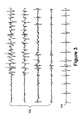
- Figure 3 is a graphical representation of various signals sensed by the medical device as shown in Figure 1 in accordance with an aspect of the invention.
- Figure 4 shows an apparatus that supports reporting neurological data in accordance with an aspect of the invention.
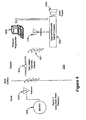
- Figure 5 is a schematic diagram of a system utilizing the above-described embodiments and allowing remote monitoring and diagnostic evaluation of at risk patients in accordance with an aspect of the invention.
- Figure 6 is a schematic diagram of an alternative system utilizing the above-described embodiments and allowing remote monitoring and diagnostic evaluation of at risk patients in accordance with an aspect of the invention.
- Figure 7 shows a first scenario of an overlap of events recording in accordance with an aspect of the invention.
- Figure 8 shows a second scenario of an overlap of events recording in accordance with an aspect of the invention.
- Figure 9 shows a third scenario with no overlap of events recording in accordance with an aspect of the invention.
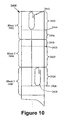
- Figure 10 shows an example of storing event data from multiple events in accordance with an aspect of the invention.
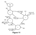
- Figure 11 shows a state transition diagram for loop recording in accordance with an aspect of the invention.
- Figure 12 shows a graphical user interface that may be used in accordance with an aspect of the invention.
- Figure 13 shows an alternative graphical user interface that may be used in accordance with an aspect of the invention.
- Figure 14 shows another example of a graphical user interface that may be used in accordance with an aspect of the invention.
- Figure 15 shows a spilt memory mode and an associated split screen graphical user _ interface in accordance with an aspect of the invention.
- an implantable medical device may consist of ECG and EEG inputs.
- the monitoring device may monitor the neural or cardiac inputs in various combinations.
- the invention may be implemented within an implantable neurostimulator system, however, as already discussed, those skilled in the art will appreciate that the techniques disclosed herein may be implemented generally within any implantable medical device system having monitoring capabilities of physiological conditions of the patient including, but not limited to, implantable drug delivery systems, implantable systems providing stimulation and drug delivery, pacemaker systems, defibrillator systems, cochlear implant systems, and implantable diagnostic system for detecting bodily conditions, including those in organs like the brain and/or the heart.
- the implantable medical device may provide therapeutic treatment to neural tissue in any number of locations in the body including, for example, the brain (which includes the brain stem), the vagus nerve, the spinal cord, peripheral nerves, etc.
- the treatment therapies can include any number of possible modalities alone or in combination including, for example, electrical stimulation, magnetic stimulation, drug infusion, brain temperature control, and/or any combination thereof.
- aspects of the invention may be embodied in various forms to analyze and treat nervous system and other disorders, namely disorders of the central nervous system, peripheral nervous system, and mental health and psychiatric disorders.
- disorders include, for example without limitation, epilepsy, Sudden Unexpected Death in Epilepsy Patients (SUDEP), Parkinson's disease, essential tremor, dystonia, multiple sclerosis (MS), anxiety (such as general anxiety, panic, phobias, post traumatic stress disorder (PTSD), and obsessive compulsive disorder (OCD)), mood disorders (such as major depression, bipolar depression, and dysthymic disorder), sleep disorders (narcolepsy), obesity, tinnitus, stroke, traumatic brain injury, Alzheimer's, and anorexia.
- SEP Sudden Unexpected Death in Epilepsy Patients
- Parkinson's disease essential tremor
- dystonia multiple sclerosis
- MS multiple sclerosis
- anxiety such as general anxiety, panic, phobias, post traumatic stress disorder (PTSD), and obsess
- the physiologic signals that are selected, stored and reported in accordance with various aspects of the invention may include any number of sensed signals.
- Such physiological signals can include, for example, electrical signals (such as EEG, ECoG and/or EKG), chemical signals, biological signals (such as change in quantity of neurotransmitters), temperature signals, pressure signals (such as blood pressure, intracranial pressure or cardiac pressure), respiration signals, heart rate signals, pH-level signals, activity signals (e.g., detected by an accelerometer), and/or peripheral nerve signals (cuff electrodes on a peripheral nerve).
- Such physiological signals may be recorded using one or more monitoring elements such as monitoring electrodes or sensors.
- monitoring elements such as monitoring electrodes or sensors.
- 6,227,203 provides examples of various types of sensors that may be used to detect a symptom or a condition or a nervous system disorder and responsively generate a neurological signal.
- various types of physiologic activities may be sensing including, for example, brain, heart and/or respiration.
- the techniques disclosed herein are suitable for use within any implantable medical device system that receives signals associated with the physiological conditions being sensed, a memory component, and a processing component (logic or software) that stores data records in data structures.
- the medical device monitors cardiac (ECG) and neural (EEG) signals and records these signals as discussed herein.
- ECG cardiac
- EEG neural
- Real-time analysis of the ECG signal evaluates rate disturbances (e.g. , bradycardia; tachycardia; asystole) as well as any indications of cardiac ischemia (e.g. , ST segment changes; T wave inversion, etc).
- rate disturbances e.g. , bradycardia; tachycardia; asystole
- any indications of cardiac ischemia e.g. , ST segment changes; T wave inversion, etc.
- Abnormalities detected during real-time analysis may lead to an immediate patient alert, which can be audible (beeps, buzzers, tones, spoken voice, etc.), light, tactile, or other means.
- Manual indication of a seizure or other event may be achieved through an external programmer device.
- the patient may push a button on the external programmer device, while communicating with the implanted device. This will provide a marker and will initiate a recording, as discussed herein, of the sensed data (for example, in the event the patient is experiencing a neurological event).
- ECG recordings may be possible (e.g. , recording all data during sleep since the incidence of SUDEP is highest in patients during sleep).
- Post-processing of the signal can occur in the implanted device, the patient's external device, a clinician external device, and/or another computing device.
- a patient may download data from the implantable device to the patient external device (as will be discussed further herein), which may then be analyzed by the external device (and/or sent through a network to the physician) to assess any ECG abnormalities. If an abnormality is detected, the device may notify the patient/caregiver.
- the patient/caregiver may inform the healthcare provider of the alert to allow a full assessment of the abnormality.
- the clinician external device may also be capable of obtaining the data from the implanted device and conducting an analysis of the stored signals. If a potentially life-threatening abnormality is detected, the appropriate medical treatment may be prescribed (e.g. , cardiac abnormality: a pacemaker, an implantable defibrillator, or a heart resynchronization device may be indicated or respiration abnormality: CAP, patient positioning, or stimulation of respiration may be indicated).
- the implantable medical device may also monitor EEG signals from intracranially implanted leads. This may allow the implanted medical device to collect cardiovascular and neurological signals in close proximity to detected neurological events as well as notify the patient/caregiver of a prolonged event (and/or status epilepticus). The implantable medical device may detect neurological events and analyze the peri-ictal signals and initiate loop recording.
- cardiac lead(s), a sensor stub, and/or a wearable patch may be used to facilitate detection of a neurological event and the recording of data and signals pre and post event.
- An integrated electrode may also be used that senses ECG signals as described in U.S. Patent No. 5,987,352 .
- the implantable medical device may warn/alert the patient 12 via buzzes, tones, beeps or spoken voice (as substantially described in U.S. Patent No. 6,067,473 ) via a piezoelectric transducer incorporated into the housing of implantable medical device. The sound may be transmitted to the patient's inner ear.
- the monitor may be implanted cranially in the patient 12 ( Figure 1 ).
- the monitor may be constructed as substantially described in U.S. Patent Nos. 5,782,891 and 6,427,086 .
- EEG sensing may be accomplished by the use of integrated electrodes in the housing of the monitor, cranially implanted leads, and or leadless EEG sensing.
- Figure 1 illustrates an implantable system 10 including an implantable medical device 100 implanted in a patient 12.
- the implantable medical device 100 continuously senses and monitors one or more physiological conditions of the patient via lead 19 and monitoring/sensing elements 30 and 32 (in the embodiment, the physiological conditions are cardiac and neurological functions of patient 12).
- Stored diagnostic data is uplinked and evaluated by an external computing device 23 (e.g. , a patient's or physician's programmer) via a 2-way telemetry, using for example, antenna 24 to relay radio frequency signals 22, 26 between implantable medical device 100 and external computing device 23.
- An external patient activator that may be located on external computing device 23 may optionally allow patient 12, or care provider (not shown), to manually activate the recording of diagnostic data.
- FIG. 2 depicts a block diagram of the electronic circuitry of implantable medical device 100 of Figure 1 in accordance with an embodiment of the invention.
- Implantable medical device 100 comprises a primary control circuit 220 and may be similar in design to that disclosed in U.S. Pat. No. 5,052,388 .
- Primary control circuit 220 includes sense amplifier circuitry 224, a crystal clock 228, a random-access memory and read-only memory (RAM/ROM) unit 230, a central processing unit (CPU) 232, digital logic circuit 238, a telemetry circuit 234, and stimulation engine circuitry 236, all of which are generally known in the art.
- Implantable medical device 100 may include internal telemetry circuit 234 so that it is capable of being programmed by means of external programmer/control unit 23 via a 2-way telemetry link.
- External programmer/control unit 23 communicates via telemetry with implantable medical device 100 so that the programmer can transmit control commands and operational parameter values to be received by the implanted device, and so that the implanted device can communicate diagnostic and operational data to the programmer 23.
- programmer 23 may be Models 9790 and CareLink® programmers, commercially available from Medtronic, Inc., Minneapolis, Minnesota.
- Various telemetry systems for providing the necessary communications channels between an external programming unit and an implanted device have been developed and are well known in the art. Suitable telemetry systems are disclosed, for example, in U.S. Patent Nos. 5,127,404 ; 4,374,382 ; and 4,556,063 .
- telemetry systems such as those described in the above referenced patents are employed in conjunction with an external programming/processing unit.
- telemetry systems for implantable medical devices employ a radio-frequency (RF) transmitter and receiver in the device, and a corresponding RF transmitter and receiver in the external programming unit.
- the transmitter and receiver utilize a wire coil as an antenna 24 for receiving downlink telemetry signals and for radiating RF signals for uplink telemetry.
- the system is modeled as an air-core coupled transformer.
- An example of such a telemetry system is shown in U.S. Patent No. 4,556,063 .
- a digital encoding scheme such as is described in U.S. Patent No. 5,127,404 can be used.
- a pulse interval modulation scheme may be employed for downlink telemetry, wherein the external programmer transmits a series of short RF "bursts" or pulses in which the interval between successive pulses (e.g. , the interval from the trailing edge of one pulse to the trailing edge of the next) is modulated according to the data to be transmitted. For example, a shorter interval may encode a digital "0" bit while a longer interval encodes a digital "1" bit.
- a pulse position modulation scheme may be employed to encode uplink telemetry data.
- a plurality of time slots are defined in a data frame, and the presence or absence of pulses transmitted during each time slot encodes the data.
- a sixteen-position data frame may be defined, wherein a pulse in one of the time slots represents a unique four-bit portion of data.
- Programming units such as the above- referenced Medtronic Models 9790 and CareLink® programmers typically interface with the implanted device through the use of a programming head or programming paddle, a handheld unit adapted to be placed on the patient's body over the implant site of the patient's implanted device.
- a magnet in the programming head effects reed switch closure in the implanted device to initiate a telemetry session. Thereafter, uplink and downlink communication takes place between the implanted device's transmitter and receiver and a receiver and transmitter disposed within the programming head.
- primary control circuit 220 includes central processing unit 232 which may be an off-the-shelf programmable microprocessor or microcontroller, but in an embodiment of the invention it may be a custom integrated circuit. Although specific connections between CPU 232 and other components of primary control circuit 220 are not shown in Figure 2 , it will be apparent to those of ordinary skill in the art that CPU 232 functions to control the timed operation of sense amplifier circuit 224 under control of programming stored in RAM/ROM unit 230. In addition to or as an alternative embodiment digital logic 238 may also be provided and utilized. In another alternative embodiment, a processing module that contains either a processor or digital circuitry may also be utilized. Those of ordinary skill in the art will be familiar with such an operative arrangement.
- crystal oscillator circuit 228 provides main timing clock signals to primary control circuit 220.
- the various components of implantable medical device 100 are powered by means of a battery (not shown), which is contained within the hermetic enclosure of implantable medical device 100. For the sake of clarity in the figures, the battery and the connections between it and the other components of implantable medical device 100 are not shown.
- Sense amplifier 224 is coupled to monitoring/sensing elements 30 and 32. Where cardiac intrinsic signals are sensed, they may sensed by sense amplifier 224 as substantially described in U.S. Patent No. 6,505,067 .
- CPU 232 or digital logic 238 allows detection of cardiac and neural electrical characteristics and anomalies. Upon detection of either a cardiac or neural anomaly, CPU 232 or digital logic 238, under control of firmware resident in RAM/ROM 230, will initiate recording of the appropriate diagnostic information into RAM of RAM/ROM 230 (discussed further herein), an may initiate a warning or alert to the patient, patient caregiver, or remote monitoring location.
- FIG. 3 shows the interplay between EEG signals 302 and ECG signal 304.
- EEG signals 302 and the ECG signal 304 may be presented to sense amplifier 224 from monitoring elements 30 and 32.
- the amplitude variation of cardiac signals may be caused by the change in thoracic cavity pressure due to respiration (i.e., inspiration and expiration).
- implantable medical device 100 may sense any number of physiologic conditions of the patient 12 for purposes of detecting, and storing data relating to, any number of the neurological events.
- various lead(s) may be used to facilitate detection of a neurological event and the recording of data and signals pre and post event.
- cardiac leads may consist of any typical lead configuration as is known in the art, such as, without limitation, right ventricular (RV) pacing or defibrillation leads, right atrial (RA) pacing or defibrillation leads, single pass RA/RV pacing or defibrillation leads, coronary sinus (CS) pacing or defibrillation leads, left ventricular pacing or defibrillation leads, pacing or defibrillation epicardial leads, subcutaneous defibrillation leads, unipolar or bipolar lead configurations, or any combinations of the above lead systems.
- RV right ventricular
- RA right atrial
- CS coronary sinus
- an electrode 32 located distally on a sensor stub may be used to facilitate detection of a neurological event and the recording of data and signals pre and post event.
- the sensor stub 32 is inserted subcutaneously in a thoracic area of the patient 12.
- the implantable medical device 100 may sense cardiac signals between an electrode on the distal end of the sensor stub and the implantable medical device case as described in conjunction with the embodiment shown in Figure 5 in U.S. Patent No. 5,987,352 .
- the implantable medical device 100 may also sense respiration parameters such as respiration rate, minute ventilation and apnea via measuring and analyzing the impedance variations measured from the implanted implantable medical device 100 case to the electrode located distally on the sensor stub lead as substantially described in U.S. Patent Nos. 4,567,892 and 4,596,251 .
- an external wearable device such as a wearable patch, a wristwatch, or a wearable computing device may be used may be used to continuously sense and implantable medical device cardiac functions of patient 12.
- a button (not shown) on the external wearable device may be activated by the patient 12 (or a caregiver) to manually activate data recording (for example, in the event the patient is experiencing a neurological event).
- the external wearable device may comprise an amplifier, memory, microprocessor, receiver, transmitter and other electronic components as substantially described in U.S. Patent No. 6,200,265 .
- the device may consist of a resilient substrate affixed to the patient's skin with the use of an adhesive.
- the substrate flexes in a complimentary manner in response to a patient's body movements providing patient comfort and wearability.
- the low profile patch is preferably similar in size and shape to a standard bandage, and may be attached to the patient's skin in an inconspicuous location.
- any number of implantable medical device systems are envisioned that may incorporate the recording and retention techniques discussed herein.
- the monitoring may be achieved using any of the above techniques in conjunction with treatment by delivery of treatment therapy (e.g. , electrical stimulation) to the brain, cardiac or respiration.
- treatment therapy e.g. , electrical stimulation
- the disclosed techniques may be implemented within any number of medical device systems (drug delivery, electrical stimulation, pacemaking, defibrillating, cochlear implant, and/or diagnostic) but configured to retain sensed data records in accordance with the teachings disclosed herein.
- the implanted medical component utilizes one or more monitoring elements (e.g. , electrodes or other sensors), a memory component having a plurality of data structures (and/or data structure types), a processing component (such as a CPU or digital logic) to process received data for storage in memory as disclosed herein, and a telemetry component.
- FIG. 4 shows apparatus 1200 that supports reporting physiological data in accordance with an aspect of the invention.
- the implanted component 1205 of the medical device system communicates with the relaying module 1215 via telemetry antenna 1210.
- the external component 1225 communicates with the relaying module 1215 via antenna 1220.
- a telemetry link 1221 between relaying module 1215 and antenna 1220 comprises a 3 MHz body wave telemetry link.
- the relaying module 1215 may communicate with the external and implanted components using differing communication schemes.
- the reverse direction and the forward direction of telemetry link 1221 may be associated with different frequency spectra. The relaying module 1215 thereby provides a greater range of communications between components of medical device system.
- an external programmer may communicate with an implanted device from a more remote location.
- the external programmer may be across the room and still be in communication via the relaying module 1215.
- the use of an implanted system is more convenient to the patient, in particular at night while sleeping or when taking a shower, eliminating the need for an external device to be worn on the body.
- the system allows the residential, hospital or ambulatory monitoring of at-risk patients and their implanted medical devices at any time and anywhere in the world.
- Medical support staff 1306 at a remote medical support center 1314 may interrogate and read telemetry from the implanted medical device and reprogram its operation while the patient 12 is at very remote or even unknown locations anywhere in the world.
- Two-way voice communications 1310 via satellite 1304, via cellular link 1332 or land lines 1356 with the patient 12 and data/programming communications with the implanted medical device 1358 via a belt worn transponder 1360 may be initiated by the patient 12 or the medical support staff 1306.
- the location of the patient 12 and the implanted medical device 1358 may be determined via GPS 1302 and link 1308 and communicated to the medical support network in an emergency. Emergency response teams can be dispatched to the determined patient location with the necessary information to prepare for treatment and provide support after arrival on the scene. See for example, U.S. Patent No. 5,752,976 .
- FIG. 1450 of Figure 6 shows a patient 12 sleeping with an implantable Monitor 1458 and/or optional therapy device as described above in connection with the above-described systems.
- the implantable device 1458 upon detection of a neurologic event may alert a remote monitoring location via local remote box 1452 (as described in U.S. Patent No. 5,752,976 ), telephone 1454 and phone lines 1456 or the patient's care provider via an RF link 1432 to a pager-sized remote monitor 1460 placed in other locations in the house or carried ( i.e. , belt worn) by the care provider 1462.
- the remote caregiver monitor 1460 may include audible buzzes/tones/beeps, vocal, light and/or vibration to alert the caregiver 1462 of patient's monitor in an alarm/alert condition.
- the RF link may include RF portable phone frequencies, power line RF links, HomeRF, Bluetooth, ZigBee, WIFI, MICS band (medical implant communications service), or any other interconnect methods as appropriate.
- the term data record encompasses the sensed physiological data, summary information, or simply a pointer that references a location in memory where the sensed physiological data is stored.
- first and second data structures envisions possibilities of storage of the sensed physiological data and the storage of their associated pointers.
- summary information data may be stored in the first and second data structures wherein the more detailed and more space consuming waveform data (pre-detection data, post-detection data, etc.) may be stored, and pointed to, in an associated memory (such as a loop record buffer).
- Mapping from entries in the first and second data structures to the waveform physiological data that is stored in the associated memory may be achieved with pointers.
- Each entry in the event log may point to its corresponding waveform data, or each waveform data may point to its corresponding data in the event log.
- multidirectional pointers in an "allocation table” or “allocation data structure” may be pointed to by the priority structures.
- the implantable medical device may have a set of monitoring elements sensing brain activity and another set of monitoring element that sense a physiological activity other than the brain (e.g. , heart activity such as a heart arrhythmia and/or respiratory activity).
- the device may then implement a detection algorithm to determine the possible onset of a possible neurological event (e.g. , a seizure) based on the sensed signals from either the first or second monitoring elements.
- a neurological event e.g. , a seizure
- data records associated with the first and second monitoring elements may be stored in memory in accordance with the teachings herein.
- the device may initiate loop recording upon indication to do so by the patient based, for example, on a patient detecting a neurological event.
- the patient initiates loop recording based on detection of a neurological event (wherein, however, the detection process of the implanted device has not detected the neurological event)
- the priority index discussed below
- loop recording may save the data for 30 seconds before the indicated seizure and 3 minutes after the seizure.
- the ECG loop recording may begin 3 to 5 minutes before the patient mark. This time period may be programmable. In another aspect of the invention, the ECG loop recording may begin before the patient mark from a time period ranging between 30 seconds to one hour. As discussed below, a subset or a composite of physiologic channels is selected from the available physiologic channels based on a selection criterion.
- a priority index may be utilized to organize different recorded events.
- the priority index may be expressed as a mathematical combination of the severity level function f(x 1 ,x 2 ,...,x n ) and the associated factor function g(y 1 ,y 2 ,...y m ).
- priority index f x 1 x 2 ... x n + g y 1 , y 2 , ... y m
- Either f(x 1 ,x 2 ,...,x n ) or g(y 1 ,y 2 ,...y m ) may be a continuous function, a discrete-value function, a Boolean function, or a combination of the above function types.
- an implanted device in response to an instruction from a clinician, organizes stored physiological data according to the associated priority index and reports a predetermined number of data records that are deemed as having a higher priority index than the other stored data records.
- the above approach may be extended to include the retention of more than one channel from a channel list sorted by relevancy as determined by a function of various factors (e.g. , onset time, presence and severity of an event) as previously discussed.
- the selection of physiologic channels may occur after filtering (e.g. , bandpass, notch, FIR, and IIR) the physiologic channels.
- filtering e.g. , bandpass, notch, FIR, and IIR
- an EEG signal may be filtered in the 10-60 Hz range to remove the bulk of the EEG energy content that may otherwise mask the ictal content.
- the physiologic channels may be filtered in the 180-250 Hz range in order to study "fast-ripple" events.
- all events are logged into an event recorder regardless of whether data specific to a particular event is saved or overwritten due to full memory.
- all pre-event and post-event times may be the same for all events. However, as those skilled in the art will realize both pre-event and post-event times may be adjusted such that the total time saved for each event remains the same.
- Zone events refer to specific events which may be triggered automatically by various algorithms or other inputs for example telemetry commands from a patient device.
- Other inputs may include a manual trigger issued by a patient or healthcare provider.
- various types of triggers may cause the implantable medical device to store waveform data.
- the triggers may include an implantable seizure detection algorithm which monitors EEG channels for seizure activity.
- the triggers may include cardiac arrhythmia detection logic to monitor ECG signals.
- the triggers may include manual triggers operated by a patient through a patient programmer.
- an implantable medical device stores loop recording of waveform data having specified pre-event and post-event times.
- the implantable medical device includes a multitude of sense channels to process numerous signal types.
- Overlaps as used in the below examples occur when the storing of data related to a second event overlaps the storing of data from a first event. Because data relating to both events may be stored non-redundantly, memory capacity for additional events is diminished.
- a first event 2102 is illustrated along with its associated first event recording 2103.
- the first event recording 2103 includes a pre-event time 2104 and a post-event time 2106.
- a second event or zone A event 2108 is also illustrated in Figure 7 along with its associated second event recording 2109.
- a zone A overlap occurs after the first event 2102 and while the implantable device is still writing the post-event section 2106 of the first event recording 2103.
- the zone A overlap time period is labeled as "A" (2110) in Figure 7 .
- the zone A event 2108 includes a pre-event time 2111 and post-event time 2112.
- the zone A event recording 2109 is illustrated as a dotted box to show the recording that would have been made had event 2108 occurred without the occurrence of event 2102.
- a separate second loop recording 2109 does not need be recorded as recording 2103 is already storing waveform data that contains event 2108.
- a second loop recording 2109 is not captured as it would duplicate data already stored in memory.
- event 2108 does not generate a separate loop recording an entry would be generated in an event log to log the occurrence of the zone A event 2108.
- Figure 8 illustrates a second overlapping scenario in accordance with an aspect of the invention.
- a first event 2202 is shown along with its associated first event recording 2203.
- the first event recording 2203 includes a pre-event time 2204 and a post-event time 2206.
- a zone B event 2208 is also illustrated in Figure 8 along with its associated zone B event recording 2209.
- a zone B overlap may occur when the zone B event 2208 occurs later than the end of the post-event section 2206 of the first event recording 2203, but early enough that there would be overlap between the first event recording 2203 and the zone B recording 2209.
- the zone B overlap time is labeled as "B" (2210) in Figure 8 .
- the zone B event 2208 includes a pre-event time 2211 and post-event time 2212.
- the zone B event recording 2209 is illustrated as a dotted box to show that this loop does not get recorded.
- Event recording 2209 shows the timing of the loop that would have been recorded had the event occurred independently of event 2202.
- a second recording 2214 begins to write immediately after completion of the first event recording 2203 as illustrated by recording 2214.
- the second recording 2214 includes a second pre-event time 2216 and a second post-event time 2218.
- the second event recording 2214 includes the same information as the zone B event recording 2209 except that the pre-event time intervals and post-event time intervals have been modified. However, the total recording time for each of the second event recording 2214 and zone B recording 2209 remains the same.
- the second event recording 2214 results in two contiguous blocks of data, 2203 and 2214, stored in memory of the implantable device. However, the two recordings may be considered separate for the purposes of a priority algorithm.
- the ISDA trigger may be considered more important than the end of cluster event.
- the second loop recording may get overwritten before the first loop recording if the memory was filled and space was needed for a new loop recording.
- Figure 9 shows a third scenario in which overlapping does not occur.
- a first event 2302 is shown along with its associated first event recording 2303.
- the first event recording 2303 includes a pre-event time 2304 and a post-event time 2306.
- a zone C event 2308 is also illustrated in Figure 9 along with its associated zone C event recording 2309.
- the zone C recording 2309 includes a pre-event time 2311 and post-event time 2312.
- a zone C event 2308 occurs when the event is late enough that there would be no overlap between two event loops. This time period is labeled as "C" (2310) in Figure 9 .
- the zone C recording 2309 may be written to memory.
- a time gap 2314 may exist between the first event recording 2303 and a zone C recording 2309.
- Figure 10 illustrates an example of storing event data for multiple events, the events being triggered by different event triggers.
- Figure 11 illustrates a state transition diagram which will be discussed in relation to the illustrative example of Figure 10 .
- Figure 10 three blocks of memory 2402, 2404, and 2406 are displayed for memory 2408.
- memory 2408 may contain numerous blocks for data storage.
- memory blocks 2402, 2404, and 2406 are shown as consecutive memory locations for illustrative purposes but as those skilled in the art will realize these displayed consecutive memory locations are not meant to be limiting as non-consecutive memory locations may also be used in accordance with various aspects of the invention.
- a loop recording begins in memory block 2402.
- a transition is made from the "start" position 2502 to state "0" 2504.
- State "0" 2504 may be entered whenever a new memory block starts to be written, such as upon startup 2502.
- loop recording may occur at position 2410 loop recording may occur.
- wrap-around may occur as illustrated at 2412.
- a wrap-around 2505 occurs a transition is made from a state "0" 2504 to a state "1" 2506. Any number of wrap-arounds may occur while the recording is in this state. Numerous wrap-arounds 2507 may occur as illustrated in Figure 11 in state "1" 2506.
- a pointer may be stored to unroll the loop recording in the right order.
- the event may be an event such as an ISDA (implantable seizure detection algorithm) trigger which monitors EEG channels for seizure activity.
- ISDA implantable seizure detection algorithm
- transition state diagram of Figure 11 when the transition occurs in state "1" 2506, it may be a zone "C” event 2508 and a transition is made from state “1" 2506 to state "3" 2509. State “3" 2509 may ensure that a full pattern has been written to a pre-event portion of an event recording before moving to a post-event recording.
- state "3" may be present to deal with differences in per channel data rate, which can vary due to differences in data compression settings, for example. If a full pattern has not been written to a pre-event portion of an event recording then a transition may not be made from state "3" 2509 as it may loop around in loop 2510.
- State “2" 2512 may occur when a loop recording has been committed to be made. Any events that occur while the system is in state “2" 2512 may be zone A events 2514. Referring back to Figure 10 at position 2416, the post-event portion is being recorded in memory block 2402. During this time any number of additional zone A events may occur. The zone A events 2514 get logged but may not trigger any further storage of data beyond the memory block that has already been committed. All data written into memory during this state may go into the post-event portion of the event recording.
- the system may transition from state "2" 2512 to state "0" 2504 and begin to write into a new memory block.
- the post-event recording may continue into a memory block 2404 as illustrated in Figure 10 at position 2418.
- a zone B event occurs.
- memory block 2404 is contiguous with memory block 2402.
- the zone B event may be marked and in Figure 11 a transition from state "0" 2504 to state "2" 2512 may be completed. As wrap-around did not occur just prior to the zone B event the pre-event recording of the zone B event will be shorter than the pre-event recording of the earlier recorded event.
- the loop recording may be continued into memory block 2406.
- memory block 2406 As data is being written into a new memory block, memory block 2406, a transition from state "2" 2512 to state “0" 2504 may be accomplished. While in state "0", the system may search for additional zone B events.
- a pointer may reach a pre/post boundary with no additional zone B events. As no additional zone B events have occurred, at position 2428 the system may continue to loop record. As the system may be in wrap-around, a transition from state "0" 2504 to state "1" 2506 may be completed. Next, the system may search or wait for a zone C event. Memory block 2406 may or may not be contiguous with memory block 2404. If no event occurs before uplink, memory block 2406 may not be uplinked for analysis.
- a zone B event may not require a trip to state "3" 2509, because the loop recording may not need to be unrolled.
- the block size may ensure that an integer number of full patterns will be in the block.
- Figure 12 shows a graphical user interface 2602 that may be used in accordance with various aspects of the invention.
- a device having a fixed amount of memory may use this graphical interface to determine the number of loop recording 2604 that may be stored in the device.
- an implantable device may have a total of 2 MB of memory to store log and loop recording data. A certain portion of the memory may be needed to store or log events in an event log or for other non-loop recording storage purposes. This space may be on the order of 200 K of memory. The remaining 1.8 MB of memory may be allocated for storing waveform data associated with the events.
- a device such as an implantable device may have more or less memory for use in storing waveform and other data.
- the allocation of memory may be configurable. The above example in only one illustrative example and is not intended to limit the described aspects of the invention.
- the selected criteria may include a pre-trigger time 2606, a post-trigger time 2608, and a total time 2610.
- the selected pre-trigger time 2606 may be 60 seconds
- the selected post-trigger time 2608 may be 30 seconds.
- the total time 2610 may be the result of the pre-trigger time 2606 and the post-trigger time 2608, ninety seconds.
- the amount of time selected for the pre-trigger time 2606 and post-trigger time 2608 may depend on the frequency of events and other factors considered by a user. For example, a physician or other caregiver may set the pre-trigger time 2606 and post-trigger time 2608 based on the type of event which they expect to record in order to produce useful data for analysis.
- various channels may be enabled to collect event information. For instance, a physician or caregiver may select to record information from EEG channel “1" 2612, EEG channel “2" 2614, EEG channel “3” 2616, and EEG channel "4" 2618.
- data relating to an ECG channel 2620 may also be recorded.
- the number and type of channels selected may affect the maximum number of loop recording 2604 that may be saved. In particular, increasing the number of enabled channels to be recorded decreases the maximum number of loop recordings that that may be saved in the device.
- Figure 12 illustrates that with EEG channels 1-4 (2612-2618) and ECG channel 2620 enabled and with a pre-trigger time 2606 of 60 seconds and a post-trigger time 2608 of 30 seconds, the number of loop recording 2604 that may be saved is "52" (2680).
- Figure 13 if only one channel is selected such as EEG channel "1" 2612 and the pre-trigger time 2606 of 60 seconds and the post-trigger time 2608 of 30 seconds remains the same, the number of loop recording 2604 that may be saved increases to "318" (2780).
- a physician or caregiver may obtain a particular number of loop recording 2604 to analyze.
- data compression may be used to store an additional number of loop recording or a longer record time for the same number of loop recording.
- Figure 12 illustrates fixed ratio data compression for multiple types of physiologic signal channels (both EEG and ECG).
- EEG compression ratio 2622 may be selected by a physician or caregiver. Because an objective of loop recording may be to provide to physician or caregiver with waveforms for visual analysis, the data compression may be lossy, as long as it does not distort the signal to the point where the physician or caregiver is unable to make an accurate diagnosis.
- EEG channels are available (2612-2618) and enabled for recording ( Figure 12 ).
- all enabled EEG channels (2612-2618) may have the same compression settings.
- the ratios 2622 may include the following compression ratios as shown in Table 1. Table I also includes a brief description of the compression technique that may be implemented to achieve the selected compression ratio. Table 1: EEG Compression 1:1 No compression 2:1 Delta companding 4:1 NTP, delta companding 8:1 NTP, NTP, delta companding 16:1 NTP, NTP, range companding, D/R
- the EEG compression ratios 2622 may be selectable through use of a dropdown box in graphical user interface 2602. In Figure 12 , the EEG compression ratio is "8" (2690).
- ECG channel 2620 may also be available for compression.
- ECG channel 2620 may be compressed using an ECG compression ratio 2624 as illustrated in Table 2.
- Table 2 also includes a brief description of the compression technique that may be implemented to achieve the selected compression ratio. Table 2: ECG Compression 1:1 No compression 2:1 Delta companding 4:1 NTP, delta companding
- the ECG compression ratios 2624 may also be selectable through use of a dropdown box in graphical user interface 2602.
- the EEG compression ratio is "4" (2692).
- the number of loop recording based on the selected channels (EEG and ECG), compression ratios (EEG and ECG), and selected times (2606 and 2608) is "52" (2680).
- compression ratios for either the EEG, ECG, or other physiologic signal channels or any combination thereof may be utilized as the physician or clinician may desire to set compression parameters not listed in these tables.
- an advanced compression settings widget e.g. button or tab; not shown
- all compression settings may be placed in an advanced dialog box to simplify the main loop recording user interface.
- FIG 14 A change in the compression ratios for EEG channels (2612-2618) and ECG channel (2620) is illustrated in Figure 14 , in accordance with an aspect of the invention.
- the EEG compression ratio 2622 is "1" (2890) and the ECG compression ratio 2624 is "2" (2892).
- the number of associated loop recording 2604 based on the selected factors in user interface 2602 is "7" (2880). As illustrated, the number of loop recording has been reduced from “52" (2680) to "7" (2880).
- Figure 15 represents a spilt memory mode in accordance with an aspect of the invention.
- the split memory mode may include two separate instances of a loop recording algorithm, each operating independently.
- the split screen graphical user interface of Figure 15 may allow both separate instances of a loop recording algorithm to be configured independently.
- a spilt screen graphical user interface 2900 comprising a left half screen 2902 and a right half screen 2904. Both screens contain similar selection criteria for determining a number of loop recordings to be recorded.
- Spilt screen graphical user interface 2900 may be used to allow two different configurations for loop recording. The different configurations may each be apportioned an amount of memory to be used for loop recordings. For example, a slider 2906 may be used to split the available waveform memory between the two different configurations.
- a total amount of memory useable for waveform loop recording may be 1,800,000 bytes.
- the 1,800,000 bytes of memory for waveform loop recording may be based on a 2 MB memory capacity, less storage for other non-waveform data.
- the slider 2906 may adjust the amount of memory apportioned to each of the different configurations.
- a first configuration 2908 may have available 828,000 bytes (2910) of memory whereas a second configuration (2912) may have 972,000 bytes (2914) of memory available for loop recordings.
- the 828,000 bytes (2910) of memory may allow "23" (2916) loop recordings based on the selected criteria as illustrated in left hand screen 2902.
- 972,000 bytes (2914) of memory may allow "16" (2918) loop recordings based on the selected criteria.
Landscapes
- Health & Medical Sciences (AREA)
- Life Sciences & Earth Sciences (AREA)
- Engineering & Computer Science (AREA)
- Public Health (AREA)
- Biophysics (AREA)
- Pathology (AREA)
- Biomedical Technology (AREA)
- Heart & Thoracic Surgery (AREA)
- Medical Informatics (AREA)
- Molecular Biology (AREA)
- Surgery (AREA)
- Animal Behavior & Ethology (AREA)
- General Health & Medical Sciences (AREA)
- Physics & Mathematics (AREA)
- Veterinary Medicine (AREA)
- Neurology (AREA)
- Neurosurgery (AREA)
- Physiology (AREA)
- Computer Networks & Wireless Communication (AREA)
- Radar, Positioning & Navigation (AREA)
- Dentistry (AREA)
- Oral & Maxillofacial Surgery (AREA)
- Human Computer Interaction (AREA)
- Psychiatry (AREA)
- Psychology (AREA)
- Measuring And Recording Apparatus For Diagnosis (AREA)
- Electrotherapy Devices (AREA)
- Management, Administration, Business Operations System, And Electronic Commerce (AREA)
- Medical Treatment And Welfare Office Work (AREA)
Claims (12)
- Verfahren zum Handhaben mehrerer Schleifenaufzeichnungen bzw. einer Mehrfachschleifenaufzeichnung in einer implantierbaren Vorrichtung, wobei das Verfahren umfasst:Schritt a: Überwachen einer ersten Signalmenge, die erste Signalform-Daten enthält, wobei die ersten Signalform-Daten einem physiologischen Zustand zugeordnet sind;Schritt b: Detektieren eines ersten Ereignisses;Schritt c: Starten einer ersten Schleifenaufzeichnung, wobei die erste Schleifenaufzeichnung durch das erste Ereignis aktiviert wird, wobei die erste Schleifenaufzeichnung wenigstens einen Anteil der Signalform-Daten der ersten Signalmenge speichert, wobei die erste Schleifenaufzeichnung eine Vorereigniszeit und eine Nachereigniszeit umfasst;Schritt d: Überwachen einer zweiten Signalmenge, die zweite Signalform-Daten enthält;Schritt e: Detektieren eines zweiten Ereignisses;Schritt f: Bestimmen, ob eine Überlappung der Daten zwischen der ersten Schleifenaufzeichnung und einer zweiten Schleifenaufzeichnung, die dem zweiten Ereignis zugeordnet ist, auftritt; undSchritt g: Bestimmen, ob die zweite Schleifenaufzeichnung zu starten ist, basierend auf der Bestimmung im Schritt f;wobei dann, wenn eine Überlappung der Daten auftritt, wie im Schritt f bestimmt wird, der Schritt g ferner umfasst:Schritt i: Bestimmen, ob das zweite Ereignis nach dem Aufzeichnen der Nachereigniszeit der ersten Schleifenaufzeichnung auftritt; unddann, wenn im Schritt i das zweite Ereignis nach dem Aufzeichnen der Nachereigniszeit der ersten Schleifenaufzeichnung auftritt,Schritt ii: Starten der zweiten Schleifenaufzeichnung nach dem Abschluss der ersten Schleifenaufzeichnung.
- Verfahren nach Anspruch 1, wobei die erste Signalmenge und die zweite Signalmenge gleich sind.
- Verfahren nach Anspruch 1, wobei das erste Ereignis einen ersten Auslöser umfasst, wobei der erste Auslöser einen Elektrokardiogramm-Auslöser oder einen Anfalldetektionsalgorithmus-Auslöser oder einen manuellen Auslöser enthält.
- Verfahren nach Anspruch 1, wobei das zweite Ereignis einen zweiten Auslöser umfasst, wobei der zweite Auslöser einen Elektrokardiogramm-Auslöser oder einen Anfalldetektionsalgorithmus-Auslöser oder einen manuellen Auslöser enthält.
- Verfahren nach Anspruch 1, wobei, wenn eine Überlappung der Daten nicht auftritt, wie im Schritt f bestimmt wird, dann im Schritt g die zweite Schleifenaufzeichnung gestartet wird.
- Verfahren nach Anspruch 1, wobei, wenn eine Überlappung der Daten auftritt, wie im Schritt f bestimmt wird, dann der Schritt g ferner umfasst:Schritt I: Bestimmen, ob das zweite Ereignis auftritt, während die Nachereigniszeit der ersten Schleifenaufzeichnung aufgezeichnet wird; unddann, wenn im Schritt I das zweite Ereignis auftritt, während die Nachereigniszeit der ersten Schleifenaufzeichnung aufgezeichnet wird,Schritt II: Abschließen der ersten Schleifenaufzeichnung und nicht Starten der zweiten Schleifenaufzeichnung.
- Verfahren nach Anspruch 1, wobei die erste Schleifenaufzeichnung und die zweite Schleifenaufzeichnung zusammenhängend sind.
- Verfahren nach Anspruch 1, wobei die erste Schleifenaufzeichnung und die zweite Schleifenaufzeichnung im Wesentlichen ähnliche Aufzeichnungszeiten umfassen.
- Implantierbare medizinische Vorrichtung, die enthält:(a) ein erstes Überwachungselement (30), das eine erste Signalmenge empfängt, die einem physiologischen Zustand zugeordnet ist;(b) ein zweites Überwachungselement (32), das eine zweite Signalmenge empfängt;(c) ein Speichermedium (230); und(d) ein Verarbeitungsmodul (232), das an das Speichermedium gekoppelt ist und mit computerausführbaren Befehlen programmiert ist, um auszuführen:Schritt i: Detektieren eines ersten Ereignisses;Schritt ii: Starten einer ersten Schleifenaufzeichnung, wobei die erste Schleifenaufzeichnung durch das erste Ereignis aktiviert wird, wobei die erste Schleifenaufzeichnung die Signalform-Daten der ersten Signalmenge in dem Speichermedium speichert, wobei die erste Schleifenaufzeichnung eine Vorereigniszeit und eine Nachereigniszeit umfasst;Schritt iii: Detektieren eines zweiten Ereignisses;Schritt iv: Bestimmen, ob eine Überlappung der Signalform-Daten zwischen der ersten Schleifenaufzeichnung und einer zweiten Schleifenaufzeichnung, die dem zweiten Ereignis zugeordnet ist, auftritt; undSchritt v: Bestimmen, ob die zweite Schleifenaufzeichnung zu starten ist, basierend auf der Bestimmung im Schritt iv;
wobei dann, wenn eine Überlappung auftritt, wie im Schritt iv bestimmt wird, der Schritt v ferner umfasst:Schritt I: Bestimmen, ob das zweite Ereignis nach dem Aufzeichnen der Nachereigniszeit der ersten Schleifenaufzeichnung auftritt; unddann, wenn im Schritt I das zweite Ereignis nach dem Aufzeichnen der Nachereigniszeit der ersten Schleifenaufzeichnung auftritt,Schritt II: Starten der zweiten Schleifenaufzeichnung nach dem Abschluss der ersten Schleifenaufzeichnung. - Vorrichtung nach Anspruch 9, wobei das Verarbeitungsmodul ferner mit computerausführbaren Befehlen programmiert ist, wobei dann, falls eine Überlappung auftritt, wie im Schritt iv bestimmt wird, der Schritt v ferner umfasst:Schritt III: Bestimmen, ob das zweite Ereignis auftritt, während die Nachereigniszeit der ersten Schleifenaufzeichnung aufgezeichnet wird; unddann, wenn im Schritt III das zweite Ereignis auftritt, während die Nachereigniszeit der ersten Schleifenaufzeichnung aufgezeichnet wird,Schritt IV: Abschließen der ersten Schleifenaufzeichnung und nicht Starten der zweiten Schleifenaufzeichnung.
- Vorrichtung nach Anspruch 10, wobei das im Schritt i detektierte erste Ereignis einer Gehirnaktivität zugeordnet ist und das im Schritt iii detektierte zweite Ereignis einer Herzaktivität zugeordnet ist.
- Vorrichtung nach Anspruch 11, wobei die Gehirnaktivität einen Anfall umfasst und die Herzaktivität eine Herzarrhythmie umfasst.
Applications Claiming Priority (2)
| Application Number | Priority Date | Filing Date | Title |
|---|---|---|---|
| US11/380,575 US7610083B2 (en) | 2006-04-27 | 2006-04-27 | Method and system for loop recording with overlapping events |
| PCT/US2007/006365 WO2007130217A1 (en) | 2006-04-27 | 2007-03-14 | Method and system for loop recording with overlapping events |
Publications (2)
| Publication Number | Publication Date |
|---|---|
| EP2023809A1 EP2023809A1 (de) | 2009-02-18 |
| EP2023809B1 true EP2023809B1 (de) | 2011-09-28 |
Family
ID=38294214
Family Applications (1)
| Application Number | Title | Priority Date | Filing Date |
|---|---|---|---|
| EP07753024A Not-in-force EP2023809B1 (de) | 2006-04-27 | 2007-03-14 | Verfahren und system zur schlaufenaufzeichnung mit überlappenden ereignissen |
Country Status (4)
| Country | Link |
|---|---|
| US (1) | US7610083B2 (de) |
| EP (1) | EP2023809B1 (de) |
| AT (1) | ATE525955T1 (de) |
| WO (1) | WO2007130217A1 (de) |
Families Citing this family (67)
| Publication number | Priority date | Publication date | Assignee | Title |
|---|---|---|---|---|
| US9050469B1 (en) | 2003-11-26 | 2015-06-09 | Flint Hills Scientific, Llc | Method and system for logging quantitative seizure information and assessing efficacy of therapy using cardiac signals |
| US9314633B2 (en) | 2008-01-25 | 2016-04-19 | Cyberonics, Inc. | Contingent cardio-protection for epilepsy patients |
| US8565867B2 (en) | 2005-01-28 | 2013-10-22 | Cyberonics, Inc. | Changeable electrode polarity stimulation by an implantable medical device |
| US8260426B2 (en) | 2008-01-25 | 2012-09-04 | Cyberonics, Inc. | Method, apparatus and system for bipolar charge utilization during stimulation by an implantable medical device |
| US7996079B2 (en) | 2006-01-24 | 2011-08-09 | Cyberonics, Inc. | Input response override for an implantable medical device |
| ES2573323T3 (es) | 2006-03-29 | 2016-06-07 | Dignity Health | Estímulo eléctrico de microrráfaga de nervios craneales para el tratamiento de afecciones médicas |
| US7912537B2 (en) * | 2006-04-27 | 2011-03-22 | Medtronic, Inc. | Telemetry-synchronized physiological monitoring and therapy delivery systems |
| US7962220B2 (en) | 2006-04-28 | 2011-06-14 | Cyberonics, Inc. | Compensation reduction in tissue stimulation therapy |
| US7869885B2 (en) | 2006-04-28 | 2011-01-11 | Cyberonics, Inc | Threshold optimization for tissue stimulation therapy |
| US7869867B2 (en) | 2006-10-27 | 2011-01-11 | Cyberonics, Inc. | Implantable neurostimulator with refractory stimulation |
| US7778699B1 (en) * | 2007-04-26 | 2010-08-17 | Pacesetter, Inc. | System and method for trigger-specific recording of cardiac signals using an implantable medical device |
| US7974701B2 (en) | 2007-04-27 | 2011-07-05 | Cyberonics, Inc. | Dosing limitation for an implantable medical device |
| US8337404B2 (en) | 2010-10-01 | 2012-12-25 | Flint Hills Scientific, Llc | Detecting, quantifying, and/or classifying seizures using multimodal data |
| US8571643B2 (en) | 2010-09-16 | 2013-10-29 | Flint Hills Scientific, Llc | Detecting or validating a detection of a state change from a template of heart rate derivative shape or heart beat wave complex |
| US8382667B2 (en) | 2010-10-01 | 2013-02-26 | Flint Hills Scientific, Llc | Detecting, quantifying, and/or classifying seizures using multimodal data |
| US8161497B2 (en) * | 2008-03-26 | 2012-04-17 | Tektronix, Inc. | Holdoff algorithm for no dead time acquisition |
| US7868689B2 (en) * | 2008-04-08 | 2011-01-11 | Qualcomm Incorporated | Low power slicer-based demodulator for PPM |
| US8204603B2 (en) | 2008-04-25 | 2012-06-19 | Cyberonics, Inc. | Blocking exogenous action potentials by an implantable medical device |
| WO2010014686A1 (en) | 2008-07-30 | 2010-02-04 | Aleva Neurotherapeutics, S.A. | Apparatus and method for optimized stimulation of a neurological target |
| US8457747B2 (en) | 2008-10-20 | 2013-06-04 | Cyberonics, Inc. | Neurostimulation with signal duration determined by a cardiac cycle |
| US8417344B2 (en) | 2008-10-24 | 2013-04-09 | Cyberonics, Inc. | Dynamic cranial nerve stimulation based on brain state determination from cardiac data |
| WO2010055421A1 (en) | 2008-11-12 | 2010-05-20 | Aleva Neurotherapeutics, S.A. | Microfabricated neurostimulation device |
| US20100191304A1 (en) | 2009-01-23 | 2010-07-29 | Scott Timothy L | Implantable Medical Device for Providing Chronic Condition Therapy and Acute Condition Therapy Using Vagus Nerve Stimulation |
| US9844333B2 (en) | 2009-03-24 | 2017-12-19 | International Business Machines Corporation | Remote delivery and monitoring of health care |
| US8239028B2 (en) | 2009-04-24 | 2012-08-07 | Cyberonics, Inc. | Use of cardiac parameters in methods and systems for treating a chronic medical condition |
| US8827912B2 (en) | 2009-04-24 | 2014-09-09 | Cyberonics, Inc. | Methods and systems for detecting epileptic events using NNXX, optionally with nonlinear analysis parameters |
| US20100280336A1 (en) * | 2009-04-30 | 2010-11-04 | Medtronic, Inc. | Anxiety disorder monitoring |
| CN105844087A (zh) * | 2009-04-30 | 2016-08-10 | 麦德托尼克公司 | 以基于支持向量机的算法为基础的病人状态探测 |
| WO2011067297A1 (en) | 2009-12-01 | 2011-06-09 | ECOLE POLYTECHNIQUE FéDéRALE DE LAUSANNE | Microfabricated neurostimulation device and methods of making and using the same |
| US9717439B2 (en) | 2010-03-31 | 2017-08-01 | Medtronic, Inc. | Patient data display |
| US9549708B2 (en) | 2010-04-01 | 2017-01-24 | Ecole Polytechnique Federale De Lausanne | Device for interacting with neurological tissue and methods of making and using the same |
| US8296108B2 (en) * | 2010-04-02 | 2012-10-23 | Yugen Kaisha Suwa Torasuto | Time series data analyzer, and a computer-readable recording medium recording a time series data analysis program |
| US8831732B2 (en) | 2010-04-29 | 2014-09-09 | Cyberonics, Inc. | Method, apparatus and system for validating and quantifying cardiac beat data quality |
| US8562536B2 (en) | 2010-04-29 | 2013-10-22 | Flint Hills Scientific, Llc | Algorithm for detecting a seizure from cardiac data |
| US8649871B2 (en) | 2010-04-29 | 2014-02-11 | Cyberonics, Inc. | Validity test adaptive constraint modification for cardiac data used for detection of state changes |
| US20110288417A1 (en) * | 2010-05-19 | 2011-11-24 | Intouch Technologies, Inc. | Mobile videoconferencing robot system with autonomy and image analysis |
| US8679009B2 (en) | 2010-06-15 | 2014-03-25 | Flint Hills Scientific, Llc | Systems approach to comorbidity assessment |
| US8641646B2 (en) | 2010-07-30 | 2014-02-04 | Cyberonics, Inc. | Seizure detection using coordinate data |
| JP5710767B2 (ja) | 2010-09-28 | 2015-04-30 | マシモ コーポレイション | オキシメータを含む意識深度モニタ |
| US8684921B2 (en) | 2010-10-01 | 2014-04-01 | Flint Hills Scientific Llc | Detecting, assessing and managing epilepsy using a multi-variate, metric-based classification analysis |
| US9323250B2 (en) | 2011-01-28 | 2016-04-26 | Intouch Technologies, Inc. | Time-dependent navigation of telepresence robots |
| US9504390B2 (en) | 2011-03-04 | 2016-11-29 | Globalfoundries Inc. | Detecting, assessing and managing a risk of death in epilepsy |
| US8725239B2 (en) | 2011-04-25 | 2014-05-13 | Cyberonics, Inc. | Identifying seizures using heart rate decrease |
| US9402550B2 (en) | 2011-04-29 | 2016-08-02 | Cybertronics, Inc. | Dynamic heart rate threshold for neurological event detection |
| US9098611B2 (en) | 2012-11-26 | 2015-08-04 | Intouch Technologies, Inc. | Enhanced video interaction for a user interface of a telepresence network |
| US10206591B2 (en) | 2011-10-14 | 2019-02-19 | Flint Hills Scientific, Llc | Seizure detection methods, apparatus, and systems using an autoregression algorithm |
| US10448839B2 (en) | 2012-04-23 | 2019-10-22 | Livanova Usa, Inc. | Methods, systems and apparatuses for detecting increased risk of sudden death |
| US9361021B2 (en) | 2012-05-22 | 2016-06-07 | Irobot Corporation | Graphical user interfaces including touchpad driving interfaces for telemedicine devices |
| WO2013176758A1 (en) | 2012-05-22 | 2013-11-28 | Intouch Technologies, Inc. | Clinical workflows utilizing autonomous and semi-autonomous telemedicine devices |
| US10220211B2 (en) | 2013-01-22 | 2019-03-05 | Livanova Usa, Inc. | Methods and systems to diagnose depression |
| US10692591B2 (en) | 2013-02-01 | 2020-06-23 | B-Line Medical, Llc | Apparatus, method and computer readable medium for tracking data and events |
| WO2015173787A1 (en) | 2014-05-16 | 2015-11-19 | Aleva Neurotherapeutics Sa | Device for interacting with neurological tissue and methods of making and using the same |
| US11311718B2 (en) | 2014-05-16 | 2022-04-26 | Aleva Neurotherapeutics Sa | Device for interacting with neurological tissue and methods of making and using the same |
| US20170143212A1 (en) * | 2014-05-20 | 2017-05-25 | Shimadzu Corporation | Optical measurement system and optical brain function measurement method |
| WO2016017493A1 (ja) * | 2014-07-28 | 2016-02-04 | オリンパス株式会社 | 内視鏡システム |
| US9403011B2 (en) | 2014-08-27 | 2016-08-02 | Aleva Neurotherapeutics | Leadless neurostimulator |
| US9474894B2 (en) | 2014-08-27 | 2016-10-25 | Aleva Neurotherapeutics | Deep brain stimulation lead |
| BR112017003976A2 (pt) | 2014-09-02 | 2018-02-20 | Koninklijke Philips Nv | método para mitigar alertas falso-positivos para padrões de ecg isquêmicos em um eletrocardiograma (ecg) indicativos de isquemia ou infarto do miocárdio, processador, e sistema que facilita a mitigação de alertas falso-positivos ao monitorar elevação de st em um eletrocardiograma (ecg) indicativo de isquemia ou infarto do miocárdio |
| WO2016057553A1 (en) | 2014-10-07 | 2016-04-14 | Masimo Corporation | Modular physiological sensors |
| WO2017134587A1 (en) | 2016-02-02 | 2017-08-10 | Aleva Neurotherapeutics, Sa | Treatment of autoimmune diseases with deep brain stimulation |
| EP3684463A4 (de) | 2017-09-19 | 2021-06-23 | Neuroenhancement Lab, LLC | Verfahren und vorrichtung für neuro-enhancement |
| US11717686B2 (en) | 2017-12-04 | 2023-08-08 | Neuroenhancement Lab, LLC | Method and apparatus for neuroenhancement to facilitate learning and performance |
| WO2019133997A1 (en) | 2017-12-31 | 2019-07-04 | Neuroenhancement Lab, LLC | System and method for neuroenhancement to enhance emotional response |
| US10702692B2 (en) | 2018-03-02 | 2020-07-07 | Aleva Neurotherapeutics | Neurostimulation device |
| US11364361B2 (en) | 2018-04-20 | 2022-06-21 | Neuroenhancement Lab, LLC | System and method for inducing sleep by transplanting mental states |
| CN113382683A (zh) | 2018-09-14 | 2021-09-10 | 纽罗因恒思蒙特实验有限责任公司 | 改善睡眠的系统和方法 |
| CN110403603B (zh) * | 2019-08-07 | 2023-06-23 | 龙岩学院 | 一种用于辅助癫痫手术的监测设备 |
Family Cites Families (45)
| Publication number | Priority date | Publication date | Assignee | Title |
|---|---|---|---|---|
| US3958563A (en) * | 1974-11-06 | 1976-05-25 | Heriberto Fernandez | Two speed system for EEG recording |
| US4556063A (en) * | 1980-10-07 | 1985-12-03 | Medtronic, Inc. | Telemetry system for a medical device |
| US4374382A (en) * | 1981-01-16 | 1983-02-15 | Medtronic, Inc. | Marker channel telemetry system for a medical device |
| US4485813A (en) * | 1981-11-19 | 1984-12-04 | Medtronic, Inc. | Implantable dynamic pressure transducer system |
| IT1156564B (it) * | 1982-03-16 | 1987-02-04 | Gianni Plicchi | Elettrostimolatore cardiaco impiantabile, di tipo fisiologico, in cui la frequenza di stimolazione e'regolata dalla frequenza respiratoria del paziente |
| US4583553A (en) * | 1983-11-15 | 1986-04-22 | Medicomp, Inc. | Ambulatory ECG analyzer and recorder |
| EP0151689B1 (de) * | 1984-02-07 | 1990-12-27 | SCHIAPPARELLI MEDTRONIC S.p.A. | Herzschrittmacher, abhängig vom Atmungsumfang pro Zeiteinheit |
| US4648165A (en) * | 1984-11-09 | 1987-03-10 | Whitehorne Gary R | Metal frame (spring puller) |
| US4903701A (en) * | 1987-06-05 | 1990-02-27 | Medtronic, Inc. | Oxygen sensing pacemaker |
| US5007431A (en) * | 1988-05-03 | 1991-04-16 | Care Systems, Inc. | Apparatus and method for updated recording of irregularities in an electrocardiogram waveform |
| US5000189A (en) * | 1989-11-15 | 1991-03-19 | Regents Of The University Of Michigan | Method and system for monitoring electrocardiographic signals and detecting a pathological cardiac arrhythmia such as ventricular tachycardia |
| US5052388A (en) * | 1989-12-22 | 1991-10-01 | Medtronic, Inc. | Method and apparatus for implementing activity sensing in a pulse generator |
| US5127404A (en) * | 1990-01-22 | 1992-07-07 | Medtronic, Inc. | Telemetry format for implanted medical device |
| US5222503A (en) * | 1991-04-24 | 1993-06-29 | Beth Israel Hospital Association | Ambulatory electroencephalography system |
| US5168759A (en) * | 1991-08-29 | 1992-12-08 | Edentec | Strain gauge for medical applications |
| US5285792A (en) * | 1992-01-10 | 1994-02-15 | Physio-Control Corporation | System for producing prioritized alarm messages in a medical instrument |
| US5312446A (en) * | 1992-08-26 | 1994-05-17 | Medtronic, Inc. | Compressed storage of data in cardiac pacemakers |
| US5336244A (en) * | 1992-10-07 | 1994-08-09 | Medtronic, Inc. | Temperature sensor based capture detection for a pacer |
| US5354318A (en) * | 1993-04-30 | 1994-10-11 | Medtronic, Inc. | Method and apparatus for monitoring brain hemodynamics |
| US5409009A (en) * | 1994-03-18 | 1995-04-25 | Medtronic, Inc. | Methods for measurement of arterial blood flow |
| US5782891A (en) * | 1994-06-16 | 1998-07-21 | Medtronic, Inc. | Implantable ceramic enclosure for pacing, neurological, and other medical applications in the human body |
| US5518001A (en) * | 1994-06-17 | 1996-05-21 | Pacesetter, Inc. | Cardiac device with patient-triggered storage of physiological sensor data |
| US5554177A (en) * | 1995-03-27 | 1996-09-10 | Medtronic, Inc. | Method and apparatus to optimize pacing based on intensity of acoustic signal |
| US5752976A (en) * | 1995-06-23 | 1998-05-19 | Medtronic, Inc. | World wide patient location and data telemetry system for implantable medical devices |
| US5995868A (en) * | 1996-01-23 | 1999-11-30 | University Of Kansas | System for the prediction, rapid detection, warning, prevention, or control of changes in activity states in the brain of a subject |
| CA2260209C (en) * | 1996-07-11 | 2005-08-30 | Medtronic, Inc. | Minimally invasive implantable device for monitoring physiologic events |
| US6496715B1 (en) * | 1996-07-11 | 2002-12-17 | Medtronic, Inc. | System and method for non-invasive determination of optimal orientation of an implantable sensing device |
| US5944745A (en) * | 1996-09-25 | 1999-08-31 | Medtronic, Inc. | Implantable medical device capable of prioritizing diagnostic data and allocating memory for same |
| US6101846A (en) * | 1997-02-06 | 2000-08-15 | Micron Technology, Inc. | Differential pressure process for fabricating a flat-panel display face plate with integral spacer support structures |
| US6427086B1 (en) * | 1997-10-27 | 2002-07-30 | Neuropace, Inc. | Means and method for the intracranial placement of a neurostimulator |
| US6016449A (en) * | 1997-10-27 | 2000-01-18 | Neuropace, Inc. | System for treatment of neurological disorders |
| US6227203B1 (en) * | 1998-02-12 | 2001-05-08 | Medtronic, Inc. | Techniques for controlling abnormal involuntary movements by brain stimulation and drug infusion |
| US5891180A (en) * | 1998-04-29 | 1999-04-06 | Medtronic Inc. | Interrogation of an implantable medical device using audible sound communication |
| US6200265B1 (en) * | 1999-04-16 | 2001-03-13 | Medtronic, Inc. | Peripheral memory patch and access method for use with an implantable medical device |
| US6599242B1 (en) * | 2000-07-19 | 2003-07-29 | Medtronic, Inc. | Method and apparatus for data compression of heart signals |
| US6522915B1 (en) * | 2000-10-26 | 2003-02-18 | Medtronic, Inc. | Surround shroud connector and electrode housings for a subcutaneous electrode array and leadless ECGS |
| US6512940B1 (en) * | 2000-10-31 | 2003-01-28 | Medtronic, Inc. | Subcutaneous spiral electrode for sensing electrical signals of the heart |
| US6944495B2 (en) * | 2000-11-10 | 2005-09-13 | C.R. Bard, Inc. | Methods for processing electrocardiac signals having superimposed complexes |
| US6505067B1 (en) * | 2000-11-22 | 2003-01-07 | Medtronic, Inc. | System and method for deriving a virtual ECG or EGM signal |
| AU2002950813A0 (en) * | 2002-08-09 | 2002-09-12 | Hexagon International Pty Ltd | Modular decking tile |
| AU2003278801A1 (en) | 2002-09-13 | 2004-04-30 | The Regents Of The University Of Michigan | Noninvasive nonlinear systems and methods for predicting seizure |
| US7282030B2 (en) * | 2002-10-15 | 2007-10-16 | Medtronic, Inc. | Timed delay for redelivery of treatment therapy for a medical device system |
| US7668591B2 (en) * | 2003-09-18 | 2010-02-23 | Cardiac Pacemakers, Inc. | Automatic activation of medical processes |
| US20050203366A1 (en) * | 2004-03-12 | 2005-09-15 | Donoghue John P. | Neurological event monitoring and therapy systems and related methods |
| US8108038B2 (en) * | 2004-12-17 | 2012-01-31 | Medtronic, Inc. | System and method for segmenting a cardiac signal based on brain activity |
-
2006
- 2006-04-27 US US11/380,575 patent/US7610083B2/en active Active
-
2007
- 2007-03-14 WO PCT/US2007/006365 patent/WO2007130217A1/en active Application Filing
- 2007-03-14 AT AT07753024T patent/ATE525955T1/de not_active IP Right Cessation
- 2007-03-14 EP EP07753024A patent/EP2023809B1/de not_active Not-in-force
Also Published As
| Publication number | Publication date |
|---|---|
| EP2023809A1 (de) | 2009-02-18 |
| ATE525955T1 (de) | 2011-10-15 |
| WO2007130217A1 (en) | 2007-11-15 |
| US7610083B2 (en) | 2009-10-27 |
| US20070255155A1 (en) | 2007-11-01 |
Similar Documents
| Publication | Publication Date | Title |
|---|---|---|
| EP2023809B1 (de) | Verfahren und system zur schlaufenaufzeichnung mit überlappenden ereignissen | |
| US7764988B2 (en) | Flexible memory management scheme for loop recording in an implantable device | |
| US7359837B2 (en) | Peak data retention of signal data in an implantable medical device | |
| US9259177B2 (en) | Techniques for data retention upon detection of an event in an implantable medical device | |
| US7917199B2 (en) | Patient event marking in combination with physiological signals | |
| US8024029B2 (en) | Techniques for user-activated data retention in an implantable medical device | |
| US8768446B2 (en) | Clustering with combined physiological signals | |
| US20130197944A1 (en) | Techniques for Data Reporting in an Implantable Medical Device |
Legal Events
| Date | Code | Title | Description |
|---|---|---|---|
| PUAI | Public reference made under article 153(3) epc to a published international application that has entered the european phase |
Free format text: ORIGINAL CODE: 0009012 |
|
| 17P | Request for examination filed |
Effective date: 20081121 |
|
| AK | Designated contracting states |
Kind code of ref document: A1 Designated state(s): AT BE BG CH CY CZ DE DK EE ES FI FR GB GR HU IE IS IT LI LT LU LV MC MT NL PL PT RO SE SI SK TR |
|
| AX | Request for extension of the european patent |
Extension state: AL BA HR MK RS |
|
| RIN1 | Information on inventor provided before grant (corrected) |
Inventor name: CARLSON, DAVID, LEE Inventor name: CARLSON, DAVID, I. Inventor name: DREW, TOUBY, A. |
|
| RIC1 | Information provided on ipc code assigned before grant |
Ipc: A61B 5/0432 20060101ALN20101230BHEP Ipc: A61B 5/0464 20060101ALN20101230BHEP Ipc: A61B 5/0476 20060101AFI20101230BHEP Ipc: A61N 1/36 20060101ALN20101230BHEP |
|
| GRAP | Despatch of communication of intention to grant a patent |
Free format text: ORIGINAL CODE: EPIDOSNIGR1 |
|
| DAX | Request for extension of the european patent (deleted) | ||
| GRAS | Grant fee paid |
Free format text: ORIGINAL CODE: EPIDOSNIGR3 |
|
| GRAA | (expected) grant |
Free format text: ORIGINAL CODE: 0009210 |
|
| AK | Designated contracting states |
Kind code of ref document: B1 Designated state(s): AT BE BG CH CY CZ DE DK EE ES FI FR GB GR HU IE IS IT LI LT LU LV MC MT NL PL PT RO SE SI SK TR |
|
| REG | Reference to a national code |
Ref country code: GB Ref legal event code: FG4D |
|
| REG | Reference to a national code |
Ref country code: CH Ref legal event code: EP |
|
| REG | Reference to a national code |
Ref country code: IE Ref legal event code: FG4D |
|
| REG | Reference to a national code |
Ref country code: DE Ref legal event code: R096 Ref document number: 602007017531 Country of ref document: DE Effective date: 20111124 |
|
| REG | Reference to a national code |
Ref country code: NL Ref legal event code: VDEP Effective date: 20110928 |
|
| PG25 | Lapsed in a contracting state [announced via postgrant information from national office to epo] |
Ref country code: LT Free format text: LAPSE BECAUSE OF FAILURE TO SUBMIT A TRANSLATION OF THE DESCRIPTION OR TO PAY THE FEE WITHIN THE PRESCRIBED TIME-LIMIT Effective date: 20110928 Ref country code: FI Free format text: LAPSE BECAUSE OF FAILURE TO SUBMIT A TRANSLATION OF THE DESCRIPTION OR TO PAY THE FEE WITHIN THE PRESCRIBED TIME-LIMIT Effective date: 20110928 Ref country code: SE Free format text: LAPSE BECAUSE OF FAILURE TO SUBMIT A TRANSLATION OF THE DESCRIPTION OR TO PAY THE FEE WITHIN THE PRESCRIBED TIME-LIMIT Effective date: 20110928 |
|
| LTIE | Lt: invalidation of european patent or patent extension |
Effective date: 20110928 |
|
| PG25 | Lapsed in a contracting state [announced via postgrant information from national office to epo] |
Ref country code: AT Free format text: LAPSE BECAUSE OF FAILURE TO SUBMIT A TRANSLATION OF THE DESCRIPTION OR TO PAY THE FEE WITHIN THE PRESCRIBED TIME-LIMIT Effective date: 20110928 Ref country code: LV Free format text: LAPSE BECAUSE OF FAILURE TO SUBMIT A TRANSLATION OF THE DESCRIPTION OR TO PAY THE FEE WITHIN THE PRESCRIBED TIME-LIMIT Effective date: 20110928 Ref country code: GR Free format text: LAPSE BECAUSE OF FAILURE TO SUBMIT A TRANSLATION OF THE DESCRIPTION OR TO PAY THE FEE WITHIN THE PRESCRIBED TIME-LIMIT Effective date: 20111229 Ref country code: CY Free format text: LAPSE BECAUSE OF FAILURE TO SUBMIT A TRANSLATION OF THE DESCRIPTION OR TO PAY THE FEE WITHIN THE PRESCRIBED TIME-LIMIT Effective date: 20110928 Ref country code: SI Free format text: LAPSE BECAUSE OF FAILURE TO SUBMIT A TRANSLATION OF THE DESCRIPTION OR TO PAY THE FEE WITHIN THE PRESCRIBED TIME-LIMIT Effective date: 20110928 |
|
| REG | Reference to a national code |
Ref country code: AT Ref legal event code: MK05 Ref document number: 525955 Country of ref document: AT Kind code of ref document: T Effective date: 20110928 |
|
| PG25 | Lapsed in a contracting state [announced via postgrant information from national office to epo] |
Ref country code: BE Free format text: LAPSE BECAUSE OF FAILURE TO SUBMIT A TRANSLATION OF THE DESCRIPTION OR TO PAY THE FEE WITHIN THE PRESCRIBED TIME-LIMIT Effective date: 20110928 |
|
| PG25 | Lapsed in a contracting state [announced via postgrant information from national office to epo] |
Ref country code: SK Free format text: LAPSE BECAUSE OF FAILURE TO SUBMIT A TRANSLATION OF THE DESCRIPTION OR TO PAY THE FEE WITHIN THE PRESCRIBED TIME-LIMIT Effective date: 20110928 Ref country code: CZ Free format text: LAPSE BECAUSE OF FAILURE TO SUBMIT A TRANSLATION OF THE DESCRIPTION OR TO PAY THE FEE WITHIN THE PRESCRIBED TIME-LIMIT Effective date: 20110928 Ref country code: IS Free format text: LAPSE BECAUSE OF FAILURE TO SUBMIT A TRANSLATION OF THE DESCRIPTION OR TO PAY THE FEE WITHIN THE PRESCRIBED TIME-LIMIT Effective date: 20120128 |
|
| PG25 | Lapsed in a contracting state [announced via postgrant information from national office to epo] |
Ref country code: EE Free format text: LAPSE BECAUSE OF FAILURE TO SUBMIT A TRANSLATION OF THE DESCRIPTION OR TO PAY THE FEE WITHIN THE PRESCRIBED TIME-LIMIT Effective date: 20110928 Ref country code: NL Free format text: LAPSE BECAUSE OF FAILURE TO SUBMIT A TRANSLATION OF THE DESCRIPTION OR TO PAY THE FEE WITHIN THE PRESCRIBED TIME-LIMIT Effective date: 20110928 Ref country code: IT Free format text: LAPSE BECAUSE OF FAILURE TO SUBMIT A TRANSLATION OF THE DESCRIPTION OR TO PAY THE FEE WITHIN THE PRESCRIBED TIME-LIMIT Effective date: 20110928 Ref country code: PT Free format text: LAPSE BECAUSE OF FAILURE TO SUBMIT A TRANSLATION OF THE DESCRIPTION OR TO PAY THE FEE WITHIN THE PRESCRIBED TIME-LIMIT Effective date: 20120130 Ref country code: RO Free format text: LAPSE BECAUSE OF FAILURE TO SUBMIT A TRANSLATION OF THE DESCRIPTION OR TO PAY THE FEE WITHIN THE PRESCRIBED TIME-LIMIT Effective date: 20110928 |
|
| PG25 | Lapsed in a contracting state [announced via postgrant information from national office to epo] |
Ref country code: DK Free format text: LAPSE BECAUSE OF FAILURE TO SUBMIT A TRANSLATION OF THE DESCRIPTION OR TO PAY THE FEE WITHIN THE PRESCRIBED TIME-LIMIT Effective date: 20110928 |
|
| PLBE | No opposition filed within time limit |
Free format text: ORIGINAL CODE: 0009261 |
|
| STAA | Information on the status of an ep patent application or granted ep patent |
Free format text: STATUS: NO OPPOSITION FILED WITHIN TIME LIMIT |
|
| PG25 | Lapsed in a contracting state [announced via postgrant information from national office to epo] |
Ref country code: PL Free format text: LAPSE BECAUSE OF FAILURE TO SUBMIT A TRANSLATION OF THE DESCRIPTION OR TO PAY THE FEE WITHIN THE PRESCRIBED TIME-LIMIT Effective date: 20110928 |
|
| 26N | No opposition filed |
Effective date: 20120629 |
|
| REG | Reference to a national code |
Ref country code: DE Ref legal event code: R097 Ref document number: 602007017531 Country of ref document: DE Effective date: 20120629 |
|
| PG25 | Lapsed in a contracting state [announced via postgrant information from national office to epo] |
Ref country code: MC Free format text: LAPSE BECAUSE OF NON-PAYMENT OF DUE FEES Effective date: 20120331 |
|
| REG | Reference to a national code |
Ref country code: CH Ref legal event code: PL |
|
| GBPC | Gb: european patent ceased through non-payment of renewal fee |
Effective date: 20120314 |
|
| REG | Reference to a national code |
Ref country code: FR Ref legal event code: ST Effective date: 20121130 |
|
| REG | Reference to a national code |
Ref country code: IE Ref legal event code: MM4A |
|
| PG25 | Lapsed in a contracting state [announced via postgrant information from national office to epo] |
Ref country code: FR Free format text: LAPSE BECAUSE OF NON-PAYMENT OF DUE FEES Effective date: 20120402 Ref country code: GB Free format text: LAPSE BECAUSE OF NON-PAYMENT OF DUE FEES Effective date: 20120314 Ref country code: IE Free format text: LAPSE BECAUSE OF NON-PAYMENT OF DUE FEES Effective date: 20120314 Ref country code: CH Free format text: LAPSE BECAUSE OF NON-PAYMENT OF DUE FEES Effective date: 20120331 Ref country code: LI Free format text: LAPSE BECAUSE OF NON-PAYMENT OF DUE FEES Effective date: 20120331 |
|
| PG25 | Lapsed in a contracting state [announced via postgrant information from national office to epo] |
Ref country code: ES Free format text: LAPSE BECAUSE OF FAILURE TO SUBMIT A TRANSLATION OF THE DESCRIPTION OR TO PAY THE FEE WITHIN THE PRESCRIBED TIME-LIMIT Effective date: 20120108 |
|
| PG25 | Lapsed in a contracting state [announced via postgrant information from national office to epo] |
Ref country code: BG Free format text: LAPSE BECAUSE OF FAILURE TO SUBMIT A TRANSLATION OF THE DESCRIPTION OR TO PAY THE FEE WITHIN THE PRESCRIBED TIME-LIMIT Effective date: 20111228 |
|
| PG25 | Lapsed in a contracting state [announced via postgrant information from national office to epo] |
Ref country code: MT Free format text: LAPSE BECAUSE OF FAILURE TO SUBMIT A TRANSLATION OF THE DESCRIPTION OR TO PAY THE FEE WITHIN THE PRESCRIBED TIME-LIMIT Effective date: 20110928 |
|
| PG25 | Lapsed in a contracting state [announced via postgrant information from national office to epo] |
Ref country code: TR Free format text: LAPSE BECAUSE OF FAILURE TO SUBMIT A TRANSLATION OF THE DESCRIPTION OR TO PAY THE FEE WITHIN THE PRESCRIBED TIME-LIMIT Effective date: 20110928 |
|
| PG25 | Lapsed in a contracting state [announced via postgrant information from national office to epo] |
Ref country code: LU Free format text: LAPSE BECAUSE OF NON-PAYMENT OF DUE FEES Effective date: 20120314 |
|
| PG25 | Lapsed in a contracting state [announced via postgrant information from national office to epo] |
Ref country code: HU Free format text: LAPSE BECAUSE OF FAILURE TO SUBMIT A TRANSLATION OF THE DESCRIPTION OR TO PAY THE FEE WITHIN THE PRESCRIBED TIME-LIMIT Effective date: 20070314 |
|
| REG | Reference to a national code |
Ref country code: DE Ref legal event code: R079 Ref document number: 602007017531 Country of ref document: DE Free format text: PREVIOUS MAIN CLASS: A61B0005047600 Ipc: A61B0005369000 |
|
| PGFP | Annual fee paid to national office [announced via postgrant information from national office to epo] |
Ref country code: DE Payment date: 20220217 Year of fee payment: 16 |
|
| REG | Reference to a national code |
Ref country code: DE Ref legal event code: R119 Ref document number: 602007017531 Country of ref document: DE |
|
| PG25 | Lapsed in a contracting state [announced via postgrant information from national office to epo] |
Ref country code: DE Free format text: LAPSE BECAUSE OF NON-PAYMENT OF DUE FEES Effective date: 20231003 |