EP2023655B1 - Speaker device - Google Patents
Speaker device Download PDFInfo
- Publication number
- EP2023655B1 EP2023655B1 EP06746825.6A EP06746825A EP2023655B1 EP 2023655 B1 EP2023655 B1 EP 2023655B1 EP 06746825 A EP06746825 A EP 06746825A EP 2023655 B1 EP2023655 B1 EP 2023655B1
- Authority
- EP
- European Patent Office
- Prior art keywords
- diaphragm
- speaker device
- magnet
- yoke
- magnetic circuit
- Prior art date
- Legal status (The legal status is an assumption and is not a legal conclusion. Google has not performed a legal analysis and makes no representation as to the accuracy of the status listed.)
- Expired - Fee Related
Links
Images


Classifications
-
- H—ELECTRICITY
- H04—ELECTRIC COMMUNICATION TECHNIQUE
- H04R—LOUDSPEAKERS, MICROPHONES, GRAMOPHONE PICK-UPS OR LIKE ACOUSTIC ELECTROMECHANICAL TRANSDUCERS; DEAF-AID SETS; PUBLIC ADDRESS SYSTEMS
- H04R7/00—Diaphragms for electromechanical transducers; Cones
- H04R7/02—Diaphragms for electromechanical transducers; Cones characterised by the construction
- H04R7/12—Non-planar diaphragms or cones
- H04R7/122—Non-planar diaphragms or cones comprising a plurality of sections or layers
-
- H—ELECTRICITY
- H04—ELECTRIC COMMUNICATION TECHNIQUE
- H04R—LOUDSPEAKERS, MICROPHONES, GRAMOPHONE PICK-UPS OR LIKE ACOUSTIC ELECTROMECHANICAL TRANSDUCERS; DEAF-AID SETS; PUBLIC ADDRESS SYSTEMS
- H04R9/00—Transducers of moving-coil, moving-strip, or moving-wire type
- H04R9/02—Details
- H04R9/04—Construction, mounting, or centering of coil
- H04R9/041—Centering
- H04R9/043—Inner suspension or damper, e.g. spider
-
- H—ELECTRICITY
- H04—ELECTRIC COMMUNICATION TECHNIQUE
- H04R—LOUDSPEAKERS, MICROPHONES, GRAMOPHONE PICK-UPS OR LIKE ACOUSTIC ELECTROMECHANICAL TRANSDUCERS; DEAF-AID SETS; PUBLIC ADDRESS SYSTEMS
- H04R9/00—Transducers of moving-coil, moving-strip, or moving-wire type
- H04R9/02—Details
- H04R9/025—Magnetic circuit
Description
- The present invention relates to a speaker device.
- Speaker devices to be mounted on audio equipment such as an audio system are electric-acoustic transducers which convert a sound signal (electric energy) from an amplifier to sound (acoustic energy). By operation principle, speaker devices are broadly classified into electrodynamic type, electrostatic type, piezoelectric type, discharge type, electromagnetic type, and so on. The current mainstream is of electrodynamic type (dynamic type) which satisfies various conditions including a reproduction frequency band and conversion efficiency.
- One of the known examples of conventional electrodynamic speaker devices is a so-called cone speaker. Aside from single use as a part of, for example, an audio system, speaker devices are often attached and mounted in narrow spaces such as the interior of an automobile door, a cabinet of a flat type electronic display, and cabinets of various other configurations. This requires that the speaker devices be formed with a low profile, the height being suppressed as much as possible so as to facilitate the attachment into the cabinets of limited dimensions. Cone speakers are difficult to reduce in height, however.
- For example,
Patent Document 1 discloses a speaker device which includes a diaphragm which has a peak portion between its inner rim and outer rim. That is, since the diaphragm has a cross-sectional shape of being folded back at the peak portion, this speaker device can be reduced in profile as compared to speaker devices which have a typical cone-shaped diaphragm. - Patent Document 1 : Japanese Patent Publication No.
3643855
DocumentWO 2005/015950 A1 shows a speaker device according to the preamble ofclaim 1. - By the way, because of miniaturization, space saving, and the like of the cabinets for speaker devices to be mounted on, even smaller sizes and lower profiles have been demanded of the speaker devices. The foregoing speaker devices use an outer magnet type magnetic circuit to drive the diaphragm of the foregoing configuration. Since the outer magnet type magnetic circuit has a ring-shaped magnet and a ring-shaped plate radially outside a voice coil, it has been difficult to reduce the speaker devices in size and in profile.
Besides, the ring-shaped magnet of the outer magnet type magnetic circuit has a relatively large weight. If the ring-shaped magnet is simply miniaturized, the magnetic fluxes in the magnetic gap might decrease to lower the force for driving the diaphragm, with a drop in the quality of the reproduced sound. - One of the objects of the present invention is to address such a problem. More specifically, the objects of the present invention include to make a speaker device smaller than heretofore in size, in profile, and in weight, and to reproduce sound in high quality.
- To achieve the foregoing object, the present invention comprises at least configurations according to
independent claim 1. Further embodiments are defined in the dependent claims. -
- Fig. 1
- is a diagram for explaining a
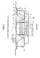
speaker device 100 according to an embodiment of the present invention, a front view of thespeaker device 100 as seen from the front side (acoustic radiation side). - Fig. 2
- is a sectional view of the
speaker device 100 shown inFig. 1 , taken along the line A-A. - Fig. 3
- is a sectional view for explaining a
speaker device 100a according to another embodiment of the present invention. - Figs. 4(A) to 4(C)
- are diagrams for explaining a diaphragm of the
speaker device 100 shown inFig. 1 , - Fig. 4(A)
- being a sectional view for explaining a concrete example of the cross-sectional shape of the diaphragm of the
speaker device 100, - Fig. 4(B)
- being a sectional view for explaining another concrete example of the cross-sectional shape of the diaphragm of the
speaker device 100, - Fig. 4(C)
- being a diagram for explaining the cross-sectional shape of the diaphragm shown in
Fig. 4(A) in detail. - Figs. 5(A) and 5(B)
- are diagrams for explaining the results of simulation on the magnetic flux density in magnetic circuits.
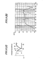
- Fig. 6
- is a chart for explaining the distribution of the magnetic flux density in the magnetic gaps 4g of the
magnetic circuits 4 shown inFigs. 5(A) and 5(B) . - Fig. 7(A)
- is a diagram showing a diaphragm to be compared in which an
inner diaphragm portion 81 is formed with a cross section of generally straight shape and anouter diaphragm portion 82 is formed with a cross section of concave shape to the acoustic radiation side, and - Fig. 7(B)
- is a chart showing the result of simulation on the sound pressure level of the speaker device which uses the diaphragm shown in
Fig. 7(A) . - Fig. 8(A)
- is a diagram showing a diaphragm in which the
inner diaphragm portion 81 is formed with a cross section of convex shape and theouter diaphragm portion 82 is formed with a cross section of convex shape toward the acoustic radiation side, and - Fig. 8(B)
- is a chart showing the result of simulation on the sound pressure level of the speaker device which uses the diaphragm shown in
Fig. 8(A) . - Fig. 9(A)
- is a diagram showing a diaphragm in which the
inner diaphragm portion 81 is formed with a cross section of convex shape and theouter diaphragm portion 82 is formed with a cross section of generally straight shape, and - Fig. 9(B)
- is a chart showing the result of simulation on the sound pressure level of the speaker device which uses the diaphragm shown in
Fig. 9(A) . - Fig. 10(A)
- is a diagram showing a diaphragm in which the
inner diaphragm portion 81 is formed with a cross section of generally straight shape and theouter diaphragm portion 82 is formed with a cross section of generally straight shape, theinner diaphragm portion 81 having a length A (r81) greater than the length B (r82) of theouter diaphragm portion 82, and - Fig. 10(B)
- is a chart showing the result of simulation on the sound pressure level of the speaker device which uses the diaphragm shown in
Fig. 10(A) . - Fig. 11(A)
- is a diagram showing a diaphragm in which the
inner diaphragm portion 81 is formed with a cross section of generally straight shape and theouter diaphragm portion 82 is formed with a cross section of generally straight shape, theinner diaphragm portion 81 having the same length A (r81) as the length B (r82) of theouter diaphragm portion 82, and - Fig. 11(B)
- is a chart showing the result of simulation on the sound pressure level of the speaker device which uses the diaphragm shown in
Fig. 11(A) . - Fig. 12(A)
- is a diagram showing a diaphragm in which the
inner diaphragm portion 81 is formed with a cross section of generally straight shape and theouter diaphragm portion 82 is formed with a cross section of generally straight shape, theinner diaphragm portion 81 having a length A (r81) smaller than the length B (r82) of theouter diaphragm portion 82, and - Fig. 12(B)
- is a chart showing the result of simulation on the sound pressure level of the speaker device which uses the diaphragm shown in
Fig. 12(A) . - Fig. 13(A)
- is a diagram showing a diaphragm in which the
inner diaphragm portion 81 is formed with a cross section of generally straight shape and theouter diaphragm portion 82 is formed with a cross section of generally straight shape, the outer rim of the diaphragm being formed with a diameter (outer diameter) 4.8 times the height d8 of the outer rim of the diaphragm, and - Fig. 13(B)
- is a chart showing the result of simulation on the sound pressure level of the speaker device which uses the diaphragm shown in
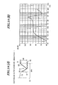
Fig. 13(A) . - Fig. 14(A)
- is a diagram showing a diaphragm in which the
inner diaphragm portion 81 is formed with a cross section of generally straight shape and theouter diaphragm portion 82 is formed with a cross section of generally straight shape, the outer rim of the diaphragm having a diameter (outer diameter) 3.8 times the height d8 of the outer rim of the diaphragm, and - Fig. 14(B)
- is a chart showing the result of simulation on the sound pressure level of the speaker device which uses the diaphragm shown in
Fig. 14(A) . - Fig. 15(A)
- is a diagram showing a diaphragm in which the
inner diaphragm portion 81 is formed with a cross section of generally straight shape and theouter diaphragm portion 82 is formed with a cross section of generally straight shape, the outer rim of the diaphragm having a diameter (outer diameter) 3.2 times the height d8 of the outer rim of the diaphragm, and - Fig. 15(B)
- is a chart showing the result of simulation on the sound pressure level of the speaker device which uses the diaphragm shown in
Fig. 15(A) . - A speaker device according to an embodiment of the present invention includes: a diaphragm having an inner rim connected to a voice coil bobbin and an outer rim connected to a frame through an edge, the diaphragm being shaped so that a peak portion thereof is formed between the inner rim and the outer rim which are positioned at an acoustic radiation side in comparison with the peak portion; and an inner magnet type magnetic circuit for driving a voice coil arranged on the voice coil bobbin.
In the speaker device of the above configuration, the inner magnet type magnetic circuit drives the diaphragm of the foregoing shape through the voice coil and the voice coil bobbin. As compared to conventional speaker devices in which the diaphragm is driven by using, for example, an outer magnet type magnetic circuit, the speaker device can thus be made smaller in profile. - Hereinafter, a speaker device according to the embodiment of the present invention will be described with reference to the drawings.
-
Fig. 1 is a diagram for explaining aspeaker device 100 according to the embodiment of the present invention. More specifically,Fig. 1 is a front view of thespeaker device 100 as seen from the front side (acoustic radiation side).Fig. 2 is a sectional view of thespeaker device 100 shown inFig. 1 , taken along the line A-A.Fig. 3 is a sectional view for explaining aspeaker device 100a according to another embodiment of the present invention. - The
speaker device 100 includes: an inner magnet typemagnetic circuit 4 including ayoke 1,plates 2, andmagnets 3; a frame (speaker frame) 5; avoice coil 7 wound and arranged around avoice coil bobbin 6; adiaphragm 8; anedge 9; adamper 10; acenter cap unit 11; and leads 12. - The inner magnet type
magnetic circuit 4 corresponds to an embodiment of the inner magnet type magnetic circuit of a speaker device according to the present invention. Thediaphragm 8 corresponds to an embodiment of the diaphragm of a speaker device according to the present invention. Theyoke 1 corresponds to an embodiment of the yoke of a speaker device according to the present invention. Theframe 5 corresponds to an embodiment of the frame of a speaker device according to the present invention. - The
magnetic circuit 4 of a speaker device according to the present embodiment includes theyoke 1, the two magnets 3 (31, 32), and the two plates 2 (21, 22). The plate 2 (21) is also referred to as a center plate. - The
yoke 1 has abottom portion 1a which is connected to the bottom of the magnet 3 (3 1), and aside portion 1b which is shaped so as to spread out radially from thisbottom portion 1a, bend to the direction of acoustic radiation (front), and extend from thebend 1c to beside the plate 2 (21). Thebottom portion 1a and theside portion 1b of theyoke 1 are formed integrally with each other. Theyoke 1 of a speaker device according to the present embodiment has aslope portion 1d which is formed on the outer corner of the end of theside portion 1 b at the acoustic radiation side. Ahole portion 1h is formed in the center of theyoke 1. Theyoke 1 may be made of such materials as inorganic materials, metals, iron, and other magnetic materials. - In the
magnetic circuit 4, as shown inFig. 2 , the plate 2 (21) is arranged between the magnet 3 (31) and the magnet 3 (32), and the plate 2 (22) is arranged on the magnet 3 (32). The magnets 3 (31, 32) are arranged so that the same poles are opposed to each other. Themagnetic circuit 4 of such a configuration is referred to as repulsion magnetic circuit. The use of the repulsion magnetic circuit provides the effects of creating a relatively high magnetic flux density in the magnetic gap 4g, providing increased sensitivity, and so on.
The magnets 3 (31, 32) may be made of materials such as permanent magnets including neodymium type, samarium-cobalt type, alnico type, and ferrite type magnets. The plates 2 (21, 22) may be made of materials such as iron and other metals, and magnetic materials. - In the
magnetic circuit 4 of a speaker device according to the present embodiment, theyoke 1, the magnet 3 (31), the plate 2 (21), the magnet 3 (32), and the plate 2 (22) are formed concentrically with respect to the center axis O. More specifically, they are closely arranged on the same axis, at overlapping positions along the direction of the center axis O. - The magnet 3 (31), the plate 2 (21), the magnet 3 (32), and the plate 2 (22) may be formed in a ring shape. The
magnetic circuit 4 may be a radial magnetic circuit having so-called radial ring magnets, in which the magnets 3 (31, 32) of the foregoing configuration are magnetized so that the same poles are opposed to each other along the thickness direction (the direction of vibration). This creates a magnetic gap between the inner and outer sides of the magnets 3 (31, 32) so that the flowing direction of the magnetic fluxes coincides with the direction of the magnetic fluxes which flow inside themagnetic circuit 4. The use of the radial magnetic circuit for themagnetic circuit 4 provides the effects of allowing improved magnetic efficiency, allowing lower profile, allowing miniaturization, and the like. - The
magnetic circuit 4 according to the present embodiment can also reduce magnetic leakage because of the structure that the magnet 3 (31) is surrounded by theyoke 1 which is made of iron or the like. - As shown in
Fig. 2 , themagnetic circuit 4 has the magnetic gap 4g for driving thevoice coil 7. The magnetic fluxes caused by the magnets 3 (31, 32) are concentrated to this magnetic gap 4g. More specifically, the magnetic gap 4g is formed between the inner periphery of theside portion 1b of theyoke 1 and the outer periphery of the plate 2 (21), with a generally uniform interval across the entire circumference. - As described above, the
magnetic circuit 4 of a speaker device according to the present embodiment uses a so-called repulsion magnetic circuit, having the two magnets 3 (31, 32) arranged with the same poles opposed to each other, whereas it is not limited to this configuration. For example, as shown inFig. 3 , aspeaker device 100a may have amagnetic circuit 4a which is configured so that the magnet 3 (31) is arranged on apole portion 1a of theyoke 1, and the plate 2 (21) is arranged on the magnet 3 (31). Because of the provision of themagnetic circuit 4a which consists of theyoke 1, the plate 2 (21), and the magnet 3 (31), thespeaker device 100a according to the configuration shown inFig. 3 has the effects of allowing lower profile, allowing smaller size, and the like. - As shown in
Figs. 1 and2 , theframe 5 has a rear flat portion (bottom portion) 51, on the center of which themagnetic circuit 4 is arranged. Anopening 5a is formed in the center of the rearflat portion 51. Theframe 5 has a cone-shapedportion 52 which is formed to bend from the outer rim of the rearflat portion 51 to the acoustic radiation side. Aflat portion 53 for anouter rim 10a of thedamper 10 to be fixed to is formed in the middle of the cone-shapedportion 52 of theframe 5. Aflat portion 54 for anouter rim 9a of theedge 9 to be fixed to, either directly or through ajoint member 90, is formed near the top of the cone-shapedportion 52 on the front side. Aflange 55 is formed on the outer periphery of theframe 5. The cone-shapedportion 52 has one ormore window portions 52a andarm portions 52b between theflat portions - In the
frame 5 of a speaker device according to the present embodiment, the rearflat portion 51, the cone-shapedportion 52, theflat portion 53, theflat portion 54, and theflange 55 are formed integrally with each other. - The
voice coil 7 is formed, for example, by winding an electric wire around thevoice coil bobbin 6 of cylindrical shape, and is fixed to thevoice coil bobbin 6. At least part of thevoice coil 7 is arranged in the magnetic gap 4g of themagnetic circuit 4 so as to be capable of vibrations. - The
center cap unit 11 is formed with an outer diameter generally the same as the inner diameter of thevoice coil bobbin 6, for example. Thecenter cap unit 11 is firmly fixed to thevoice coil bobbin 6 with an adhesive or the like, thereby being connected with thevoice coil bobbin 6. Thecenter cap unit 11 of a speaker device according to the present embodiment is formed in a convex shape toward the acoustic radiation side. Thecenter cap unit 11 is not limited to a particular shape, and may be formed in a concave shape in order to reduce the speaker device in profile. - The
diaphragm 8 may be made of various materials such as resin and other polymer materials, paper materials, and metal materials. Thediaphragm 8 has a ring-like acoustic radiation surface which extends from aninner rim 8a to anouter rim 8b. Theinner rim 8a has a center hole portion for establishing connection with thevoice coil bobbin 6. Thevoice coil bobbin 6 is fit into the center hole portion of thediaphragm 8 and firmly fixed with an adhesive or the like, whereby theinner rim 8a of thediaphragm 8 is connected to near the end of thevoice coil bobbin 6 on the acoustic radiation side. Theouter rim 8b of thediaphragm 8 is attached to theframe 5 through theedge 9. - The
edge 9 is formed in a ring shape, for example. Various edges may be employed for theedge 9, including a roll edge, V edge, corrugation edge, and flat edge. For theedge 9 of a speaker device according to the present embodiment, a roll edge is employed. Theedge 9 has both appropriate compliance and rigidity, and theinner rim 9b of theedge 9 is firmly fixed to theouter rim 8b of thediaphragm 8 with an adhesive or the like so that theedge 9 is connected with thediaphragm 8. - As described above, the
outer rim 9a of theedge 9 is firmly fixed to theflat portion 54 of theframe 5 directly or through thejoint member 90, thereby being connected with theframe 5. Theouter rim 8b of thediaphragm 8 is thus connected to theframe 5 through theedge 9. Theedge 9 thereby supports the outer rim of thediaphragm 8 elastically. - As shown in
Figs. 1 and2 , thediaphragm 8 is shaped so that apeak portion 8c is formed between theinner rim 8a and theouter rim 8b, and theinner rim 8a and theouter rim 8b are positioned at the acoustic radiation side in comparison with thepeak portion 8c. Thepeak portion 8c of thediaphragm 8 is fixed to aninner rim 10b of thedamper 10 with an adhesive or the like. - The
damper 10 is formed, for example, by immersing a cloth into resin, followed by heat forming. Various shapes of dampers may be used for thedamper 10, including a concentrically-corrugated circular damper. Thedamper 10 has both appropriate compliance and rigidity. Theouter rim 10a of thedamper 10 is connected to theframe 5, and thepeak portion 8c of thediaphragm 8 is supported by theinner rim 10b.
As shown inFig. 2 , theinner rim 10b of thedamper 10 of a speaker device according to the present embodiment is shaped so as to bend toward the acoustic radiation side and along the inclined surface of thediaphragm 8 as well, and is fixed to thepeak portion 8c with an adhesive or the like. Theinner rim 10b of thedamper 10 and thepeak portion 8c of thediaphragm 8 are therefore fixed to each other with reliability.
As shown inFigs. 1 and2 , thespeaker device 100 is also formed so that thedamper 10, theflat portion 53 of theflame 5, thevoice coil 7, the plate 2 (21), and thepeak portion 8c of thediaphragm 8 are generally flush with each other. - In the
speaker device 100 of the foregoing configuration, thepeak portion 8c of thediaphragm 8 is set to the height of thedamper 10. This can reduce variations in the height of thepeak portion 8c of thediaphragm 8, thereby allowing high-quality sound reproduction. Setting thepeak portion 8c of thediaphragm 8 to the height of thedamper 10 also improves assembly workability. - The
damper 10 of the foregoing configuration elastically supports thediaphragm 8, thecenter cap unit 11, thevoice coil bobbin 6, and thevoice coil 7 with theedge 9 at predetermined positions in the speaker when the speaker is not driven. Thevoice coil 7 and thevoice coil bobbin 6 arranged in the magnetic gap 4g are also elastically retained in positions not in contact with the components of themagnetic circuit 4, such as theside portion 1b of theyoke 1.
Thedamper 10 also has the function of elastically supporting thecenter cap unit 11, thediaphragm 8, thevoice coil bobbin 6, and thevoice coil 7 along the direction of vibration (the direction of the center axis (O)) when the speaker is driven.
As described above, theyoke 1 has theslope portion 1d which is formed on the outer corner of the end of theside portion 1b at the acoustic radiation side. This can prevent thediaphragm 8 from coming into contact with theyoke 1 even when the speaker is driven and thediaphragm 8 vibrates along the direction of vibration (the direction of the center axis (O)). - Both ends of the
voice coil 7 are extending along thevoice coil bobbin 6 and thediaphragm 8, and electrically connected with a respective pair ofleads 12, for example, near the inner rim of thediaphragm 8 as shown inFig. 1 .
The leads 12 are lead wires made of strands of a plurality of fine wires, for example, and have a high bending strength. The leads 12 are connected to aninput terminal unit 14 which is fixed to theframe 5, throughholes 13 which are formed in thediaphragm 8. - In the
speaker device 100 of the foregoing configuration, when a sound signal is input to theinput terminal unit 14, an electric current corresponding to the sound signal is supplied to thevoice coil bobbin 6 through the leads 12. As a result, thevoice coil bobbin 6 is electromagnetically driven in the magnetic gap 4g. Being supported by theedge 9 and thedamper 10, thecenter cap unit 11 and thediaphragm 8 connected with thevoice coil bobbin 6 are driven along the direction of piston vibrations, whereby acoustic energy corresponding to the sound signal is radiated from thediaphragm 8. -
Figs. 4(A) to 4(C) are diagrams for explaining the diaphragm of thespeaker device 100 shown inFig. 1 . More specifically,Fig. 4(A) is a sectional view for explaining a concrete example of the cross-sectional shape of thediaphragm device 100.Fig. 4(B) is a sectional view for explaining another concrete example of the cross-sectional shape of thediaphragm device 100.Fig. 4(C) is a diagram for explaining the cross-sectional shape of the diaphragm shown inFig. 4(A) in detail. - In order to suppress the overall height of the
speaker device 100, to suppress divided vibration of thediaphragm 8 when driven, and to improve the sound pressure level at high frequencies, thediaphragm 8 of a speaker device according to the present embodiment has the following structure.
That is, as shown inFigs. 1 ,2 , and4(A) to 4(C), thediaphragm 8 is formed to have a fold between theinner rim 8a and theouter rim 8b, with this fold as thepeak portion 8c.
Thispeak portion 8c is the top area of the fold of thediaphragm 8, being folded back at an acute angle so that theinner rim 8a and theouter rim 8b are positioned at the acoustic radiation side in comparison with the peak portion 8C. - For example, as shown in
Figs. 4(A) to 4(C) , thediaphragm 8 has aninner diaphragm portion 81 which is formed on the side of theinner rim 8a with respect to thepeak portion 8c of thediaphragm 8, and anouter diaphragm portion 82 which is formed on the side of theouter rim 8b with respect to thepeak portion 8c of thediaphragm 8. Theinner diaphragm portion 81 and theouter diaphragm portion 82 are formed integrally with each other. - More specifically, as shown in
Fig. 4(A) , theinner diaphragm portion 81 on the side of theinner rim 8a with respect to thepeak portion 8c of thediaphragm 8 is formed with a cross section of convex shape toward the acoustic radiation side. Theouter diaphragm portion 82 on the side of theouter rim 8b with respect to thepeak portion 8c of thediaphragm 8 is formed with a cross section of convex shape toward the acoustic radiation side. - As shown in
Fig. 4(B) , theinner diaphragm portion 81 of thediaphragm 8 may be formed with a cross section of convex shape toward the acoustic radiation side while theouter diaphragm portion 82a may be formed with a cross section of generally straight shape. - As shown in
Fig. 4(C) , thepeak portion 8c of thediaphragm 8 has a diameter ϕa which is smaller than the diameter ϕb of theouter rim 8b of thediaphragm 8. The diameter ϕa of thepeak portion 8c is greater than the diameter ϕc of thevoice coil bobbin 6.
As shown inFig. 4(C) , thediaphragm 8 of a speaker device according to the present embodiment is desirably formed so that the radial length r81 from theinner rim 8a to thepeak portion 8c is smaller than the radial length r82 from thepeak portion 8c to theouter rim 8b. - In the
diaphragm 8 of a speaker device according to the present embodiment, as shown inFig. 4(C) , theouter rim 8b of thediaphragm 8 desirably has a diameter ϕb no greater than four times the height d8 of theouter rim 8b of thediaphragm 8. The height d8 of theouter rim 8b of thisdiaphragm 8 refers to the distance from thepeak portion 8c of thediaphragm 8 to theouter rim 8b of thediaphragm 8 along the direction of acoustic radiation. - In the
speaker device 100 of the foregoing configuration, the diaphragm extending from theinner rim 8a to theouter rim 8b is folded back at thepeak portion 8c. Then, the overall height of thediaphragm 8 is the height from thepeak portion 8c to theinner rim 8a or theouter rim 8b. The overall height of thediaphragm 8 can thus be made smaller than that of a conventional cone-shaped diaphragm which has the same grille diameter (diaphragm diameter) and the same voice coil diameter (theinner rim 8a of the diaphragm 8).
Moreover, in thediaphragm 8 of a speaker device according to the present embodiment, thepeak portion 8c of thediaphragm 8 is optimized in diameter ϕa with respect to the diameter ϕb of theouter rim 8b of thediaphragm 8. Theinner diaphragm portion 81 is formed in a convex shape, and theouter diaphragm portion 82 is formed with a cross section of convex shape or generally straight shape. Theouter rim 8b of thediaphragm 8 is optimized in diameter ϕb and height d8. Such conditions make it possible to improve the reproduction frequency characteristic at high frequencies.
Thediaphragm 8 may be formed under any one of the foregoing conditions, two conditions in combination, or the three conditions in combination, with the effect of improving the reproduction frequency characteristic at high frequencies. - That is, the
speaker device 100 according to the present embodiment can provide the effects of reducing the speaker device heretofore in size, in profile, and in weight, and can reproduce sound in high quality as well. - Next, the inventor performed a computer-based simulation on the distribution of magnetic flux densities in the
magnetic circuit 4, in order to confirm the performance of themagnetic circuit 4 of thespeaker device 100 according to the embodiment of the present invention. -
Figs. 5(A) and 5(B) are diagrams for explaining the results of simulation on the magnetic flux density in magnetic circuits. More specifically,Fig. 5(A) is a diagram showing the distribution of magnetic fluxes in a magnetic circuit in which the yoke end has no slope portion.Fig. 5(B) is a diagram showing the distribution of magnetic fluxes in a magnetic circuit in which the yoke end has a slope portion. -
Fig. 6 is a chart for explaining the magnitude of the magnetic flux density in the magnetic gaps 4g of themagnetic circuits 4 shown inFigs. 5(A) and 5(B) . The vertical axis of this chart indicates the magnitude of the magnetic flux density (T: Tesla), and the horizontal axis indicates the position in the magnetic gap along the direction of vibration (mm). InFig. 6 , the dotted line represents the magnitude of the magnetic flux density in themagnetic circuit 4 having the structure shown inFig. 5(A) . - The full line represents the magnitude of the magnetic flux density in the
magnetic circuit 4 having the structure shown inFig. 5(B) . InFig. 6 , 0 mm corresponds to the vicinity of the boundary between thecenter plate 2 and the magnet 3 (31), 2 mm corresponds to the vicinity of the center of thecenter plate center plate 2 and the magnet 3 (32). - As shown in
Fig. 5(A) , it is confirmed that the magnetic fluxes concentrate on near the ends of the plate 2 (21) which is sandwiched between the magnet 3 (31) and the magnet 3 (32). It is also confirmed that magnetic leakage is prevented by theside portion 1b of theyoke 1. The use of this repulsion magnetic circuit allows a relatively high magnetic flux density in the magnetic gap 4g. - Moreover, as shown in
Fig. 5(B) , it is confirmed that themagnetic circuit 4 having theslope portion 1d at the end of theside portion 1b of theyoke 1 creates an improved flow of magnetic fluxes near theslope portion 1d as compared to the magnetic circuit shown inFig. 5(A) . It was also confirmed that the magnetic fluxes continue to flow near the ends of the magnet 3 (31) without closing up. - As shown in
Fig. 6 , it was confirmed that themagnetic circuits 4 reach the maximum values of the magnetic flux density (approximately 1.04 T) in the vicinity of the center (around 2 mm) of the center plate 2 (21), and the magnetic flux density is generally uniform in magnitude across around ± 1 mm about the center. It was also confirmed that the magnetic flux density increases in magnitude when theslope portion 1d is formed on the end of theside portion 1b of theyoke 1 as shown by the full line, when compared to the case where noslope portion 1d is formed on the end of theside portion 1b of theyoke 1 as shown by the dotted line. - As described above, the
magnetic circuit 4 may have theslope portion 1 d on the end of theside portion 1b of theyoke 1. This can make the magnetic flux density in the magnetic gap 4g of themagnetic circuit 4 greater in magnitude.
As described above, since theslope portion 1d is formed on the outer corner of the end of theside portion 1b of theyoke 1 at the acoustic radiation side, thediaphragm 8 can also be prevented from coming into contact with theyoke 1 even when the speaker is driven and thediaphragm 8 vibrates along the direction of vibration (the direction of the center axis (O)). - Next, in order to confirm the performance of the diaphragm of the
speaker device 100 according to the embodiment of the present invention, the inventor made a study on diaphragms of different cross-sectional shapes and performed a simulation on the sound pressure levels (SPL) of speaker devices using those diaphragms.Figs. 7 to 15 are diagrams showing the cross-sectional shapes of the diaphragms and the results of simulation on the sound pressure levels of the speaker devices using those diaphragms. Hereinafter, the sound pressure levels of the speakers will be described with reference to the diagrams. -
Fig. 7(A) is a diagram showing a diaphragm to be compared in which theinner diaphragm portion 81 is formed with a cross section of generally straight shape and theouter diaphragm portion 82 is formed with a cross section of concave shape to the acoustic radiation side.Fig. 7(B) is a chart showing the result of simulation on the sound pressure level of the speaker device which uses the diaphragm shown inFig. 7(A) . -
Fig. 8(A) is a diagram showing a diaphragm in which theinner diaphragm portion 81 is formed with a cross section of convex shape and theouter diaphragm portion 82 is formed with a cross section of convex shape toward the acoustic radiation side.Fig. 8(B) is a chart showing the result of simulation on the sound pressure level of the speaker device which uses the diaphragm shown inFig. 8(A) . -
Fig. 9(A) is a diagram showing a diaphragm in which theinner diaphragm portion 81 is formed with a cross section of convex shape and theouter diaphragm portion 82 is formed with a cross section of generally straight shape.Fig. 9(B) is a chart showing the result of simulation on the sound pressure level of the speaker device which uses the diaphragm shown inFig. 9(A) . - Initially, take the diaphragm to be compared in which the
inner diaphragm portion 81 is formed with a cross section of generally straight shape and theouter diaphragm portion 82 is formed with a cross section of concave shape to the acoustic radiation side as shown inFig. 7(A) . As shown inFig. 7(B) , the sound pressure level is approximately 60 dB at frequencies of around 30 Hz.
The sound pressure level increases from 30 Hz to 200 Hz to reach 85 dB at 200 Hz, shows a generally flat characteristic from 200 Hz to 1 kHz, and increases sharply from 1 kHz to reach a maximum value of approximately 97 dB at around 3 kHz. The sound pressure level then drops sharply from 3 kHz to 5 kHz to reach approximately 67 Hz at 5 kHz, increases from 5 kHz to 20 kHz, and shows a value of 75 dB at 20 kHz. - Now, take the
diaphragm 8 according to the present invention in which theinner diaphragm portion 81 is formed with a cross section of convex shape and theouter diaphragm portion 82 is formed with a cross section of convex shape toward the acoustic radiation side as shown inFig. 8(A) . - As shown in
Fig. 8(B) , the sound pressure level is approximately 60 dB at frequencies of around 30 Hz. The sound pressure level increases from 30 Hz to 200 Hz to reach 85 dB at 200 Hz, shows a generally flat characteristic from 200 Hz to 1 kHz, and increases from 1 kHz to reach a peak value of approximately 91 dB at around 4 kHz, followed by a decrease. The sound pressure level then reaches a peak value of approximately 91 dB at around 7 kHz, then decreases to 65 dB at approximately 15 kHz, increases from approximately 15 kHz to 20 kHz, and shows a value of 75 dB at 20 kHz. - As described above, it was confirmed that the
diaphragm 8 according to the present invention shown inFig. 8(A) has an improved frequency characteristic at high frequencies (for example, from approximately 3 kHz to 10 kHz or so) as compared to the comparative example shown inFig. 7(A) . - Now, take the
diaphragm 8 according to the present invention in which theinner diaphragm portion 81 is formed with a cross section of convex shape and theouter diaphragm portion 82 is formed with a cross section of generally straight shape to the acoustic radiation side as shown inFig. 9(A) . As shown inFig. 9(B) , the sound pressure level is approximately 60 dB at frequencies of around 30 Hz.
The sound pressure level increases from 30 Hz to 200 Hz to reach 85 dB at 200 Hz, shows a generally flat characteristic from 200 Hz to 1 kHz, and increases from 1 kHz to reach a peak value of approximately 95 dB at around 4.5 kHz. The sound pressure level then drops to 60 dB or less at around 11 kHz, and increases from approximately 11 kHz to 20 kHz to reach a value of 75 dB at 20 kHz.
As described above, it was confirmed that thediaphragm 8 according to the present invention shown inFig. 9(A) has an improved frequency characteristic at high frequencies (for example, from approximately 3 kHz to 10 kHz or so) as compared to the comparative example shown inFig. 7 . -
Fig. 10(A) is a diagram showing a diaphragm in which theinner diaphragm portion 81 is formed with a cross section of generally straight shape and theouter diaphragm portion 82 is formed with a cross section of generally straight shape, theinner diaphragm portion 81 having a length A (r81) greater than the length B (r82) of theouter diaphragm portion 82.Fig. 10(B) is a chart showing the result of simulation on the sound pressure level of the speaker device which uses the diaphragm shown inFig. 10(A) . -
Fig. 11 (A) is a diagram showing a diaphragm in which theinner diaphragm portion 81 is formed with a cross section of generally straight shape and theouter diaphragm portion 82 is formed with a cross section of generally straight shape, theinner diaphragm portion 81 having the same length A (r81) as the length B (r82) of theouter diaphragm portion 82.Fig. 11(B) is a chart showing the result of simulation on the sound pressure level of the speaker device which uses the diaphragm shown inFig. 11 (A) . -
Fig. 12(A) is a diagram showing a diaphragm in which theinner diaphragm portion 81 is formed with a cross section of generally straight shape and theouter diaphragm portion 82 is formed with a cross section of generally straight shape, theinner diaphragm portion 81 having a length A (r81) smaller than the length B (r82) of theouter diaphragm portion 82.Fig. 12(B) is a chart showing the result of simulation on the sound pressure level of the speaker device which uses the diaphragm shown inFig. 12(A) . - Next, as shown in
Figs. 10(A) and10(B) to 12(A) and12(B) , the length A (r81) of theinner diaphragm portion 81 and the length B (r82) of theouter diaphragm portion 82 are optimized.
As shown inFig. 12(B) , it was confirmed that the high-frequency characteristic is improved when using the diaphragm in which theinner diaphragm portion 81 has a length A (r81) smaller than the length B (r82) of theouter diaphragm portion 82, as compared to the other cases. That is, thediaphragm 8 according to the present invention preferably uses one in which the length A (r81) of theinner diaphragm portion 81 is smaller than the length B (r82) of theouter diaphragm portion 82. -
Fig. 13(A) is a diagram showing a diaphragm in which theinner diaphragm portion 81 is formed with a cross section of generally straight shape and theouter diaphragm portion 82 is formed with a cross section of generally straight shape, the outer rim of the diaphragm being formed with a diameter (outer diameter) 4.8 times the height d8 of the outer rim of the diaphragm.Fig. 13(B) is a chart showing the result of simulation on the sound pressure level of the speaker device which uses the diaphragm shown inFig. 13(A) . -
Fig. 14(A) is a diagram showing a diaphragm in which theinner diaphragm portion 81 is formed with a cross section of generally straight shape and theouter diaphragm portion 82 is formed with a cross section of generally straight shape, the outer rim of the diaphragm being formed with a diameter (outer diameter) 3.8 times the height d8 of the outer rim of the diaphragm.Fig. 14(B) is a chart showing the result of simulation on the sound pressure level of the speaker device which uses the diaphragm shown inFig. 14(A) . -
Fig. 15(A) is a diagram showing a diaphragm in which theinner diaphragm portion 81 is formed with a cross section of convex shape and theouter diaphragm portion 82 is formed with a cross section of generally straight shape, the outer rim of the diaphragm being formed with a diameter (outer diameter) 3.2 times the height d8 of the outer rim of the diaphragm.Fig. 15(B) is a chart showing the result of simulation on the sound pressure level of the speaker device which uses the diaphragm shown inFig. 15(A) . - Next, as shown in
Figs. 13(A) and13(B) to 15(A) and15(B), the outer diameter and the height of the diaphragm are optimized.
As shown inFig. 13(A) , when theinner diaphragm portion 81 is formed with a cross section of generally straight shape and theouter diaphragm portion 82 is formed with a cross section of generally straight shape, and the outer rim of the diaphragm is formed with a diameter (outer diameter) 4.8 times the height d8 of the outer rim of the diaphragm, the diaphragm has a deteriorated high-frequency characteristic as compared to the other cases as shown inFig. 13(B) .
On the other hand, when the outer rim of thediaphragm 8 is formed with a diameter (outer diameter) 3.8 times or 3.2 times the height d8 of the outer rim of the diaphragm as shown inFigs. 14(A) and15(A) , the diaphragms have an improved high-frequency characteristic as compared to the other case.
It is therefore desirable to use adiaphragm 8 which is shaped, for example, so that the diameter (outer diameter) of the outer rim of thediaphragm 8 is smaller than or equal to approximately four times the height d8 of the outer rim of the diaphragm, or smaller than or equal to approximately 3.8 times or 3.2 times in particular. - As has been described, the
speaker device 100 according to the present invention includes: thediaphragm 8 which has theinner rim 8a connected to thevoice coil bobbin 6 and theouter rim 8b connected to theframe 5 through theedge 9, and is shaped so that thepeak portion 8c is formed between theinner rim 8a and theouter rim 8b, which are positioned at an acoustic radiation side in comparison with thepeak portion 8c; and the inner magnet typemagnetic circuit 4 for driving thevoice coil 7 which is arranged on thevoice coil bobbin 6 connected to theinner rim 8a of thediaphragm 8. As compared to, for example, a magnetic circuit of outer magnet type, thespeaker device 100 according to the present invention can thus be made smaller than heretofore in size, in profile, and in weight since the speaker device has themagnets 3 in its center.
The use of the repulsion magnetic circuit improves the magnetic efficiency, which allows high-quality sound reproduction. - The inner magnet type
magnetic circuit 4 includes: the magnet 3 (31); the plate 2 (21) which is arranged on the magnet 3 (31); and theyoke 1 which is shaped to spread out radially from thebottom portion 1a connected to the bottom of the magnet 3 (31), bend to the direction of acoustic radiation, and extend to beside the plate 2 (21). The structure that the magnet 3 (31) is surrounded with theyoke 1 and theframe 5 made of an iron material or the like can prevent magnetic leakage.
Theyoke 1 and theframe 5 for preventing magnetic leakage can also be reduced in thickness. This translates into a lighter weight. - The
outer rim 10a of thedamper 10 is connected to theframe 5, and thepeak portion 8c of thediaphragm 8 is supported by theinner rim 10b of this damper. Thedamper 10 can thus support thepeak portion 8c of thediaphragm 8 so as to be capable of vibrations. Since thepeak portion 8c of thediaphragm 8 is set to the height of thedamper 10, it is possible to reduce variations in the height of thepeak portion 8c of thediaphragm 8, thereby allowing high-quality sound reproduction. Setting thepeak portion 8c of thediaphragm 8 to the height of thedamper 10 also improves assembly workability. - Since the inner magnet type
magnetic circuit 4 uses a repulsion magnetic circuit, thespeaker device 100 can be reduced in size and in profile even with the effects that it is possible to improve the magnetic flux density in the magnetic gap 4g, it is possible to improve the force for driving thediaphragm 8, it is possible to reproduce sound in high quality, and so on. - The
yoke 1 arranged around the inner magnet typemagnetic circuit 4 has theslope portion 1d which is formed on the outer corner of the end of theside portion 1b of theyoke 1 at the acoustic radiation side. It is therefore possible to improve the magnetic flux density in the magnetic gap 4g and improve the force for driving thediaphragm 8 further. - As described above, the
speaker device 100 has the inner magnet typemagnetic circuit 4 which includes the magnet(s) 3, the plate(s) 2, and theyoke 1. Thevoice coil 7 is supported by thevoice coil bobbin 6 and thediaphragm 8 so as to be capable of vibrations in the magnetic gap 4g between the outer periphery of the plate 2 (21) and the inner periphery of theyoke 1. Thevoice coil 7, the plate 2 (21), thepeak portion 8c of thediaphragm 8, and thedamper 10 are formed so as to be generally flush with each other. The end of theside portion 1b of theyoke 1 at the acoustic radiation side is positioned at the acoustic radiation side in comparison with thepeak portion 8c of thediaphragm 8, and theslope portion 1d is formed on the end of theyoke 1. This makes it possible to reduce thespeaker device 100 in size and in profile. - The present invention is not limited to the embodiment described above, but is defined by the scope of the appended claims.
The foregoing embodiment and concrete examples may be combined with each other.
While in the foregoing embodiment themagnetic circuit 4 uses a repulsion magnetic circuit as shown inFig. 2 , it is not limited to this configuration. For example, a magnetic circuit having such a structure as shown inFig. 3 can be used to make the speaker device even smaller in profile and in size.
Claims (13)
- A speaker device comprising:- a frame (5);- a diaphragm (8) having an inner rim (8a) connected to a voice coil bobbin (6) and an outer rim (8b) connected to the frame (5) through an edge (9), the diaphragm being shaped so that a peak portion (8c) thereof is formed between the inner rim (8a) and the outer rim (8b) which are positioned at an acoustic radiation side in comparison with the peak portion (8c);- a damper (10) having an outer rim (10a) connected to the frame (5) on the one hand and an inner rim (10b) supporting the peak portion (8c) of the diaphragm (8) on the other hand; and- an inner magnet type magnetic circuit (4) for driving a voice coil (7)
arranged on the voice coil bobbin (6),
characterized in that
the diaphragm (8) comprises an inner peripheral diaphragm (81) as formed between an inner rim (8a) and the peak portion (8c) of the diaphragm (8) and an outer peripheral diaphragm (82) as formed between the peak portion (8c) and an outer rim (8b) thereof; and
in that the difference between the outer diameter and the inner diameter of the inner peripheral diaphragm (81) is smaller than that of the outer peripheral diaphragm (82). - The speaker device according to claim 1,
wherein the diameter (ϕa) of the peak portion (8c) of the diaphragm (8) is smaller than the diameter (ϕb) of the outer rim (8b) of the diaphragm (8), and is greater than the diameter (ϕc) of the bobbin coil (6). - The speaker device according to claims 1 or 2,
wherein the outer rim (8b) of the diaphragm (8) has a diameter (ϕb) which is not greater than 4 times the height (d8) of the outer rim (8b) of the diaphragm (8),
wherein the height (d8) of the outer rim (8b) is the distance from the peak portion (8c) of the diaphragm (8) to the outer rim (8b) along the direction of acoustic radiation. - The speaker device according to any of claims 1 to 3,
wherein a yoke (1) arranged around the inner magnet type magnetic circuit (4) has a slope portion (1d) formed at an end of the yoke (1). - The speaker device according to any of claims 1to 4,
wherein the inner magnet type magnetic circuit (4) includes a magnet (3), a plate (2) arranged on the magnet (3), and a yoke (1) shaped so as to spread out radially from a bottom portion (1a) connected to a bottom of the magnet (3), and to be provided with a bend (1c) being bent to a direction of acoustic radiation and a side portion (1b) to extend from the bend (1c) to the plate (2);
and
wherein the bend (1c) is smaller in thickness than the bottom portion (1a) or the side portion (1b). - The speaker device according to any of claims 1 to 4,
wherein the inner magnet type magnetic circuit (4) includes a magnet (3), a plate (2) arranged on the magnet (3), and a yoke (1) shaped so as to spread out radially from a bottom portion (1a) connected to a bottom of the magnet (3), and to be provided with a bend (1c) being bent to a direction of acoustic radiation and a side portion (1b) to extend from the bend (1c) to the plate (2); and
wherein the yoke (1) has a step portion formed at a side where the yoke (1) is contacted with the frame (5), the step portion being fitted with an inner periphery of the frame (5). - The speaker device according to claim 6,
wherein the step portion is formed between the bottom portion (1a) and the bend (1c). - The speaker device according to any of claims 5 to 7,
wherein the side portion (1b) is smaller in thickness than the bottom portion (1a). - The speaker device according to any of claims 1 to 8,
wherein the bottom portion (1a) is provided with a hole portion (1h). - The speaker device according to any of claims 1 to 9,
wherein the inner magnet type magnetic circuit (4) is a repulsion magnetic circuit. - The speaker device comprising according to claim 1,
wherein the inner rim (10b) of the damper (10) is shaped so as to bend toward the acoustic radiation side and along the inclined surface of the diaphragm (8), wherein the inner peripheral diaphragm (81) and the outer peripheral diaphragm (82) are formed integrally; and
wherein the peak portion (8c) is the top area of a fold of the diaphragm (8) folded back at an acute angle. - The speaker device according to any of claims 1 to 11,
wherein the inner peripheral diaphragm (81) and the outer peripheral diaphragm (82) are formed with a cross section of convex shape toward the acoustic radiation side. - The speaker device according to any of claims 1 to 12,
wherein the inner magnet type magnetic circuit (4) includes a magnet (3), a plate (2) arranged on the magnet (3), and a yoke (1) having a bottom portion (1a) and a side portion (1b);
wherein the voice coil (7) is supported by the voice coil bobbin (6); wherein the voice coil (6), the plate (2 (21)), and the peak portion (8c) of the diaphragm (8) are formed so as to be generally flush with each other; and
wherein an end of the side portion (1b) of the yoke (1) is positioned at the acoustic radiation side in comparison with the peak portion (8c) of the diaphragm (8).
Applications Claiming Priority (1)
| Application Number | Priority Date | Filing Date | Title |
|---|---|---|---|
| PCT/JP2006/310396 WO2007135745A1 (en) | 2006-05-24 | 2006-05-24 | Speaker device |
Publications (3)
| Publication Number | Publication Date |
|---|---|
| EP2023655A1 EP2023655A1 (en) | 2009-02-11 |
| EP2023655A4 EP2023655A4 (en) | 2010-07-28 |
| EP2023655B1 true EP2023655B1 (en) | 2013-11-13 |
Family
ID=38723061
Family Applications (1)
| Application Number | Title | Priority Date | Filing Date |
|---|---|---|---|
| EP06746825.6A Expired - Fee Related EP2023655B1 (en) | 2006-05-24 | 2006-05-24 | Speaker device |
Country Status (4)
| Country | Link |
|---|---|
| US (1) | US20100208934A1 (en) |
| EP (1) | EP2023655B1 (en) |
| JP (1) | JP4839370B2 (en) |
| WO (1) | WO2007135745A1 (en) |
Families Citing this family (14)
| Publication number | Priority date | Publication date | Assignee | Title |
|---|---|---|---|---|
| EP1989915A1 (en) * | 2006-02-16 | 2008-11-12 | Bang & Olufsen IcePower A/S | A micro-transducer with improved perceived sound quality |
| GB2449842B (en) * | 2007-05-03 | 2012-02-01 | Pss Belgium Nv | Loudspeaker with a stiffening element |
| JP2009200919A (en) * | 2008-02-22 | 2009-09-03 | Pioneer Electronic Corp | Speaker system |
| US8085968B2 (en) * | 2008-07-17 | 2011-12-27 | Bose Corporation | Resonating cone transducer |
| KR200458314Y1 (en) * | 2009-11-06 | 2012-02-24 | 최윤길 | Slimmable type speaker |
| US8428294B2 (en) * | 2010-11-02 | 2013-04-23 | Chun I LIU | Slim speaker |
| CN102118672A (en) * | 2011-03-28 | 2011-07-06 | 苏州上声电子有限公司 | Speaker vibrating diaphragm and speaker |
| EP2806659A4 (en) * | 2012-01-20 | 2015-04-29 | Panasonic Ip Man Co Ltd | Magnetic circuit for a speaker and speaker using same |
| US9232314B2 (en) * | 2013-09-09 | 2016-01-05 | Sonos, Inc. | Loudspeaker configuration |
| JP6194741B2 (en) * | 2013-10-18 | 2017-09-13 | オンキヨー株式会社 | Electrodynamic speaker |
| RU2561341C2 (en) * | 2014-01-17 | 2015-08-27 | Владимир Борисович Комиссаренко | Electroacoustic transducer |
| GB2542382A (en) * | 2015-09-17 | 2017-03-22 | Gp Acoustics (Uk) Ltd | Low-profile loudspeaker |
| US10200802B1 (en) * | 2017-08-03 | 2019-02-05 | Bose Corporation | Inverted button cap in acoustic transducer |
| WO2023166875A1 (en) * | 2022-03-03 | 2023-09-07 | 株式会社Jvcケンウッド | Manufacturing method for speaker diaphragm, speaker diaphragm, and speaker |
Family Cites Families (16)
| Publication number | Priority date | Publication date | Assignee | Title |
|---|---|---|---|---|
| JPS6117674Y2 (en) * | 1978-07-03 | 1986-05-29 | ||
| JPS559170A (en) * | 1978-07-07 | 1980-01-23 | Fujikura Ltd | Surface flaw detector |
| JPH0479700A (en) * | 1990-07-20 | 1992-03-13 | Pioneer Electron Corp | Magnetic circuit for loudspeaker |
| JP3643855B2 (en) * | 1998-06-05 | 2005-04-27 | パイオニア株式会社 | Speaker device |
| US6836551B2 (en) * | 2000-03-23 | 2004-12-28 | Matsushita Electric Industrial Co., Ltd. | Loudspeaker |
| CN1163104C (en) * | 2000-08-24 | 2004-08-18 | 松下电器产业株式会社 | Speaker and magnetic circuit used for the speaker |
| WO2002021880A1 (en) * | 2000-09-04 | 2002-03-14 | Matsushita Electric Industrial Co., Ltd. | Speaker |
| US6607051B1 (en) * | 2000-10-06 | 2003-08-19 | Meiloon Industrial Co., Ltd. | Yoke structure of a speaker diaphragm |
| JP4187939B2 (en) * | 2001-03-06 | 2008-11-26 | パイオニア株式会社 | Magnetic circuit of speaker |
| US7599511B2 (en) * | 2003-08-08 | 2009-10-06 | Pss Belgium N.V. | Loudspeaker with undulated membrane |
| EP1659824A3 (en) * | 2004-11-18 | 2008-02-13 | Pioneer Corporation | Voice coil device and speaker device using the voice coil device |
| JP4706471B2 (en) * | 2005-01-20 | 2011-06-22 | 日本ビクター株式会社 | Diaphragm and electroacoustic transducer |
| JP2006261962A (en) * | 2005-03-16 | 2006-09-28 | Pioneer Electronic Corp | Speaker |
| JP4592500B2 (en) * | 2005-06-02 | 2010-12-01 | パイオニア株式会社 | Speaker device and manufacturing method thereof |
| JP4768824B2 (en) * | 2006-11-17 | 2011-09-07 | パイオニア株式会社 | Speaker device |
| US20100310109A1 (en) * | 2007-09-26 | 2010-12-09 | Pioneer Corporation | Support member for speaker vibrating body and speaker device |
-
2006
- 2006-05-24 JP JP2008516541A patent/JP4839370B2/en not_active Expired - Fee Related
- 2006-05-24 US US12/301,976 patent/US20100208934A1/en not_active Abandoned
- 2006-05-24 WO PCT/JP2006/310396 patent/WO2007135745A1/en active Application Filing
- 2006-05-24 EP EP06746825.6A patent/EP2023655B1/en not_active Expired - Fee Related
Also Published As
| Publication number | Publication date |
|---|---|
| EP2023655A4 (en) | 2010-07-28 |
| JPWO2007135745A1 (en) | 2009-09-24 |
| EP2023655A1 (en) | 2009-02-11 |
| JP4839370B2 (en) | 2011-12-21 |
| US20100208934A1 (en) | 2010-08-19 |
| WO2007135745A1 (en) | 2007-11-29 |
Similar Documents
| Publication | Publication Date | Title |
|---|---|---|
| EP2023655B1 (en) | Speaker device | |
| JPH11355883A (en) | Loudspeaker system | |
| EP2512155B1 (en) | Low profile loudspeaker transducer | |
| US20100177925A1 (en) | Speaker Device | |
| US20090161905A1 (en) | Speaker and magnetic circuit | |
| EP2512154B1 (en) | Loudspeaker magnet having a channel | |
| EP2512153B1 (en) | Loudspeaker magnet assembly | |
| US10694279B1 (en) | Compact coaxial loudspeaker | |
| WO2005086530A1 (en) | Speaker | |
| EP2033482A1 (en) | Speaker | |
| KR20080001090A (en) | Speaker | |
| EP2512156B1 (en) | Low profile loudspeaker | |
| JP5021026B2 (en) | Speaker device | |
| JP4690942B2 (en) | Speaker device manufacturing method and speaker device assembly jig | |
| JP2607796Y2 (en) | Magnetic circuit for speaker | |
| US20180317014A1 (en) | Rear suspension for speaker drivers | |
| EP1737269B1 (en) | Shallow loudspeaker | |
| JP2007318345A (en) | Speaker system | |
| JP2008118331A (en) | Speaker | |
| US20220416634A1 (en) | Separate coil mounting structure of coaxial exciter | |
| JPH11168799A (en) | Loudspeaker device | |
| JP2006129032A (en) | Diaphragm for speaker device and speaker device using the same | |
| JP2605427Y2 (en) | Magnetic circuit for speaker | |
| WO2007042032A2 (en) | Electroacoustic transducer | |
| WO2007077854A1 (en) | Speaker |
Legal Events
| Date | Code | Title | Description |
|---|---|---|---|
| PUAI | Public reference made under article 153(3) epc to a published international application that has entered the european phase |
Free format text: ORIGINAL CODE: 0009012 |
|
| 17P | Request for examination filed |
Effective date: 20081113 |
|
| AK | Designated contracting states |
Kind code of ref document: A1 Designated state(s): AT BE BG CH CY CZ DE DK EE ES FI FR GB GR HU IE IS IT LI LT LU LV MC NL PL PT RO SE SI SK TR |
|
| AX | Request for extension of the european patent |
Extension state: AL BA HR MK YU |
|
| DAX | Request for extension of the european patent (deleted) | ||
| RBV | Designated contracting states (corrected) |
Designated state(s): DE FR GB |
|
| A4 | Supplementary search report drawn up and despatched |
Effective date: 20100628 |
|
| RIC1 | Information provided on ipc code assigned before grant |
Ipc: H04R 9/04 20060101ALI20100622BHEP Ipc: H04R 9/00 20060101AFI20080214BHEP Ipc: H04R 7/12 20060101ALI20100622BHEP Ipc: H04R 9/02 20060101ALI20100622BHEP |
|
| RAP1 | Party data changed (applicant data changed or rights of an application transferred) |
Owner name: TOHOKU PIONEER CORPORATION Owner name: PIONEER CORPORATION |
|
| 17Q | First examination report despatched |
Effective date: 20111129 |
|
| GRAP | Despatch of communication of intention to grant a patent |
Free format text: ORIGINAL CODE: EPIDOSNIGR1 |
|
| INTG | Intention to grant announced |
Effective date: 20130524 |
|
| GRAS | Grant fee paid |
Free format text: ORIGINAL CODE: EPIDOSNIGR3 |
|
| GRAA | (expected) grant |
Free format text: ORIGINAL CODE: 0009210 |
|
| AK | Designated contracting states |
Kind code of ref document: B1 Designated state(s): DE FR GB |
|
| REG | Reference to a national code |
Ref country code: GB Ref legal event code: FG4D |
|
| REG | Reference to a national code |
Ref country code: DE Ref legal event code: R096 Ref document number: 602006039230 Country of ref document: DE Effective date: 20140102 |
|
| REG | Reference to a national code |
Ref country code: DE Ref legal event code: R084 Ref document number: 602006039230 Country of ref document: DE Effective date: 20131022 |
|
| REG | Reference to a national code |
Ref country code: DE Ref legal event code: R097 Ref document number: 602006039230 Country of ref document: DE |
|
| PLBE | No opposition filed within time limit |
Free format text: ORIGINAL CODE: 0009261 |
|
| STAA | Information on the status of an ep patent application or granted ep patent |
Free format text: STATUS: NO OPPOSITION FILED WITHIN TIME LIMIT |
|
| 26N | No opposition filed |
Effective date: 20140814 |
|
| REG | Reference to a national code |
Ref country code: DE Ref legal event code: R097 Ref document number: 602006039230 Country of ref document: DE Effective date: 20140814 |
|
| REG | Reference to a national code |
Ref country code: GB Ref legal event code: 746 Effective date: 20150921 |
|
| REG | Reference to a national code |
Ref country code: FR Ref legal event code: PLFP Year of fee payment: 11 |
|
| REG | Reference to a national code |
Ref country code: FR Ref legal event code: PLFP Year of fee payment: 12 |
|
| REG | Reference to a national code |
Ref country code: FR Ref legal event code: PLFP Year of fee payment: 13 |
|
| PGFP | Annual fee paid to national office [announced via postgrant information from national office to epo] |
Ref country code: DE Payment date: 20190514 Year of fee payment: 14 |
|
| PGFP | Annual fee paid to national office [announced via postgrant information from national office to epo] |
Ref country code: FR Payment date: 20190410 Year of fee payment: 14 |
|
| PGFP | Annual fee paid to national office [announced via postgrant information from national office to epo] |
Ref country code: GB Payment date: 20190522 Year of fee payment: 14 |
|
| REG | Reference to a national code |
Ref country code: DE Ref legal event code: R119 Ref document number: 602006039230 Country of ref document: DE |
|
| GBPC | Gb: european patent ceased through non-payment of renewal fee |
Effective date: 20200524 |
|
| PG25 | Lapsed in a contracting state [announced via postgrant information from national office to epo] |
Ref country code: FR Free format text: LAPSE BECAUSE OF NON-PAYMENT OF DUE FEES Effective date: 20200531 Ref country code: GB Free format text: LAPSE BECAUSE OF NON-PAYMENT OF DUE FEES Effective date: 20200524 |
|
| PG25 | Lapsed in a contracting state [announced via postgrant information from national office to epo] |
Ref country code: DE Free format text: LAPSE BECAUSE OF NON-PAYMENT OF DUE FEES Effective date: 20201201 |