EP2023552B1 - Wireless communication device and wireless communication method - Google Patents
Wireless communication device and wireless communication method Download PDFInfo
- Publication number
- EP2023552B1 EP2023552B1 EP20080013964 EP08013964A EP2023552B1 EP 2023552 B1 EP2023552 B1 EP 2023552B1 EP 20080013964 EP20080013964 EP 20080013964 EP 08013964 A EP08013964 A EP 08013964A EP 2023552 B1 EP2023552 B1 EP 2023552B1
- Authority
- EP
- European Patent Office
- Prior art keywords
- scheduling table
- wireless communication
- communication device
- wireless
- voip
- Prior art date
- Legal status (The legal status is an assumption and is not a legal conclusion. Google has not performed a legal analysis and makes no representation as to the accuracy of the status listed.)
- Ceased
Links
Images


Classifications
-
- H—ELECTRICITY
- H04—ELECTRIC COMMUNICATION TECHNIQUE
- H04L—TRANSMISSION OF DIGITAL INFORMATION, e.g. TELEGRAPHIC COMMUNICATION
- H04L65/00—Network arrangements, protocols or services for supporting real-time applications in data packet communication
- H04L65/10—Architectures or entities
- H04L65/1059—End-user terminal functionalities specially adapted for real-time communication
-
- H—ELECTRICITY
- H04—ELECTRIC COMMUNICATION TECHNIQUE
- H04L—TRANSMISSION OF DIGITAL INFORMATION, e.g. TELEGRAPHIC COMMUNICATION
- H04L65/00—Network arrangements, protocols or services for supporting real-time applications in data packet communication
- H04L65/80—Responding to QoS
-
- H—ELECTRICITY
- H04—ELECTRIC COMMUNICATION TECHNIQUE
- H04W—WIRELESS COMMUNICATION NETWORKS
- H04W28/00—Network traffic management; Network resource management
- H04W28/16—Central resource management; Negotiation of resources or communication parameters, e.g. negotiating bandwidth or QoS [Quality of Service]
- H04W28/18—Negotiating wireless communication parameters
- H04W28/20—Negotiating bandwidth
-
- H—ELECTRICITY
- H04—ELECTRIC COMMUNICATION TECHNIQUE
- H04W—WIRELESS COMMUNICATION NETWORKS
- H04W52/00—Power management, e.g. Transmission Power Control [TPC] or power classes
- H04W52/02—Power saving arrangements
- H04W52/0209—Power saving arrangements in terminal devices
- H04W52/0212—Power saving arrangements in terminal devices managed by the network, e.g. network or access point is leader and terminal is follower
- H04W52/0216—Power saving arrangements in terminal devices managed by the network, e.g. network or access point is leader and terminal is follower using a pre-established activity schedule, e.g. traffic indication frame
-
- H—ELECTRICITY
- H04—ELECTRIC COMMUNICATION TECHNIQUE
- H04W—WIRELESS COMMUNICATION NETWORKS
- H04W52/00—Power management, e.g. Transmission Power Control [TPC] or power classes
- H04W52/02—Power saving arrangements
- H04W52/0209—Power saving arrangements in terminal devices
- H04W52/0212—Power saving arrangements in terminal devices managed by the network, e.g. network or access point is leader and terminal is follower
- H04W52/0219—Power saving arrangements in terminal devices managed by the network, e.g. network or access point is leader and terminal is follower where the power saving management affects multiple terminals
-
- H—ELECTRICITY
- H04—ELECTRIC COMMUNICATION TECHNIQUE
- H04W—WIRELESS COMMUNICATION NETWORKS
- H04W72/00—Local resource management
- H04W72/20—Control channels or signalling for resource management
- H04W72/23—Control channels or signalling for resource management in the downlink direction of a wireless link, i.e. towards a terminal
-
- Y—GENERAL TAGGING OF NEW TECHNOLOGICAL DEVELOPMENTS; GENERAL TAGGING OF CROSS-SECTIONAL TECHNOLOGIES SPANNING OVER SEVERAL SECTIONS OF THE IPC; TECHNICAL SUBJECTS COVERED BY FORMER USPC CROSS-REFERENCE ART COLLECTIONS [XRACs] AND DIGESTS
- Y02—TECHNOLOGIES OR APPLICATIONS FOR MITIGATION OR ADAPTATION AGAINST CLIMATE CHANGE
- Y02D—CLIMATE CHANGE MITIGATION TECHNOLOGIES IN INFORMATION AND COMMUNICATION TECHNOLOGIES [ICT], I.E. INFORMATION AND COMMUNICATION TECHNOLOGIES AIMING AT THE REDUCTION OF THEIR OWN ENERGY USE
- Y02D30/00—Reducing energy consumption in communication networks
- Y02D30/70—Reducing energy consumption in communication networks in wireless communication networks
Definitions
- the present invention relates to a wireless communication device and a wireless communication method that perform a communication priority control in a wireless LAN (Local Area Network) communication system, particularly in a CSMA/CA (Carrier Sense Multiple Access with Collision Avoidance) system.
- a wireless LAN Local Area Network
- CSMA/CA Carrier Sense Multiple Access with Collision Avoidance
- the system includes a main wireless terminal and at least two peripheral wireless terminals, the system comprising: a main wireless terminal for negotiating with each of the peripheral wireless terminals requesting transmission during a time period for which a frame will be transmitted, generating a schedule map including negotiated time information and a transmission sequence of each of the requesting peripheral wireless terminals, and transmitting the generated schedule map to all peripheral wireless terminals; and the peripheral wireless terminals storing the schedule map received from the main wireless terminal, and directly performing communication with the main wireless terminal according to the sequence determined in the schedule map for the negotiated time period.
- a terminal performs virtual carrier sensing for a certain random period before transmission and checks whether another terminal is communicating with a wireless base station. If another terminal is communicating with a wireless base station, the terminal waits for the completion of the communication and then performs actual packet transmission. All terminals have equal rights to transmission.
- the virtual carrier sensing denotes an act of generating a random number within a predetermined CW (Contention Window) after a channel has become idled for an IFS (Inter Frame Space) period, determining a random period based on the random number, and performing a back-off control in the random period.
- CW Contention Window
- IFS Inter Frame Space
- the back-off control denotes a control in which a calculated random value is set as an initial value, the value is reduced along with a lapse of time, and actual packet transmission is performed when the value becomes zero.
- the IFS is defined by the IEEE 802.11 wireless LAN standard and is a specific period in which an idle detection should be performed prior to the transmission.
- the CW is a maximum value of the random value that can be adopted in the back-off and is a parameter required to realize user multiplexing.
- the IEEE 802.11 defines a minimum value CWmin and a maximum value CWmax of the CW.
- a random value is calculated using the value of CWmin in the back-off of the first transmission, and the back-off is performed after doubling the CW in every retransmission.
- the CWmax denotes an upper limit of the CW.
- the back-off dependent on the randomness enables a plurality of terminals to share the same channel for communication.
- a plurality of terminals may simultaneously transmit packets. In that case, a packet collision occurs and the packets are not appropriately received, resulting in the degradation of the communication quality.
- the transmission quality is significantly degraded in a real-time application such as the VoIP (Voice over Internet Protocol).
- An example of a conventional technology related to the priority control in such a communication system includes the EDCA (Enhanced Distributed Channel Access) defined in IEEE 802.11 e as shown in Part 11: Wireless LAN Medium Access Control (MAC) and Physical Layer (PHY) specifications: Amendment 7: Medium Access Control (MAC) Quality of Service (QoS) Enhancements.
- EDCA Enhanced Distributed Channel Access
- MAC Wireless LAN Medium Access Control
- PHY Physical Layer
- QoS Medium Access Control
- any one of four types of priorities is applied to packets, respectively, and packet transmission rights are preferentially given to the packets with high priorities by shortening the transmission latency of the IFS, CWmin, CWmax, and so forth. This allows a relative priority control in a communication environment where various applications such as voice and data are mixed.
- the conventional EDCA method only provides a relative transmission priority order of the packets with different priorities.
- the method is a technique that does not contribute to the quality assurance or granting of priority among terminals that transmit packets with the same priority. Therefore, the possibility of an occurrence of packet collision caused by a plurality of terminals simultaneously transmitting the packets with the same priority cannot be inhibited.
- the packet collision occurs, there is a delay even if the retransmission succeeds, and a packet loss occurs if the retransmission fails.
- a plurality of terminals perform the back-off to obtain the packet transmission rights, there is a transmission latency or a delay for obtaining the transmission rights for a terminal deprived of the retransmission rights by other terminals.
- the incidence of the disadvantages is higher as the number of the terminals increases. Particularly, the delay or the packet loss generated by the disadvantages leads to a significant degradation of quality in a real-time application represented by the VoIP.
- An example of a method for solving such disadvantages includes a technology for controlling the packet collision by setting packet transmission right obtaining priority periods with different timings among wireless terminals for each VoIP packet generation cycle as shown in JP 2007-214795 A . Further, an example of a schedule setting technology of the priority period such as the one described in JP 2007-235445 A which includes JP 2007-214795 A . These technologies allow the terminals to perform distributed autonomous transmission scheduling, thereby realizing smooth VoIP communication.
- the terminals have to always or periodically receive downlink packets for other terminals from an AP (Access Point) in the technology of JP 2007-235445 A .
- packets in relation to communication of other terminals have to be observed in a cell, such as VoIP, in which a plurality of wireless terminals that periodically transmit packets exist. Therefore, the intermittent reception is impossible during the packet observation, and battery consumption (power consumption) is large because the intermittent reception cannot be performed.
- a large load is imposed on a terminal that continues to receive (continues to observe) downlink packets for other STAs (STAtion). In case of the overload, the packet transmission and reception process of the station may be affected by a delay or other reasons.
- the present invention has been made in view of the foregoing problems, and an object of the present invention is to provide a wireless communication device and a wireless communication method capable of realizing distributed autonomous transmission scheduling only by a terminal without the need to observe packets in relation to communication of other wireless terminals in a cell, such as VoIP, in which a plurality of wireless terminals that periodically transmit packets exist, thereby allowing intermittent reception during the packet observation and enabling to control power consumption of the wireless terminal as well as to reduce the load to thereby improve the communication quality.
- a first aspect of the present invention provides a
- wireless communication device (100) adapted to transmit and receive packets based on a packet transmission system for allocating a radio bandwidth by a virtual carrier sensing, the wireless communication device (100) comprising:
- the configuration can realize distributed autonomous transmission scheduling only by the terminal without the need to observe packets in relation to communication of other wireless terminals. Therefore, the configuration allows intermittent reception during the packet observation and enables to control power consumption of the wireless terminal as well as to reduce the load to thereby improve the communication quality.
- the updating means may delete the information of the wireless communication device from the scheduling table immediately before transition to a state of being connected only to the wireless base station or immediately after an end of communication, after at least one of the plurality of wireless communication devices that has been in communication ends the communication in accordance with the scheduling table; and the third transmitting means transmits the scheduling table from which the information is deleted, at least once.
- the transmission priority period of the other wireless terminal is removed between the transmission priority periods of a plurality of wireless terminals in communication.
- an interrupt may be generated by packet transmission from the terminal. The generation of the interrupt may cause a problem that a sequence of transmitting in order according to the schedule falls apart. The above configuration deletes the terminal information from the scheduling table, thereby preventing the problem from occurring.
- the updating means may delete the information of the wireless communication device from the scheduling table when at least one of the plurality of wireless communication devices in communication moves, while a communication state being maintained, from a cell which is a current communication area of the wireless base station to another cell having another wireless base station in accordance with the scheduling table; and the third transmitting means transmits the scheduling table from which the information is deleted, to the wireless base station at least once.
- the transmission priority period of the other wireless terminal is removed between the transmission priority periods of a plurality of wireless terminals in communication.
- an interrupt may be generated by packet transmission from the terminal. The generation of the interrupt may cause a problem that a sequence of transmitting in order according to the schedule falls apart. The above configuration deletes the terminal information from the scheduling table, thereby preventing the problem from occurring.
- the first transmitting means communicates by random accessing using virtual carrier sensing for a predetermined time, after the wireless communication device moves to another cell; and the second transmitting means additionally writes the information of the wireless communication device in the scheduling table received from another wireless communication device while random accessing after the wireless communication device moves to another cell and transmits the additionally-written scheduling table to the wireless base station at least once.
- the plurality of wireless base stations in the cell after the movement receive the additionally written scheduling table, and the other wireless terminals belonging to the cell update the scheduling table to the new scheduling table. Therefore, the other wireless terminals can continue to communicate based on the updated scheduling table.
- a transmission valid period that becomes invalid after a lapse of a predetermined period may be written in the scheduling table.
- the configuration can prevent an unnecessary transmission period for a wireless terminal that has exited the cell from being continuously set after the wireless terminal has exited the cell.
- a second aspect of the present invention provides a wireless communication method for transmitting and receiving packets based on a packet transmission system for allocating a radio bandwidth by virtual carrier sensing, the wireless communication method comprising:
- the method realizes distributed autonomous transmission scheduling only by a terminal without the need to observe packets in relation to communication of other wireless terminals. Therefore, the method allows intermittent reception during the packet observation and enables to control power consumption of the wireless terminal as well as to reduce the load to thereby improve the communication quality.
- the present invention is capable of realizing distributed autonomous transmission scheduling only by a terminal without the need to observe packets in relation to communication of other wireless terminals in a cell, such as VoIP, in which a plurality of wireless terminals that periodically transmit packets exist, thereby allowing intermittent reception during the packet observation and enabling to control power consumption of the wireless terminal as well as to reduce the load to thereby improve the communication quality.
- FIG. 1 is a block diagram of a hardware configuration of a VoIP terminal according to a first embodiment of the present invention.
- the present embodiment describes a scenario in which a VoIP terminal (wireless communication device) 100 starts VoIP communication.
- the VoIP terminal 100 comprises: a CPU 101 as an information processing device; a ROM 102 and a RAM 103 as a compact hard disk or a semiconductor memory device; an operating unit 104 such as a key button for a user to operate and input information; a wireless communication unit 105 capable of wireless communication by a CSMA/CA system; and a display 106 formed of liquid crystal, organic EL, or the like.
- the VoIP terminal 100 includes a processing function comprising a packet receiving unit 201, a scheduling table recognizing and retaining unit (recognizing and retaining means) 202, a wireless access controlling parameter setting unit 203, a packet transmission controlling unit 204 (first transmitting means), a scheduling table creating unit (updating means) 205, and a scheduling packet transmission controlling unit (third transmitting means) 206.
- the packet transmission controlling unit 204 constitutes second transmitting means in collaboration with the wireless access controlling parameter setting unit 203.
- the packet receiving unit 201 is mounted on the wireless communication unit 105 and includes a function for receiving packets from an AP (Access Point) which is not shown.
- AP Access Point
- the wireless access controlling parameter setting unit 203 mounted on the wireless communication unit 105, receives scheduling table information from the scheduling table recognizing and retaining unit 202 and uses the table information to set parameters in relation to the actual packet transmission.
- the packet transmission controlling unit 204 is mounted on the wireless communication unit 105 and transmits transmission packets generated inside the present VoIP terminal 100 based on the parameters set by the wireless access controlling parameter setting unit 203.
- the scheduling table creating unit 205 which is mounted on the CPU 101, the ROM 102, or the RAM 103, creates and updates a new scheduling table based on the scheduling table at the time obtained from the scheduling table recognizing and retaining unit 202 when the terminal desires to start new communication, stop the communication, or hand over the communication.
- the scheduling packet transmission controlling unit 206 mounted on the wireless communication unit 105, receives the new scheduling table information created by the scheduling table creating unit 205 and transmits the new scheduling table information to an AP by packets (new scheduling table packets).
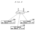
- an AP (Access Point) 1 as a base station of a wireless LAN as well as a VoIP terminal 100A (MAC address xx:xx:01), a VoIP terminal 100B (MAC address xx:xx:05), and a VoIP terminal 100C (MAC address xx:xx:04) as terminals of the wireless LAN mounted with IEEE 802.11 b, 802.11 e EDCA, and the present method constitute a wireless LAN network.
- VoIP terminals 100A and 100B are already communicating through VoIP and that the VoIP terminal 100C is connected to the AP 1 but is not communicating through VoIP at this point.
- the VoIP codec periods of the VoIP terminals 100A, 100B, and 100C are all 20 ms.
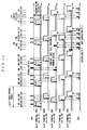
- FIG. 4 illustrates a sequence in which the VoId terminals 100A and 100B communicate with the AP 1 by VoIP packets as shown with times t1 to t8, while the VoIP terminal 100C participates later as shown with a time t21.
- the sequence diagram further depicts transmission priority periods (convex parts) of the VoIP terminals 100A, 100B, and 100C.
- the transmission priority periods are periods set up for the terminals to be able to transmit packets with priority over other terminals in accordance with the scheduling table.
- the VoIP terminals 100A and 100B perform transmission in the times t1 to t8 in accordance with already created and shared scheduling table.
- broadcast packets storing the scheduling tables describing an order of transmission by the terminals in the VoIP communication are periodically transmitted.
- the transmission is performed at times t1, t5, and t23 in the VoIP terminal 100A, at times t3, t7, and t27 in the VoIP terminal 100B, and at a time t25 in the VoIP terminal 100C.
- the VoIP terminal 100A transmits the scheduling table at a time t9. As shown with a time t10, not only the VoIP terminal 100B in VoIP communication, but also the VoIP terminal 100C that is not in VoIP communication but connected to the AP 1 receives the scheduling table packets transmitted by the VoIP terminal 100A. In this way, the terminal 100C that is not in VoIP communication can also recognize the VoIP communication schedule in the cell.
- the scheduling table transmitted at this point may have, for example, a MAC address as a terminal ID as shown in FIG. 5 .
- the VoIP terminal 100C creates a new table as shown in FIG. 6 in which the MAC address of the terminal is additionally written in the already held scheduling table as shown in FIG. 5 .
- the terminal 100C transmits the scheduling packets described with the new scheduling table by broadcasting at the time t21.
- the broadcast packets are relayed by the AP 1 and received by the VoIP terminals 100A and 100B at a time t22.
- An update time may also be described in the scheduling table.
- the update time denotes time information described when a terminal that updates the table actually rewrites the scheduling table.
- the VoIP terminals 100A and 100B update the scheduling tables held in the terminals when the update time of the received scheduling table is newer than the update time of the table held by the terminal and different from the order of transmission.
- the VoIP terminals 100A, 100B, and 100C share the new scheduling table.
- the VoIP terminals 100A, 100B, and 100C then set transmission periods of the terminals based on the new scheduling table as shown with the times t23, t25, and t27 and transmit VoIP packets based on the transmission periods. This realizes an update of the scheduling table when a new terminal starts communicating.
- the VoIP terminal 100C may transmit the scheduling table a plurality of times.
- the VoIP terminal 100C may also periodically broadcast the scheduling table. In this way, even if there is a terminal that has failed to receive the first broadcast packets of the scheduling table, the terminal can succeed in receiving the broadcast packets in a second or subsequent transmission.
- the above example is an example of the terminal periodically broadcasting the scheduling table, any of the following methods may be employed.
- the scheduling table may not be periodically broadcasted.
- the scheduling table may be broadcasted only when new communication is started. In this case, the sequence would be as shown in FIG. 7 .
- the VoIP terminal 100A As shown with times t30 and t31, it is assumed that only the VoIP terminal 100A is in VolP communication first.
- the VoIP terminal 100B then starts communicating at a time t32.
- the VoIP terminal 100C can receive the scheduling packets transmitted by the VoIP terminal 100B by broadcasting at the start of communication.
- the VoIP terminal 100C creates a new scheduling table upon the start of communication as shown with a time t38 and only has to transmit the new scheduling table through the AP 1 by broadcasting as shown with a time t39.
- This method is advantageous in that the overhead is small because the scheduling table does not have to be periodically transmitted.
- the scheduling table may not be shared if there is a terminal that has failed in the reception because the reception of the broadcast packets cannot be checked as the receiver does not return Ack (acknowledgment) packets.
- the method of periodically broadcasting the scheduling table achieves higher reliability for all terminals to receive the scheduling table by transmitting the scheduling table for a number of times.
- Each VoIP terminal described in the present invention comprises a hardware configuration shown in FIG. 1 and functional blocks shown in FIG. 2 .
- the configuration example of the wireless LAN network in the present embodiment is similar to the one in FIG. 3 .
- the VoIP terminals 100A, 100B, and 100C perform VoIP packet communication with the AP 1 in accordance with the scheduling table shown in FIG. 6 . Although only three terminals 100A, 100B, and 100C are described for the simplification of the description, any appropriate number of wireless terminals may exist. In the present embodiment, the VoIP codec periods of the VoIP terminals 100A, 100B, and 100C are all 20 ms.
- a scheduling method in the present technology in which the VoIP terminal 100C stops VoIP communication under these conditions will be described with reference to FIG. 8 .
- FIG. 8 illustrates a sequence in which the VoIP terminals 100A, 100B, and 100C communicate with the AP 1 by VoIP packets as shown with times t50 to t61, and the VoIP terminal 100C later stops the VoIP communication as shown with a time t62.
- the sequence diagram further depicts transmission priority periods (convex parts) of the VoIP terminals 100A, 100B, and 100C.
- the terminal 100C transmits a new scheduling table, in which the terminal information is removed, by broadcasting through the AP 1 as shown with times t62 and t63.
- a scheduling table described with information of only the VoIP terminals 100A and 100B as shown in FIG. 9 is transmitted.
- the VoIP terminal 100C may transmit the scheduling table immediately before the end of or immediately after the actual end of the VoIP communication.
- the scheduling table may be transmitted once or any appropriate number of times. This enables to inform the VoIP terminals 100A and 100B that the VoIP terminal 100C has ended communicating.
- the VoIP terminals 100A and 100B continue communicating based on the updated scheduling table as shown with times t64 to t71.
- the scheduling table at the end of communication is not transmitted, the following problems occur. If the VoIP terminal 100C arbitrarily ends communication, the transmission priority period of the VoIP terminal 100C is removed between the transmission priority periods of the VoIP terminal 100A and 100B. Furthermore, when a terminal that is not mounted with the present technology other than the terminals 100A, 100B, and 100C exists, the terminal may generate an interrupt by packet transmission. The sequence of transmitting in order according to the schedule may fall apart if an interrupt is generated. The second embodiment can prevent the problems from occurring.
- the VoIP terminal 100C may end the VoIP communication without transmitting anything. This is advantageous in that the overhead of transmitting the scheduling table is reduced.
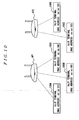
- each VoIP terminal described in the present embodiment comprises the hardware configuration shown in FIG. 1 and the functional blocks shown in FIG. 2 . It is also assumed that the configuration example of the wireless LAN network in the present embodiment has a configuration shown in FIG. 10 .
- the cell under the control of the AP 1 refers to a first cell, while the cell under the control of the AP 2 refers to a second cell.
- all terminals are VoIP terminals of wireless LAN mounted with IEEE 802.11 b, 802.11 e EDCA, and the present method.
- the VoIP terminal 100A (MAC address xx:xx:01), the VoIP terminal 100B (MAC address xx:xx:05), and the VoIP terminal 100C (MAC address xx:xx:04) exist in the first cell.
- a VoIP terminal 100D (MAC address xx:xx:03) and a VoIP terminal 100E (MAC address xx:xx:09) exist in the second cell.
- Each of the first cell and the second cell constitutes a wireless LAN network.
- the VoIP terminals 100A, 100B, and 100C perform VoIP packet communication with the AP 1 in the first cell in accordance with the scheduling table shown in FIG. 6 .
- the VoIP terminals 100D and 100E perform VoIP packet communication with the AP 2 in the second cell in accordance with a schedule shown in FIG. 11 .
- the VoIP codec periods of the terminals are all 20 ms in the present embodiment. Although two cells exist in the present embodiment, any appropriate number of the cells may exist.
- a scheduling method in the present technology in which the VoIP terminal 100C moves from the first cell to the second cell under these conditions with the VoIP communication being maintained will be described with reference to FIG. 11 .
- FIG. 11 illustrates a sequence in which the VoIP terminals 100A, 100B, and 100C communicate with the AP 1 by VoIP packets in accordance with the scheduling table shown in FIG. 6 , the VoIP terminals 100D and 100E communicate with the AP 2 by VoIP packets in accordance with the scheduling table shown in FIG. 11 , and as shown with a time t103, the VoIP terminal 100C later moves to the second cell with the VoIP communication maintained.
- the present sequence diagram further depicts transmission priority periods (convex parts) of the terminals 100A, 100B, 100C, 100D, and 100E.
- the VoIP terminal 100C first transmits a scheduling table, in which the terminal information of the VoIP terminal 100C is removed from the scheduling table of FIG. 6 , by broadcasting in order to inform other VoIP terminals 100A and 100B in the first cell that the VoIP terminal 100C will move out from the first cell.
- the scheduling table can be a table which is shown in FIG. 9 , for example.
- the scheduling table at the end of communication is not transmitted, the following problems occur. If the VoIP terminal 100C arbitrarily exits the first cell, the transmission priority period of the VoIP terminal 100C is removed between the transmission priority periods of the VoIP terminals 100A and 100B. Furthermore, when a terminal that is not mounted with the present technology other than the VoIP terminals 100A, 100B, and 100C exists, the terminal that is not mounted with the present technology may generate an interrupt by packet transmission. The sequence of transmitting in order according to the schedule may fall apart if an interrupt is generated. The third embodiment can prevent the problems from occurring.
- the VoIP terminal 100C Having moved to the second cell, the VoIP terminal 100C is not registered in the scheduling table of the second cell at first. Therefore, the VoIP terminal 100C performs a VoIP packet communication with the AP 2 by random access according to a normal wireless LAN access as shown with a time t103.
- a terminal in VoIP communication periodically transmits broadcast packets stored in a scheduling table described with an order of transmission.
- the VoIP terminal 100E performs the transmission as shown with times t85, t92, t101, t112, and t123.
- the VoIP terminal 100E performs the transmission, another terminal in the cell, i.e. the VoIP terminal 100D, may perform the transmission.
- the scheduling table can be a table which is shown in FIG. 12 .
- the VoIP terminal 100C After receiving the periodically broadcasted scheduling table of the second cell, the VoIP terminal 100C updates the scheduling table shown in FIG. 12 by additionally writing the terminal information of the VolP terminal 1 00C and then transmits the new scheduling table by broadcasting through the AP 2 as shown with a time t105.
- the new scheduling table can be a table which is shown in FIG. 13 .
- the new scheduling table among the terminals 100C, 100D, and 100E belonging to the second cell is updated.
- the terminals 100C, 100D, and 100E continue communicating based on the updated scheduling table.
- the transmission periods of the terminals in the scheduling table may have expiration time functions. More specifically, after a certain period has passed, the transmission period of the terminal may become invalid, and if the terminal still desires to set the transmission period, the terminal may transmit the scheduling table by broadcasting to inform other terminals.
- a transmission period setting time as shown in FIG. 14 is described as an element in a scheduling table example prior to the movement by the VoIP terminal 100C of the first cell in the present embodiment.
- the wireless communication device and the wireless communication method of the present invention are suitably available when performing priority control of communication with excellent quality in a network for communication in the CSMA/CA system.
Landscapes
- Engineering & Computer Science (AREA)
- Computer Networks & Wireless Communication (AREA)
- Signal Processing (AREA)
- Multimedia (AREA)
- Quality & Reliability (AREA)
- Mobile Radio Communication Systems (AREA)
- Small-Scale Networks (AREA)
Description
- The present invention relates to a wireless communication device and a wireless communication method that perform a communication priority control in a wireless LAN (Local Area Network) communication system, particularly in a CSMA/CA (Carrier Sense Multiple Access with Collision Avoidance) system.
- From
EP 1 484 873 A1 - In a CSMA/CA system, a terminal performs virtual carrier sensing for a certain random period before transmission and checks whether another terminal is communicating with a wireless base station. If another terminal is communicating with a wireless base station, the terminal waits for the completion of the communication and then performs actual packet transmission. All terminals have equal rights to transmission.
- The virtual carrier sensing denotes an act of generating a random number within a predetermined CW (Contention Window) after a channel has become idled for an IFS (Inter Frame Space) period, determining a random period based on the random number, and performing a back-off control in the random period.
- The back-off control denotes a control in which a calculated random value is set as an initial value, the value is reduced along with a lapse of time, and actual packet transmission is performed when the value becomes zero. The IFS is defined by the IEEE 802.11 wireless LAN standard and is a specific period in which an idle detection should be performed prior to the transmission.
- The CW is a maximum value of the random value that can be adopted in the back-off and is a parameter required to realize user multiplexing. The IEEE 802.11 defines a minimum value CWmin and a maximum value CWmax of the CW. A random value is calculated using the value of CWmin in the back-off of the first transmission, and the back-off is performed after doubling the CW in every retransmission. The CWmax denotes an upper limit of the CW.
- The back-off dependent on the randomness enables a plurality of terminals to share the same channel for communication. However, in the system, a plurality of terminals may simultaneously transmit packets. In that case, a packet collision occurs and the packets are not appropriately received, resulting in the degradation of the communication quality. Particularly, due to the above reasons, the transmission quality is significantly degraded in a real-time application such as the VoIP (Voice over Internet Protocol).
- An example of a conventional technology related to the priority control in such a communication system includes the EDCA (Enhanced Distributed Channel Access) defined in IEEE 802.11 e as shown in Part 11: Wireless LAN Medium Access Control (MAC) and Physical Layer (PHY) specifications: Amendment 7: Medium Access Control (MAC) Quality of Service (QoS) Enhancements. In the EDCA, any one of four types of priorities is applied to packets, respectively, and packet transmission rights are preferentially given to the packets with high priorities by shortening the transmission latency of the IFS, CWmin, CWmax, and so forth. This allows a relative priority control in a communication environment where various applications such as voice and data are mixed.
- However, the conventional EDCA method only provides a relative transmission priority order of the packets with different priorities. The method is a technique that does not contribute to the quality assurance or granting of priority among terminals that transmit packets with the same priority. Therefore, the possibility of an occurrence of packet collision caused by a plurality of terminals simultaneously transmitting the packets with the same priority cannot be inhibited. When the packet collision occurs, there is a delay even if the retransmission succeeds, and a packet loss occurs if the retransmission fails. Furthermore, when a plurality of terminals perform the back-off to obtain the packet transmission rights, there is a transmission latency or a delay for obtaining the transmission rights for a terminal deprived of the retransmission rights by other terminals. The incidence of the disadvantages is higher as the number of the terminals increases. Particularly, the delay or the packet loss generated by the disadvantages leads to a significant degradation of quality in a real-time application represented by the VoIP.
- An example of a method for solving such disadvantages includes a technology for controlling the packet collision by setting packet transmission right obtaining priority periods with different timings among wireless terminals for each VoIP packet generation cycle as shown in
JP 2007-214795 A JP 2007-235445 A JP 2007-214795 A - However, the terminals have to always or periodically receive downlink packets for other terminals from an AP (Access Point) in the technology of
JP 2007-235445 A - The present invention has been made in view of the foregoing problems, and an object of the present invention is to provide a wireless communication device and a wireless communication method capable of realizing distributed autonomous transmission scheduling only by a terminal without the need to observe packets in relation to communication of other wireless terminals in a cell, such as VoIP, in which a plurality of wireless terminals that periodically transmit packets exist, thereby allowing intermittent reception during the packet observation and enabling to control power consumption of the wireless terminal as well as to reduce the load to thereby improve the communication quality.
- To attain the object, a first aspect of the present invention provides a
- wireless communication device (100) adapted to transmit and receive packets based on a packet transmission system for allocating a radio bandwidth by a virtual carrier sensing, the wireless communication device (100) comprising:
- a first transmitting means (204) for periodically or occasionally transmitting a scheduling table created by at least one of a plurality of wireless communication devices (100), to a wireless base station, and retained and updated by each of the plurality of wireless communication devices (100), the scheduling table including at least an order of transmission by the terminals and an update time denoting time information described when said at least one of the plurality of wireless communication devices (100) updates the scheduling table;
- a recognizing and retaining means (202) for recognizing and retaining the scheduling table received when the wireless communication device (100) is connected to the wireless base station and is not communicating with another wireless communication device (100);
- a second transmitting means for additionally writing information of the wireless communication device (100) to the scheduling table which is retained by the recognizing and retaining means (202) at the beginning of communication and for transmitting the additionally-written scheduling table at least once;
- an updating means (205) for updating the scheduling table retained by the wireless communication device (100) with another scheduling table, when another update time of said another scheduling table received from the wireless base station is later than the update time of the scheduling table retained by the wireless communication device (100) and another order of transmission received from the wireless base station is different from the order of transmission in the scheduling table retained by the wireless communication device (100); and
- a third transmitting means (206) for communicating after setting an exclusive or preferential bandwidth available period in accordance with the scheduling table updated by the updating means (205).
- The configuration can realize distributed autonomous transmission scheduling only by the terminal without the need to observe packets in relation to communication of other wireless terminals. Therefore, the configuration allows intermittent reception during the packet observation and enables to control power consumption of the wireless terminal as well as to reduce the load to thereby improve the communication quality.
- In the above configuration, the updating means may delete the information of the wireless communication device from the scheduling table immediately before transition to a state of being connected only to the wireless base station or immediately after an end of communication, after at least one of the plurality of wireless communication devices that has been in communication ends the communication in accordance with the scheduling table; and the third transmitting means transmits the scheduling table from which the information is deleted, at least once.
- Conventionally, if a wireless terminal arbitrarily ends communication, the transmission priority period of the other wireless terminal is removed between the transmission priority periods of a plurality of wireless terminals in communication. Furthermore, if another wireless terminal exists, an interrupt may be generated by packet transmission from the terminal. The generation of the interrupt may cause a problem that a sequence of transmitting in order according to the schedule falls apart. The above configuration deletes the terminal information from the scheduling table, thereby preventing the problem from occurring.
- In the above configuration, the updating means may delete the information of the wireless communication device from the scheduling table when at least one of the plurality of wireless communication devices in communication moves, while a communication state being maintained, from a cell which is a current communication area of the wireless base station to another cell having another wireless base station in accordance with the scheduling table; and the third transmitting means transmits the scheduling table from which the information is deleted, to the wireless base station at least once.
- Conventionally, if a wireless terminal arbitrarily moves the cell, the transmission priority period of the other wireless terminal is removed between the transmission priority periods of a plurality of wireless terminals in communication. Furthermore, if another wireless terminal exists, an interrupt may be generated by packet transmission from the terminal. The generation of the interrupt may cause a problem that a sequence of transmitting in order according to the schedule falls apart. The above configuration deletes the terminal information from the scheduling table, thereby preventing the problem from occurring.
- In the above configuration, the first transmitting means communicates by random accessing using virtual carrier sensing for a predetermined time, after the wireless communication device moves to another cell; and the second transmitting means additionally writes the information of the wireless communication device in the scheduling table received from another wireless communication device while random accessing after the wireless communication device moves to another cell and transmits the additionally-written scheduling table to the wireless base station at least once.
- According to the configuration, the plurality of wireless base stations in the cell after the movement receive the additionally written scheduling table, and the other wireless terminals belonging to the cell update the scheduling table to the new scheduling table. Therefore, the other wireless terminals can continue to communicate based on the updated scheduling table.
- In the above configuration, a transmission valid period that becomes invalid after a lapse of a predetermined period may be written in the scheduling table.
- The configuration can prevent an unnecessary transmission period for a wireless terminal that has exited the cell from being continuously set after the wireless terminal has exited the cell.
- A second aspect of the present invention provides a wireless communication method for transmitting and receiving packets based on a packet transmission system for allocating a radio bandwidth by virtual carrier sensing, the wireless communication method comprising:
- a first step for periodically or occasionally transmitting a scheduling table, created by at least one of a plurality of wireless communication devices (100), to a wireless base station, and retained and updated by each of the plurality of wireless communication devices (100), the scheduling table including at least an order of transmission by the terminals and an update time denoting time information described when said at least one of the plurality of wireless communication devices (100) updates the scheduling table;
- a second step for recognizing and retaining the scheduling table received when the wireless communication device (100) is connected to the wireless base station and is not communicating with another wireless communication device (100);
- a third step for additionally writing information of the wireless communication device (100) to the scheduling table which is retained by the recognizing and retaining means (202) at the beginning of communication and for transmitting the additionally-written scheduling table at least once;
- a fourth step for updating the scheduling table retained by the wireless communication device (100) with another scheduling table, when another update time of said another scheduling table received from the wireless base station (100) is later than the update time of the scheduling table retained by the wireless communication device (100) and another order of transmission received from the wireless base station is different from the order of transmission in the scheduling table retained by the wireless communication device (100); and
- a fifth step for communicating after setting an exclusive or preferential bandwidth available period in accordance with the scheduling table updated at the fourth step.
- The method realizes distributed autonomous transmission scheduling only by a terminal without the need to observe packets in relation to communication of other wireless terminals. Therefore, the method allows intermittent reception during the packet observation and enables to control power consumption of the wireless terminal as well as to reduce the load to thereby improve the communication quality.
- As described, the present invention is capable of realizing distributed autonomous transmission scheduling only by a terminal without the need to observe packets in relation to communication of other wireless terminals in a cell, such as VoIP, in which a plurality of wireless terminals that periodically transmit packets exist, thereby allowing intermittent reception during the packet observation and enabling to control power consumption of the wireless terminal as well as to reduce the load to thereby improve the communication quality.
- Further objects, advantages and embodiments may be taken from the following description.
-
FIG. 1 is a block diagram of a hardware configuration of a VoIP terminal according to a first embodiment of the present invention; -
FIG. 2 is a functional block diagram of the VoIP terminal according to the first embodiment; -
FIG. 3 is a block diagram of a configuration of a wireless LAN network using the VoIP terminals according to the first embodiment; -
FIG. 4 is a sequence diagram for describing a scheduling method at the start of VoIP communication of the VoIP terminals according to the first embodiment; -
FIG. 5 is a configuration diagram of a scheduling table of the VoIP terminal; -
FIG. 6 is a configuration diagram of a scheduling table of the VoIP terminal; -
FIG. 7 is a sequence diagram at the start of new communication of the VoIP terminals according to the first embodiment; -
FIG. 8 is a sequence diagram for describing a scheduling method when VoIP communication of a VolP terminal is stopped according to a second embodiment of the present invention; -
FIG. 9 is a configuration diagram of a scheduling table of the VoIP terminal; -
FIG. 10 is a block diagram of a configuration of a wireless LAN network using the VoIP terminals according to the second embodiment; -
FIG. 11 is a sequence diagram for describing a scheduling method during VoIP communication of the VoIP terminals according to a third embodiment of the present invention; -
FIG. 12 is a configuration diagram of a scheduling table of the VoIP terminal; -
FIG. 13 is a configuration diagram of a scheduling table of the VoIP terminal; and -
FIG. 14 is a configuration diagram of a scheduling table example when the VoIP terminal moves to another cell. - The embodiments of the present invention will now be described with reference to the drawings. Corresponding elements are designated with like reference numerals throughout the drawings in the present specification, and the description of the overlapping parts will be appropriately omitted.
-
FIG. 1 is a block diagram of a hardware configuration of a VoIP terminal according to a first embodiment of the present invention. The present embodiment describes a scenario in which a VoIP terminal (wireless communication device) 100 starts VoIP communication. - As shown in
FIG. 1 , theVoIP terminal 100 comprises: aCPU 101 as an information processing device; aROM 102 and aRAM 103 as a compact hard disk or a semiconductor memory device; anoperating unit 104 such as a key button for a user to operate and input information; awireless communication unit 105 capable of wireless communication by a CSMA/CA system; and adisplay 106 formed of liquid crystal, organic EL, or the like. - As shown in a functional block diagram of
FIG. 2 , theVoIP terminal 100 includes a processing function comprising apacket receiving unit 201, a scheduling table recognizing and retaining unit (recognizing and retaining means) 202, a wireless access controllingparameter setting unit 203, a packet transmission controlling unit 204 (first transmitting means), a scheduling table creating unit (updating means) 205, and a scheduling packet transmission controlling unit (third transmitting means) 206. The packettransmission controlling unit 204 constitutes second transmitting means in collaboration with the wireless access controllingparameter setting unit 203. - The
packet receiving unit 201 is mounted on thewireless communication unit 105 and includes a function for receiving packets from an AP (Access Point) which is not shown. - The scheduling table recognizing and retaining
unit 202, which is mounted on theCPU 101, theROM 102, or theRAM 103, receives the scheduling packets from thepacket receiving unit 201, then recognizes and retains a scheduling table described in the packets. - The wireless access controlling
parameter setting unit 203, mounted on thewireless communication unit 105, receives scheduling table information from the scheduling table recognizing and retainingunit 202 and uses the table information to set parameters in relation to the actual packet transmission. - The packet
transmission controlling unit 204 is mounted on thewireless communication unit 105 and transmits transmission packets generated inside thepresent VoIP terminal 100 based on the parameters set by the wireless access controllingparameter setting unit 203. - The scheduling
table creating unit 205, which is mounted on theCPU 101, theROM 102, or theRAM 103, creates and updates a new scheduling table based on the scheduling table at the time obtained from the scheduling table recognizing and retainingunit 202 when the terminal desires to start new communication, stop the communication, or hand over the communication. - The scheduling packet
transmission controlling unit 206, mounted on thewireless communication unit 105, receives the new scheduling table information created by the schedulingtable creating unit 205 and transmits the new scheduling table information to an AP by packets (new scheduling table packets). - As shown in
FIG. 3 , it is assumed that an AP (Access Point) 1 as a base station of a wireless LAN as well as aVoIP terminal 100A (MAC address xx:xx:01), aVoIP terminal 100B (MAC address xx:xx:05), and aVoIP terminal 100C (MAC address xx:xx:04) as terminals of the wireless LAN mounted with IEEE 802.11 b, 802.11 e EDCA, and the present method constitute a wireless LAN network. - It is also assumed that the
VoIP terminals VoIP terminal 100C is connected to theAP 1 but is not communicating through VoIP at this point. Although only three wireless terminals are described for the simplification of the description, any appropriate number of wireless terminals may exist. In the present embodiment, the VoIP codec periods of theVoIP terminals - Under these conditions, a scheduling method of the present technology when the
VoIP terminal 100C starts the VoIP communication will be described with reference to a sequence diagram shown inFIG. 4 . -
FIG. 4 illustrates a sequence in which theVoId terminals AP 1 by VoIP packets as shown with times t1 to t8, while theVoIP terminal 100C participates later as shown with a time t21. - The sequence diagram further depicts transmission priority periods (convex parts) of the
VoIP terminals VoIP terminals - In the present technology, broadcast packets storing the scheduling tables describing an order of transmission by the terminals in the VoIP communication are periodically transmitted. The transmission is performed at times t1, t5, and t23 in the
VoIP terminal 100A, at times t3, t7, and t27 in theVoIP terminal 100B, and at a time t25 in theVoIP terminal 100C. - In
FIG. 4 , theVoIP terminal 100A transmits the scheduling table at a time t9. As shown with a time t10, not only theVoIP terminal 100B in VoIP communication, but also theVoIP terminal 100C that is not in VoIP communication but connected to theAP 1 receives the scheduling table packets transmitted by theVoIP terminal 100A. In this way, the terminal 100C that is not in VoIP communication can also recognize the VoIP communication schedule in the cell. The scheduling table transmitted at this point may have, for example, a MAC address as a terminal ID as shown inFIG. 5 . - Assuming that the terminal 100C needs to perform VoIP communication as shown with the time t21 because of reasons such as the user having the
VoIP terminal 100C starts VoIP communication or the terminal 100C receives a call, in this case, theVoIP terminal 100C creates a new table as shown inFIG. 6 in which the MAC address of the terminal is additionally written in the already held scheduling table as shown inFIG. 5 . - More specifically, the terminal 100C transmits the scheduling packets described with the new scheduling table by broadcasting at the time t21. The broadcast packets are relayed by the
AP 1 and received by theVoIP terminals - The update time denotes time information described when a terminal that updates the table actually rewrites the scheduling table. The
VoIP terminals - As a result, the
VoIP terminals VoIP terminals - Although the
VoIP terminal 100C transmits the scheduling table only once in the present embodiment, theVoIP terminal 100C may transmit the scheduling table a plurality of times. TheVoIP terminal 100C may also periodically broadcast the scheduling table. In this way, even if there is a terminal that has failed to receive the first broadcast packets of the scheduling table, the terminal can succeed in receiving the broadcast packets in a second or subsequent transmission. Although the above example is an example of the terminal periodically broadcasting the scheduling table, any of the following methods may be employed. - More specifically, a terminal that is connected to the AP but not in communication may periodically broadcast the scheduling table. In the present embodiment, the scheduling table may be broadcasted when the
VoIP terminal 100C is in the idle state. - Alternatively, the scheduling table may not be periodically broadcasted. In other words, the scheduling table may be broadcasted only when new communication is started. In this case, the sequence would be as shown in
FIG. 7 . - As shown with times t30 and t31, it is assumed that only the
VoIP terminal 100A is in VolP communication first. TheVoIP terminal 100B then starts communicating at a time t32. At that point, as shown with a time t33, theVoIP terminal 100C can receive the scheduling packets transmitted by theVoIP terminal 100B by broadcasting at the start of communication. - Subsequently, the
VoIP terminal 100C creates a new scheduling table upon the start of communication as shown with a time t38 and only has to transmit the new scheduling table through theAP 1 by broadcasting as shown with a time t39. - This method is advantageous in that the overhead is small because the scheduling table does not have to be periodically transmitted. However, the scheduling table may not be shared if there is a terminal that has failed in the reception because the reception of the broadcast packets cannot be checked as the receiver does not return Ack (acknowledgment) packets.
- On the other hand, although the overhead becomes large as the scheduling table is transmitted, the method of periodically broadcasting the scheduling table achieves higher reliability for all terminals to receive the scheduling table by transmitting the scheduling table for a number of times.
- In the present embodiment, an application example of the present technology in which the
VoIP terminal 100 in communication stops communication and returns to the idle state will be described. - Each VoIP terminal described in the present invention comprises a hardware configuration shown in
FIG. 1 and functional blocks shown inFIG. 2 . The configuration example of the wireless LAN network in the present embodiment is similar to the one inFIG. 3 . - Furthermore, the
VoIP terminals AP 1 in accordance with the scheduling table shown inFIG. 6 . Although only threeterminals VoIP terminals - A scheduling method in the present technology in which the
VoIP terminal 100C stops VoIP communication under these conditions will be described with reference toFIG. 8 . -
FIG. 8 illustrates a sequence in which theVoIP terminals AP 1 by VoIP packets as shown with times t50 to t61, and theVoIP terminal 100C later stops the VoIP communication as shown with a time t62. The sequence diagram further depicts transmission priority periods (convex parts) of theVoIP terminals - When the
VoIP terminal 100C stops the VoIP communication, the terminal 100C transmits a new scheduling table, in which the terminal information is removed, by broadcasting through theAP 1 as shown with times t62 and t63. Thus, a scheduling table described with information of only theVoIP terminals FIG. 9 is transmitted. - The
VoIP terminal 100C may transmit the scheduling table immediately before the end of or immediately after the actual end of the VoIP communication. The scheduling table may be transmitted once or any appropriate number of times. This enables to inform theVoIP terminals VoIP terminal 100C has ended communicating. TheVoIP terminals - If the scheduling table at the end of communication is not transmitted, the following problems occur. If the
VoIP terminal 100C arbitrarily ends communication, the transmission priority period of theVoIP terminal 100C is removed between the transmission priority periods of theVoIP terminal terminals - Alternatively, the
VoIP terminal 100C may end the VoIP communication without transmitting anything. This is advantageous in that the overhead of transmitting the scheduling table is reduced. - An application example of the present technology, in which a terminal in communication moves between cells in the communication state, will be described in the present embodiment.
- It is assumed that each VoIP terminal described in the present embodiment comprises the hardware configuration shown in
FIG. 1 and the functional blocks shown inFIG. 2 . It is also assumed that the configuration example of the wireless LAN network in the present embodiment has a configuration shown inFIG. 10 . - Two cells not shown exist in
FIG. 10 , and theAP 1 and anAP 2 as base stations of the wireless LAN exist in respective cells. The cell under the control of theAP 1 refers to a first cell, while the cell under the control of theAP 2 refers to a second cell. In the present embodiment, all terminals are VoIP terminals of wireless LAN mounted with IEEE 802.11 b, 802.11 e EDCA, and the present method. - The
VoIP terminal 100A (MAC address xx:xx:01), theVoIP terminal 100B (MAC address xx:xx:05), and theVoIP terminal 100C (MAC address xx:xx:04) exist in the first cell. AVoIP terminal 100D (MAC address xx:xx:03) and aVoIP terminal 100E (MAC address xx:xx:09) exist in the second cell. Each of the first cell and the second cell constitutes a wireless LAN network. - The
VoIP terminals AP 1 in the first cell in accordance with the scheduling table shown inFIG. 6 . TheVoIP terminals AP 2 in the second cell in accordance with a schedule shown inFIG. 11 . Although only fiveterminals - A scheduling method in the present technology in which the
VoIP terminal 100C moves from the first cell to the second cell under these conditions with the VoIP communication being maintained will be described with reference toFIG. 11 . -
FIG. 11 illustrates a sequence in which theVoIP terminals AP 1 by VoIP packets in accordance with the scheduling table shown inFIG. 6 , theVoIP terminals AP 2 by VoIP packets in accordance with the scheduling table shown inFIG. 11 , and as shown with a time t103, theVoIP terminal 100C later moves to the second cell with the VoIP communication maintained. The present sequence diagram further depicts transmission priority periods (convex parts) of theterminals - Once the
VoIP terminal 100C mounted with the present technology moves from the first cell to the second cell with the VoIP communication maintained, theVoIP terminal 100C first transmits a scheduling table, in which the terminal information of theVoIP terminal 100C is removed from the scheduling table ofFIG. 6 , by broadcasting in order to informother VoIP terminals VoIP terminal 100C will move out from the first cell. The scheduling table can be a table which is shown inFIG. 9 , for example. - This enables to inform the
VoIP terminals VoIP terminal 100C has exited the first cell, and theVoIP terminals - If the scheduling table at the end of communication is not transmitted, the following problems occur. If the
VoIP terminal 100C arbitrarily exits the first cell, the transmission priority period of theVoIP terminal 100C is removed between the transmission priority periods of theVoIP terminals VoIP terminals - Alternatively, the
VoIP terminal 100C may exit the first cell without transmitting anything. This is advantageous in that the overhead of transmitting the scheduling table is reduced. - Having moved to the second cell, the
VoIP terminal 100C is not registered in the scheduling table of the second cell at first. Therefore, theVoIP terminal 100C performs a VoIP packet communication with theAP 2 by random access according to a normal wireless LAN access as shown with a time t103. - In the present technology, a terminal in VoIP communication periodically transmits broadcast packets stored in a scheduling table described with an order of transmission. In the second cell of the present embodiment, the
VoIP terminal 100E performs the transmission as shown with times t85, t92, t101, t112, and t123. Although theVoIP terminal 100E performs the transmission, another terminal in the cell, i.e. theVoIP terminal 100D, may perform the transmission. The scheduling table can be a table which is shown inFIG. 12 . - After receiving the periodically broadcasted scheduling table of the second cell, the
VoIP terminal 100C updates the scheduling table shown inFIG. 12 by additionally writing the terminal information of theVolP terminal 1 00C and then transmits the new scheduling table by broadcasting through theAP 2 as shown with a time t105. The new scheduling table can be a table which is shown inFIG. 13 . As the terminals in the second cell receive the new scheduling table, the new scheduling table among theterminals terminals - The transmission periods of the terminals in the scheduling table may have expiration time functions. More specifically, after a certain period has passed, the transmission period of the terminal may become invalid, and if the terminal still desires to set the transmission period, the terminal may transmit the scheduling table by broadcasting to inform other terminals.
- This enables to prevent an unnecessary transmission period for an exited wireless terminal from being continuously set even after the wireless terminal has exited the cell. A transmission period setting time as shown in
FIG. 14 is described as an element in a scheduling table example prior to the movement by theVoIP terminal 100C of the first cell in the present embodiment. - The wireless communication device and the wireless communication method of the present invention are suitably available when performing priority control of communication with excellent quality in a network for communication in the CSMA/CA system.
Claims (6)
- A wireless communication device (100) adapted to transmit and receive packets based on a packet transmission system for allocating a radio bandwidth by a virtual carrier sensing, the wireless communication device (100) comprising:a first transmitting means (204) for periodically or occasionally transmitting a scheduling table created by at least one of a plurality of wireless communication devices (100), to a wireless base station, and retained and updated by each of the plurality of wireless communication devices (100), the scheduling table including at least an order of transmission by the terminals and an update time denoting time information described when said at least one of the plurality of wireless communication devices (100) updates the scheduling table;a recognizing and retaining means (202) for recognizing and retaining the scheduling table received when the wireless communication device (100) is connected to the wireless base station and is not communicating with another wireless communication device (100);a second transmitting means for additionally writing information of the wireless communication device (100) to the scheduling table which is retained by the recognizing and retaining means (202) at the beginning of communication and for transmitting the additionally-written scheduling table at least once;an updating means (205) for updating the scheduling table retained by the wireless communication device (100) with another scheduling table, when another update time of said another scheduling table received from the wireless base station is later than the update time of the scheduling table retained by the wireless communication device (100) and another order of transmission received from the wireless base station is different from the order of transmission in the scheduling table retained by the wireless communication device (100); anda third transmitting means (206) for communicating after setting an exclusive or preferential bandwidth available period in accordance with the scheduling table updated by the updating means (205).
- The wireless communication device (100) according to claim 1, wherein:the updating means (205) deletes the information of the wireless communication device (100) from the scheduling table immediately before transition to a state of being connected only to the wireless base station or immediately after an end of communication, after at least one of the plurality of wireless communication devices (100) that has been in communication ends the communication in accordance with the scheduling table; andthe third transmitting means (206) transmits the scheduling table from which the information is deleted, at least once.
- The wireless communication device (100) according to claim 1, wherein:the updating means (205) deletes the information of the wireless communication device (100) from the scheduling table when at least one of the plurality of wireless communication devices (100) in communication moves, while a communication state being maintained, from a cell which is a current communication area of the wireless base station to another cell having another wireless base station in accordance with the scheduling table; andthe third transmitting means (206) transmits the scheduling table from which the information is deleted, to the wireless base station at least once.
- The wireless communication device (100) according to claim 3, wherein:the first transmitting means (204) communicates by random accessing using virtual carrier sensing for a predetermined time, after the wireless communication device (100) moves to another cell; andthe second transmitting means additionally writes the information of the wireless communication device (100) in the scheduling table received from another wireless communication device (100) while random accessing after the wireless communication device (100) moves to another cell and transmits the additionally-written scheduling table to the wireless base station at least once.
- The wireless communication device (100) according to any one of claims 1 to 4, wherein the scheduling table comprises a transmission valid period that becomes invalid after a lapse of a predetermined period.
- A wireless communication method for transmitting and receiving packets based on a packet transmission system for allocating a radio bandwidth by virtual carrier sensing, the wireless communication method comprising:a first step for periodically or occasionally transmitting a scheduling table, created by at least one of a plurality of wireless communication devices (100), to a wireless base station, and retained and updated by each of the plurality of wireless communication devices (100), the scheduling table including at least an order of transmission by the terminals and an update time denoting time information described when said at least one of the plurality of wireless communication devices (100) updates the scheduling table;a second step for recognizing and retaining the scheduling table received when the wireless communication device (100) is connected to the wireless base station and is not communicating with another wireless communication device (100);a third step for additionally writing information of the wireless communication device (100) to the scheduling table which is retained by the recognizing and retaining means (202) at the beginning of communication and for transmitting the additionally-written scheduling table at least once;a fourth step for updating the scheduling table retained by the wireless communication device (100) with another scheduling table, when another update time of said another scheduling table received from the wireless base station (100) is later than the update time of the scheduling table retained by the wireless communication device (100) and another order of transmission received from the wireless base station is different from the order of transmission in the scheduling table retained by the wireless communication device (100); anda fifth step for communicating after setting an exclusive or preferential bandwidth available period in accordance with the scheduling table updated at the fourth step.
Applications Claiming Priority (1)
| Application Number | Priority Date | Filing Date | Title |
|---|---|---|---|
| JP2007206711A JP5201498B2 (en) | 2007-08-08 | 2007-08-08 | Wireless communication apparatus and wireless communication method |
Publications (3)
| Publication Number | Publication Date |
|---|---|
| EP2023552A2 EP2023552A2 (en) | 2009-02-11 |
| EP2023552A3 EP2023552A3 (en) | 2011-11-30 |
| EP2023552B1 true EP2023552B1 (en) | 2012-12-05 |
Family
ID=39988498
Family Applications (1)
| Application Number | Title | Priority Date | Filing Date |
|---|---|---|---|
| EP20080013964 Ceased EP2023552B1 (en) | 2007-08-08 | 2008-08-05 | Wireless communication device and wireless communication method |
Country Status (4)
| Country | Link |
|---|---|
| US (1) | US8144677B2 (en) |
| EP (1) | EP2023552B1 (en) |
| JP (1) | JP5201498B2 (en) |
| CN (1) | CN101364943B (en) |
Families Citing this family (5)
| Publication number | Priority date | Publication date | Assignee | Title |
|---|---|---|---|---|
| CN104838613B (en) * | 2012-12-03 | 2018-11-09 | 索尼公司 | Transmission of control information to terminals of reduced bandwidth |
| CN106656430B (en) * | 2015-10-28 | 2020-08-25 | 中兴通讯股份有限公司 | Listen first, then talk parameter processing method, competition window adjustment method and device |
| CN106533833B (en) * | 2016-11-24 | 2019-09-10 | 重庆邮电大学 | A method of reducing Carrier Sense Multiple Access resource contention |
| CN107124372A (en) * | 2017-04-28 | 2017-09-01 | 杭州万高通信技术有限公司 | It is a kind of that interval frame transmission method and its device can be used based on zero-crossing |
| JP7835467B2 (en) * | 2022-04-29 | 2026-03-25 | ウィルス インスティテュート オブ スタンダーズ アンド テクノロジー インコーポレイティド | Method and apparatus for transmitting signals in a wireless communication system |
Family Cites Families (15)
| Publication number | Priority date | Publication date | Assignee | Title |
|---|---|---|---|---|
| JP2001053745A (en) | 1999-08-11 | 2001-02-23 | Nippon Telegr & Teleph Corp <Ntt> | Wireless packet communication system |
| US6788702B1 (en) * | 1999-10-15 | 2004-09-07 | Nokia Wireless Routers, Inc. | Protocol for neighborhood-established transmission scheduling |
| US20040013135A1 (en) * | 2002-07-17 | 2004-01-22 | Yoram Haddad | System and method for scheduling traffic in wireless networks |
| US7580394B2 (en) * | 2002-11-27 | 2009-08-25 | Nokia Corporation | System and method for collision-free transmission scheduling in a network |
| JP4042901B2 (en) | 2002-11-28 | 2008-02-06 | Kddi株式会社 | Wireless terminal and wireless access control method thereof |
| JP2004186935A (en) * | 2002-12-03 | 2004-07-02 | Mitsubishi Electric Corp | Time slot allocation method and radio station |
| JP4582098B2 (en) | 2003-02-03 | 2010-11-17 | ソニー株式会社 | Wireless communication system, communication apparatus, communication method, and program |
| EP1592174B1 (en) | 2003-02-03 | 2014-12-24 | Sony Corporation | Radio communication system, radio communication device, radio communication method, and computer program |
| US20040219919A1 (en) * | 2003-04-30 | 2004-11-04 | Nicholas Whinnett | Management of uplink scheduling modes in a wireless communication system |
| KR100584326B1 (en) * | 2003-06-03 | 2006-05-26 | 삼성전자주식회사 | Short-range communication system and method in a wireless communication system |
| US7412265B2 (en) * | 2003-06-12 | 2008-08-12 | Industrial Technology Research Institute | Method and system for power-saving in a wireless local area network |
| JP4880316B2 (en) | 2006-02-08 | 2012-02-22 | 株式会社エヌ・ティ・ティ・ドコモ | Wireless communication apparatus and wireless communication method |
| JP4799213B2 (en) | 2006-02-28 | 2011-10-26 | 株式会社エヌ・ティ・ティ・ドコモ | Wireless communication terminal and wireless communication method |
| KR101389680B1 (en) * | 2007-02-06 | 2014-05-27 | 엘지전자 주식회사 | Wireless Communication system, Station and Access point for Wireless LAN system and Scheduling method thereof |
| US8325627B2 (en) * | 2007-04-13 | 2012-12-04 | Hart Communication Foundation | Adaptive scheduling in a wireless network |
-
2007
- 2007-08-08 JP JP2007206711A patent/JP5201498B2/en not_active Expired - Fee Related
-
2008
- 2008-08-05 EP EP20080013964 patent/EP2023552B1/en not_active Ceased
- 2008-08-07 CN CN2008101449188A patent/CN101364943B/en not_active Expired - Fee Related
- 2008-08-08 US US12/188,786 patent/US8144677B2/en not_active Expired - Fee Related
Also Published As
| Publication number | Publication date |
|---|---|
| JP2009044411A (en) | 2009-02-26 |
| US20090040991A1 (en) | 2009-02-12 |
| EP2023552A2 (en) | 2009-02-11 |
| EP2023552A3 (en) | 2011-11-30 |
| US8144677B2 (en) | 2012-03-27 |
| JP5201498B2 (en) | 2013-06-05 |
| CN101364943A (en) | 2009-02-11 |
| CN101364943B (en) | 2012-04-04 |
Similar Documents
| Publication | Publication Date | Title |
|---|---|---|
| JP5295882B2 (en) | Wireless communication device | |
| US10172146B2 (en) | Wi-Fi and bluetooth coexistence | |
| CN102217395B (en) | For the apparatus and method of channel reservation in wireless communication system | |
| EP4369797A1 (en) | Drx configuration method and apparatus, terminal device, and network device | |
| US11770752B2 (en) | Managing control plane latency for integrated access and backhaul | |
| US20090300457A1 (en) | Method and Apparatus for Improving HARQ Uplink Transmission | |
| CN107079470B (en) | Media access control for licensed assisted access | |
| US8081967B2 (en) | Method to manage medium access for a mixed wireless network | |
| US8416799B2 (en) | Systems, methods and apparatuses for wireless communication | |
| CN116250314A (en) | User equipment and its method for sidechain communication in unlicensed spectrum | |
| US20200068601A1 (en) | Resource scheduling method and device | |
| US8848676B1 (en) | Apparatus and method for coexistent wireless and bluetooth communication employing interruption of arbitration requests to allocate use of a shared antenna | |
| EP2023552B1 (en) | Wireless communication device and wireless communication method | |
| JP5932162B2 (en) | Temporary media handover | |
| CN113647171B (en) | Method and apparatus for wireless communication | |
| CN112423391A (en) | Resource indication method and device | |
| KR100801876B1 (en) | Voice data transmission method and system using wireless LAN and Bluetooth | |
| US20240057049A1 (en) | Resource indication method, apparatus, and system | |
| KR100741383B1 (en) | Voice data transmission method and system using wireless LAN and Bluetooth | |
| US20050013325A1 (en) | Method for transmitting multimedia data in wireless network | |
| US10271352B2 (en) | Wireless communication system and associated wireless communication method and wireless device having efficient polling mechanism in overlapping network environments | |
| Li et al. | Optimal Packetization Towards Low Latency in Random Access Networks (extended version) | |
| CN113747538A (en) | Priority determination method and device | |
| US20240214127A1 (en) | Method for data transmission, terminal device, and computer storage medium | |
| US20250159553A1 (en) | Transmission latency mitigation for voice over new radio (vonr) |
Legal Events
| Date | Code | Title | Description |
|---|---|---|---|
| PUAI | Public reference made under article 153(3) epc to a published international application that has entered the european phase |
Free format text: ORIGINAL CODE: 0009012 |
|
| 17P | Request for examination filed |
Effective date: 20080805 |
|
| AK | Designated contracting states |
Kind code of ref document: A2 Designated state(s): AT BE BG CH CY CZ DE DK EE ES FI FR GB GR HR HU IE IS IT LI LT LU LV MC MT NL NO PL PT RO SE SI SK TR |
|
| AX | Request for extension of the european patent |
Extension state: AL BA MK RS |
|
| PUAL | Search report despatched |
Free format text: ORIGINAL CODE: 0009013 |
|
| AK | Designated contracting states |
Kind code of ref document: A3 Designated state(s): AT BE BG CH CY CZ DE DK EE ES FI FR GB GR HR HU IE IS IT LI LT LU LV MC MT NL NO PL PT RO SE SI SK TR |
|
| AX | Request for extension of the european patent |
Extension state: AL BA MK RS |
|
| RIC1 | Information provided on ipc code assigned before grant |
Ipc: H04W 72/12 20090101AFI20111021BHEP |
|
| REG | Reference to a national code |
Ref country code: DE Ref legal event code: R079 Ref document number: 602008020543 Country of ref document: DE Free format text: PREVIOUS MAIN CLASS: H04L0012560000 Ipc: H04W0072120000 |
|
| GRAP | Despatch of communication of intention to grant a patent |
Free format text: ORIGINAL CODE: EPIDOSNIGR1 |
|
| RIC1 | Information provided on ipc code assigned before grant |
Ipc: H04W 72/12 20090101AFI20120613BHEP |
|
| AKX | Designation fees paid |
Designated state(s): DE GB |
|
| GRAS | Grant fee paid |
Free format text: ORIGINAL CODE: EPIDOSNIGR3 |
|
| GRAA | (expected) grant |
Free format text: ORIGINAL CODE: 0009210 |
|
| AK | Designated contracting states |
Kind code of ref document: B1 Designated state(s): DE GB |
|
| REG | Reference to a national code |
Ref country code: GB Ref legal event code: FG4D |
|
| REG | Reference to a national code |
Ref country code: DE Ref legal event code: R096 Ref document number: 602008020543 Country of ref document: DE Effective date: 20130131 |
|
| PLBE | No opposition filed within time limit |
Free format text: ORIGINAL CODE: 0009261 |
|
| STAA | Information on the status of an ep patent application or granted ep patent |
Free format text: STATUS: NO OPPOSITION FILED WITHIN TIME LIMIT |
|
| 26N | No opposition filed |
Effective date: 20130906 |
|
| REG | Reference to a national code |
Ref country code: DE Ref legal event code: R097 Ref document number: 602008020543 Country of ref document: DE Effective date: 20130906 |
|
| PGFP | Annual fee paid to national office [announced via postgrant information from national office to epo] |
Ref country code: DE Payment date: 20180724 Year of fee payment: 11 |
|
| PGFP | Annual fee paid to national office [announced via postgrant information from national office to epo] |
Ref country code: GB Payment date: 20180801 Year of fee payment: 11 |
|
| REG | Reference to a national code |
Ref country code: DE Ref legal event code: R119 Ref document number: 602008020543 Country of ref document: DE |
|
| GBPC | Gb: european patent ceased through non-payment of renewal fee |
Effective date: 20190805 |
|
| PG25 | Lapsed in a contracting state [announced via postgrant information from national office to epo] |
Ref country code: DE Free format text: LAPSE BECAUSE OF NON-PAYMENT OF DUE FEES Effective date: 20200303 |
|
| PG25 | Lapsed in a contracting state [announced via postgrant information from national office to epo] |
Ref country code: GB Free format text: LAPSE BECAUSE OF NON-PAYMENT OF DUE FEES Effective date: 20190805 |