EP2023485A1 - Boundary acoustic wave device - Google Patents
Boundary acoustic wave device Download PDFInfo
- Publication number
- EP2023485A1 EP2023485A1 EP07743195A EP07743195A EP2023485A1 EP 2023485 A1 EP2023485 A1 EP 2023485A1 EP 07743195 A EP07743195 A EP 07743195A EP 07743195 A EP07743195 A EP 07743195A EP 2023485 A1 EP2023485 A1 EP 2023485A1
- Authority
- EP
- European Patent Office
- Prior art keywords
- medium
- acoustic wave
- boundary acoustic
- sound velocity
- temperature coefficient
- Prior art date
- Legal status (The legal status is an assumption and is not a legal conclusion. Google has not performed a legal analysis and makes no representation as to the accuracy of the status listed.)
- Withdrawn
Links
- 238000010030 laminating Methods 0.000 claims abstract description 12
- VYPSYNLAJGMNEJ-UHFFFAOYSA-N Silicium dioxide Chemical compound O=[Si]=O VYPSYNLAJGMNEJ-UHFFFAOYSA-N 0.000 claims description 56
- 239000000758 substrate Substances 0.000 claims description 16
- 229910052814 silicon oxide Inorganic materials 0.000 claims description 13
- XLOMVQKBTHCTTD-UHFFFAOYSA-N Zinc monoxide Chemical compound [Zn]=O XLOMVQKBTHCTTD-UHFFFAOYSA-N 0.000 claims description 12
- 238000010897 surface acoustic wave method Methods 0.000 claims description 8
- 239000011787 zinc oxide Substances 0.000 claims description 6
- 229910052581 Si3N4 Inorganic materials 0.000 claims description 4
- XUIMIQQOPSSXEZ-UHFFFAOYSA-N Silicon Chemical compound [Si] XUIMIQQOPSSXEZ-UHFFFAOYSA-N 0.000 claims description 4
- BPUBBGLMJRNUCC-UHFFFAOYSA-N oxygen(2-);tantalum(5+) Chemical compound [O-2].[O-2].[O-2].[O-2].[O-2].[Ta+5].[Ta+5] BPUBBGLMJRNUCC-UHFFFAOYSA-N 0.000 claims description 4
- 229910052710 silicon Inorganic materials 0.000 claims description 4
- 239000010703 silicon Substances 0.000 claims description 4
- HQVNEWCFYHHQES-UHFFFAOYSA-N silicon nitride Chemical compound N12[Si]34N5[Si]62N3[Si]51N64 HQVNEWCFYHHQES-UHFFFAOYSA-N 0.000 claims description 4
- 229910001936 tantalum oxide Inorganic materials 0.000 claims description 4
- 239000010408 film Substances 0.000 description 39
- 229910052681 coesite Inorganic materials 0.000 description 21
- 229910052906 cristobalite Inorganic materials 0.000 description 21
- 239000000377 silicon dioxide Substances 0.000 description 21
- 229910052682 stishovite Inorganic materials 0.000 description 21
- 229910052905 tridymite Inorganic materials 0.000 description 21
- 238000010586 diagram Methods 0.000 description 19
- 239000010410 layer Substances 0.000 description 16
- 239000000463 material Substances 0.000 description 11
- 229910003327 LiNbO3 Inorganic materials 0.000 description 9
- 238000009826 distribution Methods 0.000 description 9
- 230000001747 exhibiting effect Effects 0.000 description 8
- 239000013078 crystal Substances 0.000 description 6
- 238000004458 analytical method Methods 0.000 description 5
- 239000012141 concentrate Substances 0.000 description 5
- 230000008901 benefit Effects 0.000 description 3
- 230000001965 increasing effect Effects 0.000 description 3
- 229910052751 metal Inorganic materials 0.000 description 3
- 239000002184 metal Substances 0.000 description 3
- 230000003287 optical effect Effects 0.000 description 3
- 239000010936 titanium Substances 0.000 description 3
- 230000015572 biosynthetic process Effects 0.000 description 2
- 238000004891 communication Methods 0.000 description 2
- 239000003989 dielectric material Substances 0.000 description 2
- 239000006185 dispersion Substances 0.000 description 2
- 239000011810 insulating material Substances 0.000 description 2
- 238000004519 manufacturing process Methods 0.000 description 2
- 238000000034 method Methods 0.000 description 2
- 229910021420 polycrystalline silicon Inorganic materials 0.000 description 2
- 239000011241 protective layer Substances 0.000 description 2
- 238000004544 sputter deposition Methods 0.000 description 2
- WSMQKESQZFQMFW-UHFFFAOYSA-N 5-methyl-pyrazole-3-carboxylic acid Chemical compound CC1=CC(C(O)=O)=NN1 WSMQKESQZFQMFW-UHFFFAOYSA-N 0.000 description 1
- BSYNRYMUTXBXSQ-UHFFFAOYSA-N Aspirin Chemical compound CC(=O)OC1=CC=CC=C1C(O)=O BSYNRYMUTXBXSQ-UHFFFAOYSA-N 0.000 description 1
- 229910012463 LiTaO3 Inorganic materials 0.000 description 1
- GWEVSGVZZGPLCZ-UHFFFAOYSA-N Titan oxide Chemical compound O=[Ti]=O GWEVSGVZZGPLCZ-UHFFFAOYSA-N 0.000 description 1
- 229910052782 aluminium Inorganic materials 0.000 description 1
- 238000004364 calculation method Methods 0.000 description 1
- 239000000919 ceramic Substances 0.000 description 1
- 230000008859 change Effects 0.000 description 1
- VNNRSPGTAMTISX-UHFFFAOYSA-N chromium nickel Chemical compound [Cr].[Ni] VNNRSPGTAMTISX-UHFFFAOYSA-N 0.000 description 1
- 230000000052 comparative effect Effects 0.000 description 1
- PMHQVHHXPFUNSP-UHFFFAOYSA-M copper(1+);methylsulfanylmethane;bromide Chemical compound Br[Cu].CSC PMHQVHHXPFUNSP-UHFFFAOYSA-M 0.000 description 1
- 230000008878 coupling Effects 0.000 description 1
- 238000010168 coupling process Methods 0.000 description 1
- 238000005859 coupling reaction Methods 0.000 description 1
- 230000007423 decrease Effects 0.000 description 1
- 238000000151 deposition Methods 0.000 description 1
- PSHMSSXLYVAENJ-UHFFFAOYSA-N dilithium;[oxido(oxoboranyloxy)boranyl]oxy-oxoboranyloxyborinate Chemical compound [Li+].[Li+].O=BOB([O-])OB([O-])OB=O PSHMSSXLYVAENJ-UHFFFAOYSA-N 0.000 description 1
- 238000006073 displacement reaction Methods 0.000 description 1
- 238000005516 engineering process Methods 0.000 description 1
- 230000002708 enhancing effect Effects 0.000 description 1
- 239000003822 epoxy resin Substances 0.000 description 1
- 230000008020 evaporation Effects 0.000 description 1
- 238000001704 evaporation Methods 0.000 description 1
- 230000005284 excitation Effects 0.000 description 1
- 239000007789 gas Substances 0.000 description 1
- 239000011521 glass Substances 0.000 description 1
- 229910052737 gold Inorganic materials 0.000 description 1
- LNEPOXFFQSENCJ-UHFFFAOYSA-N haloperidol Chemical compound C1CC(O)(C=2C=CC(Cl)=CC=2)CCN1CCCC(=O)C1=CC=C(F)C=C1 LNEPOXFFQSENCJ-UHFFFAOYSA-N 0.000 description 1
- 230000006872 improvement Effects 0.000 description 1
- 238000001764 infiltration Methods 0.000 description 1
- 230000008595 infiltration Effects 0.000 description 1
- 238000010884 ion-beam technique Methods 0.000 description 1
- 229910052451 lead zirconate titanate Inorganic materials 0.000 description 1
- GQYHUHYESMUTHG-UHFFFAOYSA-N lithium niobate Chemical compound [Li+].[O-][Nb](=O)=O GQYHUHYESMUTHG-UHFFFAOYSA-N 0.000 description 1
- 150000002739 metals Chemical class 0.000 description 1
- 238000003801 milling Methods 0.000 description 1
- 229910001120 nichrome Inorganic materials 0.000 description 1
- JMANVNJQNLATNU-UHFFFAOYSA-N oxalonitrile Chemical compound N#CC#N JMANVNJQNLATNU-UHFFFAOYSA-N 0.000 description 1
- TWNQGVIAIRXVLR-UHFFFAOYSA-N oxo(oxoalumanyloxy)alumane Chemical compound O=[Al]O[Al]=O TWNQGVIAIRXVLR-UHFFFAOYSA-N 0.000 description 1
- 238000001020 plasma etching Methods 0.000 description 1
- 238000005498 polishing Methods 0.000 description 1
- 229920000647 polyepoxide Polymers 0.000 description 1
- UKDIAJWKFXFVFG-UHFFFAOYSA-N potassium;oxido(dioxo)niobium Chemical compound [K+].[O-][Nb](=O)=O UKDIAJWKFXFVFG-UHFFFAOYSA-N 0.000 description 1
- 239000010453 quartz Substances 0.000 description 1
- 230000009467 reduction Effects 0.000 description 1
- 229920005989 resin Polymers 0.000 description 1
- 239000011347 resin Substances 0.000 description 1
- 229910052594 sapphire Inorganic materials 0.000 description 1
- 239000010980 sapphire Substances 0.000 description 1
- 238000005549 size reduction Methods 0.000 description 1
- 239000010409 thin film Substances 0.000 description 1
- OGIDPMRJRNCKJF-UHFFFAOYSA-N titanium oxide Inorganic materials [Ti]=O OGIDPMRJRNCKJF-UHFFFAOYSA-N 0.000 description 1
- 229910052721 tungsten Inorganic materials 0.000 description 1
- 238000001039 wet etching Methods 0.000 description 1
Images



Classifications
-
- H—ELECTRICITY
- H03—ELECTRONIC CIRCUITRY
- H03H—IMPEDANCE NETWORKS, e.g. RESONANT CIRCUITS; RESONATORS
- H03H9/00—Networks comprising electromechanical or electro-acoustic elements; Electromechanical resonators
- H03H9/02—Details
- H03H9/0222—Details of interface-acoustic, boundary, pseudo-acoustic or Stonely wave devices
-
- H—ELECTRICITY
- H03—ELECTRONIC CIRCUITRY
- H03H—IMPEDANCE NETWORKS, e.g. RESONANT CIRCUITS; RESONATORS
- H03H9/00—Networks comprising electromechanical or electro-acoustic elements; Electromechanical resonators
- H03H9/02—Details
- H03H9/02535—Details of surface acoustic wave devices
- H03H9/02818—Means for compensation or elimination of undesirable effects
- H03H9/02834—Means for compensation or elimination of undesirable effects of temperature influence
Definitions
- the present invention relates to a boundary acoustic wave device used as, for example, a resonator and a filter.
- the present invention relates to a boundary acoustic wave device having a structure in which an electrode is disposed between a first medium and a second medium, and a third medium and a fourth medium are further laminated on the second medium.
- boundary acoustic wave devices have been noted as resonators and band pass filters because package structures can be simplified.
- Patent Document 1 discloses a boundary acoustic wave device, wherein the electromechanical coefficient is large, the propagation loss and the power flow angle are small, and the temperature coefficient of resonant frequency TCF is within an appropriate range.
- an IDT electrode is disposed at an interface between a first medium made of a piezoelectric substrate and a second medium made of a SiO 2 film.
- the electromechanical coefficient and the temperature characteristics can be adjusted by adjusting the crystal orientation of a piezoelectric single crystal used as the piezoelectric substrate, the material for defining the IDT electrode, the film thickness, and the electrode finger pitch.
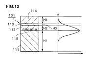
- Patent Document 2 discloses a boundary acoustic wave device 101 schematically shown in Fig. 12 .
- the IDT electrode 115 is disposed at the interface between the first medium 111 made of a Y-cut X-propagation LiNbO 3 substrate and the second medium 112 made of a SiO 2 film.
- a third medium 113 made of a polycrystalline Si layer and a fourth medium 114 made of a SiO 2 film are laminated on the second medium 112 in that order.
- frequency adjustment can be conducted by laminating the second medium 112 to the fourth medium 114. That is, the electrode 115 is formed between the first medium 111 having a film thickness of H1 and the second medium 112 having a film thickness of H2, and the third medium 113 having a film thickness of H3 is laminated, so that a laminate is obtained. The frequency control is conducted at this laminate stage. Then, the fourth medium 114 having a film thickness of H4 is laminated on the third medium 113. Regarding the thus obtained boundary acoustic wave device 101, the energy of the boundary wave becomes as shown in the right-hand part of Fig. 12 . That is, in the fourth medium, the energy is distributed to only a small part.
- Patent Document 1 WO2004-070946
- Patent Document 2 WO2005-093949
- the frequency adjustment in the production stage can easily be conducted by laminating the second medium to the fourth medium, as described above. Therefore, the boundary acoustic wave device exhibiting reduced variations in frequency can be provided.
- the temperature coefficient of resonant frequency TCF shown in Fig. 10 in Patent Document 2 the temperature coefficient of resonant frequency TCF may deteriorate because the above-described third medium layer made of a polycrystalline Si layer is laminated.
- a boundary acoustic wave device is provided, the boundary acoustic wave device being characterized in that a first medium to a fourth medium are laminated in that order and an electrode is disposed at an interface between the first medium and the second medium, wherein the temperature coefficient of delay time TCD of a boundary acoustic wave or a surface acoustic wave in a structure formed by laminating the above-described fourth medium/the second medium/the electrode/the first medium takes on a positive value, the above-described fourth medium or the second medium has a positive temperature coefficient of sound velocity TCV and the above-described first medium has a negative temperature coefficient of sound velocity TCV, and the sound velocity of transverse wave in the above-described third medium is specified to be smaller than the sound velocity of transverse wave in the above-described fourth medium and/or the second medium.
- the first medium is made of a piezoelectric substrate
- the second medium is made of a silicon oxide film
- the third medium is made of a tantalum oxide film or a zinc oxide film
- the fourth medium is made of a silicon oxide film.
- the third medium made of the tantalum oxide film or the zinc oxide film exhibiting the sound velocity of transverse wave smaller than that in the silicon oxide film is disposed between the second medium and the fourth medium made of the silicon oxide film.
- the third medium exhibiting the sound velocity of transverse wave smaller than the sound velocities of transverse waves of the fourth medium and the second medium is disposed, so that a boundary acoustic wave device having a small absolute value of temperature coefficient of delay time TCD and good temperature characteristics can be provided reliably.
- a boundary acoustic wave device is provided, the boundary acoustic wave device being characterized in that a first medium to a fourth medium are laminated in that order and an electrode is disposed at an interface between the first medium and the second medium, wherein the temperature coefficient of delay time TCD of a boundary acoustic wave or a surface acoustic wave in a structure formed by laminating the above-described fourth medium/the second medium/the electrode/the first medium takes on a negative value, the above-described fourth medium or the second medium has a negative temperature coefficient of sound velocity TCV and the above-described first medium has a positive temperature coefficient of sound velocity TCV, and the sound velocity of transverse wave in the third medium is specified to be smaller than the sound velocity of transverse wave in the fourth medium and/or the second medium.
- a boundary acoustic wave device is provided, the boundary acoustic wave device being characterized in that a first medium to a fourth medium are laminated in that order and an electrode is disposed at an interface between the first medium and the second medium, wherein the temperature coefficient of delay time TCD of a boundary acoustic wave or a surface acoustic wave in a structure formed by laminating the above-described fourth medium/the second medium/the electrode/the first medium takes on a positive value, the above-described fourth medium or the second medium has a negative temperature coefficient of sound velocity TCV and the above-described first medium has a positive temperature coefficient of sound velocity TCV, and the sound velocity of transverse wave in the above-described third medium is specified to be faster than the sound velocity of transverse wave in the above-described fourth medium and/or the second medium.
- a boundary acoustic wave device is provided, the boundary acoustic wave device being characterized in that a first medium to a fourth medium are laminated in that order and an electrode is disposed at an interface between the first medium and the second medium, wherein the temperature coefficient of delay time TCD of a boundary acoustic wave or a surface acoustic wave in a structure formed by laminating the above-described fourth medium/the second medium/the electrode/the first medium takes on a negative value, the above-described fourth medium or the second medium has a positive temperature coefficient of sound velocity TCV and the above-described first medium has a negative temperature coefficient of sound velocity TCV, and the sound velocity of transverse wave in the above-described third medium is specified to be faster than the sound velocity of transverse wave in the above-described fourth medium and/or the second medium.
- the above-described first medium is made of a piezoelectric substrate
- the above-described second medium and the fourth medium are made of silicon oxide films
- the above-described third medium is made of a silicon film or a silicon nitride film.
- the third medium made of a silicon film or a silicon nitride film exhibiting the sound velocity of transverse wave faster than that in a silicon oxide film is disposed between the second medium and the fourth medium made of the silicon oxide film.
- the third medium exhibiting the sound velocity of transverse wave faster than the sound velocities of transverse waves in the fourth medium and the second medium is disposed, so that a boundary acoustic wave device having a small absolute value of temperature coefficient of delay time TCD and good temperature characteristics can be provided reliably.
- At least one IDT electrode is disposed as the electrode. That is, a boundary acoustic wave is excited efficiently by the at least one IDT electrode. Therefore, according to the present invention, a boundary acoustic wave device having a good temperature characteristic of delay time can be provided through the use of the boundary acoustic wave.
- the sound velocity of transverse wave in the third medium is specified to be smaller than the sound velocity of transverse wave in the fourth medium and/or the second medium. Therefore, the absolute value of temperature characteristic of delay time TCD can be reduced and a boundary acoustic wave device having good temperature characteristics can be provided. The reason for this is believed to be as described below. The vibration energy tends to concentrate on the low sound velocity medium side easily.
- the vibration energy of the transverse wave in the third medium is specified to be smaller than the sound velocity of transverse wave in the fourth medium and/or the second medium. Consequently, the vibration energy of the transverse wave is also highly distributed into the second medium and the fourth medium, so that the temperature coefficient of delay time TCD of the boundary acoustic wave can be reduced.
- the sound velocity of transverse wave of the third medium is made faster and, thereby, the energy distribution of the transverse wave into the second medium and the fourth medium can be reduced, so that an advantage is achieved.
- a boundary acoustic wave device in which changes in characteristics due to temperature is small can be reliably easily provided.
- Fig. 1 (a) and (b) are a schematic sectional front view of a boundary acoustic wave device according to an embodiment of the present invention and a schematic plan view showing an electrode structure.
- a boundary acoustic wave device 1 includes a laminate 15 in which a first medium 11 to a fourth medium 14 are laminated in that order. Furthermore, an electrode structure shown in Fig. 1 (b) is disposed at an interface between the first medium 11 and the second medium 12. That is, the above-described electrode structure includes an IDT electrode 16 and reflectors 17 and 18 disposed outside the IDT electrode 16 in a propagation direction of a boundary acoustic wave.
- the first medium 11 is made of a 15°Y-cut X-propagation LiNbO 3 substrate.
- the first medium 11 may be formed by using LiNbO 3 substrates having other crystal orientations or other piezoelectric single crystal substrates, e.g., a LiTaO 3 substrate.
- the first medium 11 may be made of other piezoelectric materials, e.g., piezoelectric ceramic, and furthermore be formed having a structure in which a piezoelectric thin film is laminated on an insulating material.
- the second medium 12 is made of a SiO 2 film serving as a silicon oxide film.
- the third medium 13 is made of Ta 2 O 5 serving as a tantalum oxide film.
- the fourth medium 14 is made of a SiO 2 film serving as a silicon oxide film.
- the sound velocity of transverse wave in the third medium 13 made of Ta 2 O 5 is 1,580 m/sec.
- the sound velocity of transverse wave in the second medium and the fourth medium made of SiO 2 is 3,757 m/sec. That is, the sound velocity of transverse wave in the third medium is specified to be smaller than the sound velocity of transverse wave in the second medium 12 and the fourth medium 14.
- the sound velocity of transverse wave in ZnO is 2,826 m/sec and, therefore, ZnO can be used as the third medium.
- the temperature coefficient of delay time TCD of a boundary acoustic wave is specified to be a positive value.
- the temperature coefficient of delay time TCD is an index of a propagation property of an acoustic wave and is directly linked to an index of a device performance.
- the sound velocity of transverse wave in the third medium 13 is specified to be smaller than the sound velocity of transverse wave in the second medium 12 and the sound velocity of transverse wave in the fourth medium 14.
- the sound velocity of transverse wave in the third medium 13 is specified to be smaller than at least one of the sound velocity of transverse wave in the second medium 12 and the sound velocity of transverse wave in the fourth medium 14.
- the temperature coefficient of sound velocity TCV takes on a positive value in the second medium and the fourth medium made of SiO 2 .
- the temperature coefficient of sound velocity TCV is an index of the propagation performance of an acoustic wave except the influence of the coefficient of linear expansion and shows the tendency of changes in sound velocity due to temperature except the influence of the coefficient of linear expansion.
- the temperature coefficient of sound velocity TCV in the LiNbO 3 substrate defining the first medium 11 takes on a negative value.
- the IDT electrode 16 and the reflectors 17 and 18 are made of a laminated metal film in which an Al layer is laminated on a Au layer, and the duty ratio of the IDT electrode is specified to be 0.6.
- the sound velocity of transverse wave in Ta 2 O 5 defining the third medium 13 is smaller than the sound velocity of transverse wave in the second medium 12 and the fourth medium 14 and, therefore, the energy of the transverse wave concentrates on the third medium. Consequently, the absolute value of temperature coefficient of delay time TCD of a boundary acoustic wave which propagates at an interface between the first medium 11 and the second medium 12 can be reduced, and good temperature characteristics can be obtained. This will be described more specifically on the basis of comparisons with a boundary acoustic wave device in related art.
- a boundary acoustic wave device in related art configured as in the boundary acoustic wave device 1 of the above-described embodiment except that the third medium 13 and the fourth medium 14 are not included, an IDT electrode, reflectors, and a first medium and a second medium were formed under the condition shown in Table 1 described below.
- this boundary acoustic wave device in related art the finite element method proposed in " Finite-Element Analysis of Periodically Perturbed Piezoelectric Waveguides" (Transactions of Institute of Electronics and Communication Engineers of Japan, Vol. J68-C No. 1.
- the analysis region was specified to be a portion having a thickness of 8 ⁇ in upward and downward directions of the IDT electrode, and the boundary conditions of the front surface and the back surface of the analysis region were elastically fixed.
- ⁇ 12 /k 0 representing the amount of reflection of boundary wave at a strip and the electromechanical coefficient K 2 were determined on the basis of a method proposed in " Analysis of Excitation Characteristics of Interdigital SAW Transducers Using Coupling Modes Theory" (Institute of Electrons, Information and Communication Engineers of Japan, Technical Report, MW90-62, 1990, pp. 69-74 ).
- the temperature coefficient of delay time TCD was determined from phase velocities V 15°C , V 25°C , and V 35°C at the stop-band lower edge of the short-circuit strip at 15°C, 25°C, and 35°C on the basis of the following formula (1).
- TCD ⁇ s - ( V 35 ⁇ °C - V 15 ⁇ °C ) / V 25 ⁇ °C ⁇ 35 - 15
- ⁇ s represents the coefficient of linear expansion of the LiNbO 3 substrate in a propagation direction of boundary wave.
- Table 1 Configuration example in related art SiO 2/ IDT/15°Y-X LN IDT(Al/Au) thickness 0.050/0.035 ⁇ , duty ratio 0.6 Second medium (SiO 2 ) thickness 8 ⁇ , transverse wave sound velocity 3757 m/sec, positive TCV First medium (15°Y-X LiNbO 3 ) thickness 8 ⁇ , negative TCV
- the configurations of the IDT electrode 16 and the first medium 11 to the fourth medium 14 in the boundary acoustic wave device of the above-described embodiment are collectively shown in Table 3.
- the propagation characteristics were calculated as in the above-described boundary acoustic wave device in related art. The results are shown in Table 4.
- the temperature coefficient of delay time is improved and is 18.7 ppm/°C. That is, although the sound velocity, the electromechanical coefficient K 2 , and the ⁇ 12 /k 0 were changed to some extent, these changes are within practically acceptable ranges. On the other hand, it is clear that the temperature coefficient of delay time TCD is improved significantly, as described above.
- the temperature coefficient of delay time TCD of a boundary acoustic wave is determined on the basis of the balance between the coefficient of linear expansion ⁇ s of the total of the plurality of media defining boundaries and the temperature coefficients of sound velocity TCV in individual media. For example, in the case where the temperature coefficient of delay time TCD of the boundary acoustic wave takes on a positive value, if the vibration energy distribution of the boundary wave is enhanced in a material in which the temperature coefficient of sound velocity TCV of transverse wave takes on a positive value, the temperature coefficient of delay time TCD of the boundary wave is reduced. The vibration energy of the boundary acoustic wave easily concentrates on a medium exhibiting a low sound velocity.
- a low sound velocity material may be used for one layer. Furthermore, in the case where one medium is separated into two layers and a relatively low sound velocity medium is inserted between the separated two layers, the vibration energy is concentrated on the low sound velocity medium and, thereby, the vibration energy distribution into the above-described separated two layers is enhanced.
- the temperature coefficient of delay time TCD takes on positive values. Therefore, it is believed that if the vibration energy on the SiO 2 layer side exhibiting the positive temperature coefficient of sound velocity TCV can be enhanced, the temperature coefficient of delay time TCD can be improved. Consequently, in the above-described embodiment, as shown in Table 3, Ta 2 O 5 serving as the third medium in which the sound velocity of transverse wave is relatively low is disposed between the SiO 2 layers defining the second medium and the fourth medium. Therefore, the vibration energy of boundary wave in the second medium 12 and the fourth medium 14 made of SiO 2 exhibiting a positive temperature coefficient of sound velocity TCV can be enhanced.
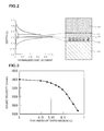
- Fig. 2 is a schematic diagram showing the displacement distributions of boundary acoustic waves in the case of the above-described embodiment and in the case of related art where, in contrast to the above-described embodiment, the third medium made of Ta 2 O 5 is not disposed.
- a solid line indicates the case of the above-described embodiment and a broken line indicates the case of related art.
- the vibration energy of the boundary acoustic wave in the second medium 12 and the fourth medium 14 is enhanced significantly by disposing the third medium 13 made of Ta 2 O 5 .
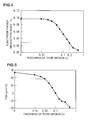
- Fig. 3 to Fig. 6 are diagrams showing the relationships between the thickness of the third medium 13 and the boundary acoustic wave propagation characteristics. Specifically, Fig. 3 is a diagram showing changes in sound velocity in the case where the film thickness of the third medium 13 is changed. Fig. 4 is a diagram showing changes in strip reflection index. Fig. 5 is a diagram showing changes in temperature coefficient of delay time TCD. Fig. 6 is a diagram showing changes in electromechanical coefficient K 2 (%).
- Fig. 7 is a schematic diagram showing the vibration energy distribution in the third medium made of Ta 2 O 5 having a thickness of 0.03 ⁇ .
- Fig. 8 is a schematic diagram showing the vibration energy distribution in the third medium made of Ta 2 O 5 having a thickness of 0.20 ⁇ .
- the thickness of the third medium increases, the influence of the low sound velocity third medium increases and, thereby, the sound velocity of the boundary acoustic wave is reduced.
- the sound velocity is 3,394 m/s, whereas in the case where the thickness of the third medium is 0.03 ⁇ , the sound velocity becomes 3,332 m/s.
- the temperature coefficient of delay time TCD shifts to the negative side, as shown in Fig. 5 , on the basis of the above-described principle.
- TCD is 27 ppm/°C in the case where the third medium is not disposed, whereas TCD becomes 18 ppm/°C in the case where the thickness of the third medium is 0.03 ⁇ .
- the vibration energy distributed into the LiNbO 3 substrate decreases, and the electromechanical coefficient K 2 is reduced. That is, in the case where the thickness of the Ta 2 O 5 is 0.3 ⁇ , as is clear from Fig. 6 , the electromechanical coefficient K 2 is reduced to 2.4% and, therefore, the usability is deteriorated.
- the thickness of the third medium 13 made of Ta 2 O 5 is preferably 0.30 ⁇ or less, and more preferably 0.20 ⁇ or less.
- a one-port type boundary acoustic wave device was specifically prepared following the above-described embodiment, and the temperature coefficient of resonant frequency TCF and the ratio of the band width to the frequency were measured.
- the period ⁇ of the IDT electrode 16, the configuration and the thickness of the IDT electrode 16, the film thicknesses and materials of the first medium 11 to the fourth medium 14 were set as shown in Table 5 described below.
- design parameters of the IDT electrode 16 were specified as described below.
- the number of pairs of electrode fingers 60 pairs Intersection width: 30 ⁇ Opening width: 30.4 ⁇ Apodization: presence, intersection width of center of IDT 30 ⁇ , intersection width of both ends of IDT 15 ⁇
- the number of electrode fingers of reflector 51 fingers Period of IDT and reflector ⁇ : 3.42 ⁇ m (electrode fingers disposition pitch 0.8 ⁇ m) Line width of electrode fingers: 0.855 ⁇ m Space width between electrode fingers: 0.855 ⁇ m [Table 5] Item Dimension IDT period ⁇ 3.42 ⁇ m IDT(NiCr/Ti/AI/Ti/Ni/Au/Ni/Ti) thickness 20/20/100/20/20/140/20/20 nm Fourth medium (SiO 2 ) thickness 6000 nm Third medium (Ta 2 O 5 ) thickness 170 nm Second medium (SiO 2 ) thickness 680 nm First medium (15°Y-X LiNbO 3 ) thickness 500 ⁇ m
- the thickness of the third medium 13 was specified to be 170 nm, that is, 0.05 ⁇ .
- a boundary acoustic wave device of a modified example was prepared, in which the thickness of the third medium 13 was specified to be 0.02 ⁇ (68 nm).
- a boundary acoustic wave device was prepared as in the above-described prototype example except that the thickness of the third medium was 0 ⁇ , that is, the third medium 13 was not disposed.
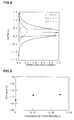
- the temperature coefficient of resonant frequency TCF and the ratio of the band width to the frequency were measured. The results are shown in Fig. 9 and Fig. 10 .
- the ratio of the band width to the frequency was determined from (anti-resonant frequency - resonant frequency)/resonant frequency.
- the absolute values of the temperature coefficients of resonant frequency TCF can be reduced as compared with that of the boundary acoustic wave device not including the third medium, and the ratio of the band width to the frequency does not change significantly. Therefore, it is clear that the frequency temperature characteristic can be improved without reducing the ratio of the band width to the frequency.
- Fig. 11 is a diagram showing the impedance and the phase characteristics of three types of boundary acoustic wave devices prepared as described above.
- the impedance ratio that is, the top-to-valley ratio, which is a ratio of the impedance at an anti-resonant frequency to the impedance at a resonant frequency becomes large as compared with that of the comparative example in which the third medium is not included and, therefore, the characteristics are improved.
- the temperature coefficient of resonant frequency TCF of the device can be corrected to the positive side by using a material having a positive temperature coefficient of sound velocity TCV for the second medium 12 and the fourth medium 14.
- the usability can be enhanced by using SiO 2 having a positive temperature coefficient of sound velocity TCV as the second medium 12 and the fourth medium 14. That is, the absolute value of temperature coefficient of resonant frequency TCF can be reduced.
- Ta 2 O 5 exhibits a low sound velocity, and is a heavy, hard dielectric material.
- the energy can be moved from the first medium 11 to the second medium 12 side.
- SiO 2 and Ta 2 O 5 exhibit excellent heat resistance and are chemically stable. Consequently, the boundary acoustic wave device 1 of the above-described embodiment not only exhibits small changes in characteristics due to temperature, but also exhibits excellent heat resistance and stability. In addition, the reliability is also excellent.
- the second medium 12 and the fourth medium 14 may be made of different materials.
- the temperature coefficient of delay time TCD of the boundary acoustic wave takes on a positive value in the structure in which the fourth medium/the second medium/the electrode/the first medium are laminated.
- the fourth medium or the second medium have a positive temperature coefficient of sound velocity TCV and the first medium has a negative temperature coefficient of sound velocity TCV.
- the present invention is not limited to such a structure.
- the delay time temperature characteristic can also be improved in the following second structure in which the sound velocity of transverse wave in the third medium is specified to be smaller than that in the fourth medium and/or the second medium, and in the third and fourth structures in which, conversely, the sound velocity of transverse wave in the third medium is specified to be faster.
- Second structural example a structure in which the temperature coefficient of delay time TCD of the boundary acoustic wave takes on a negative value in the laminated structure of the fourth medium/the second medium/the electrode/the first medium, the fourth medium or the second medium has a negative temperature coefficient of sound velocity TCV, and the first medium has a positive temperature coefficient of sound velocity TCV.
- Third structural example a structure in which the temperature coefficient of delay time TCD of the boundary acoustic wave takes on a positive value in the laminated structure of the fourth medium/the second medium/the electrode/the first medium, the fourth medium or the second medium has a negative temperature coefficient of sound velocity TCV, and the first medium has a positive temperature coefficient of sound velocity TCV.
- Fourth structural example a structure in which the temperature coefficient of delay time TCD of the boundary acoustic wave takes on a negative value in the laminated structure of the fourth medium/the second medium/the electrode/the first medium, the fourth medium or the second medium has a positive temperature coefficient of sound velocity TCV, and the first medium has a negative temperature coefficient of sound velocity TCV.
- the boundary acoustic wave device can be configured to have various electrode structures. That is, the boundary acoustic wave device may be a longitudinally coupled or transversely coupled boundary acoustic wave resonator filter including at least two IDTs or a ladder filter in which a plurality of boundary acoustic wave resonators are connected in a ladder arrangement.
- the acoustic wave device according to the present invention can be used for optical devices, e.g., boundary acoustic wave optical switches and boundary acoustic wave optical filters, and be widely used for general devices taking advantage of the boundary acoustic wave.
- optical devices e.g., boundary acoustic wave optical switches and boundary acoustic wave optical filters
- the thicknesses of the IDT electrode 16, the second medium 12, and/or the third medium 13 can be adjusted by reducing the thicknesses of the IDT electrode and the second medium 12 or the third medium 13 through reverse sputtering, ion beam milling, reactive ion etching, wet etching, polishing, or the like or by increasing the thickness through additional film formation by sputtering or a deposition method, e.g., evaporation.
- the electrode structure may be made of a laminated film composed of a plurality of metals.
- the materials for defining the first medium to the fourth medium in the present invention are not specifically limited. That is, various dielectric materials can be used as the media. Examples of such media include one type selected from the group consisting of lithium niobate, potassium niobate, lithium tantalate, lithium tetraborate, langasite, langanite, quartz, PZT, ZnO, AIN, silicon oxide, glass, silicon, sapphire, silicon nitride, and carbon nitride.
- the medium is not necessarily made of a single material, but may have a laminated structure in which a plurality of medium layers are laminated. That is, at least one medium of the first medium to the fourth medium may have a laminated structure in which a plurality of material layers are laminated.
- boundary acoustic wave device may be provided with an external protective layer for enhancing strength and preventing infiltration of corrosive gases and the like.
- the boundary acoustic wave device may have a structure of being enclosed in a package in a case where size reduction is not required.
- the above-described protective layer may be made of insulating materials, e.g., titanium oxide, aluminum nitride, and aluminum oxide, be made of metal films of Au, Al, W, and the like, and be made of resin films of epoxy resins and the like.
Landscapes
- Physics & Mathematics (AREA)
- Acoustics & Sound (AREA)
- Surface Acoustic Wave Elements And Circuit Networks Thereof (AREA)
Abstract
Description
- The present invention relates to a boundary acoustic wave device used as, for example, a resonator and a filter. In particular, the present invention relates to a boundary acoustic wave device having a structure in which an electrode is disposed between a first medium and a second medium, and a third medium and a fourth medium are further laminated on the second medium.
- In recent years, boundary acoustic wave devices have been noted as resonators and band pass filters because package structures can be simplified.
- The following
Patent Document 1 discloses a boundary acoustic wave device, wherein the electromechanical coefficient is large, the propagation loss and the power flow angle are small, and the temperature coefficient of resonant frequency TCF is within an appropriate range. Here, an IDT electrode is disposed at an interface between a first medium made of a piezoelectric substrate and a second medium made of a SiO2 film. Furthermore, it is described that the electromechanical coefficient and the temperature characteristics can be adjusted by adjusting the crystal orientation of a piezoelectric single crystal used as the piezoelectric substrate, the material for defining the IDT electrode, the film thickness, and the electrode finger pitch. - On the other hand, the following
Patent Document 2 discloses a boundaryacoustic wave device 101 schematically shown inFig. 12 . In the boundaryacoustic wave device 101, theIDT electrode 115 is disposed at the interface between thefirst medium 111 made of a Y-cut X-propagation LiNbO3 substrate and thesecond medium 112 made of a SiO2 film. Furthermore, athird medium 113 made of a polycrystalline Si layer and afourth medium 114 made of a SiO2 film are laminated on thesecond medium 112 in that order. - Here, it is described that frequency adjustment can be conducted by laminating the
second medium 112 to thefourth medium 114. That is, theelectrode 115 is formed between thefirst medium 111 having a film thickness of H1 and thesecond medium 112 having a film thickness of H2, and thethird medium 113 having a film thickness of H3 is laminated, so that a laminate is obtained. The frequency control is conducted at this laminate stage. Then, thefourth medium 114 having a film thickness of H4 is laminated on thethird medium 113. Regarding the thus obtained boundaryacoustic wave device 101, the energy of the boundary wave becomes as shown in the right-hand part ofFig. 12 . That is, in the fourth medium, the energy is distributed to only a small part. Therefore, according to the description, in the case where the frequency control is conducted at the above-described laminate stage and variations in frequency are reduced significantly, even when thefourth medium 114 is formed, it is possible to reduce variations in frequency.
Patent Document 1:WO2004-070946
Patent Document 2:WO2005-093949 - In the boundary acoustic wave device described in
Patent Document 1, when the substrate crystal orientation of the piezoelectric single crystal defining the piezoelectric substrate and the configuration of the IDT electrode are determined, the temperature coefficient of resonant frequency TCF and the temperature coefficient of delay time TCD are determined automatically. Therefore, it is difficult to obtain a boundary acoustic wave device having desired temperature characteristics. - On the other hand, in the boundary acoustic wave device described in
Patent Document 2, the frequency adjustment in the production stage can easily be conducted by laminating the second medium to the fourth medium, as described above. Therefore, the boundary acoustic wave device exhibiting reduced variations in frequency can be provided. However, as is clear from the temperature coefficient of resonant frequency TCF shown inFig. 10 inPatent Document 2, the temperature coefficient of resonant frequency TCF may deteriorate because the above-described third medium layer made of a polycrystalline Si layer is laminated. - In consideration of the above-described current state of the technology in related art, it is an object of the present invention to provide a boundary acoustic wave device formed by laminating a plurality of media, wherein changes in characteristics due to temperature are small.
- According to a first invention of the present invention, a boundary acoustic wave device is provided, the boundary acoustic wave device being characterized in that a first medium to a fourth medium are laminated in that order and an electrode is disposed at an interface between the first medium and the second medium, wherein the temperature coefficient of delay time TCD of a boundary acoustic wave or a surface acoustic wave in a structure formed by laminating the above-described fourth medium/the second medium/the electrode/the first medium takes on a positive value, the above-described fourth medium or the second medium has a positive temperature coefficient of sound velocity TCV and the above-described first medium has a negative temperature coefficient of sound velocity TCV, and the sound velocity of transverse wave in the above-described third medium is specified to be smaller than the sound velocity of transverse wave in the above-described fourth medium and/or the second medium.
- In a specific aspect of the present invention, the first medium is made of a piezoelectric substrate, the second medium is made of a silicon oxide film, the third medium is made of a tantalum oxide film or a zinc oxide film, and the fourth medium is made of a silicon oxide film. In this case, the third medium made of the tantalum oxide film or the zinc oxide film exhibiting the sound velocity of transverse wave smaller than that in the silicon oxide film is disposed between the second medium and the fourth medium made of the silicon oxide film. Therefore, according to the present invention, the third medium exhibiting the sound velocity of transverse wave smaller than the sound velocities of transverse waves of the fourth medium and the second medium is disposed, so that a boundary acoustic wave device having a small absolute value of temperature coefficient of delay time TCD and good temperature characteristics can be provided reliably.
- According to a second invention of the present invention, a boundary acoustic wave device is provided, the boundary acoustic wave device being characterized in that a first medium to a fourth medium are laminated in that order and an electrode is disposed at an interface between the first medium and the second medium, wherein the temperature coefficient of delay time TCD of a boundary acoustic wave or a surface acoustic wave in a structure formed by laminating the above-described fourth medium/the second medium/the electrode/the first medium takes on a negative value, the above-described fourth medium or the second medium has a negative temperature coefficient of sound velocity TCV and the above-described first medium has a positive temperature coefficient of sound velocity TCV, and the sound velocity of transverse wave in the third medium is specified to be smaller than the sound velocity of transverse wave in the fourth medium and/or the second medium.
- According to a third invention of the present invention, a boundary acoustic wave device is provided, the boundary acoustic wave device being characterized in that a first medium to a fourth medium are laminated in that order and an electrode is disposed at an interface between the first medium and the second medium, wherein the temperature coefficient of delay time TCD of a boundary acoustic wave or a surface acoustic wave in a structure formed by laminating the above-described fourth medium/the second medium/the electrode/the first medium takes on a positive value, the above-described fourth medium or the second medium has a negative temperature coefficient of sound velocity TCV and the above-described first medium has a positive temperature coefficient of sound velocity TCV, and the sound velocity of transverse wave in the above-described third medium is specified to be faster than the sound velocity of transverse wave in the above-described fourth medium and/or the second medium.
- According to a fourth invention of the present invention, a boundary acoustic wave device is provided, the boundary acoustic wave device being characterized in that a first medium to a fourth medium are laminated in that order and an electrode is disposed at an interface between the first medium and the second medium, wherein the temperature coefficient of delay time TCD of a boundary acoustic wave or a surface acoustic wave in a structure formed by laminating the above-described fourth medium/the second medium/the electrode/the first medium takes on a negative value, the above-described fourth medium or the second medium has a positive temperature coefficient of sound velocity TCV and the above-described first medium has a negative temperature coefficient of sound velocity TCV, and the sound velocity of transverse wave in the above-described third medium is specified to be faster than the sound velocity of transverse wave in the above-described fourth medium and/or the second medium.
- In the fourth invention, preferably, the above-described first medium is made of a piezoelectric substrate, the above-described second medium and the fourth medium are made of silicon oxide films, and the above-described third medium is made of a silicon film or a silicon nitride film. In this case, the third medium made of a silicon film or a silicon nitride film exhibiting the sound velocity of transverse wave faster than that in a silicon oxide film is disposed between the second medium and the fourth medium made of the silicon oxide film. Therefore, according to the present invention, the third medium exhibiting the sound velocity of transverse wave faster than the sound velocities of transverse waves in the fourth medium and the second medium is disposed, so that a boundary acoustic wave device having a small absolute value of temperature coefficient of delay time TCD and good temperature characteristics can be provided reliably.
- In the present invention (the first invention to the fourth invention), preferably, at least one IDT electrode is disposed as the electrode. That is, a boundary acoustic wave is excited efficiently by the at least one IDT electrode. Therefore, according to the present invention, a boundary acoustic wave device having a good temperature characteristic of delay time can be provided through the use of the boundary acoustic wave.
- In the boundary acoustic wave device according to the present invention (the first invention and the second invention), in the structure in which the first medium to the fourth medium are laminated in that order and the electrode is disposed at the interface between the first medium and the second medium, the sound velocity of transverse wave in the third medium is specified to be smaller than the sound velocity of transverse wave in the fourth medium and/or the second medium. Therefore, the absolute value of temperature characteristic of delay time TCD can be reduced and a boundary acoustic wave device having good temperature characteristics can be provided. The reason for this is believed to be as described below. The vibration energy tends to concentrate on the low sound velocity medium side easily. Therefore, in the case where the sound velocity of transverse wave in the third medium is specified to be smaller than the sound velocity of transverse wave in the fourth medium and/or the second medium, the vibration energy of the transverse wave is highly distributed into the third medium. Consequently, the vibration energy of the transverse wave is also highly distributed into the second medium and the fourth medium, so that the temperature coefficient of delay time TCD of the boundary acoustic wave can be reduced. In the third invention and the fourth invention, conversely, the sound velocity of transverse wave of the third medium is made faster and, thereby, the energy distribution of the transverse wave into the second medium and the fourth medium can be reduced, so that an advantage is achieved.
- Therefore, according to the present invention, a boundary acoustic wave device in which changes in characteristics due to temperature is small can be reliably easily provided.
-
- [
Fig. 1] Fig. 1 (a) and (b) are a schematic sectional front view for explaining a boundary acoustic wave device according to an embodiment of the present invention and a schematic plan view showing an electrode structure. - [
Fig. 2] Fig. 2 is a schematic diagram for explaining vibration energy distribution states in individual medium layers in a boundary acoustic wave device of an embodiment. - [
Fig. 3] Fig. 3 is a diagram showing changes in sound velocity of a boundary acoustic wave in the case where the film thickness of the third medium made of Ta2O5 is changed. - [
Fig. 4] Fig. 4 is a diagram showing changes in electrode finger reflection index κ12 of a boundary acoustic wave in the case where the film thickness of the third medium made of Ta2O5 is changed. - [
Fig. 5] Fig. 5 is a diagram showing changes in temperature coefficient of delay time TCD of a boundary acoustic wave in the case where the film thickness of the third medium made of Ta2O5 is changed. - [
Fig. 6] Fig. 6 is a diagram showing changes in electromechanical coefficient K2 of a boundary acoustic wave in the case where the film thickness of the third medium made of Ta2O5 is changed. - [
Fig. 7] Fig. 7 is a diagram schematically showing the vibration energy distribution of a boundary acoustic wave device of an embodiment in the case where the thickness of Ta2O5 defining the third medium is 0.03 λ. - [
Fig. 8] Fig. 8 is a diagram schematically showing the vibration energy distribution of a boundary acoustic wave device of an embodiment in the case where the thickness of Ta2O5 defining the third medium is 0.20 λ. - [
Fig. 9] Fig. 9 is a diagram showing the temperature coefficients of resonant frequency TCF in the case where the thickness of the third medium made of Ta2O5 is 0.02 λ and 0.05 λ and in a structure in which the third medium is not laminated. - [
Fig. 10] Fig. 10 is a diagram showing the ratios of band width to the frequency of a resonator in the case where the thickness of the third medium made of Ta2O5 is 0.02 λ and 0.05 λ and in a structure in which the third medium is not laminated. - [
Fig. 11] Fig. 11 is a diagram showing the impedance frequency characteristic and the phase frequency characteristic of individual boundary acoustic wave devices in which the thickness of Ta2O5 serving as the third medium is 0.02 λ, the thickness is 0.05 λ, or the third medium is not laminated. - [
Fig. 12] Fig. 12 is a schematic sectional front view for explaining an example of boundary acoustic wave devices in related art. -
- 1
- boundary acoustic wave device
- 11
- first medium
- 12
- second medium
- 13
- third medium
- 14
- fourth medium
- 15
- laminate
- 16
- IDT electrode
- 17, 18
- reflector
- The specific embodiments according to the present invention will be described below with reference to the drawings to make clear the present invention.
-
Fig. 1 (a) and (b) are a schematic sectional front view of a boundary acoustic wave device according to an embodiment of the present invention and a schematic plan view showing an electrode structure. - A boundary
acoustic wave device 1 includes a laminate 15 in which a first medium 11 to a fourth medium 14 are laminated in that order. Furthermore, an electrode structure shown inFig. 1 (b) is disposed at an interface between thefirst medium 11 and thesecond medium 12. That is, the above-described electrode structure includes anIDT electrode 16 andreflectors IDT electrode 16 in a propagation direction of a boundary acoustic wave. - In the present embodiment, the
first medium 11 is made of a 15°Y-cut X-propagation LiNbO3 substrate. The first medium 11 may be formed by using LiNbO3 substrates having other crystal orientations or other piezoelectric single crystal substrates, e.g., a LiTaO3 substrate. The first medium 11 may be made of other piezoelectric materials, e.g., piezoelectric ceramic, and furthermore be formed having a structure in which a piezoelectric thin film is laminated on an insulating material. - In the present embodiment, the
second medium 12 is made of a SiO2 film serving as a silicon oxide film. In the present embodiment, the third medium 13 is made of Ta2O5 serving as a tantalum oxide film. Thefourth medium 14 is made of a SiO2 film serving as a silicon oxide film. - The sound velocity of transverse wave in the third medium 13 made of Ta2O5 is 1,580 m/sec. On the other hand, the sound velocity of transverse wave in the second medium and the fourth medium made of SiO2 is 3,757 m/sec. That is, the sound velocity of transverse wave in the third medium is specified to be smaller than the sound velocity of transverse wave in the
second medium 12 and thefourth medium 14. Furthermore, the sound velocity of transverse wave in ZnO is 2,826 m/sec and, therefore, ZnO can be used as the third medium. - In the laminated structure in which the above-described fourth medium 14/the second medium 12/ the
IDT electrode 16/the first medium 11 are laminated, the temperature coefficient of delay time TCD of a boundary acoustic wave is specified to be a positive value. Incidentally, the temperature coefficient of delay time TCD is an index of a propagation property of an acoustic wave and is directly linked to an index of a device performance. The relationship with the temperature coefficient of resonant frequency TCF serving as an index of the device performance is represented by TCF = -TCD. - In the present embodiment, the sound velocity of transverse wave in the third medium 13 is specified to be smaller than the sound velocity of transverse wave in the
second medium 12 and the sound velocity of transverse wave in thefourth medium 14. However, it is enough that the sound velocity of transverse wave in the third medium 13 is specified to be smaller than at least one of the sound velocity of transverse wave in thesecond medium 12 and the sound velocity of transverse wave in thefourth medium 14. - The temperature coefficient of sound velocity TCV takes on a positive value in the second medium and the fourth medium made of SiO2. The temperature coefficient of sound velocity TCV is an index of the propagation performance of an acoustic wave except the influence of the coefficient of linear expansion and shows the tendency of changes in sound velocity due to temperature except the influence of the coefficient of linear expansion.
- The temperature coefficient of sound velocity TCV in the LiNbO3 substrate defining the
first medium 11 takes on a negative value. - In the present embodiment, the
IDT electrode 16 and thereflectors - In the boundary
acoustic wave device 1 of the present embodiment, the sound velocity of transverse wave in Ta2O5 defining the third medium 13 is smaller than the sound velocity of transverse wave in thesecond medium 12 and thefourth medium 14 and, therefore, the energy of the transverse wave concentrates on the third medium. Consequently, the absolute value of temperature coefficient of delay time TCD of a boundary acoustic wave which propagates at an interface between thefirst medium 11 and the second medium 12 can be reduced, and good temperature characteristics can be obtained. This will be described more specifically on the basis of comparisons with a boundary acoustic wave device in related art. - Regarding a boundary acoustic wave device in related art configured as in the boundary
acoustic wave device 1 of the above-described embodiment except that the third medium 13 and the fourth medium 14 are not included, an IDT electrode, reflectors, and a first medium and a second medium were formed under the condition shown in Table 1 described below. Regarding this boundary acoustic wave device in related art, the finite element method proposed in "Finite-Element Analysis of Periodically Perturbed Piezoelectric Waveguides" (Transactions of Institute of Electronics and Communication Engineers of Japan, Vol. J68-C No. 1. 1985/1 pp 21-27) was expanded, one strip (electrode finger) is disposed within a half-wavelength interval, and the sound velocities at an upper edge and a lower edge of a stop band of an electrically open-circuit strip and a short-circuit strip were determined. Most of the vibration energy of boundary wave concentrates on a portion from 1 λ above the IDT electrode to 1 λ below the IDT electrode. Therefore, the analysis region was specified to be a portion having a thickness of 8 λ in upward and downward directions of the IDT electrode, and the boundary conditions of the front surface and the back surface of the analysis region were elastically fixed. - Subsequently, κ12/k0 representing the amount of reflection of boundary wave at a strip and the electromechanical coefficient K2 were determined on the basis of a method proposed in "Analysis of Excitation Characteristics of Interdigital SAW Transducers Using Coupling Modes Theory" (Institute of Electrons, Information and Communication Engineers of Japan, Technical Report, MW90-62, 1990, pp. 69-74). Since the frequency dispersion of sound velocity in the above-described boundary acoustic wave device prepared as an example of devices in related art was large as compared with that of the structure dealt with in "Finite-Element Analysis of Periodically Perturbed Piezoelectric Waveguides", the κ12/k0 was determined in consideration of the influence of the frequency dispersion.
- The temperature coefficient of delay time TCD was determined from phase velocities V15°C, V25°C, and V35°C at the stop-band lower edge of the short-circuit strip at 15°C, 25°C, and 35°C on the basis of the following formula (1).

- In Formula (1), αs represents the coefficient of linear expansion of the LiNbO3 substrate in a propagation direction of boundary wave.
[Table 1] Configuration example in related art SiO2/IDT/15°Y-X LN IDT(Al/Au) thickness 0.050/0.035 λ, duty ratio 0.6 Second medium (SiO2) thickness 8 λ, transverse wave sound velocity 3757 m/sec, positive TCV First medium (15°Y-X LiNbO3) thickness 8 λ, negative TCV - The characteristics of the boundary acoustic wave device in related art determined by the above-described calculation are shown in Table 2 described below.
[Table 2] Item Propagation characteristics Sound velocity V25°C 3495 m/sec TCD 26.8 ppm/°C K2 17.4% κ12/k0 0.096 - On the other hand, the configurations of the
IDT electrode 16 and the first medium 11 to the fourth medium 14 in the boundary acoustic wave device of the above-described embodiment are collectively shown in Table 3. Regarding the boundary acoustic wave device of the above-described embodiment set as shown in Table 3 described below, the propagation characteristics were calculated as in the above-described boundary acoustic wave device in related art. The results are shown in Table 4.[Table 3] Embodiment SiO2/Ta2O5/SiO2/IDT/15°Y-X LN IDT(Al/Au) thickness 0.050/0.035 λ, duty ratio 0.6 Fourth medium (SiO2) thickness 8 λ, transverse wave sound velocity 3757 m/sec, positive TCV Third medium (Ta2O5) thickness 0.03 λ, transverse wave sound velocity 1580 m/sec Second medium (SiO2) thickness 0.2 λ, transverse wave sound velocity 3757 m/sec, positive TCV First medium (15°Y-X LiNbO3) thickness 8 λ, negative TCV [Table 4] Item Propagation characteristics Sound velocity V25°C 3332 m/sec TCD 18.7 ppm/°C K2 15.1% κ12/k0 0.091 - As is clear from comparisons between Table 2 and Table 4, according to the boundary acoustic wave device of the present embodiment, the temperature coefficient of delay time is improved and is 18.7 ppm/°C. That is, although the sound velocity, the electromechanical coefficient K2, and the κ12/k0 were changed to some extent, these changes are within practically acceptable ranges. On the other hand, it is clear that the temperature coefficient of delay time TCD is improved significantly, as described above.
- The reason for reduction of absolute value and improvement of the temperature coefficient of delay time TCD is believed to be as described below.
- The temperature coefficient of delay time TCD of a boundary acoustic wave is determined on the basis of the balance between the coefficient of linear expansion αs of the total of the plurality of media defining boundaries and the temperature coefficients of sound velocity TCV in individual media. For example, in the case where the temperature coefficient of delay time TCD of the boundary acoustic wave takes on a positive value, if the vibration energy distribution of the boundary wave is enhanced in a material in which the temperature coefficient of sound velocity TCV of transverse wave takes on a positive value, the temperature coefficient of delay time TCD of the boundary wave is reduced. The vibration energy of the boundary acoustic wave easily concentrates on a medium exhibiting a low sound velocity. Therefore, in the case where it is desired to concentrate the vibration energy of the boundary acoustic wave on one layer of the two layers, a low sound velocity material may be used for one layer. Furthermore, in the case where one medium is separated into two layers and a relatively low sound velocity medium is inserted between the separated two layers, the vibration energy is concentrated on the low sound velocity medium and, thereby, the vibration energy distribution into the above-described separated two layers is enhanced.
- In the boundary acoustic wave device in related art shown in Table 1, the temperature coefficient of delay time TCD takes on positive values. Therefore, it is believed that if the vibration energy on the SiO2 layer side exhibiting the positive temperature coefficient of sound velocity TCV can be enhanced, the temperature coefficient of delay time TCD can be improved. Consequently, in the above-described embodiment, as shown in Table 3, Ta2O5 serving as the third medium in which the sound velocity of transverse wave is relatively low is disposed between the SiO2 layers defining the second medium and the fourth medium. Therefore, the vibration energy of boundary wave in the
second medium 12 and the fourth medium 14 made of SiO2 exhibiting a positive temperature coefficient of sound velocity TCV can be enhanced. -
Fig. 2 is a schematic diagram showing the displacement distributions of boundary acoustic waves in the case of the above-described embodiment and in the case of related art where, in contrast to the above-described embodiment, the third medium made of Ta2O5 is not disposed. A solid line indicates the case of the above-described embodiment and a broken line indicates the case of related art. As is clear fromFig. 2 , the vibration energy of the boundary acoustic wave in thesecond medium 12 and thefourth medium 14 is enhanced significantly by disposing the third medium 13 made of Ta2O5. -
Fig. 3 to Fig. 6 are diagrams showing the relationships between the thickness of the third medium 13 and the boundary acoustic wave propagation characteristics. Specifically,Fig. 3 is a diagram showing changes in sound velocity in the case where the film thickness of the third medium 13 is changed.Fig. 4 is a diagram showing changes in strip reflection index.Fig. 5 is a diagram showing changes in temperature coefficient of delay time TCD.Fig. 6 is a diagram showing changes in electromechanical coefficient K2 (%). -
Fig. 7 is a schematic diagram showing the vibration energy distribution in the third medium made of Ta2O5 having a thickness of 0.03 λ.Fig. 8 is a schematic diagram showing the vibration energy distribution in the third medium made of Ta2O5 having a thickness of 0.20 λ. - As is clear from
Fig. 3 , in the case where the thickness of the third medium (Ta2O5) increases, the influence of the low sound velocity third medium increases and, thereby, the sound velocity of the boundary acoustic wave is reduced. For example, in the case where the third medium is not disposed, the sound velocity is 3,394 m/s, whereas in the case where the thickness of the third medium is 0.03 λ, the sound velocity becomes 3,332 m/s. Furthermore, if the thickness of the third medium (Ta2O5) increases, the temperature coefficient of delay time TCD shifts to the negative side, as shown inFig. 5 , on the basis of the above-described principle. For example, TCD is 27 ppm/°C in the case where the third medium is not disposed, whereas TCD becomes 18 ppm/°C in the case where the thickness of the third medium is 0.03 λ. Moreover, as shown inFig. 7 andFig. 8 , as the thickness of Ta2O5 increases to 0.20 λ, the vibration energy distributed into the LiNbO3 substrate decreases, and the electromechanical coefficient K2 is reduced. That is, in the case where the thickness of the Ta2O5 is 0.3 λ, as is clear fromFig. 6 , the electromechanical coefficient K2 is reduced to 2.4% and, therefore, the usability is deteriorated. - Furthermore, as is clear from
Fig. 4 , as the thickness of the third medium 13 made of Ta2O5 increases, the κ12 indicating the reflection coefficient of the strip is reduced. In particular, when the thickness of Ta2O5 is 0.2 λ, the κ12 becomes a small 0.026. Therefore, if the κ12 becomes less than 0.026, it is necessary to increase the number of reflector regarding the one-port type boundary acoustic wave resonator of the above-described embodiment in whichstrip type reflectors IDT electrode 16. And, in the case where a longitudinally coupled resonator filter is provided, which is a boundary acoustic wave device using a resonator structure, the number of reflector is increased. Consequently, unfavorably, size increasing of the boundary acoustic wave device occurs. Therefore, it is desirable that the thickness of the third medium 13 made of Ta2O5 is preferably 0.30λ or less, and more preferably 0.20 λ or less. - Next, a one-port type boundary acoustic wave device was specifically prepared following the above-described embodiment, and the temperature coefficient of resonant frequency TCF and the ratio of the band width to the frequency were measured.
- That is, the period λ of the
IDT electrode 16, the configuration and the thickness of theIDT electrode 16, the film thicknesses and materials of the first medium 11 to the fourth medium 14 were set as shown in Table 5 described below. - Furthermore, the design parameters of the
IDT electrode 16 were specified as described below. - The number of pairs of electrode fingers: 60 pairs
Intersection width: 30 λ
Opening width: 30.4 λ
Apodization: presence, intersection width of center ofIDT 30 λ, intersection width of both ends ofIDT 15 λ - The number of electrode fingers of reflector: 51 fingers
Period of IDT and reflector λ: 3.42 µm (electrode fingers disposition pitch 0.8 µm)
Line width of electrode fingers: 0.855 µm
Space width between electrode fingers: 0.855 µm[Table 5] Item Dimension IDT period λ 3.42 µm IDT(NiCr/Ti/AI/Ti/Ni/Au/Ni/Ti) thickness 20/20/100/20/20/140/20/20 nmFourth medium (SiO2) thickness 6000 nm Third medium (Ta2O5) thickness 170 nm Second medium (SiO2) thickness 680 nm First medium (15°Y-X LiNbO3) thickness 500 µm - The thickness of the third medium 13 was specified to be 170 nm, that is, 0.05 λ. However, in addition, a boundary acoustic wave device of a modified example was prepared, in which the thickness of the third medium 13 was specified to be 0.02 λ (68 nm). Furthermore, for the purposes of comparison, a boundary acoustic wave device was prepared as in the above-described prototype example except that the thickness of the third medium was 0 λ, that is, the third medium 13 was not disposed. Regarding these boundary acoustic wave devices, the temperature coefficient of resonant frequency TCF and the ratio of the band width to the frequency were measured. The results are shown in
Fig. 9 andFig. 10 . Here, the ratio of the band width to the frequency was determined from (anti-resonant frequency - resonant frequency)/resonant frequency. - As is clear from
Fig. 9 andFig. 10 , according to the specifically prototyped boundary acoustic wave devices of the above-described embodiment and the modified example, the absolute values of the temperature coefficients of resonant frequency TCF can be reduced as compared with that of the boundary acoustic wave device not including the third medium, and the ratio of the band width to the frequency does not change significantly. Therefore, it is clear that the frequency temperature characteristic can be improved without reducing the ratio of the band width to the frequency. -
Fig. 11 is a diagram showing the impedance and the phase characteristics of three types of boundary acoustic wave devices prepared as described above. As is clear fromFig. 11 , regarding the boundary acoustic wave devices of the embodiment and the modified example, in which the third medium 13 was used, the impedance ratio, that is, the top-to-valley ratio, which is a ratio of the impedance at an anti-resonant frequency to the impedance at a resonant frequency becomes large as compared with that of the comparative example in which the third medium is not included and, therefore, the characteristics are improved. - Most of piezoelectric materials have negative temperature coefficients of sound velocity TCV, and devices thereof have negative temperature coefficients of resonant frequency TCF. Therefore, the temperature coefficient of resonant frequency TCF of the device can be corrected to the positive side by using a material having a positive temperature coefficient of sound velocity TCV for the
second medium 12 and thefourth medium 14. The usability can be enhanced by using SiO2 having a positive temperature coefficient of sound velocity TCV as thesecond medium 12 and thefourth medium 14. That is, the absolute value of temperature coefficient of resonant frequency TCF can be reduced. On the other hand, Ta2O5 exhibits a low sound velocity, and is a heavy, hard dielectric material. Therefore, in the case where thin Ta2O5 serving as the third medium 13 is disposed between thesecond medium 12 and the fourth medium 14 made of SiO2, the energy can be moved from the first medium 11 to the second medium 12 side. Furthermore, SiO2 and Ta2O5 exhibit excellent heat resistance and are chemically stable. Consequently, the boundaryacoustic wave device 1 of the above-described embodiment not only exhibits small changes in characteristics due to temperature, but also exhibits excellent heat resistance and stability. In addition, the reliability is also excellent. Moreover, thesecond medium 12 and the fourth medium 14 may be made of different materials. - Regarding the above-described embodiment, the temperature coefficient of delay time TCD of the boundary acoustic wave takes on a positive value in the structure in which the fourth medium/the second medium/the electrode/the first medium are laminated. In the structure, the fourth medium or the second medium have a positive temperature coefficient of sound velocity TCV and the first medium has a negative temperature coefficient of sound velocity TCV. However, the present invention is not limited to such a structure. The delay time temperature characteristic can also be improved in the following second structure in which the sound velocity of transverse wave in the third medium is specified to be smaller than that in the fourth medium and/or the second medium, and in the third and fourth structures in which, conversely, the sound velocity of transverse wave in the third medium is specified to be faster.
- Second structural example: a structure in which the temperature coefficient of delay time TCD of the boundary acoustic wave takes on a negative value in the laminated structure of the fourth medium/the second medium/the electrode/the first medium, the fourth medium or the second medium has a negative temperature coefficient of sound velocity TCV, and the first medium has a positive temperature coefficient of sound velocity TCV.
- Third structural example: a structure in which the temperature coefficient of delay time TCD of the boundary acoustic wave takes on a positive value in the laminated structure of the fourth medium/the second medium/the electrode/the first medium, the fourth medium or the second medium has a negative temperature coefficient of sound velocity TCV, and the first medium has a positive temperature coefficient of sound velocity TCV.
- Fourth structural example: a structure in which the temperature coefficient of delay time TCD of the boundary acoustic wave takes on a negative value in the laminated structure of the fourth medium/the second medium/the electrode/the first medium, the fourth medium or the second medium has a positive temperature coefficient of sound velocity TCV, and the first medium has a negative temperature coefficient of sound velocity TCV.
- In the above-described embodiment, the one-port type boundary acoustic wave resonator has been described. However, the boundary acoustic wave device according to the present invention can be configured to have various electrode structures. That is, the boundary acoustic wave device may be a longitudinally coupled or transversely coupled boundary acoustic wave resonator filter including at least two IDTs or a ladder filter in which a plurality of boundary acoustic wave resonators are connected in a ladder arrangement. Furthermore, the acoustic wave device according to the present invention can be used for optical devices, e.g., boundary acoustic wave optical switches and boundary acoustic wave optical filters, and be widely used for general devices taking advantage of the boundary acoustic wave.
- In the production of the boundary acoustic wave device according to the present invention, prior to the formation of the second medium 12 to the
fourth medium 14, the thicknesses of theIDT electrode 16, thesecond medium 12, and/or the third medium 13 can be adjusted by reducing the thicknesses of the IDT electrode and the second medium 12 or the third medium 13 through reverse sputtering, ion beam milling, reactive ion etching, wet etching, polishing, or the like or by increasing the thickness through additional film formation by sputtering or a deposition method, e.g., evaporation. - In the present invention, as shown in Table 5, the electrode structure may be made of a laminated film composed of a plurality of metals.
- Furthermore, the materials for defining the first medium to the fourth medium in the present invention are not specifically limited. That is, various dielectric materials can be used as the media. Examples of such media include one type selected from the group consisting of lithium niobate, potassium niobate, lithium tantalate, lithium tetraborate, langasite, langanite, quartz, PZT, ZnO, AIN, silicon oxide, glass, silicon, sapphire, silicon nitride, and carbon nitride.
- Moreover, the medium is not necessarily made of a single material, but may have a laminated structure in which a plurality of medium layers are laminated. That is, at least one medium of the first medium to the fourth medium may have a laminated structure in which a plurality of material layers are laminated.
- In addition, the boundary acoustic wave device according to the present invention may be provided with an external protective layer for enhancing strength and preventing infiltration of corrosive gases and the like. The boundary acoustic wave device may have a structure of being enclosed in a package in a case where size reduction is not required.
- The above-described protective layer may be made of insulating materials, e.g., titanium oxide, aluminum nitride, and aluminum oxide, be made of metal films of Au, Al, W, and the like, and be made of resin films of epoxy resins and the like.
Claims (7)
- A boundary acoustic wave device characterized in that a first medium to fourth medium are laminated in that order and an electrode is disposed at an interface between the first medium and the second medium in the boundary acoustic wave device,
wherein the temperature coefficient of delay time TCD of a boundary acoustic wave or a surface acoustic wave in a structure formed by laminating the fourth medium/the second medium/the electrode/the first medium takes on a positive value,
the fourth medium or the second medium has a positive temperature coefficient of sound velocity TCV and the first medium has a negative temperature coefficient of sound velocity TCV, and
the sound velocity of transverse wave in the third medium is specified to be smaller than the sound velocity of transverse wave in the fourth medium and/or the second medium. - The boundary acoustic wave device according to Claim 1, wherein the first medium is made of a piezoelectric substrate, the second medium is made of a silicon oxide film, the third medium is made of a tantalum oxide film or a zinc oxide film, and the fourth medium is made of a silicon oxide film.
- A boundary acoustic wave device characterized in that a first medium to fourth medium are laminated in that order and an electrode is disposed at an interface between the first medium and the second medium in the boundary acoustic wave device,
wherein the temperature coefficient of delay time TCD of a boundary acoustic wave or a surface acoustic wave in a structure formed by laminating the fourth medium/the second medium/the electrode/the first medium takes on a negative value,
the fourth medium or the second medium has a negative temperature coefficient of sound velocity TCV and the first medium has a positive temperature coefficient of sound velocity TCV, and
the sound velocity of transverse wave in the third medium is specified to be smaller than the sound velocity of transverse wave in the fourth medium and/or the second medium. - A boundary acoustic wave device characterized in that a first medium to fourth medium are laminated in that order and an electrode is disposed at an interface between the first medium and the second medium in the boundary acoustic wave device,
wherein the temperature coefficient of delay time TCD of a boundary acoustic wave or a surface acoustic wave in a structure formed by laminating the fourth medium/the second medium/the electrode/the first medium takes on a positive value,
the fourth medium or the second medium has a negative temperature coefficient of sound velocity TCV and the first medium has a positive temperature coefficient of sound velocity TCV, and
the sound velocity of transverse wave in the third medium is specified to be faster than the sound velocity of transverse wave in the fourth medium and/or the second medium. - A boundary acoustic wave device characterized in that a first medium to fourth medium are laminated in that order and an electrode is disposed at an interface between the first medium and the second medium in the boundary acoustic wave device,
wherein the temperature coefficient of delay time TCD of a boundary acoustic wave or a surface acoustic wave in a structure formed by laminating the fourth medium/the second medium/the electrode/the first medium takes on a negative value,
the fourth medium or the second medium has a positive temperature coefficient of sound velocity TCV and the first medium has a negative temperature coefficient of sound velocity TCV, and
the sound velocity of transverse wave in the third medium is specified to be faster than the sound velocity of transverse wave in the fourth medium and/or the second medium. - The boundary acoustic wave device according to Claim 5, wherein the first medium is made of a piezoelectric substrate, the second medium and the fourth medium are made of silicon oxide films, and the third medium is made of a silicon film or a silicon nitride film.
- The boundary acoustic wave device according to any one of Claims 1 to 6, comprising at least one IDT electrode as the electrode.
Applications Claiming Priority (2)
| Application Number | Priority Date | Filing Date | Title |
|---|---|---|---|
| JP2006149854 | 2006-05-30 | ||
| PCT/JP2007/059760 WO2007138840A1 (en) | 2006-05-30 | 2007-05-11 | Boundary acoustic wave device |
Publications (2)
| Publication Number | Publication Date |
|---|---|
| EP2023485A1 true EP2023485A1 (en) | 2009-02-11 |
| EP2023485A4 EP2023485A4 (en) | 2010-02-03 |
Family
ID=38778360
Family Applications (1)
| Application Number | Title | Priority Date | Filing Date |
|---|---|---|---|
| EP20070743195 Withdrawn EP2023485A4 (en) | 2006-05-30 | 2007-05-11 | LIMIT ACOUSTIC WAVE DEVICE |
Country Status (5)
| Country | Link |
|---|---|
| US (1) | US7772742B2 (en) |
| EP (1) | EP2023485A4 (en) |
| JP (1) | JP4715922B2 (en) |
| CN (1) | CN101454974B (en) |
| WO (1) | WO2007138840A1 (en) |
Cited By (1)
| Publication number | Priority date | Publication date | Assignee | Title |
|---|---|---|---|---|
| WO2012132238A1 (en) * | 2011-03-25 | 2012-10-04 | Panasonic Corporation | Acoustic wave device with reduced higher order transverse modes |
Families Citing this family (18)
| Publication number | Priority date | Publication date | Assignee | Title |
|---|---|---|---|---|
| WO2005069486A1 (en) * | 2004-01-19 | 2005-07-28 | Murata Manufacturing Co., Ltd. | Acoustic boundary wave device |
| JP2006279609A (en) * | 2005-03-29 | 2006-10-12 | Fujitsu Media Device Kk | Boundary acoustic wave element, resonator and ladder type filter |
| JP4760911B2 (en) * | 2006-09-21 | 2011-08-31 | 株式会社村田製作所 | Boundary acoustic wave device |
| US8154171B2 (en) * | 2007-10-23 | 2012-04-10 | Panasonic Corporation | Boundary acoustic wave device |
| DE112009000281T5 (en) * | 2008-02-05 | 2011-02-17 | Murata Mfg. Co., Ltd., Nagaokakyo-shi | Boundary acoustic wave device |
| JP4460612B2 (en) * | 2008-02-08 | 2010-05-12 | 富士通メディアデバイス株式会社 | Surface acoustic wave device and manufacturing method thereof |
| JP5200727B2 (en) * | 2008-07-22 | 2013-06-05 | 株式会社村田製作所 | Method for manufacturing elastic wave device and elastic wave device |
| CN102474238B (en) * | 2009-07-17 | 2015-03-11 | 株式会社村田制作所 | Surface acoustic wave device |
| JP2011087282A (en) * | 2009-09-15 | 2011-04-28 | Murata Mfg Co Ltd | Boundary acoustic wave filter, and demultiplexer having the same |
| JP5579429B2 (en) * | 2009-12-15 | 2014-08-27 | 太陽誘電株式会社 | Elastic wave device, communication module, communication device |
| JP5588836B2 (en) * | 2010-11-12 | 2014-09-10 | 太陽誘電株式会社 | Elastic wave device |
| JP5751887B2 (en) * | 2011-03-30 | 2015-07-22 | 京セラ株式会社 | Elastic wave device and elastic wave device using the same |
| WO2014103953A1 (en) * | 2012-12-26 | 2014-07-03 | 株式会社村田製作所 | Ladder filter |
| JP6132022B2 (en) * | 2013-08-21 | 2017-05-24 | 株式会社村田製作所 | Piezoelectric resonator and manufacturing method thereof |
| JP6812998B2 (en) * | 2018-03-19 | 2021-01-13 | 株式会社村田製作所 | Elastic wave device |
| CN110601677B (en) | 2018-06-13 | 2025-12-09 | 天工方案公司 | Spurious shear horizontal mode frequency control with high-speed layer addition in lithium niobate filter |
| US12425000B2 (en) * | 2021-08-03 | 2025-09-23 | Skyworks Solutions, Inc. | Low velocity surface acoustic wave device |
| US12355415B2 (en) | 2022-01-20 | 2025-07-08 | Skyworks Solutions, Inc. | Multi-band filter with suppressed shear horizontal mode |
Family Cites Families (9)
| Publication number | Priority date | Publication date | Assignee | Title |
|---|---|---|---|---|
| JPH07212174A (en) * | 1994-01-11 | 1995-08-11 | Hitachi Ltd | Boundary acoustic wave device |
| WO1998052279A1 (en) * | 1997-05-12 | 1998-11-19 | Hitachi, Ltd. | Elastic wave device |
| JP3880150B2 (en) * | 1997-06-02 | 2007-02-14 | 松下電器産業株式会社 | Surface acoustic wave device |
| JP2001044787A (en) * | 1999-07-30 | 2001-02-16 | Kyocera Corp | Surface acoustic wave device |
| FR2799906B1 (en) * | 1999-10-15 | 2002-01-25 | Pierre Tournois | INTERFACE ACOUSTIC WAVE FILTER, PARTICULARLY FOR WIRELESS LINKS |
| ATE451752T1 (en) * | 2003-02-10 | 2009-12-15 | Murata Manufacturing Co | ELASTIC LIMIT SHAFT DEVICE |
| JP3894917B2 (en) * | 2003-11-12 | 2007-03-22 | 富士通メディアデバイス株式会社 | Boundary acoustic wave device and manufacturing method thereof |
| WO2005069486A1 (en) * | 2004-01-19 | 2005-07-28 | Murata Manufacturing Co., Ltd. | Acoustic boundary wave device |
| CN101741342A (en) * | 2004-03-29 | 2010-06-16 | 株式会社村田制作所 | Boundary Acoustic Wave Device |
-
2007
- 2007-05-11 EP EP20070743195 patent/EP2023485A4/en not_active Withdrawn
- 2007-05-11 WO PCT/JP2007/059760 patent/WO2007138840A1/en not_active Ceased
- 2007-05-11 JP JP2008517819A patent/JP4715922B2/en not_active Expired - Fee Related
- 2007-05-11 CN CN2007800192122A patent/CN101454974B/en not_active Expired - Fee Related
-
2008
- 2008-11-14 US US12/270,895 patent/US7772742B2/en not_active Expired - Fee Related
Cited By (3)
| Publication number | Priority date | Publication date | Assignee | Title |
|---|---|---|---|---|
| WO2012132238A1 (en) * | 2011-03-25 | 2012-10-04 | Panasonic Corporation | Acoustic wave device with reduced higher order transverse modes |
| US9065424B2 (en) | 2011-03-25 | 2015-06-23 | Skyworks Panasonic Filter Solutions Japan Co., Ltd | Acoustic wave device with reduced higher order transverse modes |
| US9640750B2 (en) | 2011-03-25 | 2017-05-02 | Skyworks Filter Solutions Japan Co., Ltd. | Acoustic wave device with suppressed higher order transverse modes |
Also Published As
| Publication number | Publication date |
|---|---|
| CN101454974A (en) | 2009-06-10 |
| US7772742B2 (en) | 2010-08-10 |
| EP2023485A4 (en) | 2010-02-03 |
| CN101454974B (en) | 2012-05-30 |
| US20090066189A1 (en) | 2009-03-12 |
| JP4715922B2 (en) | 2011-07-06 |
| JPWO2007138840A1 (en) | 2009-10-01 |
| WO2007138840A1 (en) | 2007-12-06 |
Similar Documents
| Publication | Publication Date | Title |
|---|---|---|
| EP2023485A1 (en) | Boundary acoustic wave device | |
| US8710713B2 (en) | Boundary acoustic wave device | |
| US7456544B2 (en) | Boundary acoustic wave device | |
| EP2773040B1 (en) | Surface acoustic wave device | |
| US7323803B2 (en) | Boundary acoustic wave device | |
| US7411473B2 (en) | Elastic boundary wave device | |
| JP4483785B2 (en) | Boundary acoustic wave device | |
| EP2763315A1 (en) | Elastic wave device | |
| US8629598B2 (en) | Boundary acoustic wave device | |
| JP5187444B2 (en) | Surface acoustic wave device | |
| US7642694B2 (en) | Boundary acoustic wave device | |
| CN101789769A (en) | Acoustic wave device | |
| JP2023060058A (en) | Acoustic wave resonator, filter and multiplexer | |
| CN114070257B (en) | Acoustic wave devices, filters and multiplexers | |
| US20080111450A1 (en) | Boundary acoustic wave device | |
| US20090174285A1 (en) | Boundary acoustic wave device |
Legal Events
| Date | Code | Title | Description |
|---|---|---|---|
| PUAI | Public reference made under article 153(3) epc to a published international application that has entered the european phase |
Free format text: ORIGINAL CODE: 0009012 |
|
| 17P | Request for examination filed |
Effective date: 20081118 |
|
| AK | Designated contracting states |
Kind code of ref document: A1 Designated state(s): AT BE BG CH CY CZ DE DK EE ES FI FR GB GR HU IE IS IT LI LT LU LV MC MT NL PL PT RO SE SI SK TR |
|
| AX | Request for extension of the european patent |
Extension state: AL BA HR MK RS |
|
| A4 | Supplementary search report drawn up and despatched |
Effective date: 20100107 |
|
| 17Q | First examination report despatched |
Effective date: 20100414 |
|
| DAX | Request for extension of the european patent (deleted) | ||
| GRAP | Despatch of communication of intention to grant a patent |
Free format text: ORIGINAL CODE: EPIDOSNIGR1 |
|
| INTG | Intention to grant announced |
Effective date: 20180104 |
|
| STAA | Information on the status of an ep patent application or granted ep patent |
Free format text: STATUS: THE APPLICATION IS DEEMED TO BE WITHDRAWN |
|
| 18D | Application deemed to be withdrawn |
Effective date: 20180515 |