EP2023148A1 - Analytical instrument - Google Patents
Analytical instrument Download PDFInfo
- Publication number
- EP2023148A1 EP2023148A1 EP07743490A EP07743490A EP2023148A1 EP 2023148 A1 EP2023148 A1 EP 2023148A1 EP 07743490 A EP07743490 A EP 07743490A EP 07743490 A EP07743490 A EP 07743490A EP 2023148 A1 EP2023148 A1 EP 2023148A1
- Authority
- EP
- European Patent Office
- Prior art keywords
- cuvette
- stirring
- area
- part supporting
- reaction liquid
- Prior art date
- Legal status (The legal status is an assumption and is not a legal conclusion. Google has not performed a legal analysis and makes no representation as to the accuracy of the status listed.)
- Withdrawn
Links
- 238000003756 stirring Methods 0.000 claims abstract description 83
- 239000012295 chemical reaction liquid Substances 0.000 claims abstract description 30
- 238000000926 separation method Methods 0.000 claims abstract description 27
- 239000003153 chemical reaction reagent Substances 0.000 description 20
- 238000010586 diagram Methods 0.000 description 8
- 239000006249 magnetic particle Substances 0.000 description 5
- 239000002245 particle Substances 0.000 description 4
- 230000006835 compression Effects 0.000 description 2
- 238000007906 compression Methods 0.000 description 2
- 230000001900 immune effect Effects 0.000 description 2
- 239000007788 liquid Substances 0.000 description 2
- 241000594011 Leuciscus leuciscus Species 0.000 description 1
- 230000000694 effects Effects 0.000 description 1
- 239000013013 elastic material Substances 0.000 description 1
- 238000012252 genetic analysis Methods 0.000 description 1
- 230000002452 interceptive effect Effects 0.000 description 1
- 238000005259 measurement Methods 0.000 description 1
- 238000000034 method Methods 0.000 description 1
- 239000012780 transparent material Substances 0.000 description 1
Images



Classifications
-
- G—PHYSICS
- G01—MEASURING; TESTING
- G01N—INVESTIGATING OR ANALYSING MATERIALS BY DETERMINING THEIR CHEMICAL OR PHYSICAL PROPERTIES
- G01N35/00—Automatic analysis not limited to methods or materials provided for in any single one of groups G01N1/00 - G01N33/00; Handling materials therefor
- G01N35/02—Automatic analysis not limited to methods or materials provided for in any single one of groups G01N1/00 - G01N33/00; Handling materials therefor using a plurality of sample containers moved by a conveyor system past one or more treatment or analysis stations
- G01N35/04—Details of the conveyor system
-
- G—PHYSICS
- G01—MEASURING; TESTING
- G01N—INVESTIGATING OR ANALYSING MATERIALS BY DETERMINING THEIR CHEMICAL OR PHYSICAL PROPERTIES
- G01N35/00—Automatic analysis not limited to methods or materials provided for in any single one of groups G01N1/00 - G01N33/00; Handling materials therefor
- G01N2035/00465—Separating and mixing arrangements
- G01N2035/00524—Mixing by agitating sample carrier
Definitions
- the present invention relates to an analyzer and particularly to an analyzer suitable for an immunological analysis and a genetic analysis.
- the analyzer used for an immunological measurement includes a reagent setting area where a reagent is set, a specimen setting area where a specimen is set, a stirring area where reaction liquid (i.e., mixed liquid of a specimen and a reagent) is stirred, and a B/F separation area where a B/F separation of reaction liquid is carried out. Further, to sequentially transfer a reaction vessel such as a cuvette (referred to below as "cuvette”) to the areas, a turntable containing the cuvette is rotatably arranged in the analyzer.
- a reaction vessel such as a cuvette (referred to below as "cuvette"
- reaction liquid of the reagent and the specimen which are set in the reagent and specimen setting areas, respectively is stirred by shaking the cuvette in the stirring area, and the reaction proceeds while the cuvette is transferred from the stirring area to the B/F separation area, i.e., while the turntable is rotating. Then, magnetic particles (magnetic carrier particle supporting the specimen) in the reaction liquid are gathered, cleaned, and dispersed with the use of a magnet in the B/F separation area, to carry out the B/F separation (e.g., see Patent Document 1)
- Patent Document 1 Japanese Patent Application Laid-Open No. 2003-83988
- the present invention is made in view of the foregoing, and an object of the present invention is to provide an analyzer which suppresses flowage of the reaction liquid in the B/F separation area by suppressing vibration in the stirring area, so that accurate analysis data can be acquired.
- the present invention is an analyzer including a stirring area where reaction liquid is stirred, a B/F separation area where a B/F separation of the reaction liquid is carried out, and a turntable which can sequentially transfer a reaction vessel containing the reaction liquid to the areas.
- the reaction vessels adjacent to each other in the stirring area are shaken in opposite directions.
- the present invention includes lower-part supporting members each including a stirring member for shaking the reaction vessel, and gear units formed in the lower-part supporting members, respectively.
- the gear units are arranged so that the gear units in the adjacent lower-part supporting members engage with each other.
- the stirring members in the lower-part supporting members are arranged to have phases shifted from each other so that the vibration of the adjacent reaction vessels in the stirring area is cancelled out.
- the adjacent reaction vessels in the stirring area are shaken in the opposite directions, whereby vibration applied to the adjacent reaction vessels is cancelled out each other and vibration in the stirring area can be suppressed.
- flowage of reaction liquid in the B/F separation area can be suppressed, whereby accurate analysis data can be acquired.
- the gear section is formed in the lower-part supporting member where the stirring member to shake the reaction vessel is arranged, and the gear sections formed in the adjacent lower-part supporting members are provided to engage with each other, whereby rotation of one lower-part supporting member can rotate an adjacent lower-part supporting member in the opposite direction.
- the adjacent reaction vessels can be shaken in the opposite directions with one drive unit.
- the adjacent stirring members which are arranged in the lower-part supporting members, are arranged to have a phase shifted from each other, whereby vibration in the stirring area can be further suppressed.
- FIG. 1 is a perspective view of an analyzer according to an embodiment of the present invention
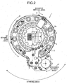
- FIG. 2 is a plan view of the analyzer shown in FIG. 1
- FIG. 3 is a partly sectional schematic view of a configuration of a stirring area
- FIG. 3A is a diagram indicating a status when a reaction vessel is transferred to the stirring area
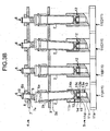
- FIG. 3B is a diagram indicating a stirring status of the specimen and the reagent
- FIG. 4 is a plan schematic view of a configuration of the stirring area, and is a diagram indicating a stirring status of the specimen and the reagent
- FIG. 5 is a block diagram of a configuration of the analyzer shown in FIG. 1 .
- the analyzer 1 includes a reagent setting area, a specimen setting area, a stirring area, and a B/F separation area. Further, a turntable 3 is rotatably provided to sequentially transfer a reaction vessel such as a cuvette (referred to below as "cuvette 2") to the areas (see FIG. 1 ).
- a reaction vessel such as a cuvette (referred to below as "cuvette 2"
- the reagent setting area and the specimen setting area are areas where the cuvette 2 is provided and where the specimen and the reagent containing magnetic carrier particles are consequently dispensed.
- the stirring area is an area where a reaction liquid consisting of the reagent and the specimen, which are dispensed into cuvette 2 in the reagent setting area and the specimen setting area, is stirred.
- the B/F separation area is an area where magnetic particles (i.e., magnetic carrier particles supporting the specimen) in the reaction liquid are gathered, cleaned, and dispersed with the use of a magnet, to carry out the B/F separation.
- the turntable 3 transfers the cuvette 2 sequentially to the reagent setting area, the specimen setting area, the stirring area, and the B/F separation area as described.
- the turntable 3 also has cuvette loading holes 3a in which the cuvettes 2 are loaded.
- the cuvette loading holes 3a are provided at regular intervals on a same circle, and a size of each cuvette loading hole 3a is a little larger than an outer diameter of the cuvette
- the cuvette 2 to be loaded in the cuvette loading hole 3a is a cylindrical reaction vessel having a bottom face and a side dace made of at least a transparent material. As shown in FIG. 3 , a flange part 2a extending downward from an upper opening is formed on an upper part of the cuvette 2. The flange part 2a is a little larger than the cuvette loading hole 3a formed on the turntable 3, so that the flange part 2a comes into contact with an edge of the cuvette loading hole 3a to prevent the cuvette 2 from falling out of the turntable 3.
- the stirring area is an area where the reaction liquid (mixed liquid of the specimen and the reagent) contained in the cuvette 2 is stirred by shaking the cuvette 2.
- the analyzer 1 according to the embodiment can stir, at the same time, reaction liquid contained in four of the cuvettes 2 loaded on the turntable 3.
- upper-part supporting units 4 and lower-part supporting units 5 are arranged corresponding to the four cuvettes 2 loaded on the turntable 3.
- the upper supporting unit 4 is fixed on a body of the analyzer, and does not interfere with the cuvette 2 loaded on the turntable 3 while the turntable 3 rotates, as shown in FIG. 3A .
- the upper-part supporting unit 4 closes and supports the upper opening of the cuvette 2, and includes four of supporting members 6 corresponding to the cuvettes, and an attachment member 7.
- attachment member 7 On the attachment member 7, four attachment holes 7a are provided, having a same pitch with the cuvette loading holes 3a provided on the turntable 3.
- Bushes 8 are attached to the attachment holes 7a.
- the supporting member 6 is attached to the bush 8 so as to move up and down. Since the bushes 8 are made of elastic material such as rubber for example, each supporting member 6 can be tilted.
- Each supporting member 6 includes a cuvette supporting part 6a and a shaft part 6b.
- Each cuvette supporting part 6a has a diameter larger than the upper opening of the cuvette 2, and has a rounded surface which becomes progressively wider upward, so as to securely close and support the cuvette 2.
- the shaft part 6b penetrates through the bush 8 to support the supporting member 6 in the bush 8, and is part extending upward from the cuvette supporting unit 6a.
- a compression coiled spring 9 is wound around the shaft unit 6b of each supporting member 6 to press each supporting member 6 downward. Further, an E-ring 10 is attached around the shaft part 6b of each supporting member 6 which penetrates through the bush 8. The E-ring 10 prevents the supporting member 6 from falling off by own weight of the supporting member 6 or the pressing force of the compression coiled spring 9.
- a lower-part supporting unit 5 can move up and down, and moves up without interfering with the cuvette 2 loaded on the turntable 3 being rotating, only when the turntable 3 is stopped, as shown in FIG. 3A .
- the cuvette 2 can be firmly held between the upper-part supporting member 4 and the lower-part supporting unit 5.
- the lower-part supporting unit 5 shakes the cuvette 2, which is firmly held, and includes four lower-part supporting members 11 corresponding to the cuvettes 2.
- Each lower-part supporting member 11 includes a gear unit 11a and a cuvette container 11b.
- the gear unit 11a is a part-where power is transmitted, and the cuvette container 11b is formed on a boss 11c extending upward from the gear unit 11a.
- the cuvette container 11b is a cylindrical concave part.
- a stirring member container hole 11d is formed on a bottom wall of the cuvette container 11b to be decentered from a rotation axis of the gear unit 11a.
- the stirring member container hole 11d contains a stirring member 12 for supporting a lower-part of the cuvette 2.
- the stirring member 12 includes a shaft 13 and a cuvette supporting unit 14.
- the shaft 13 includes a first shaft part 13a, a flange part 13b, and a second shaft part 13c.
- the first shaft part 13a is contained in the stirring member container hole 11d and has a cylindrical shape.
- the flange part 13b comes into contact with an outer edge of the stirring member container hole 11d to position the stirring member 12 in the direction of the shaft, and has a diameter larger than that of the first shaft part 13a.
- the second shaft part 13c supports an inner race of a bearing 15, and has a diameter smaller than that of the flange part 13b.
- the cuvette supporting unit 14 supports the lower-part of the cuvette 2, and supports an outer race of the bearing 15. Accordingly, the cuvette supporting unit 14 is rotatable around the shaft 13.
- the cuvette supporting unit 14 has a cylindrical shape, and a cone-shaped convex part 14a is formed on an upper surface of the cuvette supporting unit 14.
- the lower-part supporting members 11 are provided so that the gear units 11a are connected to each other in series. Specifically, starting from left to right in FIG. 3 , a first lower-part supporting member All, a second lower-part supporting member B11, a third lower-part supporting member C11, and a fourth lower-part supporting member D11 are provided, and the gear units 11a of the lower-part supporting members 11 sequentially engage with each other to transmit power. Specifically, when the first lower-part supporting member A11 is rotated in an anticlockwise direction in FIG. 4 , the second lower-part supporting member B11 rotates in a clockwise direction, the third lower-part supporting member C11 rotates in the anticlockwise direction, and the fourth lower-part supporting member D11 rotates in the clockwise direction. In other words, the adjacent lower-part supporting members 11 (i.e., the first lower-part supporting member All, the second lower-part supporting member B11, the third lower-part supporting member C11, and the fourth lower-part supporting member D11) rotate in opposite directions.
- the stirring members 12 contained in the lower-part supporting members 11 are arranged with a phase shifted from each other to cancel out vibration. Specifically, when a phase of the stirring member 12 contained in the first lower-part supporting member A11 is considered to be a reference (a decentering direction is indicated by arrow in FIG. 4 ), a phase of the stirring member 12 contained in the second lower-part supporting member B11 is shifted by 90 degrees in the anticlockwise direction, a phase of the stirring member 12 contained in the third lower-part supporting member C11 is shifted by 180 degrees, and a phase of the stirring member 12 contained in the fourth lower-part supporting member D11 is shifted by 90 degrees in the clockwise direction.
- an analysis unit 20 which analyzes the BF-separated reaction liquid by measuring photometric property of the same, is connected to a control unit 30, and is controlled by the control unit 30. Specifically, after a control signal from the control unit 30 makes the turntable 3 rotate by predetermined degrees, the lower-part supporting unit 5 is moved up and then the lower-part supporting unit 5 (the lower-part supporting member 11) is rotated, so that the reaction liquid is stirred. It should be noted that the analysis unit 20 is controlled by the control unit 20 to measure the photometric property of the reaction liquid contained in the cuvette 2 loaded on the turntable 3 every time the turntable 3 is rotated.
- the cuvette 2 is provided in the reagent setting area and the specimen setting area, the cuvette 2 is provided and the specimen and the reagent containing magnetic particles are dispensed.
- the lower-part supporting unit 5 starts to move upward.
- the cuvette 2 is contained in the cuvette container 11b, and the cuvette 2 comes into contact with the concave part 14a of the cuvette supporting unit 14 (the stirring member 12).
- the flange part 2a of the cuvette 2 moves upward away from the turntable 3, and the upper opening of the cuvette 2 is closed by the supporting member 6, whereby the cuvette 2 is held between the stirring member 12 and the supporting member 6. Since the stirring member 12 is contained in the stirring member container hole 11d, which is decentered from the rotation axis of the gear unit 11a of the lower-part supporting member 11, the cuvette 2 is tilted and firmly held.
- a driving source such as a motor rotates the first lower-part supporting member All in the counterclockwise direction
- the second lower-part supporting member B11 rotates in the clockwise direction
- the third lower-part supporting member C11 rotates in the counterclockwise direction
- the fourth lower-part supporting member D11 rotates in the clockwise direction as shown in FIG. 4 .
- the stirring member container hole 11d in which the stirring member 12 is contained is provided to be decentered from the rotation axis of the gear unit 11a, the lower-part of the cuvette 2, which is firmly held between the cuvette supporting unit 14 and the supporting member 6, is shaken following a track of a circle with a shaking center being set at the supporting member 6, whereby the reaction liquid is stirred. Further, the adjacent lower-parts of the cuvettes 2 are shaken in opposite directions following each track of circles.
- the stirring member container holes 11d which are provided on the first lower-part supporting member All, the second lower-part supporting member B11, the third lower-part supporting member C11, and the fourth lower-part supporting member D11, respectively, have phases shifted from each other, the rotation suppresses vibration in the stirring area.
- the lower-part supporting unit 5 starts to move downward. Then, after the upper opening of the cuvette 2 moves away from the cuvette supporting unit 6a, the flange part 2a of the cuvette 2 comes into contact with an edge of the cuvette loading hole 3a on the turntable 3. Then, when the lower-part supporting unit 5 moves downward to a sufficient degree and the cuvette 2 no longer interferes with the lower-part supporting unit 5, the turntable 3 becomes rotatable as shown in FIG. 3A .
- the magnetic particles i.e., magnetic carrier particles supporting the specimen
- the reaction liquid are gathered, cleaned, and dispersed with the use of the magnet, to carry out the B/F separation.
- the turntable 3 is rotated to transfer the cuvette 2 located in the reagent setting area and the specimen setting area to the stirring area, and the cuvette 2 located in the stirring area to the B/F separation area. Then, in each area, the procedure described above is repeated.
- gear unit 11a is formed in the lower-part supporting member 11 where the stirring member 12 to shake the cuvette 2 is arranged, and the gear units 11a formed in the adjacent lower-part supporting member 11 are provided to engage with each other, rotation of one of the lower-part supporting members 11 makes the adjacent lower-part supporting member 11 rotate in the opposite direction.
- a drive unit such as one motor can shake the lower-parts of the adjacent cuvette 2 in such a manner that the lower-parts follow each track of circles in opposite directions.
- stirring members 12 arranged in the adjacent lower-part supporting members 11 have phases shifted from each other to cancel out vibration of the adjacent cuvettes in the stirring area, vibration in the stirring area can be further suppressed.
- any configuration may be applied as long as the adjacent cuvettes 2 in the stirring area are shaken in opposite directions, and thus a pulley and a belt may be used, or a drive unit such as a motor may be provided for each lower-part supporting member 11.
- the present invention is not limited to the embodiment with the four cuvettes 2, and any number of cuvettes 2 may be shaken as long as the adjacent cuvettes 2 are shaken in the opposite directions.
- phase difference of the stirring member container holes 11d in which the stirring members 12 are contained is set to 90 degrees to suppress the vibration in the stirring area
- the phase difference is not limited to 90 degrees, and any phase difference may be used as long as the vibration in the stirring area is suppressed.
- the present invention may be applied to an analyzer using a microplate.
Landscapes
- Physics & Mathematics (AREA)
- Health & Medical Sciences (AREA)
- Life Sciences & Earth Sciences (AREA)
- Chemical & Material Sciences (AREA)
- Analytical Chemistry (AREA)
- Biochemistry (AREA)
- General Health & Medical Sciences (AREA)
- General Physics & Mathematics (AREA)
- Immunology (AREA)
- Pathology (AREA)
- Automatic Analysis And Handling Materials Therefor (AREA)
- Mixers With Rotating Receptacles And Mixers With Vibration Mechanisms (AREA)
Abstract
Description
- The present invention relates to an analyzer and particularly to an analyzer suitable for an immunological analysis and a genetic analysis.
- The analyzer used for an immunological measurement includes a reagent setting area where a reagent is set, a specimen setting area where a specimen is set, a stirring area where reaction liquid (i.e., mixed liquid of a specimen and a reagent) is stirred, and a B/F separation area where a B/F separation of reaction liquid is carried out. Further, to sequentially transfer a reaction vessel such as a cuvette (referred to below as "cuvette") to the areas, a turntable containing the cuvette is rotatably arranged in the analyzer.
- Further, the reaction liquid of the reagent and the specimen which are set in the reagent and specimen setting areas, respectively, is stirred by shaking the cuvette in the stirring area, and the reaction proceeds while the cuvette is transferred from the stirring area to the B/F separation area, i.e., while the turntable is rotating. Then, magnetic particles (magnetic carrier particle supporting the specimen) in the reaction liquid are gathered, cleaned, and dispersed with the use of a magnet in the B/F separation area, to carry out the B/F separation (e.g., see Patent Document 1)
- Patent Document 1: Japanese Patent Application Laid-Open No.
2003-83988 - When the cuvette is shaken in the stirring area, however, the cuvette hits the turntable, thereby causing vibration in the stirring area. Further, the vibration propagates through the turntable to the B/F separation area, resulting in vibration of the reaction liquid contained in the cuvette. This leads to inadequate B/F separation because the vibration prevents the magnetic particles from being gathered with the magnet. With the inadequate B/F separation, desired analysis data may not be acquired.
- The present invention is made in view of the foregoing, and an object of the present invention is to provide an analyzer which suppresses flowage of the reaction liquid in the B/F separation area by suppressing vibration in the stirring area, so that accurate analysis data can be acquired.
- To solve the abovementioned problems and to achieve an object of the present invention, the present invention is an analyzer including a stirring area where reaction liquid is stirred, a B/F separation area where a B/F separation of the reaction liquid is carried out, and a turntable which can sequentially transfer a reaction vessel containing the reaction liquid to the areas. The reaction vessels adjacent to each other in the stirring area are shaken in opposite directions.
- Further, the present invention includes lower-part supporting members each including a stirring member for shaking the reaction vessel, and gear units formed in the lower-part supporting members, respectively. The gear units are arranged so that the gear units in the adjacent lower-part supporting members engage with each other.
- Further, in the present invention, the stirring members in the lower-part supporting members are arranged to have phases shifted from each other so that the vibration of the adjacent reaction vessels in the stirring area is cancelled out.
- In the analyzer according to the present invention, the adjacent reaction vessels in the stirring area are shaken in the opposite directions, whereby vibration applied to the adjacent reaction vessels is cancelled out each other and vibration in the stirring area can be suppressed. As a result, flowage of reaction liquid in the B/F separation area can be suppressed, whereby accurate analysis data can be acquired.
- Further, the gear section is formed in the lower-part supporting member where the stirring member to shake the reaction vessel is arranged, and the gear sections formed in the adjacent lower-part supporting members are provided to engage with each other, whereby rotation of one lower-part supporting member can rotate an adjacent lower-part supporting member in the opposite direction. As a result, the adjacent reaction vessels can be shaken in the opposite directions with one drive unit.
- Further, to cancel out the vibration of the adjacent vessels in the stirring area, the adjacent stirring members, which are arranged in the lower-part supporting members, are arranged to have a phase shifted from each other, whereby vibration in the stirring area can be further suppressed.
-
-
FIG. 1 is a perspective view of an analyzer according to an embodiment of the present invention. -
FIG. 2 is a plan view of the analyzer shown inFIG. 1 . -
FIG. 3A is a partly sectional schematic view of a configuration of a stirring area, and is a diagram indicating a status when a reaction vessel is transferred to the stirring area. -
FIG. 3B is a partly sectional schematic view of the configuration of the stirring area, and is a diagram indicating a stirring status of a specimen and a reagent. -
FIG. 4 is a plan schematic view of a configuration of the stirring area, and is a diagram indicating a stirring status of the specimen and the reagent. -
FIG. 5 is a block diagram of a configuration of the analyzer shown inFIG. 5 . -
- 1
- Analyzer
- 2
- Cuvette
- 2a
- Flange
- 3
- Turntable
- 3a
- Cuvette loading hole
- 4
- Upper-part supporting unit
- 5
- Lower-part supporting unit
- 6
- Supporting member
- 6a
- Cuvette supporting part
- 6b
- Shaft part
- 7
- Attachment member
- 7a
- attachment hole
- 8
- Bush
- 9
- Compressed coiled spring
- 10
- E-ring
- 11
- Lower-part supporting member
- 11a
- Gear unit
- 11b
- Cuvette container
- 11c
- Boss
- 11d
- Stirring member container hole
- 12
- Stirring member
- 13
- Shaft
- 13a
- First shaft part
- 13b
- Flange part
- 13c
- Second shaft part
- 14
- Cuvette supporting unit
- 14a
- Concave part
- 15
- Bearing
- 20
- Analysis unit
- 30
- Control unit
- A11
- First lower-part supporting member
- B11
- Second lower-part supporting member
- C11
- Third lower-part supporting member
- D11
- Fourth lower-part supporting member
- Exemplary embodiments of an analyzer according to the present invention are described in detail below with reference to drawings. The present invention, however, is not limited to the embodiments.
-
FIG. 1 is a perspective view of an analyzer according to an embodiment of the present invention,FIG. 2 is a plan view of the analyzer shown inFIG. 1 ,FIG. 3 is a partly sectional schematic view of a configuration of a stirring area,FIG. 3A is a diagram indicating a status when a reaction vessel is transferred to the stirring area,FIG. 3B is a diagram indicating a stirring status of the specimen and the reagent,FIG. 4 is a plan schematic view of a configuration of the stirring area, and is a diagram indicating a stirring status of the specimen and the reagent, andFIG. 5 is a block diagram of a configuration of the analyzer shown inFIG. 1 . - The analyzer 1 according to the embodiment of the present invention includes a reagent setting area, a specimen setting area, a stirring area, and a B/F separation area. Further, a
turntable 3 is rotatably provided to sequentially transfer a reaction vessel such as a cuvette (referred to below as "cuvette 2") to the areas (seeFIG. 1 ). - The reagent setting area and the specimen setting area are areas where the
cuvette 2 is provided and where the specimen and the reagent containing magnetic carrier particles are consequently dispensed. The stirring area is an area where a reaction liquid consisting of the reagent and the specimen, which are dispensed intocuvette 2 in the reagent setting area and the specimen setting area, is stirred. Further, the B/F separation area is an area where magnetic particles (i.e., magnetic carrier particles supporting the specimen) in the reaction liquid are gathered, cleaned, and dispersed with the use of a magnet, to carry out the B/F separation. - The
turntable 3 transfers thecuvette 2 sequentially to the reagent setting area, the specimen setting area, the stirring area, and the B/F separation area as described. Theturntable 3 also hascuvette loading holes 3a in which thecuvettes 2 are loaded. Thecuvette loading holes 3a are provided at regular intervals on a same circle, and a size of eachcuvette loading hole 3a is a little larger than an outer diameter of the cuvette - The
cuvette 2 to be loaded in thecuvette loading hole 3a is a cylindrical reaction vessel having a bottom face and a side dace made of at least a transparent material. As shown inFIG. 3 , aflange part 2a extending downward from an upper opening is formed on an upper part of thecuvette 2. Theflange part 2a is a little larger than thecuvette loading hole 3a formed on theturntable 3, so that theflange part 2a comes into contact with an edge of thecuvette loading hole 3a to prevent thecuvette 2 from falling out of theturntable 3. - The stirring area is an area where the reaction liquid (mixed liquid of the specimen and the reagent) contained in the
cuvette 2 is stirred by shaking thecuvette 2. The analyzer 1 according to the embodiment can stir, at the same time, reaction liquid contained in four of thecuvettes 2 loaded on theturntable 3. - In the stirring area, upper-
part supporting units 4 and lower-part supporting units 5 are arranged corresponding to the fourcuvettes 2 loaded on theturntable 3. The upper supportingunit 4 is fixed on a body of the analyzer, and does not interfere with thecuvette 2 loaded on theturntable 3 while theturntable 3 rotates, as shown inFIG. 3A . The upper-part supporting unit 4 closes and supports the upper opening of thecuvette 2, and includes four of supportingmembers 6 corresponding to the cuvettes, and anattachment member 7. - On the
attachment member 7, fourattachment holes 7a are provided, having a same pitch with thecuvette loading holes 3a provided on theturntable 3. Bushes 8 are attached to theattachment holes 7a. The supportingmember 6 is attached to the bush 8 so as to move up and down. Since the bushes 8 are made of elastic material such as rubber for example, each supportingmember 6 can be tilted. - Each supporting
member 6 includes acuvette supporting part 6a and ashaft part 6b. Eachcuvette supporting part 6a has a diameter larger than the upper opening of thecuvette 2, and has a rounded surface which becomes progressively wider upward, so as to securely close and support thecuvette 2. Theshaft part 6b penetrates through the bush 8 to support the supportingmember 6 in the bush 8, and is part extending upward from thecuvette supporting unit 6a. - A compression coiled
spring 9 is wound around theshaft unit 6b of each supportingmember 6 to press each supportingmember 6 downward. Further, an E-ring 10 is attached around theshaft part 6b of each supportingmember 6 which penetrates through the bush 8. The E-ring 10 prevents the supportingmember 6 from falling off by own weight of the supportingmember 6 or the pressing force of the compression coiledspring 9. - A lower-
part supporting unit 5 can move up and down, and moves up without interfering with thecuvette 2 loaded on theturntable 3 being rotating, only when theturntable 3 is stopped, as shown inFIG. 3A . Thecuvette 2 can be firmly held between the upper-part supporting member 4 and the lower-part supporting unit 5. The lower-part supporting unit 5 shakes thecuvette 2, which is firmly held, and includes four lower-part supporting members 11 corresponding to thecuvettes 2. Each lower-part supporting member 11 includes agear unit 11a and acuvette container 11b. - The
gear unit 11a is a part-where power is transmitted, and thecuvette container 11b is formed on aboss 11c extending upward from thegear unit 11a. Thecuvette container 11b is a cylindrical concave part. A stirringmember container hole 11d is formed on a bottom wall of thecuvette container 11b to be decentered from a rotation axis of thegear unit 11a. - The stirring
member container hole 11d contains a stirringmember 12 for supporting a lower-part of thecuvette 2. The stirringmember 12 includes ashaft 13 and acuvette supporting unit 14. Theshaft 13 includes afirst shaft part 13a, aflange part 13b, and asecond shaft part 13c. Thefirst shaft part 13a is contained in the stirringmember container hole 11d and has a cylindrical shape. Theflange part 13b comes into contact with an outer edge of the stirringmember container hole 11d to position the stirringmember 12 in the direction of the shaft, and has a diameter larger than that of thefirst shaft part 13a. Thesecond shaft part 13c supports an inner race of abearing 15, and has a diameter smaller than that of theflange part 13b. Thecuvette supporting unit 14 supports the lower-part of thecuvette 2, and supports an outer race of thebearing 15. Accordingly, thecuvette supporting unit 14 is rotatable around theshaft 13. Thecuvette supporting unit 14 has a cylindrical shape, and a cone-shapedconvex part 14a is formed on an upper surface of thecuvette supporting unit 14. - The lower-
part supporting members 11 are provided so that thegear units 11a are connected to each other in series. Specifically, starting from left to right inFIG. 3 , a first lower-part supporting member All, a second lower-part supporting member B11, a third lower-part supporting member C11, and a fourth lower-part supporting member D11 are provided, and thegear units 11a of the lower-part supporting members 11 sequentially engage with each other to transmit power. Specifically, when the first lower-part supporting member A11 is rotated in an anticlockwise direction inFIG. 4 , the second lower-part supporting member B11 rotates in a clockwise direction, the third lower-part supporting member C11 rotates in the anticlockwise direction, and the fourth lower-part supporting member D11 rotates in the clockwise direction. In other words, the adjacent lower-part supporting members 11 (i.e., the first lower-part supporting member All, the second lower-part supporting member B11, the third lower-part supporting member C11, and the fourth lower-part supporting member D11) rotate in opposite directions. - The stirring
members 12 contained in the lower-part supporting members 11 are arranged with a phase shifted from each other to cancel out vibration. Specifically, when a phase of the stirringmember 12 contained in the first lower-part supporting member A11 is considered to be a reference (a decentering direction is indicated by arrow inFIG. 4 ), a phase of the stirringmember 12 contained in the second lower-part supporting member B11 is shifted by 90 degrees in the anticlockwise direction, a phase of the stirringmember 12 contained in the third lower-part supporting member C11 is shifted by 180 degrees, and a phase of the stirringmember 12 contained in the fourth lower-part supporting member D11 is shifted by 90 degrees in the clockwise direction. - As shown in
FIG. 5 , besides theturntable 3 and the lower-part supporting unit 5 described above, ananalysis unit 20, which analyzes the BF-separated reaction liquid by measuring photometric property of the same, is connected to acontrol unit 30, and is controlled by thecontrol unit 30. Specifically, after a control signal from thecontrol unit 30 makes theturntable 3 rotate by predetermined degrees, the lower-part supporting unit 5 is moved up and then the lower-part supporting unit 5 (the lower-part supporting member 11) is rotated, so that the reaction liquid is stirred. It should be noted that theanalysis unit 20 is controlled by thecontrol unit 20 to measure the photometric property of the reaction liquid contained in thecuvette 2 loaded on theturntable 3 every time theturntable 3 is rotated. - In the analyzer 1 described above, in the reagent setting area and the specimen setting area, the
cuvette 2 is provided and the specimen and the reagent containing magnetic particles are dispensed. - On the other hand, in the stirring area, as shown in
FIG. 3B , firstly the lower-part supporting unit 5 starts to move upward. As the lower-part supporting unit 5 starts to move upward, thecuvette 2 is contained in thecuvette container 11b, and thecuvette 2 comes into contact with theconcave part 14a of the cuvette supporting unit 14 (the stirring member 12). When the lower-part supporting unit 5 further moves upward, theflange part 2a of thecuvette 2 moves upward away from theturntable 3, and the upper opening of thecuvette 2 is closed by the supportingmember 6, whereby thecuvette 2 is held between the stirringmember 12 and the supportingmember 6. Since the stirringmember 12 is contained in the stirringmember container hole 11d, which is decentered from the rotation axis of thegear unit 11a of the lower-part supporting member 11, thecuvette 2 is tilted and firmly held. - Next, when a driving source (not shown) such as a motor rotates the first lower-part supporting member All in the counterclockwise direction, the second lower-part supporting member B11 rotates in the clockwise direction, the third lower-part supporting member C11 rotates in the counterclockwise direction, and the fourth lower-part supporting member D11 rotates in the clockwise direction as shown in
FIG. 4 . - In the description above, since the stirring
member container hole 11d in which the stirringmember 12 is contained is provided to be decentered from the rotation axis of thegear unit 11a, the lower-part of thecuvette 2, which is firmly held between thecuvette supporting unit 14 and the supportingmember 6, is shaken following a track of a circle with a shaking center being set at the supportingmember 6, whereby the reaction liquid is stirred. Further, the adjacent lower-parts of thecuvettes 2 are shaken in opposite directions following each track of circles. Since the stirringmember container holes 11d, which are provided on the first lower-part supporting member All, the second lower-part supporting member B11, the third lower-part supporting member C11, and the fourth lower-part supporting member D11, respectively, have phases shifted from each other, the rotation suppresses vibration in the stirring area. - When the stirring of the reaction liquid is completed, the lower-
part supporting unit 5 starts to move downward. Then, after the upper opening of thecuvette 2 moves away from thecuvette supporting unit 6a, theflange part 2a of thecuvette 2 comes into contact with an edge of thecuvette loading hole 3a on theturntable 3. Then, when the lower-part supporting unit 5 moves downward to a sufficient degree and thecuvette 2 no longer interferes with the lower-part supporting unit 5, theturntable 3 becomes rotatable as shown inFIG. 3A . - On the other hand, in the B/F separation area, the magnetic particles (i.e., magnetic carrier particles supporting the specimen) in the reaction liquid are gathered, cleaned, and dispersed with the use of the magnet, to carry out the B/F separation.
- When each of the operations described above in the reagent setting area, the specimen setting area, the stirring area, the B/F separation area, are completed, the
turntable 3 is rotated to transfer thecuvette 2 located in the reagent setting area and the specimen setting area to the stirring area, and thecuvette 2 located in the stirring area to the B/F separation area. Then, in each area, the procedure described above is repeated. - In the analyzer described above, since the lower-parts of the
adjacent cuvettes 2 in the stirring area are shaken in opposite directions following each track of circles with the shaking center being set at the supportingmember 6, vibration applied to the adjacent cuvettes is cancelled out, whereby vibration in the stirring area can be suppressed. As a result, flowage of the reaction liquid in the B/F separation area can be suppressed, and accurate analysis data can be acquired. - Further, since the
gear unit 11a is formed in the lower-part supporting member 11 where the stirringmember 12 to shake thecuvette 2 is arranged, and thegear units 11a formed in the adjacent lower-part supporting member 11 are provided to engage with each other, rotation of one of the lower-part supporting members 11 makes the adjacent lower-part supporting member 11 rotate in the opposite direction. As a result, a drive unit such as one motor can shake the lower-parts of theadjacent cuvette 2 in such a manner that the lower-parts follow each track of circles in opposite directions. - Further, since the stirring
members 12 arranged in the adjacent lower-part supporting members 11 have phases shifted from each other to cancel out vibration of the adjacent cuvettes in the stirring area, vibration in the stirring area can be further suppressed. - Although the lower-
part supporting members 11 are provided to make thegear units 11a engage with each other in series in the analyzer according to the embodiment describe above, any configuration may be applied as long as theadjacent cuvettes 2 in the stirring area are shaken in opposite directions, and thus a pulley and a belt may be used, or a drive unit such as a motor may be provided for each lower-part supporting member 11. - Further, although it is described that four
cuvettes 2 in the stirring area are shaken to stir the reaction liquid, the present invention is not limited to the embodiment with the fourcuvettes 2, and any number ofcuvettes 2 may be shaken as long as theadjacent cuvettes 2 are shaken in the opposite directions. - Further, although the phase difference of the stirring
member container holes 11d in which the stirringmembers 12 are contained is set to 90 degrees to suppress the vibration in the stirring area, the phase difference is not limited to 90 degrees, and any phase difference may be used as long as the vibration in the stirring area is suppressed. - Further, not limited to the analyzer using the
cuvette 2, the present invention may be applied to an analyzer using a microplate.
Claims (3)
- An analyzer comprising
a stirring area where reaction liquid is stirred;
a B/F separation area where a B/F separation of the reaction liquid is carried out; and
a turntable which can sequentially transfer a reaction vessel containing the reaction liquid to the areas, wherein
the reaction vessels adjacent to each other in the stirring area are shaken in opposite directions. - The analyzer according to claim 1, further comprising:lower-part supporting members each including a stirring member for shaking the reaction vessel; andgear units formed in the lower-part supporting members, respectively, whereinthe gear units are arranged so that the gear units in the adjacent lower-part supporting members engage with each other.
- The analyzer according to claim 1 or 2, wherein
the stirring members in the adjacent lower-part supporting members are arranged to have phases shifted from each other so that the vibration of the adjacent reaction vessels in the stirring area is cancelled out.
Applications Claiming Priority (2)
| Application Number | Priority Date | Filing Date | Title |
|---|---|---|---|
| JP2006141666 | 2006-05-22 | ||
| PCT/JP2007/060055 WO2007135921A1 (en) | 2006-05-22 | 2007-05-16 | Analytical instrument |
Publications (1)
| Publication Number | Publication Date |
|---|---|
| EP2023148A1 true EP2023148A1 (en) | 2009-02-11 |
Family
ID=38723235
Family Applications (1)
| Application Number | Title | Priority Date | Filing Date |
|---|---|---|---|
| EP07743490A Withdrawn EP2023148A1 (en) | 2006-05-22 | 2007-05-16 | Analytical instrument |
Country Status (5)
| Country | Link |
|---|---|
| US (1) | US20090191094A1 (en) |
| EP (1) | EP2023148A1 (en) |
| JP (1) | JPWO2007135921A1 (en) |
| CN (1) | CN101449169A (en) |
| WO (1) | WO2007135921A1 (en) |
Families Citing this family (8)
| Publication number | Priority date | Publication date | Assignee | Title |
|---|---|---|---|---|
| CN101147071B (en) * | 2005-04-01 | 2011-12-14 | 三菱化学美迪恩斯株式会社 | Composite automatic analysis device, automatic analysis method and reaction cup for biological samples |
| JP5336889B2 (en) * | 2009-03-09 | 2013-11-06 | ベックマン コールター, インコーポレイテッド | Reaction vessel holder and analyzer |
| JP5478360B2 (en) * | 2010-05-20 | 2014-04-23 | 株式会社日立ハイテクノロジーズ | Automatic analyzer |
| JP5613522B2 (en) * | 2010-10-12 | 2014-10-22 | シスメックス株式会社 | Sample analyzer |
| FR3000803B1 (en) * | 2013-01-04 | 2018-05-25 | Immunodiagnostic Systems France | ANALYSIS ASSEMBLY FOR ANALYSIS APPARATUS |
| CN104297039B (en) * | 2014-09-25 | 2017-01-11 | 深圳市奥特库贝科技有限公司 | Novel magnetic separation mechanism |
| CN105445481B (en) * | 2015-12-15 | 2017-12-12 | 苏州长光华医生物医学工程有限公司 | A kind of reactant oscillating uniform device |
| WO2020037670A1 (en) * | 2018-08-24 | 2020-02-27 | 深圳迈瑞生物医疗电子股份有限公司 | Blood sample analyzer and blood sample homogenization method |
Family Cites Families (4)
| Publication number | Priority date | Publication date | Assignee | Title |
|---|---|---|---|---|
| JPH03296429A (en) * | 1990-04-13 | 1991-12-27 | Internatl Reagents Corp | Mixing apparatus |
| JPH07260794A (en) * | 1994-03-23 | 1995-10-13 | Omron Corp | Stirring mechanism of sample preparation device |
| JP2002196006A (en) * | 2000-12-27 | 2002-07-10 | Olympus Optical Co Ltd | Automatic analyzer |
| JP5193408B2 (en) * | 2001-09-13 | 2013-05-08 | ベックマン コールター, インコーポレイテッド | Automatic analyzer |
-
2007
- 2007-05-16 CN CNA2007800185612A patent/CN101449169A/en active Pending
- 2007-05-16 EP EP07743490A patent/EP2023148A1/en not_active Withdrawn
- 2007-05-16 JP JP2008516627A patent/JPWO2007135921A1/en not_active Withdrawn
- 2007-05-16 WO PCT/JP2007/060055 patent/WO2007135921A1/en not_active Ceased
-
2008
- 2008-11-21 US US12/275,687 patent/US20090191094A1/en not_active Abandoned
Non-Patent Citations (1)
| Title |
|---|
| See references of WO2007135921A1 * |
Also Published As
| Publication number | Publication date |
|---|---|
| JPWO2007135921A1 (en) | 2009-10-01 |
| CN101449169A (en) | 2009-06-03 |
| WO2007135921A1 (en) | 2007-11-29 |
| US20090191094A1 (en) | 2009-07-30 |
Similar Documents
| Publication | Publication Date | Title |
|---|---|---|
| US20090191094A1 (en) | Analyzer | |
| CA2032696C (en) | Selective component agitation apparatus and method | |
| US11291965B2 (en) | Evaporation-controlling container inserts | |
| US8017094B2 (en) | Rack for analyzer and analyzer comprising such a rack | |
| US20020132353A1 (en) | Turntable type liquid reagent stirring apparatus and turntable type liquid reagent stirring/fractionally pouring apparatus using said stirring apparatus | |
| NL8300092A (en) | Apparatus for rotating reaction holders in an inclined arrangement. | |
| CN101162236A (en) | Analyzer, reagent container, and reagent aspirating method | |
| JP7322195B2 (en) | automatic analyzer | |
| JP2008298692A (en) | Sample stirring device and sample analyzer | |
| EP0525577A2 (en) | Carrier device | |
| CN108369237A (en) | Automatic analysing apparatus | |
| JP4653771B2 (en) | Reagent container transport device | |
| JP2008096223A (en) | Analyzer | |
| JPH0725217Y2 (en) | Stirrer | |
| WO2026048227A1 (en) | Automatic analyzer and container storage | |
| JP4713401B2 (en) | Stirring device and automatic analyzer using the same | |
| JPS6134855B2 (en) |
Legal Events
| Date | Code | Title | Description |
|---|---|---|---|
| PUAI | Public reference made under article 153(3) epc to a published international application that has entered the european phase |
Free format text: ORIGINAL CODE: 0009012 |
|
| 17P | Request for examination filed |
Effective date: 20081127 |
|
| AK | Designated contracting states |
Kind code of ref document: A1 Designated state(s): AT BE BG CH CY CZ DE DK EE ES FI FR GB GR HU IE IS IT LI LT LU LV MC MT NL PL PT RO SE SI SK TR |
|
| AX | Request for extension of the european patent |
Extension state: AL BA HR MK RS |
|
| DAX | Request for extension of the european patent (deleted) | ||
| RBV | Designated contracting states (corrected) |
Designated state(s): DE FR GB |
|
| RAP1 | Party data changed (applicant data changed or rights of an application transferred) |
Owner name: BECKMAN COULTER, INC. |
|
| RAP1 | Party data changed (applicant data changed or rights of an application transferred) |
Owner name: BECKMAN COULTER, INC. |
|
| STAA | Information on the status of an ep patent application or granted ep patent |
Free format text: STATUS: THE APPLICATION IS DEEMED TO BE WITHDRAWN |
|
| 18D | Application deemed to be withdrawn |
Effective date: 20121201 |