EP2023012A1 - Screw device and method of producing same - Google Patents
Screw device and method of producing same Download PDFInfo
- Publication number
- EP2023012A1 EP2023012A1 EP07742691A EP07742691A EP2023012A1 EP 2023012 A1 EP2023012 A1 EP 2023012A1 EP 07742691 A EP07742691 A EP 07742691A EP 07742691 A EP07742691 A EP 07742691A EP 2023012 A1 EP2023012 A1 EP 2023012A1
- Authority
- EP
- European Patent Office
- Prior art keywords
- rolling
- nut
- groove
- loaded
- deflector
- Prior art date
- Legal status (The legal status is an assumption and is not a legal conclusion. Google has not performed a legal analysis and makes no representation as to the accuracy of the status listed.)
- Granted
Links
Images











Classifications
-
- F—MECHANICAL ENGINEERING; LIGHTING; HEATING; WEAPONS; BLASTING
- F16—ENGINEERING ELEMENTS AND UNITS; GENERAL MEASURES FOR PRODUCING AND MAINTAINING EFFECTIVE FUNCTIONING OF MACHINES OR INSTALLATIONS; THERMAL INSULATION IN GENERAL
- F16H—GEARING
- F16H25/00—Gearings comprising primarily only cams, cam-followers and screw-and-nut mechanisms
- F16H25/18—Gearings comprising primarily only cams, cam-followers and screw-and-nut mechanisms for conveying or interconverting oscillating or reciprocating motions
- F16H25/20—Screw mechanisms
- F16H25/22—Screw mechanisms with balls, rollers, or similar members between the co-operating parts; Elements essential to the use of such members
- F16H25/2204—Screw mechanisms with balls, rollers, or similar members between the co-operating parts; Elements essential to the use of such members with balls
- F16H25/2214—Screw mechanisms with balls, rollers, or similar members between the co-operating parts; Elements essential to the use of such members with balls with elements for guiding the circulating balls
- F16H25/2223—Cross over deflectors between adjacent thread turns, e.g. S-form deflectors connecting neighbouring threads
-
- B—PERFORMING OPERATIONS; TRANSPORTING
- B29—WORKING OF PLASTICS; WORKING OF SUBSTANCES IN A PLASTIC STATE IN GENERAL
- B29C—SHAPING OR JOINING OF PLASTICS; SHAPING OF MATERIAL IN A PLASTIC STATE, NOT OTHERWISE PROVIDED FOR; AFTER-TREATMENT OF THE SHAPED PRODUCTS, e.g. REPAIRING
- B29C45/00—Injection moulding, i.e. forcing the required volume of moulding material through a nozzle into a closed mould; Apparatus therefor
- B29C45/17—Component parts, details or accessories; Auxiliary operations
- B29C45/26—Moulds
- B29C45/2618—Moulds having screw-threaded mould walls
-
- F—MECHANICAL ENGINEERING; LIGHTING; HEATING; WEAPONS; BLASTING
- F16—ENGINEERING ELEMENTS AND UNITS; GENERAL MEASURES FOR PRODUCING AND MAINTAINING EFFECTIVE FUNCTIONING OF MACHINES OR INSTALLATIONS; THERMAL INSULATION IN GENERAL
- F16H—GEARING
- F16H25/00—Gearings comprising primarily only cams, cam-followers and screw-and-nut mechanisms
- F16H25/18—Gearings comprising primarily only cams, cam-followers and screw-and-nut mechanisms for conveying or interconverting oscillating or reciprocating motions
- F16H25/20—Screw mechanisms
- F16H25/22—Screw mechanisms with balls, rollers, or similar members between the co-operating parts; Elements essential to the use of such members
- F16H25/2204—Screw mechanisms with balls, rollers, or similar members between the co-operating parts; Elements essential to the use of such members with balls
- F16H25/2214—Screw mechanisms with balls, rollers, or similar members between the co-operating parts; Elements essential to the use of such members with balls with elements for guiding the circulating balls
-
- B—PERFORMING OPERATIONS; TRANSPORTING
- B29—WORKING OF PLASTICS; WORKING OF SUBSTANCES IN A PLASTIC STATE IN GENERAL
- B29L—INDEXING SCHEME ASSOCIATED WITH SUBCLASS B29C, RELATING TO PARTICULAR ARTICLES
- B29L2031/00—Other particular articles
- B29L2031/04—Bearings
-
- F—MECHANICAL ENGINEERING; LIGHTING; HEATING; WEAPONS; BLASTING
- F16—ENGINEERING ELEMENTS AND UNITS; GENERAL MEASURES FOR PRODUCING AND MAINTAINING EFFECTIVE FUNCTIONING OF MACHINES OR INSTALLATIONS; THERMAL INSULATION IN GENERAL
- F16H—GEARING
- F16H25/00—Gearings comprising primarily only cams, cam-followers and screw-and-nut mechanisms
- F16H25/18—Gearings comprising primarily only cams, cam-followers and screw-and-nut mechanisms for conveying or interconverting oscillating or reciprocating motions
- F16H25/20—Screw mechanisms
- F16H25/24—Elements essential to such mechanisms, e.g. screws, nuts
- F16H2025/2481—Special features for facilitating the manufacturing of spindles, nuts, or sleeves of screw devices
-
- Y—GENERAL TAGGING OF NEW TECHNOLOGICAL DEVELOPMENTS; GENERAL TAGGING OF CROSS-SECTIONAL TECHNOLOGIES SPANNING OVER SEVERAL SECTIONS OF THE IPC; TECHNICAL SUBJECTS COVERED BY FORMER USPC CROSS-REFERENCE ART COLLECTIONS [XRACs] AND DIGESTS
- Y10—TECHNICAL SUBJECTS COVERED BY FORMER USPC
- Y10T—TECHNICAL SUBJECTS COVERED BY FORMER US CLASSIFICATION
- Y10T29/00—Metal working
- Y10T29/49—Method of mechanical manufacture
- Y10T29/49636—Process for making bearing or component thereof
- Y10T29/49643—Rotary bearing
- Y10T29/49679—Anti-friction bearing or component thereof
- Y10T29/49691—Cage making
-
- Y—GENERAL TAGGING OF NEW TECHNOLOGICAL DEVELOPMENTS; GENERAL TAGGING OF CROSS-SECTIONAL TECHNOLOGIES SPANNING OVER SEVERAL SECTIONS OF THE IPC; TECHNICAL SUBJECTS COVERED BY FORMER USPC CROSS-REFERENCE ART COLLECTIONS [XRACs] AND DIGESTS
- Y10—TECHNICAL SUBJECTS COVERED BY FORMER USPC
- Y10T—TECHNICAL SUBJECTS COVERED BY FORMER US CLASSIFICATION
- Y10T74/00—Machine element or mechanism
- Y10T74/19—Gearing
- Y10T74/19642—Directly cooperating gears
- Y10T74/19698—Spiral
- Y10T74/19702—Screw and nut
- Y10T74/19744—Rolling element engaging thread
- Y10T74/19749—Recirculating rolling elements
- Y10T74/19767—Return path geometry
- Y10T74/19772—Rolling element deflector
Definitions
- Each ball 3 moves from the loaded ball rolling groove 2a of the nut 2 to the ball return path of the return pipe 4, and vice versa.
- the ball 3 is prevented from moving smoothly. Accordingly, as shown in Fig. 31 , in order to eliminate the elevation change at the joint 6 of the ball return path 5 and the loaded ball rolling groove 2a, a connecting part 7 of the loaded ball rolling groove 2a to the ball return path 5 is subjected to chamfering.
- the cross section of the loaded ball rolling groove 2a is shaped like Gothic arch composed of two arcs so that each of the balls is in contact with the loaded ball rolling groove 2a at two points.
- the cross section of the ball return path 5 is shaped like a single arc.
- the connecting part 7 is also chamfered so that the cross section of the loaded ball rolling groove 2a is changed gradually to conform to the cross section of the ball return path 5 at the joint 6 thereof.
- the wing type deflector 82 which can be inserted into a nut 81 without any adhesive agent, as shown in Fig. 33 (see the patent document 2).
- the wing type deflector 82 has a deflector main body 82a having a return groove 82c formed therein and a wing part 82b which juts from a side surface of the deflector main body 82a and fits into the loaded ball rolling groove 81a of the nut 81.
- balls 85 arranged so that the deflector 82 is prevented from falling into the screw shaft 84 side.
- the present invention has an object to provide a screw device capable of preventing occurrence of any elevation change at a joint between the loaded ball rolling groove of the nut and the ball return path of the circulation member and a method of manufacturing the same.
- loads from the balls 75 may be repeatedly put on the deflector 73, and coolant, cutting oil and the like may be splashed on the deflector 73, resulting in reduction of strength of the adhesive agent.
- the outer shape of the deflector 73 is slightly smaller than the deflector hole 72.
- the deflector 73 is sometimes misaligned. This may causes a space or elevation change at the joint 78 of the loaded ball rolling groove 71a of the nut 71 and the return groove 73a of the deflector 73.
- the deflector 82 has swung, or being inclined, from the state indicated by the slid line in the figure to the state indicated by the broken line in the figure, there occur a space, elevation change and the like at the joint 86 of the return groove 82c of the deflector 82 and the loaded ball rolling groove 81a of the nut 81.
- the elevation change and space at the joint may prevent smooth movement of the balls.
- the balls 85 interposed between the screw shaft 84 and the return groove 82c of the deflector 82 act to prevent the deflector 82 from falling toward the screw shaft 84.
- the deflector 82 slightly falls toward the screw shaft 84 side.
- clearance is formed at the end part of the return groove 82c so that when the deflector 82 falls toward the screw shaft 84, the balls 85 do not bump into the end part of the return groove 82c.
- the clearance is formed at the end part of the return groove 82c, when the deflector 82 is raised, the clearance formed for preventing the elevation change may cause another elevation change.
- the present invention has an object to provide a screw device capable of preventing occurrence of an elevation change at a joint between the loaded ball rolling groove of the nut and the ball return groove of the deflector and a method of manufacturing the same.
- the invention of claim 1 is a screw device comprising: a screw shaft having an outer peripheral surface with a rolling-element rolling groove spirally formed thereon; a nut having an inner peripheral surface with a loaded rolling-element rolling groove spirally formed thereon facing the rolling-element rolling groove of the screw shaft; a circulation member having a rolling-element return path connecting one end of the loaded rolling-element rolling groove of the nut with an opposite end thereof; and a plurality of rolling elements arranged in the rolling-element return path of the circulation member and a loaded rolling-element rolling path between the rolling-element rolling groove of the screw shaft and the loaded rolling-element rolling groove of the nut, the rolling elements rolling in the loaded rolling-element rolling path, being scooped up at an end part of the circulation member and returned into the loaded rolling-element rolling path by an opposite end part of the circulation member, the end part of the circulation member having an periphery including a rolling groove connecting part which is positioned to a
- the invention of claim 2 is characterized in that, in the screw device of claim 1, the scooping part of the end part of the circulation member is made of resin and formed integral with the rolling groove connecting part.
- the invention of claim 3 is characterized in that, in the screw device of claim 1 or 2, the nut has a side surface having a through hole formed therein which reaches the loaded rolling-element rolling groove of the nut, and at least the rolling groove connecting part of the end part of the circulation member is formed integral with an inner peripheral surface of the through hole.
- the invention of claim 4 is characterized in that, in the screw device of claim 3, a space is formed between the inner peripheral surface of the through hole and an outer peripheral surface of the scooping part of the end part so that a die is inserted into the space.
- the invention of claim 5 is characterized in that, in the screw device of claim 3 or 4, each of the end parts juts from the through hole, the circulation member has a connecting part which connects the end parts of the circulation member each jutting from the through hole, and the connecting part has a connecting return path formed therein connecting rolling-element return paths of the end parts.
- the invention of claim 6 is characterized in that, in the screw device of any one of claims 1 to 5, a spacer is interposed to prevent contact between the rolling elements.
- the invention of claim 7 is characterized in that, in the screw device of claim 1 or 2, the circulation member is a deflector mounted on the nut for returning the rolling elements on the loaded rolling-element rolling path one turn back to the rolling element rolling groove, the nut has a deflector hole formed therein which reaches the loaded rolling-element rolling groove of the nut, and at least the rolling groove connecting part of the end part of the deflector is formed integral with an inner surface of the deflector hole.
- the invention of claim 8 is a method of manufacturing a screw device having: a screw shaft having an outer peripheral surface with a rolling-element rolling groove spirally formed thereon; a nut having an inner peripheral surface with a loaded rolling-element rolling groove spirally formed thereon facing the rolling-element rolling groove of the screw shaft; a circulation member having a rolling-element return path connecting one end of the loaded rolling-element rolling groove of the nut with an opposite end thereof; and a plurality of rolling elements arranged in the rolling-element return path of the circulation member and a loaded rolling-element rolling path between the rolling-element rolling groove of the screw shaft and the loaded rolling-element rolling groove of the nut, the rolling elements rolling in the loaded rolling-element rolling path, being scooped up at an end part of the circulation member and returned into the loaded rolling-element rolling path by an opposite end part of the circulation member, the end part of the circulation member having an periphery including a rolling groove connecting part which is positioned to a side of the loaded rolling-element
- the invention of claim 9 is characterized in that, in the method of claim 8, the scooping part of the end part of the circulation member is formed integral with the rolling groove connecting part with resin.
- the invention of claim 10 is characterized in that, in the method of claim 8 or 9, a through hole is formed in a side surface of the nut so as to reach the loaded rolling-element rolling groove of the inner peripheral surface of the nut, and at least the rolling groove connecting part of the end part of the circulation member is formed integral with an inner surface of the through hole.
- the invention of claim 11 is characterized in that, in the method of any one of claims 8 to 10, the die includes a nut inside die which is placed inside the nut to form the end part of the circulation member jutting inside the nut.
- the invention of claim 12 is characterized in that, in the method of any one of claims 8 to 11, the die includes a pin shaped die which is inserted in a through hole formed in a side surface of the nut to form the rolling-element return path of the end part of the circulation member.
- the invention of claim 13 is characterized in that, in the method of any one of claims 8 to 12, the die includes a cross-sectionally arc shaped die which is inserted in a through hole formed in a side surface of the nut to form a scooping-part-side outer peripheral surface of an outer peripheral surface of the end part of the circulation member.
- the invention of claim 14 is characterized in that, in the method of any one of claims 8 to 13, the rolling groove connecting part of the end part of the circulation member is formed of resin and integral with the nut before the rolling groove connecting part and the loaded rolling-element rolling groove of the nut are subjected to cutting and grinding.
- the invention of claim 15 is a screw device comprising: a screw shaft having an outer peripheral surface with a rolling-element rolling groove spirally formed thereon; a nut having an inner peripheral surface with a loaded rolling-element rolling groove spirally formed thereon facing the rolling-element rolling groove of the screw shaft; a deflector having a return groove connecting one end of the loaded rolling-element rolling groove of less than one turn of the nut with an opposite end thereof; and a plurality of rolling elements arranged in a rolling-element circulation path of one turn including the return groove and the loaded rolling-element rolling groove of less than one turn, the rolling elements rolling in a loaded rolling-element rolling path between the rolling-element rolling groove of the screw shaft and the loaded rolling-element rolling groove of less than one turn of the nut and being circulated via the deflector, wherein the deflector is made of resin and is formed integral with the nut so as to prevent occurrence of elevation change at a joint of the loaded rolling-element rolling groove of the nut and the return groove
- the invention of claim 16 is a method of manufacturing a nut having an inner peripheral surface with a loaded rolling-element rolling groove of less than one turn spirally formed thereon n such a manner as to be integral with a deflector of resin having a return groove connecting one end of the loaded rolling-element rolling groove of less than one turn of the nut with an opposite end thereof, the method comprising: a deflector hole forming step of forming in the nut a deflector hole which conforms to a shape of the deflector; a die mounting step of inserting into the nut an inner die having a groove fitting convex part which conforms to a shape of the loaded rolling-element rolling groove of the nut and a return groove convex part which is continuous to the groove fitting convex part and is for forming the return groove of the deflector, and of fitting the groove fitting convex part of the inner die into the loaded rolling-element rolling groove of the nut; and a forming step of performing injection-molding of resin in the de
- the invention of claim 17 is a method of manufacturing a nut having an inner peripheral surface with a loaded rolling-element rolling groove of less than one turn spirally formed thereon in such a manner as to be integral with a deflector of resin having a return groove connecting one end of the loaded rolling-element rolling groove of less than one turn of the nut with an opposite end thereof, the method comprising: a deflector hole forming step of forming in the nut a deflector hole which conforms to a shape of the deflector; a die mounting step of inserting into the nut an inner die having a hole fitting convex part which conforms to a shape of the deflector hole of the nut and a return groove convex part which is provided in the hole fitting convex part to form the return groove of the deflector, and of fitting the hole fitting convex part of the inner die into the deflector hole of the nut; and a forming step of performing injection-molding of resin in the deflector hole of the nut to which the
- the invention of claim 18 is characterized in that in the method of claim 16 or 17, in the deflector hole forming step, the deflector hole is formed passing through the nut from an inner peripheral side to an outer peripheral side thereof; in the die mounting step, an outer die is mounted on an outer side of the nut; and in the forming step, the resin is injected into the deflector hole of the nut on which the inner die and the outer die are mounted.
- the rolling groove connecting part of the circulation member is formed integral with the nut, it becomes possible to prevent occurrence of elevation change between the loaded rolling-element rolling groove of the nut and the rolling groove connecting part of the circulation member.
- the spacer interposed between the rolling elements smoothly move from the loaded rolling-element rolling groove of the nut to the rolling groove connecting part of the circulation member.
- the rolling groove connecting part of the circulation member is formed integral with the nut, it becomes possible to prevent occurrence of elevation change between the loaded rolling-element rolling groove of the nut and the rolling groove connecting part of the circulation member.
- the deflector is formed using the inner die having the groove fitting convex part which conforms to the shape of the loaded rolling-element rolling groove of the nut and the return groove convex part which is continuous to the groove fitting convex part, it is possible to prevent occurrence of elevation change at the joint between the loaded rolling-element rolling groove of the nut and the return groove of the deflector.
- the inner die having the return groove convex part for forming the return groove of the deflector can be aligned relative to the nut accurately, it is possible to form the return groove of the deflector at a predetermined position inside the deflector hole accurately.
- the deflector hole can be formed easier than a blind deflector hole formed in the inner peripheral side of the nut to form the deflector with use of the inner die only.
- the ball rolling groove 1a On the outer peripheral surface of the screw shaft 1, the ball rolling groove 1a is formed having a given lead.
- the ball rolling groove 1a is formed having a circular arc shaped cross section composed of a single arc or a Gothic arch shaped cross section composed of two arcs.
- the ball rolling groove 1a As balls 3 roll on the ball rolling groove 1a of the screw shaft 1, the ball rolling groove 1a has its surface subjected to curing.
- the screw shaft 1 may be one-thread, two-thread or three-thread screw or the like. Between balls 3, a spacer 8 is arranged to prevent contact between the balls 3.
- the screw shaft 1 is inserted into nut 11.
- the spiral loaded ball rolling groove 11a is formed on the inner peripheral surface of the nut 11, facing the ball rolling groove 1a of the screw shaft 1.
- the cross section of the loaded ball rolling groove 11 is shaped like a circular arc composed of a single arc or a Gothic arch composed of two arcs.
- the loaded ball rolling groove 11a has its surface subjected to curing.
- the nut 11 has a side surface on which a flat surface part 11b is formed.
- a circulation member 12 is provided for circulating the balls 3 rolling on a loaded ball rolling path between the ball rolling groove 1a of the screw shaft 1 and the loaded ball rolling groove 11a of the nut 11.
- the circulation member 12 has a ball return path 13 formed therein as a rolling-element return path connecting one end of the loaded ball rolling groove 11a of the nut 11 to the other (see Fig. 2 ).
- These loaded ball rolling path and ball return path 13 form a ball circulation path where the plural balls 3 are arranged.
- each ball 3 is scooped up from the loaded ball rolling path into the ball return path 13 by an end part 14 of the circulation member 12.
- the inner diameter of the ball return path 13 is slightly larger than the diameter of each ball 3.
- a ball 3 moves pushed by its following ball 3.
- the ball 3 is returned, via the other end part 15 of the circulation member, several-thread back to the other end of the loaded ball rolling path. All the while the screw shaft 1 is rotated relative to the nut 11, the balls 3 endlessly circulate on the ball circulation path including the loaded ball rolling path and the ball return path 13.
- the circulation member 12 has a pair of end parts 14 and 15 and a connecting part 17 jutting from the flat surface part 11b and connecting the paired end parts 14 and 15. Inside the paired end parts 14 and 15, respective ball return paths 14a and 15a extend straightly. These ball return paths 14a and 15a are arranged in the tangential direction of the loaded ball rolling path. In the flat surface part 11b, there are formed through holes 18 reaching the loaded ball rolling groove 11a of the nut 11.
- the end parts 14 and 15 of the circulation member 12 are made of resin and formed integral with the inner peripheral surfaces of these through holes 18.
- the connecting part 17 is a resin-molded component.
- the connecting part 17 has a U-shaped connecting return path 19 formed connecting the ball return paths 14a and 15a of the paired end parts 14 and 15.
- the connecting return path 19 has a center return path 19a straightly extending from one end part 14 of the circulation member 12 toward the other end part 15 and end return paths 19b provided at the respective ends of the center return path 19a and bent into arc.
- the connecting part 17 is split into two along the center line of the ball return path 13 and each split component has a jutting part 20 formed integrally.
- the jutting part 20 has a retaining screw insertion part 21 in which a retaining screw is inserted for fastening the connecting part 17 to the side surface of the nut 11.
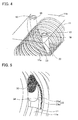
- Fig. 4 shows the end parts 14 and 15 of the circulation member 12.
- the paired end parts 14 and 15 are formed integral with the paired through holes 18 of the nut 11, respectively.
- the two end parts 14 and 15 are arranged and directed differently, but they have the same structures.
- the periphery of each of the end parts 14 and 15 includes a rolling groove connecting part 22 which is positioned to the loaded ball rolling groove 11a side of the nut 11 relative to the center line of the ball return path 13 in the end parts 14 and 15, and is linked to the loaded ball rolling groove 11a, and a scooping part 23 which is positioned to the ball rolling groove side of the screw shaft 1 relative to the center line of the ball return path 13 in the end parts 14 and 15 and scoops each ball from the loaded ball rolling path.
- the rolling groove connecting part 22 of each of the end parts 14 and 15 is required to be formed integral with the nut 11.
- the scooping part is also formed integral with the rolling groove connecting part 22, not only the rolling groove connecting part 22 but also the scooping part 23 is formed integral with the nut 11.
- FIG. 6(A) shows an comparative example in which the scooping part 23 and the loaded ball rolling groove 11a are misaligned. When they are misaligned (displaced from each other), balls 3 may bump unevenly into the scooping part 23 and therefore, smooth scooping of the balls 3 is prevented.
- each of the end parts 14 and 15 has the scooping part 23 jutting to the inside of the nut 11.
- the scooping part 23 has a boat bottom shaped scooping part 23a having a groove of which a width becomes narrower upward and toward the end parts 14, 15 and a lip-shaped spacer scooping part 23b which is in contact with each spacer 8 positioned between balls 3 to scoop the balls 3.
- the boat bottom shaped scooping part 23a holds each ball 3 rolling on the loaded ball rolling path to guide the ball 3 toward the inside of the end parts 14, 15.
- the spacer scooping part 23b comes into contact with the spacer 8 moving on the loaded ball rolling path and guides the spacer 8 to the inside of the end parts 14, 15.
- the spacer scooping part 23b is omitted.
- the boat bottom shaped scooping part 23a may be replaced with a lip-shaped ball scooping part which is in contact with each ball 3 to scoop up the ball 3 from the loaded ball rolling path.
- Fig. 7 shows dies for molding of the end parts 14 and 15.
- the die In order to form the scooping part 23, it is necessary to use the die to block the scooping part 23b jutting inside the nut 11 with the die.
- an axis shaped die 27 is arranged inside the nut.
- the axis shaped die 27 has a larger diameter than that of the screw shaft 1.
- a spiral groove 27a is formed on the outer peripheral surface thereof like the screw shaft 1. The groove 27a is used to form the end surface 24 of the spacer scooping part 23b.
- the outer peripheral surface 27b of the axis shaped die 27 is used to form the groove shape of the boat bottom shaped scooping part 23a.
- the spacer scooping part 23b juts in the groove 27a of the axis shaped die 27, the axis shaped die 27 should be removed from the nut 11 while rotating.
- the axis shaped die 27, which is drawn from the nut 11 needs to be returned into an axially fixed position of the nut 11.
- the axis shaped die 27 is drawn from the nut 11 rotatingly, attention should be given to the phase of the groove 27a of the axis shaped die 27 for forming the boat bottom shaped scooping part 23a and the spacer scooping part 23b, for example, by rotating the axis shaped die 27 backward through the same rotation angle.
- the spacer scooping part 23b is not provided on the scooping part 23 and only the boat bottom shaped scooping part 23a is provided. In this case, as there is no spacer scooping part jutting inside the groove 27a of the axis shaped die 27, the axis shaped die can be drawn from the nut without being rotated.
- a thin plate shaped die 28 bent into a cylinder is provided to shape the edges of the end parts 14 and 15. As shown in Fig. 5 , the boat bottom shaped scooping part 23a slightly juts from the nut 11. The thin plate shaped die 28 is slidingly inserted into a gap formed between the axis shaped die 27 and the nut 11 to fill in a gap of the jutting part at the lower end of the boat bottom shaped scooping part 23a. These thin plate shaped die 28 and axis shaped die 27 are arranged inside the nut 11 to shape the end parts 14 and 15 jutting to the inside of nut 11. Therefore, these thin plate shaped die 28 and axis shaped die 27 are called nut inside dies.
- a cross-sectionally arc shaped die 29 is inserted into each of the through holes 18 formed in the side surface of the nut 11. Then, of the outer peripheral surface of each of the end parts 14 and 15, a scooping-part-23 side outer peripheral surface 30 is formed (see Fig. 5 ).
- This outer peripheral surface 30 extends inside the thread bottom of the loaded ball rolling groove 11a of the nut 11. Even if the die is axially split into two and inserted into the nut 11 from the respective end sides of the nut 11, the outer peripheral surface 30 positioned in the thread bottom of the loaded ball rolling groove 11a of the nut cannot be formed. Hence, the cross-sectionally arc shaped die 29 is required to be inserted into the through hole 18.
- a notch 29a is formed conforming to the shape of the outer peripheral surface 27b of the axis shaped die 27, and a lip part 29b is formed to fit inside the groove 27a of the axis shaped die 27.
- a pin shaped die 33 is inserted into the through hole 18 formed on the side surface of the nut 11 to shape the ball return path 13 of each of the end parts 14 and 15.
- a lower end of the pin shaped die 33 fits into the groove 27a of the axis shaped die 27.
- the lower end of the pin shaped die 33 is chamfered conforming to the shape of the groove 27a of the axis shaped die 27 and conforming to the chamfered part of the loaded ball rolling groove 11a of the nut 11. Accordingly, the lower end of the pin shaped die 33 is precisely positioned relative to the loaded ball rolling groove 11a of the nut 11 and the axis shaped die 27.
- the lower end of the pin shaped die 33 is used to form the rolling groove connecting part 22 of the end parts 14 and 15. As the lower end of the pin shaped die 33 is positioned, the rolling groove connecting part 22 can be accurately formed and there is no elevation change formed at the joint 36 between the loaded ball rolling groove 11a of the nut 11 and the rolling groove connecting part 22.
- Figs. 8 and 9 show the dies seen from the inside of the nut 11, from which the axis shaped die 27 is removed.
- the edge 33a of the pin shaped die 33 and the lip part 29b of the cross-sectionally arc shaped die 29 are fit in the groove 27a of the axis shaped die 27.
- the groove 27a of the axis shaped die 27 is inclined in accordance with the lead of the screw shaft 1.
- the notch 29a of the cross-sectionally arc shaped die 29 is in contact with the outer peripheral surface 27b of the axis shaped die 27.
- the boat bottom shaped scooping part 23a of each of the end parts 14 and 15 is formed by the outer peripheral surface 27b of the axis shaped die 27, while the spacer scooping part 23b is formed by the groove 27a of the axis shaped die 27.
- the thin plate shaped die 28 is provided to fill the elevation change at the lower end of each of the end parts 14 and 15.
- These cross-sectionally arc shaped die 29, pin shaped die 33, axis shaped die 27 and thin plate shaped die 28 are used to form a cavity, which forms each of the end parts 14 and 15 of the circulation member 12.
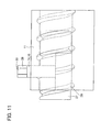
- Figs. 10 and 11 show assembly of all the dies.
- the axis shaped die 27 and the thin plate shaped die 28 are set inside the nut 11, and the cross-sectionally arc shaped die 29 and the pin shaped die 33 are inserted into the through hole 18, and then the cavity of each of the end parts 14 and 15 is formed.
- the end parts 14 and 15 are formed integral with the through hole.
- each of the end parts 14 and 15 jutting from the through hole 18 is also blocked with the die.
- the nut 11 becomes thinner at the flat surface part 11b, the nut 11 may be deformed with resin injected from the upper end surface of each of the end parts 14 and 15. For this reason, an insertion hole may be formed in an axial end surface 11c of the nut 11 for injecting resin toward the end parts 14 and 15.
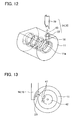
- Fig. 12 shows a nut of a screw device according to a second embodiment of the present invention.
- a rolling groove connecting part 37 of the periphery of each of end parts 34 and 35 of the circulation member is formed integral with the through hole 18 of the nut 11.
- the other scooping part 38 is resin-molded separately from the rolling groove connecting part 37 and fit into the through hole 18.
- Only the rolling groove connecting part 37 of each of the end parts 34 and 35 is linked to the loaded ball rolling groove 11a of the nut 11.
- the rolling groove connecting part 37 of each of the end parts 34, 35 is formed integral with the nut 11, there is no elevation change formed at the joint of the ball return path 13 and the loaded ball rolling groove 11a.
- the end parts 34 and 35 have the shape of half split, the die structure is simpler.
- Fig. 13 shows another example of the die.
- the end parts 14 and 15 are formed integral with the nut.
- a die 42 of small diameter provided with a movable part 41 is inserted into the nut 11. Once the die 42 is moved to a predetermined position of the nut 11, the movable part 41 is made to jut from the nut surface and block the scooping part 23 of the end parts 14 and 15.
- the movable part 41 has a shape conforming to the scooping part 23 jutting inside the nut 11. This example has an advantage of eliminating a need to use the die repeatedly.
- Fig. 14 shows another example of the axis shaped die.
- the axis shaped die 27 is provided with a ball 43 that can jut in the groove of the outer peripheral surface of the axis shaped die 27.
- a ball 43 is provided circumferentially at four parts of the axis shaped die 27, for example.
- the end parts 14 and 15 of the circulation member it is necessary to position the groove 27a of the axis shaped die 27 and the loaded ball rolling groove 11a of the nut 11 precisely. As shown in Fig.
- the end parts 14 and 15 of the circulation member 12 can be formed at the right positions of the nut 11.
- the rolling groove connecting part 22 is cut or grinded simultaneously with chamfering of the loaded ball rolling groove 11a after the end parts 14 and 15 are formed integral with the nut 11, there is surely no elevation change formed. Accordingly, after the end parts 14 and 15 of the circulation member 12 are formed integral with the nut 11, the rolling groove connecting part 22 may be cut or grinded with the loaded ball rolling groove 11a. Further, after the end parts 14 and 15 are molded into columns, the ball return path 13 is formed by cutting with a drill, and then, the scooping part 23 can be cut or grinded at the edges of the end parts 14 and 15.
- the present invention is not limited to the above-described embodiment and may be embodied in various formed without departing from the scope of the present invention.
- the through holes are formed in the side surface of the nut and the end parts of the circulation member are formed inside the through holes.
- the present invention is applicable to an endcap type screw device. That is, a notch is formed in an axially end surface of the nut and an end part of the circulation member is formed integrally with the notch.
- rollers may be used instead of balls.
- the resin molding may be replaced with MIM (Metal Injection Molding) which is injection molding of a mixture of binder and metal powder particles with use of a die.
- MIM Metal Injection Molding
- Figs. 16 and 17 show a nut 51 of a screw device according to a third embodiment of the present invention.
- Fig. 16 is a perspective view of the nut 51
- Fig. 17 is a cross sectional view.
- the nut 51 has an inner peripheral surface on which a spiral loaded ball rolling groove 51a is formed.
- the cross section of the loaded ball rolling groove 51a has a shape of a circular arc groove composed of a single arc or a Gothic arch groove composed of two arcs. As the balls roll on the loaded ball rolling groove 51a, the surface of the loaded ball rolling groove 51a is subjected to curing.
- a deflector hole 52 penetrating from the inner peripheral surface of the nut 51 to the outer peripheral surface.
- the deflector hole 52 is formed integral with a resin-made deflector 54.
- an almost S-shaped return groove 54a is formed connecting both ends of the loaded ball rolling groove 51a of less than one turn of the nut 51.
- the return groove 54a changes the moving direction of each ball rolling in the loaded ball rolling groove 51a of the nut 51, brings the ball 55 over a screw thread of the screw shaft and returns the ball one thread back to the loaded ball rolling groove 51a.
- the return groove 54a has a longitudinally center part which is most recessed so that each ball rolling in the return groove 54a can get over the screw thread of the screw shaft.
- the deflector 54 may be provided with a wing part 54b which is fit in the loaded ball rolling groove 51a of the nut 51 as shown in Fig. 17 , or such a wing part may not be formed as shown in Fig. 18 .
- Each ball moving in the lead angle direction of the screw shaft changes its direction when it is in touch with the wing part 54b.
- the deflector 54 can be reinforced.
- Figs. 19 to 21 show balls 55 moving on the screw shaft 53.
- Fig. 19 is a perspective view of the screw shaft 53
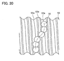
- Fig. 20 is a plane view of the screw shaft 53
- Fig. 21 is a view of the screw shaft 53 seen axially.
- On the outer peripheral surface of the screw shaft 53 a spiral ball rolling groove 53a is formed having a given lead.
- the ball rolling groove 53a has a shape of a circular arc groove composed of a single arc or a Gothic arch groove composed of two arcs.
- the screw shaft 53 may be one-thread, two-thread, three-thread screw shaft or the like. Between balls 55, a spacer is provided to prevent contact between the balls 55.
- each ball 55 rolling on the ball rolling groove 53a of the screw shaft 53 in the lead angle direction is made to change its direction toward the screw thread 53b by the return groove 54a of the deflector 54 and goes over the screw thread 53b.
- the ball 55 is returned one thread back to the ball rolling groove 53a.
- the raceway of the ball 55 in the return groove 54a has a shape conforming to the shape of the screw thread 53b.
- the return groove 54a of the deflector 54 is recessed at an outermost position of the raceway of the ball 55 rolling over the screw thread 53b.
- a loaded ball rolling path of less than one turn is formed between the loaded ball rolling groove 51a of less than one turn of the nut 51 and the ball rolling groove 53a of the screw shaft 53.
- an unloaded return path is formed between the return groove 54a of the deflector 54 and the screw shaft 53.
- These loaded ball rolling path and unloaded return path are used to form a one-turn ball circulation path.
- a plurality of deflectors 54 is provided circumferentially on the nut 51, and one-turn ball circulation paths are provided equal in number to the deflectors 54.
- Fig. 22 shows a cross section of the nut 51 taken along the return groove 54a of the deflector 54.
- the deflector 54 is formed integral with the deflector hole 52 of the nut 51 so that no elevation change is formed at the joint 58 of the return groove 54a of the deflector 54 and the loaded ball rolling groove 51a of the nut 51.
- an inner die and an outer die are mounted on the inner side and the outer side, respectively, of the deflector hole 52 of the nut 51 and molten resin is injected into the deflector hole 52.
- the deflector 54 is formed integral with the deflector hole 52. Therefore, there is no space formed between the outer peripheral surface of the deflector 54 and the inner peripheral surface of the deflector hole 52.
- the loaded ball rolling groove 51a is formed on the inner peripheral surface of the nut 51.
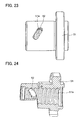
- the deflector hole 52 is formed at a circumferential part of the nut 51 as penetrating from the outer peripheral surface to the inner peripheral surface with use of a cutting tool such as an end mill.
- the plane surface of the deflector hole 52 has a rectangular center part and semicircular end parts.
- the deflector hole 52 is formed over adjacent loaded ball rolling grooves 51a.
- the deflector hole 52 is inclined with respect to the axial direction of the nut 51.
- a circumferential part of the nut 51 is only shown, however, the nut 51 is actually shaped like a cylinder as shown in Fig. 23 .
- Fig. 25 shows an outer die 60 mounted on the outer peripheral surface of the nut 51.
- the outer die 60 has a cylindrical nut contact surface 61 conforming to the shape of the outer peripheral surface of the nut 51, and a hole fitting convex part 62 conforming to the shape of the deflector hole 52 of the nut 51.
- the hole fitting convex part 62 of the outer die 60 is fit into the deflector hole 52 of the nut 51 thereby to position the outer die 60 relative to the nut 51.
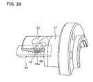
- Fig. 27 shows an inner die 64 mounted on the inner side of the nut 51.
- the inner die 64 has a nut contact surface 65 which can be in contact with the inner peripheral surface of the nut 51, a groove fitting convex part 66 conforming to the shape of the loaded ball rolling groove 51a of the nut 51, a hole fitting convex part 67 which is raised or bulges from the nut contact surface 65 and fit inside the deflector hole 52 of the nut 51, and a return groove convex part 68 provided inside the hole fitting convex part 67 to form the return groove 54a of the deflector 54.
- the groove fitting convex part 66 and the return groove convex part 68 are formed to be continuous.
- the inner die 64 has a leak proof convex part (not shown) for preventing molten resin injected in the deflector hole 52 from leaking from the loaded ball rolling groove 51a of the nut 51 (a part where the wing part 54b is fit and so on).
- the hole fitting convex part 67 of the inner die 64 is fit into the deflector hole 52 of the nut 51 and the groove fitting convex part 66 of the inner die 64 is fit into the loaded ball rolling groove 51a of the nut 51, and then, the inner die 64 can be positioned relative to the nut 51. If the inner die 64 cannot be positioned relative to the nut 51, the return groove 54a cannot be positioned at the right position.
- Fig. 29 shows the inner die 64 and the outer die 60 mounted on the inner peripheral side and outer peripheral side, respectively, of the nut 51.
- the nut 51 is moved axially and rotated, the nut 51 is sandwiched between the inner die 64 and the outer die 60.
- the outer die 60 and the inner die 64 are provided with the hole fitting convex parts 62 and 67, respectively, which are fit into the deflector holes 52 of the nut 51, both the inner die 64 and the outer die 60 can be positioned relative to the nut 51.
- One of the inner die 64 and the outer die 60 is provided with a gate. As molten resin is injected into the deflector hole 52 via the gate, the deflector 54 can be molded inside the deflector hole 52.
- the inner die 64 and the outer die 60 are shaped like axial splits of the cylindrical column, not like an approximately cylindrical column.
- the deflector hole 52 is formed passing through the nut 11 from the inner peripheral surface to the outer peripheral surface.
- the deflector hole 52 may be a blind hole extending from the inner peripheral surface of the nut 51 to a radially halfway to the outer side of the nut 51.
- the outer die 60 is omitted and the deflector 54 can be formed only with the inner die 64.
- the present invention is not limited to the above-described embodiments, but may be embodied in various forms without departing from the scope of the invention.
- the balls 55 may be replaced with rollers.
- Resin molding may be replaced with MIM (Metal Injection Molding) that is injection molding with a mixture of metal powder particles and binders with use of a die.
- MIM Metal Injection Molding
Landscapes
- Engineering & Computer Science (AREA)
- General Engineering & Computer Science (AREA)
- Mechanical Engineering (AREA)
- Manufacturing & Machinery (AREA)
- Transmission Devices (AREA)
- Injection Moulding Of Plastics Or The Like (AREA)
Abstract
Description
-
- A. The present invention relates to a return pipe type or endcap type screw device having a screw shaft, a nut, rolling elements rolling therebetween and a circulation member such as a return pipe or an endcap for circulating the rolling elements, and its manufacturing method.
- B. The present invention relates to a deflector type screw device having a screw shaft, a nut, rolling elements rolling therebetween and a deflector for returning the rolling elements one turn back to a loaded rolling-element rolling groove, and its manufacturing method.
In this description, the invention relating to the return pipe type or endcap type screw device and its manufacturing method is described with a mark of "A" and the invention relating the deflector type screw device and its manufacturing method is described with a mark of "B". -
- A. As a ball screw enables reduction of friction coefficient in rotating the screw shaft relative to the nut as compared with a sliding contact type screw, it has become commercially practical in various fields such as positioning mechanism of machine tools, vehicle steering, guide devices, motion screws and the like. As illustrated in
Fig. 30 , a return pipe type ball screw has a plurality ofballs 3 arranged in a loaded ball rolling path between a spiralball rolling groove 1a on the outer peripheral surface of ascrew shaft 1 and a spiral loadedball rolling groove 2a on the inner peripheral surface of anut 2, and theballs 3 are circulated in a ball return path of a U-shaped return pipe 4 (circulation member) formed in the nut 2 (for example, see patent document 1). In the side surface of thenut 2, a returnpipe insertion hole 2b is formed which extends up to the loadedball rolling groove 2a. When aleg part 4a of thereturn pipe 4 is inserted in the returnpipe insertion hole 2b, one end of the spiral loadedball rolling groove 2a of thenut 2 and the other end thereof are connected via the ball return path of thereturn pipe 4. Theplural balls 3 arranged between thenut 2 and thescrew shaft 1 circulate in a ball circulation path formed of the spiral loadedball rolling groove 2a and the ball return path in thereturn pipe 4. - Each
ball 3 moves from the loadedball rolling groove 2a of thenut 2 to the ball return path of thereturn pipe 4, and vice versa. At this time, if there is any elevation change (step height) at a joint of the loadedball rolling groove 2a of thenut 2 and the ball return path of thereturn pipe 4, theball 3 is prevented from moving smoothly. Accordingly, as shown inFig. 31 , in order to eliminate the elevation change at the joint 6 of theball return path 5 and the loadedball rolling groove 2a, a connecting part 7 of the loadedball rolling groove 2a to theball return path 5 is subjected to chamfering. Strictly speaking, in case of a ball screw using balls as rolling elements, the cross section of the loadedball rolling groove 2a is shaped like Gothic arch composed of two arcs so that each of the balls is in contact with the loadedball rolling groove 2a at two points. On the other hand, the cross section of theball return path 5 is shaped like a single arc. The connecting part 7 is also chamfered so that the cross section of the loadedball rolling groove 2a is changed gradually to conform to the cross section of theball return path 5 at the joint 6 thereof.
[Patent Document 1] Japanese Patent Laid-open Publication No.2000-18359 -
- B.
Fig. 32 illustrates a deflector type ball screw. Anut 71 has a side surface, in which adeflector hole 72 is formed. Adeflector 73 is fit in thedeflector hole 72. Thedeflector 73 has an S-shaped return groove 73a formed therein connecting both ends of a spiral loadedball rolling groove 71a of less than one turn formed in the inner peripheral surface of thenut 71. Thisreturn groove 73a acts to move eachball 75 away from aball rolling groove 76a of ascrew shaft 76, make theball 75 go over athread 76b of thescrew shaft 76 and return theball 75 one turn back to theball rolling groove 76a. Thedeflector 73 is a resin molding, and it is fit in thedeflector hole 72 of thenut 71 and secured to thenut 71 by an adhesive agent. - Meanwhile, the applicant has proposed a
wing type deflector 82 which can be inserted into anut 81 without any adhesive agent, as shown inFig. 33 (see the patent document 2). Thewing type deflector 82 has a deflectormain body 82a having areturn groove 82c formed therein and awing part 82b which juts from a side surface of the deflectormain body 82a and fits into the loadedball rolling groove 81a of thenut 81. Between thereturn groove 82c of thedeflector 82 and thescrew shaft 84, there areballs 85 arranged so that thedeflector 82 is prevented from falling into thescrew shaft 84 side.
[Patent Document 2] Japanese Patent Laid-open Publication No.2002-106672 -
- A. However, even if the loaded
ball rolling groove 2a and theball return path 5 are designed to eliminate the elevation change therebetween by chamfering, sometimes the U-shapedreturn pipe 4 is not manufactured as designed due to resin molding and bending, and pairedlegs 4a of thereturn pipe 4 may be deformed more inwardly or outwardly than designed. Besides, when aninsertion hole 2b of thereturn pipe 4 is formed from the side surface of thenut 2 toward the loadedball rolling groove 2a, the returnpipe insertion hole 2b is difficult to form straight. This is because the loadedball rolling groove 2a side of the returnpipe insertion hole 2b is thicker and the opposite side thereto is thinner so that if the returnpipe insertion hole 2b is tried to be formed straight, a drill is likely to move toward the thinner side. Accordingly, the returnpipe insertion hole 2b is difficult to form as designed. Such forming errors of thereturn pipe 4 and the returnpipe insertion hole 2b may cause elevation change at the joint 6. - When the elevation change is caused at the joint 6, smooth movement of the balls from the loaded
ball rolling groove 2a to theball return path 5 is prevented. Particularly, in a ball screw having spacers betweenballs 3, not only theballs 3 but also the spacers are caught in the elevation change. If the spacer is caught in the elevation change, the spacer is not able to control a space betweenballs 3, which causes circulation failure of theballs 3. - Then, the present invention has an object to provide a screw device capable of preventing occurrence of any elevation change at a joint between the loaded ball rolling groove of the nut and the ball return path of the circulation member and a method of manufacturing the same.
- B. However, in a screw device having a deflector mounted on the nut, loads from the
balls 75 may be repeatedly put on thedeflector 73, and coolant, cutting oil and the like may be splashed on thedeflector 73, resulting in reduction of strength of the adhesive agent. - In addition, as it is necessary to insert the
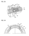
deflector 73 into thedeflector hole 72 before adhesion, the outer shape of thedeflector 73 is slightly smaller than thedeflector hole 72. Hence, as shown inFig. 34 , there is a small space between thedeflector 73 and the inner wall surface of thedeflector hole 72. As the operation of adhering thedeflector 73 to thenut 71 is performed manually by human operators, thedeflector 73 is sometimes misaligned. This may causes a space or elevation change at thejoint 78 of the loadedball rolling groove 71a of thenut 71 and thereturn groove 73a of thedeflector 73. - For a wing-
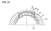
type deflector 82, as shown inFig. 35 , there is a space formed between thedeflector 82 and adeflector hole 88 so that the deflector can swing during operation. Swinging of thedeflector 82 makes it possible to reduce bumps of the balls into thedeflector 82. However, when thedeflector 82 has swung, or being inclined, from the state indicated by the slid line in the figure to the state indicated by the broken line in the figure, there occur a space, elevation change and the like at thejoint 86 of thereturn groove 82c of thedeflector 82 and the loadedball rolling groove 81a of thenut 81. The elevation change and space at the joint may prevent smooth movement of the balls. - Further, in the wing-
type deflector 82, theballs 85 interposed between thescrew shaft 84 and thereturn groove 82c of thedeflector 82 act to prevent thedeflector 82 from falling toward thescrew shaft 84. However, just when pairedadjacent balls 85 are moving over one side face of a thread, thedeflector 82 slightly falls toward thescrew shaft 84 side. When thedeflector 82 falls toward thescrew shaft 84, there occurs an elevation change at thejoint 86 between thereturn groove 82c of thedeflector 82 and the loadedball rolling groove 81a of thenut 81, and theballs 85 bump into the end part of thereturn groove 82c of thedeflector 82. In order to prevent this, clearance is formed at the end part of thereturn groove 82c so that when thedeflector 82 falls toward thescrew shaft 84, theballs 85 do not bump into the end part of thereturn groove 82c. However, if the clearance is formed at the end part of thereturn groove 82c, when thedeflector 82 is raised, the clearance formed for preventing the elevation change may cause another elevation change. - Then, the present invention has an object to provide a screw device capable of preventing occurrence of an elevation change at a joint between the loaded ball rolling groove of the nut and the ball return groove of the deflector and a method of manufacturing the same.
- The present invention will now be described as follows.
- In order to solve the above-mentioned problems, the invention of
claim 1 is a screw device comprising: a screw shaft having an outer peripheral surface with a rolling-element rolling groove spirally formed thereon; a nut having an inner peripheral surface with a loaded rolling-element rolling groove spirally formed thereon facing the rolling-element rolling groove of the screw shaft; a circulation member having a rolling-element return path connecting one end of the loaded rolling-element rolling groove of the nut with an opposite end thereof; and a plurality of rolling elements arranged in the rolling-element return path of the circulation member and a loaded rolling-element rolling path between the rolling-element rolling groove of the screw shaft and the loaded rolling-element rolling groove of the nut, the rolling elements rolling in the loaded rolling-element rolling path, being scooped up at an end part of the circulation member and returned into the loaded rolling-element rolling path by an opposite end part of the circulation member, the end part of the circulation member having an periphery including a rolling groove connecting part which is positioned to a side of the loaded rolling-element rolling groove of the nut and connected to the loaded rolling-element rolling groove of the nut and a scooping part which is positioned to a side of the rolling-element rolling groove of the screw shaft and scoops up the rolling elements from the loaded rolling-element rolling path, and at least the rolling groove connecting part of the end part being made of resin and formed integral with the nut. - The invention of
claim 2 is characterized in that, in the screw device ofclaim 1, the scooping part of the end part of the circulation member is made of resin and formed integral with the rolling groove connecting part. - The invention of
claim 3 is characterized in that, in the screw device ofclaim - The invention of
claim 4 is characterized in that, in the screw device ofclaim 3, a space is formed between the inner peripheral surface of the through hole and an outer peripheral surface of the scooping part of the end part so that a die is inserted into the space. - The invention of
claim 5 is characterized in that, in the screw device ofclaim - The invention of claim 6 is characterized in that, in the screw device of any one of
claims 1 to 5, a spacer is interposed to prevent contact between the rolling elements. - The invention of claim 7 is characterized in that, in the screw device of
claim - The invention of
claim 8 is a method of manufacturing a screw device having: a screw shaft having an outer peripheral surface with a rolling-element rolling groove spirally formed thereon; a nut having an inner peripheral surface with a loaded rolling-element rolling groove spirally formed thereon facing the rolling-element rolling groove of the screw shaft; a circulation member having a rolling-element return path connecting one end of the loaded rolling-element rolling groove of the nut with an opposite end thereof; and a plurality of rolling elements arranged in the rolling-element return path of the circulation member and a loaded rolling-element rolling path between the rolling-element rolling groove of the screw shaft and the loaded rolling-element rolling groove of the nut, the rolling elements rolling in the loaded rolling-element rolling path, being scooped up at an end part of the circulation member and returned into the loaded rolling-element rolling path by an opposite end part of the circulation member, the end part of the circulation member having an periphery including a rolling groove connecting part which is positioned to a side of the loaded rolling-element rolling groove of the nut and connected to the loaded rolling-element rolling groove of the nut and a scooping part which is positioned to a side of the rolling-element rolling groove of the screw shaft and scoops up the rolling elements from the loaded rolling-element rolling path, the method comprising: inserting the nut into a die to form at least the rolling groove connecting part of the end part integral with the nut by resin insert molding. - The invention of claim 9 is characterized in that, in the method of
claim 8, the scooping part of the end part of the circulation member is formed integral with the rolling groove connecting part with resin. - The invention of claim 10 is characterized in that, in the method of
claim 8 or 9, a through hole is formed in a side surface of the nut so as to reach the loaded rolling-element rolling groove of the inner peripheral surface of the nut, and at least the rolling groove connecting part of the end part of the circulation member is formed integral with an inner surface of the through hole. - The invention of
claim 11 is characterized in that, in the method of any one ofclaims 8 to 10, the die includes a nut inside die which is placed inside the nut to form the end part of the circulation member jutting inside the nut. - The invention of
claim 12 is characterized in that, in the method of any one ofclaims 8 to 11, the die includes a pin shaped die which is inserted in a through hole formed in a side surface of the nut to form the rolling-element return path of the end part of the circulation member. - The invention of
claim 13 is characterized in that, in the method of any one ofclaims 8 to 12, the die includes a cross-sectionally arc shaped die which is inserted in a through hole formed in a side surface of the nut to form a scooping-part-side outer peripheral surface of an outer peripheral surface of the end part of the circulation member. - The invention of
claim 14 is characterized in that, in the method of any one ofclaims 8 to 13, the rolling groove connecting part of the end part of the circulation member is formed of resin and integral with the nut before the rolling groove connecting part and the loaded rolling-element rolling groove of the nut are subjected to cutting and grinding. - The invention of
claim 15 is a screw device comprising: a screw shaft having an outer peripheral surface with a rolling-element rolling groove spirally formed thereon; a nut having an inner peripheral surface with a loaded rolling-element rolling groove spirally formed thereon facing the rolling-element rolling groove of the screw shaft; a deflector having a return groove connecting one end of the loaded rolling-element rolling groove of less than one turn of the nut with an opposite end thereof; and a plurality of rolling elements arranged in a rolling-element circulation path of one turn including the return groove and the loaded rolling-element rolling groove of less than one turn, the rolling elements rolling in a loaded rolling-element rolling path between the rolling-element rolling groove of the screw shaft and the loaded rolling-element rolling groove of less than one turn of the nut and being circulated via the deflector, wherein the deflector is made of resin and is formed integral with the nut so as to prevent occurrence of elevation change at a joint of the loaded rolling-element rolling groove of the nut and the return groove of the deflector. - The invention of claim 16 is a method of manufacturing a nut having an inner peripheral surface with a loaded rolling-element rolling groove of less than one turn spirally formed thereon n such a manner as to be integral with a deflector of resin having a return groove connecting one end of the loaded rolling-element rolling groove of less than one turn of the nut with an opposite end thereof, the method comprising: a deflector hole forming step of forming in the nut a deflector hole which conforms to a shape of the deflector; a die mounting step of inserting into the nut an inner die having a groove fitting convex part which conforms to a shape of the loaded rolling-element rolling groove of the nut and a return groove convex part which is continuous to the groove fitting convex part and is for forming the return groove of the deflector, and of fitting the groove fitting convex part of the inner die into the loaded rolling-element rolling groove of the nut; and a forming step of performing injection-molding of resin in the deflector hole of the nut to which the inner die is inserted.
- The invention of
claim 17 is a method of manufacturing a nut having an inner peripheral surface with a loaded rolling-element rolling groove of less than one turn spirally formed thereon in such a manner as to be integral with a deflector of resin having a return groove connecting one end of the loaded rolling-element rolling groove of less than one turn of the nut with an opposite end thereof, the method comprising: a deflector hole forming step of forming in the nut a deflector hole which conforms to a shape of the deflector; a die mounting step of inserting into the nut an inner die having a hole fitting convex part which conforms to a shape of the deflector hole of the nut and a return groove convex part which is provided in the hole fitting convex part to form the return groove of the deflector, and of fitting the hole fitting convex part of the inner die into the deflector hole of the nut; and a forming step of performing injection-molding of resin in the deflector hole of the nut to which the inner die is inserted. - The invention of
claim 18 is characterized in that in the method ofclaim 16 or 17, in the deflector hole forming step, the deflector hole is formed passing through the nut from an inner peripheral side to an outer peripheral side thereof; in the die mounting step, an outer die is mounted on an outer side of the nut; and in the forming step, the resin is injected into the deflector hole of the nut on which the inner die and the outer die are mounted. - According to the invention of
claim 1, as the rolling groove connecting part of the circulation member is formed integral with the nut, it becomes possible to prevent occurrence of elevation change between the loaded rolling-element rolling groove of the nut and the rolling groove connecting part of the circulation member. - According to the invention of
claim 2, as the scooping part of the circulation member is prevented from being misaligned relative to the nut, it becomes possible to scoop the rolling elements from the loaded rolling-element rolling path smoothly. - According to the invention of
claim 3, it becomes possible to prevent occurrence of elevation change between the loaded rolling-element rolling groove of the nut and the rolling groove connecting part of the circulation member even if there is variation in forming accuracy of the through hole. - According to the invention of
claim 4, it becomes possible to form the scooping part of the circulation member in the through hole of the nut. - According to the invention of
claim 5, it is possible to form the connecting return path in the circulation member for circulation the rolling elements. - According to the invention of claim 6, the spacer interposed between the rolling elements smoothly move from the loaded rolling-element rolling groove of the nut to the rolling groove connecting part of the circulation member.
- According to the invention of claim 7, it becomes possible to prevent occurrence of elevation change between the loaded rolling-element rolling groove of the nut and the rolling groove connecting part of the deflector even if there is variation in forming accuracy of the deflector hole.
- According to the invention of
claim 8, as the rolling groove connecting part of the circulation member is formed integral with the nut, it becomes possible to prevent occurrence of elevation change between the loaded rolling-element rolling groove of the nut and the rolling groove connecting part of the circulation member. - According to the invention of claim 9, as the scooping part is prevented from being misaligned relative to the nut, it becomes possible to scoop the rolling elements from the loaded rolling-element rolling path smoothly.
- According to the invention of claim 10, it becomes possible to prevent occurrence of elevation change between the loaded rolling-element rolling groove of the nut and the rolling groove connecting part of the circulation member even if there is variation in forming accuracy of the through hole.
- According to the invention of
claim 11, it is possible to use the nut inside die to form the end part of the circulation member jutting inside the die. - According to the invention of
claim 12, it is possible to use the pin shaped die to form the rolling-element return path of the end part of the circulation member. - According to the invention of
claim 13, it is possible to use the cross-sectionally arc shaped die to form the scooping-part-side outer peripheral surface of the outer peripheral surface of the end part of the circulation member. - According to the invention of
claim 14, it is possible to further prevent occurrence of elevation change between the loaded rolling-element rolling groove of the nut and the rolling groove connecting part of the circulation member. - According to the invention of
claim 15, it becomes possible to eliminate space and elevation change at the joint between the loaded rolling-element rolling groove of the nut and the return groove of the deflector. - According to the invention of claim 16, as the deflector is formed using the inner die having the groove fitting convex part which conforms to the shape of the loaded rolling-element rolling groove of the nut and the return groove convex part which is continuous to the groove fitting convex part, it is possible to prevent occurrence of elevation change at the joint between the loaded rolling-element rolling groove of the nut and the return groove of the deflector.
- According to the invention of
claim 17, as the inner die having the return groove convex part for forming the return groove of the deflector can be aligned relative to the nut accurately, it is possible to form the return groove of the deflector at a predetermined position inside the deflector hole accurately. - According to the invention of
claim 18, the deflector hole can be formed easier than a blind deflector hole formed in the inner peripheral side of the nut to form the deflector with use of the inner die only. -
-
Fig. 1 is a perspective view of a nut of a screw device according to a first embodiment of the present invention. -
Fig. 2 is a perspective view of the nut of the screw device according to the first embodiment of the present invention (connecting part components are shown separated). -
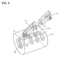
Fig. 3 is a perspective view of a nut of the screw device according to a first embodiment of the present invention (connecting part components are shown separated). -
Fig. 4 is a perspective view of an end part of the circulation member. -
Fig. 5 is a perspective view of a scooping part exposed inside the nut. -
Figs. 6(A) and 6(B) are views each showing a positional relation between the loaded ball rolling groove of the nut and - the scooping part (
Fig. 6(A) showing they are displaced from each other andFig. 6(B) showing they match each other). -
Fig. 7 is a perspective view of the nut and dies. -
Fig. 8 is a view showing the dies from which an axis shaped die is removed. -
Fig. 9 is a view showing the dies from which the axis shaped die is removed. -
Fig. 10 is a view showing a die assembly. -
Fig. 11 is a view showing a die assembly. -
Fig. 12 is a perspective view of a nut of a screw device according to a second embodiment of the present invention. -
Fig. 13 is a cross sectional view of another example of the die. -
Fig. 14 is a view showing another example of the axis shaped die. -
Fig. 15 is a view showing the operation of a ball fit in the groove of the axis shaped die. -
Fig. 16 is a perspective view of a nut of a screw device according to a third embodiment of the present invention. -
Fig. 17 is a cross sectional view of the nut inFig. 16 (wing deflector). -
Fig. 18 is a cross sectional view of the nut inFig. 16 (typical deflector). -
Fig. 19 is a view showing balls moving on the screw shaft (perspective view of the screw shaft). -
Fig. 20 is a view showing balls moving on the screw shaft (plane view of the screw shaft). -
Fig. 21 is a view showing balls moving on the screw shaft (front view of the screw shaft). -
Fig. 22 is a cross sectional view of the nut taken along the return groove of the deflector. -
Fig. 23 is a perspective view of the nut having a deflector hole formed therein. -
Fig. 24 is a cross sectional view of the nut having a deflector hole formed therein. -
Fig. 25 is a perspective view of an outer die. -
Fig. 26 is a view showing the outer die fit on the nut. -
Fig. 27 is a perspective view of an inner die. -
Fig. 28 is a view showing the inner die fit on the nut. -
Fig. 29 is a view showing the inner die and the outer die fit on the nut. -
Fig. 30 is a perspective view illustrating a conventional ball screw. -
Fig. 31 is a cross sectional view showing a connecting part of a ball return path and a loaded ball rolling groove. -
Fig. 32 is a perspective view of a conventional deflector type ball screw. -
Fig. 33 is a perspective view showing a conventional wing deflector type ball screw. -
Fig. 34 is a cross sectional view of the conventional deflector type ball screw. -
Fig. 35 is a cross sectional view of the conventional wing deflector type ball screw. -
- 1
- screw shaft
- 1a
- ball rolling groove (rolling-element rolling groove)
- 3
- ball (rolling element)
- 8
- spacer
- 11
- nut
- 11a
- loaded ball rolling groove (loaded rolling-element rolling groove)
- 12
- circulation member
- 13
- ball return path (rolling-element return path)
- 14, 15, 34, 35
- end part
- 17
- connecting part
- 18
- through hole
- 19
- connecting return path
- 22, 37
- rolling groove connecting part
- 23, 38
- scooping part
- 23a
- boat bottom shaped scooping part
- 23b
- spacer scooping part
- 27
- axis shaped die (nut inside die)
- 28
- thin plate shaped die (nut inside die)
- 29
- cross-sectionally arc shaped die
- 33
- pin shaped die
- 51
- nut
- 51a
- loaded ball rolling groove (loaded rolling-element rolling groove)
- 53
- screw shaft
- 53a
- ball rolling groove (rolling-element rolling groove)
- 54
- deflector
- 54a
- return groove
- 55
- ball (rolling element)
- 58
- joint part
- 60
- outer die
- 64
- inner die
- 66
- groove fitting convex part
- 67
- hole fitting convex part
- 68
- return groove convex part
-
- A.
Figs. 1 to 3 show a nut of a screw device according to a first embodiment of the present invention.Fig. 1 shows thenut 11 with acirculation member 12 mounted thereon, whileFigs. 2 and3 show thenut 11 with thecirculation member 12 disassembled. In an inner peripheral surface of thenut 11, there is formed a spiral loaded ball rolling groove as a loaded rolling-element rolling groove facing a rolling-element rolling groove of a screw shaft. Inside thenut 11, the screw shaft is inserted which has a spiral ball rolling groove as the rolling-element rolling groove formed on the outer peripheral surface thereof. Between the ball rolling groove of the screw shaft and the loadedball rolling groove 11a of thenut 11, a plurality of balls is arranged and accommodated as rolling elements. - As the structures of the screw shaft and a ball are the same as those of the conventional ball screw shown in
Fig. 17 , they are described with the same reference numerals as those assigned inFig. 17 . On the outer peripheral surface of thescrew shaft 1, theball rolling groove 1a is formed having a given lead. Theball rolling groove 1a is formed having a circular arc shaped cross section composed of a single arc or a Gothic arch shaped cross section composed of two arcs. Asballs 3 roll on theball rolling groove 1a of thescrew shaft 1, theball rolling groove 1a has its surface subjected to curing. Thescrew shaft 1 may be one-thread, two-thread or three-thread screw or the like. Betweenballs 3, aspacer 8 is arranged to prevent contact between theballs 3. - The
screw shaft 1 is inserted intonut 11. As shown inFig. 1 , the spiral loadedball rolling groove 11a is formed on the inner peripheral surface of thenut 11, facing theball rolling groove 1a of thescrew shaft 1. The cross section of the loadedball rolling groove 11 is shaped like a circular arc composed of a single arc or a Gothic arch composed of two arcs. As theballs 3 roll on the loadedball rolling groove 11a, the loadedball rolling groove 11a has its surface subjected to curing. Thenut 11 has a side surface on which aflat surface part 11b is formed. - On the
flat surface part 11b of thenut 11, acirculation member 12 is provided for circulating theballs 3 rolling on a loaded ball rolling path between theball rolling groove 1a of thescrew shaft 1 and the loadedball rolling groove 11a of thenut 11. Thecirculation member 12 has aball return path 13 formed therein as a rolling-element return path connecting one end of the loadedball rolling groove 11a of thenut 11 to the other (seeFig. 2 ). These loaded ball rolling path and ball returnpath 13 form a ball circulation path where theplural balls 3 are arranged. - When the
screw shaft 1 is rotated relative to thenut 11, theballs 3 roll between the loadedball rolling groove 11a of thenut 11 and theball rolling groove 1a of thescrew shaft 1. Once rolling up to an end of the loaded ball rolling path, eachball 3 is scooped up from the loaded ball rolling path into theball return path 13 by anend part 14 of thecirculation member 12. The inner diameter of theball return path 13 is slightly larger than the diameter of eachball 3. On theball return path 13, aball 3 moves pushed by its followingball 3. After moving on theball return path 13, theball 3 is returned, via theother end part 15 of the circulation member, several-thread back to the other end of the loaded ball rolling path. All the while thescrew shaft 1 is rotated relative to thenut 11, theballs 3 endlessly circulate on the ball circulation path including the loaded ball rolling path and theball return path 13. - As shown in
Fig. 2 , thecirculation member 12 has a pair ofend parts part 17 jutting from theflat surface part 11b and connecting the pairedend parts end parts ball return paths ball return paths flat surface part 11b, there are formed throughholes 18 reaching the loadedball rolling groove 11a of thenut 11. Theend parts circulation member 12 are made of resin and formed integral with the inner peripheral surfaces of these throughholes 18. - The connecting
part 17 is a resin-molded component. The connectingpart 17 has a U-shaped connectingreturn path 19 formed connecting theball return paths end parts return path 19 has acenter return path 19a straightly extending from oneend part 14 of thecirculation member 12 toward theother end part 15 andend return paths 19b provided at the respective ends of the center returnpath 19a and bent into arc. The connectingpart 17 is split into two along the center line of theball return path 13 and each split component has a juttingpart 20 formed integrally. The juttingpart 20 has a retainingscrew insertion part 21 in which a retaining screw is inserted for fastening the connectingpart 17 to the side surface of thenut 11. -
Fig. 4 shows theend parts circulation member 12. The pairedend parts holes 18 of thenut 11, respectively. The twoend parts end parts groove connecting part 22 which is positioned to the loadedball rolling groove 11a side of thenut 11 relative to the center line of theball return path 13 in theend parts ball rolling groove 11a, and a scoopingpart 23 which is positioned to the ball rolling groove side of thescrew shaft 1 relative to the center line of theball return path 13 in theend parts end parts ball rolling groove 11a of thenut 11, at least the rollinggroove connecting part 22 of each of theend parts nut 11. In this embodiment, as the scooping part is also formed integral with the rollinggroove connecting part 22, not only the rollinggroove connecting part 22 but also the scoopingpart 23 is formed integral with thenut 11. When the scooping part is integral with the nut, as shown inFig. 6(B) , the scoopingpart 23 is prevented from being displaced from the loadedball rolling groove 11a of thenut 11. Hence,balls 3 are scooped up smoothly.
Fig. 6(A) shows an comparative example in which the scoopingpart 23 and the loadedball rolling groove 11a are misaligned. When they are misaligned (displaced from each other),balls 3 may bump unevenly into the scoopingpart 23 and therefore, smooth scooping of theballs 3 is prevented. - As shown in
Fig. 5 , each of theend parts part 23 jutting to the inside of thenut 11. The scoopingpart 23 has a boat bottom shaped scoopingpart 23a having a groove of which a width becomes narrower upward and toward theend parts spacer scooping part 23b which is in contact with eachspacer 8 positioned betweenballs 3 to scoop theballs 3. The boat bottom shaped scoopingpart 23a holds eachball 3 rolling on the loaded ball rolling path to guide theball 3 toward the inside of theend parts spacer scooping part 23b comes into contact with thespacer 8 moving on the loaded ball rolling path and guides thespacer 8 to the inside of theend parts balls 3, thespacer scooping part 23b is omitted. Further, the boat bottom shaped scoopingpart 23a may be replaced with a lip-shaped ball scooping part which is in contact with eachball 3 to scoop up theball 3 from the loaded ball rolling path. -
Fig. 7 shows dies for molding of theend parts part 23, it is necessary to use the die to block the scoopingpart 23b jutting inside thenut 11 with the die. In order to form the screw-shaft-1side end surface 24 of thespacer scooping part 23b and the groove of the boat bottom shaped scoopingpart 23a shown inFig. 5 , an axis shaped die 27 is arranged inside the nut. The axis shaped die 27 has a larger diameter than that of thescrew shaft 1. In the axis shaped die 27, aspiral groove 27a is formed on the outer peripheral surface thereof like thescrew shaft 1. Thegroove 27a is used to form theend surface 24 of thespacer scooping part 23b. Then, the outerperipheral surface 27b of the axis shaped die 27 is used to form the groove shape of the boat bottom shaped scoopingpart 23a. As after molding, thespacer scooping part 23b juts in thegroove 27a of the axis shaped die 27, the axis shaped die 27 should be removed from thenut 11 while rotating. In case of continuous working, in order that the boat bottom shaped scoopingpart 23a and thespacer scooping part 23b can be molded at the fixed position of thenut 11, the axis shaped die 27, which is drawn from thenut 11, needs to be returned into an axially fixed position of thenut 11. Here, if the axis shaped die 27 is drawn from thenut 11 rotatingly, attention should be given to the phase of thegroove 27a of the axis shaped die 27 for forming the boat bottom shaped scoopingpart 23a and thespacer scooping part 23b, for example, by rotating the axis shaped die 27 backward through the same rotation angle. However, for the full ball type ball screw having nospacer 8 betweenballs 3, thespacer scooping part 23b is not provided on the scoopingpart 23 and only the boat bottom shaped scoopingpart 23a is provided. In this case, as there is no spacer scooping part jutting inside thegroove 27a of the axis shaped die 27, the axis shaped die can be drawn from the nut without being rotated. - A thin plate shaped die 28 bent into a cylinder is provided to shape the edges of the
end parts Fig. 5 , the boat bottom shaped scoopingpart 23a slightly juts from thenut 11. The thin plate shaped die 28 is slidingly inserted into a gap formed between the axis shaped die 27 and thenut 11 to fill in a gap of the jutting part at the lower end of the boat bottom shaped scoopingpart 23a. These thin plate shaped die 28 and axis shaped die 27 are arranged inside thenut 11 to shape theend parts nut 11. Therefore, these thin plate shaped die 28 and axis shaped die 27 are called nut inside dies. - A cross-sectionally arc shaped die 29 is inserted into each of the through
holes 18 formed in the side surface of thenut 11. Then, of the outer peripheral surface of each of theend parts peripheral surface 30 is formed (seeFig. 5 ). This outerperipheral surface 30 extends inside the thread bottom of the loadedball rolling groove 11a of thenut 11. Even if the die is axially split into two and inserted into thenut 11 from the respective end sides of thenut 11, the outerperipheral surface 30 positioned in the thread bottom of the loadedball rolling groove 11a of the nut cannot be formed. Hence, the cross-sectionally arc shaped die 29 is required to be inserted into the throughhole 18. At the bottom of the cross-sectionally arc shaped die 29, anotch 29a is formed conforming to the shape of the outerperipheral surface 27b of the axis shaped die 27, and alip part 29b is formed to fit inside thegroove 27a of the axis shaped die 27. After molding of theend parts nut 11. Then, between the inner peripheral surface of the throughhole 18 and the scooping-part-23 side outerperipheral surface 30 of each of theend parts end parts nut 11 is not sufficiently strong, any material of the same shape as this space may be positioned in the space. - A pin shaped die 33 is inserted into the through
hole 18 formed on the side surface of thenut 11 to shape theball return path 13 of each of theend parts groove 27a of the axis shaped die 27. The lower end of the pin shaped die 33 is chamfered conforming to the shape of thegroove 27a of the axis shaped die 27 and conforming to the chamfered part of the loadedball rolling groove 11a of thenut 11. Accordingly, the lower end of the pin shaped die 33 is precisely positioned relative to the loadedball rolling groove 11a of thenut 11 and the axis shaped die 27. The lower end of the pin shaped die 33 is used to form the rollinggroove connecting part 22 of theend parts groove connecting part 22 can be accurately formed and there is no elevation change formed at the joint 36 between the loadedball rolling groove 11a of thenut 11 and the rollinggroove connecting part 22. -
Figs. 8 and9 show the dies seen from the inside of thenut 11, from which the axis shaped die 27 is removed. Theedge 33a of the pin shaped die 33 and thelip part 29b of the cross-sectionally arc shaped die 29 are fit in thegroove 27a of the axis shaped die 27. Thegroove 27a of the axis shaped die 27 is inclined in accordance with the lead of thescrew shaft 1. Thenotch 29a of the cross-sectionally arc shaped die 29 is in contact with the outerperipheral surface 27b of the axis shaped die 27. The boat bottom shaped scoopingpart 23a of each of theend parts peripheral surface 27b of the axis shaped die 27, while thespacer scooping part 23b is formed by thegroove 27a of the axis shaped die 27. The thin plate shaped die 28 is provided to fill the elevation change at the lower end of each of theend parts end parts circulation member 12. -
Figs. 10 and11 show assembly of all the dies. The axis shaped die 27 and the thin plate shaped die 28 are set inside thenut 11, and the cross-sectionally arc shaped die 29 and the pin shaped die 33 are inserted into the throughhole 18, and then the cavity of each of theend parts end parts - The upper end surface of each of the
end parts hole 18 is also blocked with the die. When thenut 11 becomes thinner at theflat surface part 11b, thenut 11 may be deformed with resin injected from the upper end surface of each of theend parts axial end surface 11c of thenut 11 for injecting resin toward theend parts -
Fig. 12 shows a nut of a screw device according to a second embodiment of the present invention. In this embodiment, only a rollinggroove connecting part 37 of the periphery of each of end parts 34 and 35 of the circulation member is formed integral with the throughhole 18 of thenut 11. The other scoopingpart 38 is resin-molded separately from the rollinggroove connecting part 37 and fit into the throughhole 18. Only the rollinggroove connecting part 37 of each of the end parts 34 and 35 is linked to the loadedball rolling groove 11a of thenut 11. Hence, if at least the rollinggroove connecting part 37 of each of the end parts 34, 35 is formed integral with thenut 11, there is no elevation change formed at the joint of theball return path 13 and the loadedball rolling groove 11a. In this embodiment, as the end parts 34 and 35 have the shape of half split, the die structure is simpler. -
Fig. 13 shows another example of the die. As described above, if the scoopingpart 23 jutting inside thenut 11 shown inFig. 5 is blocked, theend parts die 42 of small diameter provided with amovable part 41 is inserted into thenut 11. Once thedie 42 is moved to a predetermined position of thenut 11, themovable part 41 is made to jut from the nut surface and block the scoopingpart 23 of theend parts movable part 41 has a shape conforming to the scoopingpart 23 jutting inside thenut 11. This example has an advantage of eliminating a need to use the die repeatedly. -
Fig. 14 shows another example of the axis shaped die. In this example, the axis shaped die 27 is provided with aball 43 that can jut in the groove of the outer peripheral surface of the axis shaped die 27. Such aball 43 is provided circumferentially at four parts of the axis shaped die 27, for example. In order that theend parts groove 27a of the axis shaped die 27 and the loadedball rolling groove 11a of thenut 11 precisely. As shown inFig. 15 , when theball 43 is made to jut from thegroove 27a of the axis shaped die 27 to fit to the loadedball rolling groove 11a of thenut 11, thegroove 27a of the axis shaped die 27 and the loadedball rolling groove 11a of thenut 11 are positioned precisely. Accordingly, theend parts circulation member 12 can be formed at the right positions of thenut 11. When the axis shaped die 27 is drawn from thenut 11, theballs 43 sit back. - Here, if the rolling
groove connecting part 22 is cut or grinded simultaneously with chamfering of the loadedball rolling groove 11a after theend parts nut 11, there is surely no elevation change formed. Accordingly, after theend parts circulation member 12 are formed integral with thenut 11, the rollinggroove connecting part 22 may be cut or grinded with the loadedball rolling groove 11a. Further, after theend parts ball return path 13 is formed by cutting with a drill, and then, the scoopingpart 23 can be cut or grinded at the edges of theend parts - Here, the present invention is not limited to the above-described embodiment and may be embodied in various formed without departing from the scope of the present invention. For example, in the above-described embodiment, like a return pipe type screw device, the through holes are formed in the side surface of the nut and the end parts of the circulation member are formed inside the through holes. However, the present invention is applicable to an endcap type screw device. That is, a notch is formed in an axially end surface of the nut and an end part of the circulation member is formed integrally with the notch. As rolling elements, rollers may be used instead of balls. Further, the resin molding may be replaced with MIM (Metal Injection Molding) which is injection molding of a mixture of binder and metal powder particles with use of a die.
- B.
Figs. 16 and 17 show anut 51 of a screw device according to a third embodiment of the present invention.Fig. 16 is a perspective view of thenut 51, andFig. 17 is a cross sectional view. Thenut 51 has an inner peripheral surface on which a spiral loadedball rolling groove 51a is formed. The cross section of the loadedball rolling groove 51a has a shape of a circular arc groove composed of a single arc or a Gothic arch groove composed of two arcs. As the balls roll on the loadedball rolling groove 51a, the surface of the loadedball rolling groove 51a is subjected to curing. - At a circumferential part of the
nut 51, there is formed adeflector hole 52 penetrating from the inner peripheral surface of thenut 51 to the outer peripheral surface. Thedeflector hole 52 is formed integral with a resin-madedeflector 54. At the bottom surface of thedeflector 54, an almost S-shapedreturn groove 54a is formed connecting both ends of the loadedball rolling groove 51a of less than one turn of thenut 51. Thereturn groove 54a changes the moving direction of each ball rolling in the loadedball rolling groove 51a of thenut 51, brings theball 55 over a screw thread of the screw shaft and returns the ball one thread back to the loadedball rolling groove 51a. Thereturn groove 54a has a longitudinally center part which is most recessed so that each ball rolling in thereturn groove 54a can get over the screw thread of the screw shaft. - The
deflector 54 may be provided with awing part 54b which is fit in the loadedball rolling groove 51a of thenut 51 as shown inFig. 17 , or such a wing part may not be formed as shown inFig. 18 . Each ball moving in the lead angle direction of the screw shaft changes its direction when it is in touch with thewing part 54b. As thewing part 54b is formed in thedeflector 54, thedeflector 54 can be reinforced. -
Figs. 19 to 21 show balls 55 moving on thescrew shaft 53.Fig. 19 is a perspective view of thescrew shaft 53,Fig. 20 is a plane view of thescrew shaft 53 andFig. 21 is a view of thescrew shaft 53 seen axially. On the outer peripheral surface of thescrew shaft 53, a spiralball rolling groove 53a is formed having a given lead. Theball rolling groove 53a has a shape of a circular arc groove composed of a single arc or a Gothic arch groove composed of two arcs. As theballs 55 move on theball rolling groove 53a, the surface of theball rolling groove 53a is subjected to curing. Thescrew shaft 53 may be one-thread, two-thread, three-thread screw shaft or the like. Betweenballs 55, a spacer is provided to prevent contact between theballs 55. - As described above, each
ball 55 rolling on theball rolling groove 53a of thescrew shaft 53 in the lead angle direction is made to change its direction toward thescrew thread 53b by thereturn groove 54a of thedeflector 54 and goes over thescrew thread 53b. After getting over thescrew thread 53b, theball 55 is returned one thread back to theball rolling groove 53a. As theball 55 moves in contact with thescrew thread 53b, the raceway of theball 55 in thereturn groove 54a has a shape conforming to the shape of thescrew thread 53b. As the top of thescrew thread 53b are chamfered the raceway of theball 55 becomes smooth. Thereturn groove 54a of thedeflector 54 is recessed at an outermost position of the raceway of theball 55 rolling over thescrew thread 53b. - Between the loaded
ball rolling groove 51a of less than one turn of thenut 51 and theball rolling groove 53a of thescrew shaft 53, a loaded ball rolling path of less than one turn is formed. Between thereturn groove 54a of thedeflector 54 and thescrew shaft 53, an unloaded return path is formed. These loaded ball rolling path and unloaded return path are used to form a one-turn ball circulation path. A plurality ofdeflectors 54 is provided circumferentially on thenut 51, and one-turn ball circulation paths are provided equal in number to thedeflectors 54. When thenut 51 is moved to one axial end of thescrew shaft 53,balls 55 can be arranged in the ball circulation path. -
Fig. 22 shows a cross section of thenut 51 taken along thereturn groove 54a of thedeflector 54. In this embodiment, thedeflector 54 is formed integral with thedeflector hole 52 of thenut 51 so that no elevation change is formed at the joint 58 of thereturn groove 54a of thedeflector 54 and the loadedball rolling groove 51a of thenut 51. As it is described in detail later, an inner die and an outer die are mounted on the inner side and the outer side, respectively, of thedeflector hole 52 of thenut 51 and molten resin is injected into thedeflector hole 52. Then, thedeflector 54 is formed integral with thedeflector hole 52. Therefore, there is no space formed between the outer peripheral surface of thedeflector 54 and the inner peripheral surface of thedeflector hole 52. - Next description is made about a method for manufacturing the above-described
nut 51. First, as shown inFigs. 23 and 24 , the loadedball rolling groove 51a is formed on the inner peripheral surface of thenut 51. After the loadedball rolling groove 51a of thenut 51 is formed, thedeflector hole 52 is formed at a circumferential part of thenut 51 as penetrating from the outer peripheral surface to the inner peripheral surface with use of a cutting tool such as an end mill. The plane surface of thedeflector hole 52 has a rectangular center part and semicircular end parts. Thedeflector hole 52 is formed over adjacent loadedball rolling grooves 51a. In order that eachball 55 moving in the loadedball rolling groove 51a does not change its directions suddenly, thedeflector hole 52 is inclined with respect to the axial direction of thenut 51. Here, as shown inFig. 24 , for easy understanding of thedeflector hole 52 of thenut 51, a circumferential part of thenut 51 is only shown, however, thenut 51 is actually shaped like a cylinder as shown inFig. 23 . -
Fig. 25 shows anouter die 60 mounted on the outer peripheral surface of thenut 51. The outer die 60 has a cylindricalnut contact surface 61 conforming to the shape of the outer peripheral surface of thenut 51, and a hole fittingconvex part 62 conforming to the shape of thedeflector hole 52 of thenut 51. As shown inFig. 26 , the hole fittingconvex part 62 of theouter die 60 is fit into thedeflector hole 52 of thenut 51 thereby to position the outer die 60 relative to thenut 51. -
Fig. 27 shows aninner die 64 mounted on the inner side of thenut 51. The inner die 64 has anut contact surface 65 which can be in contact with the inner peripheral surface of thenut 51, a groove fittingconvex part 66 conforming to the shape of the loadedball rolling groove 51a of thenut 51, a hole fittingconvex part 67 which is raised or bulges from thenut contact surface 65 and fit inside thedeflector hole 52 of thenut 51, and a return grooveconvex part 68 provided inside the hole fittingconvex part 67 to form thereturn groove 54a of thedeflector 54. The groove fittingconvex part 66 and the return grooveconvex part 68 are formed to be continuous. Further, theinner die 64 has a leak proof convex part (not shown) for preventing molten resin injected in thedeflector hole 52 from leaking from the loadedball rolling groove 51a of the nut 51 (a part where thewing part 54b is fit and so on). - As shown in
Fig. 28 , the hole fittingconvex part 67 of theinner die 64 is fit into thedeflector hole 52 of thenut 51 and the groove fittingconvex part 66 of theinner die 64 is fit into the loadedball rolling groove 51a of thenut 51, and then, theinner die 64 can be positioned relative to thenut 51. If theinner die 64 cannot be positioned relative to thenut 51, thereturn groove 54a cannot be positioned at the right position. -
Fig. 29 shows theinner die 64 and theouter die 60 mounted on the inner peripheral side and outer peripheral side, respectively, of thenut 51. After thenut 51 is moved axially and rotated, thenut 51 is sandwiched between theinner die 64 and theouter die 60. As theouter die 60 and theinner die 64 are provided with the hole fittingconvex parts nut 51, both theinner die 64 and theouter die 60 can be positioned relative to thenut 51. One of theinner die 64 and theouter die 60 is provided with a gate. As molten resin is injected into thedeflector hole 52 via the gate, thedeflector 54 can be molded inside thedeflector hole 52. As there is a need to remove theinner die 64 and the outer die 60 from thenut 51 after molding, theinner die 64 and theouter die 60 are shaped like axial splits of the cylindrical column, not like an approximately cylindrical column. - Here, in the above-described manufacturing method of the
nut 51, thedeflector hole 52 is formed passing through thenut 11 from the inner peripheral surface to the outer peripheral surface. However, thedeflector hole 52 may be a blind hole extending from the inner peripheral surface of thenut 51 to a radially halfway to the outer side of thenut 51. In this case, theouter die 60 is omitted and thedeflector 54 can be formed only with theinner die 64. - The present invention is not limited to the above-described embodiments, but may be embodied in various forms without departing from the scope of the invention. For example, as rolling elements, the
balls 55 may be replaced with rollers. Resin molding may be replaced with MIM (Metal Injection Molding) that is injection molding with a mixture of metal powder particles and binders with use of a die. - The present specification is based on Japanese Patent Applications No.
2006-124953 filed on April 28, 2006 2007-091161 filed on March 30, 2007
Claims (18)
- A screw device comprising:a screw shaft having an outer peripheral surface with a rolling-element rolling groove spirally formed thereon;a nut having an inner peripheral surface with a loaded rolling-element rolling groove spirally formed thereon facing the rolling-element rolling groove of the screw shaft;a circulation member having a rolling-element return path connecting one end of the loaded rolling-element rolling groove of the nut with an opposite end thereof; anda plurality of rolling elements arranged in the rolling-element return path of the circulation member and a loaded rolling-element rolling path between the rolling-element rolling groove of the screw shaft and the loaded rolling-element rolling groove of the nut, the rolling elements rolling in the loaded rolling-element rolling path, being scooped up at an end part of the circulation member and returned into the loaded rolling-element rolling path by an opposite end part of the circulation member,the end part of the circulation member having an periphery including a rolling groove connecting part which is positioned to a side of the loaded rolling-element rolling groove of the nut and connected to the loaded rolling-element rolling groove of the nut and a scooping part which is positioned to a side of the rolling-element rolling groove of the screw shaft and scoops up the rolling elements from the loaded rolling-element rolling path, andat least the rolling groove connecting part of the end part being made of resin and formed integral with the nut.
- The screw device according to claim 1, wherein the scooping part of the end part of the circulation member is made of resin and formed integral with the rolling groove connecting part.
- The screw device according to claim 1 or 2, wherein the nut has a side surface having a through hole formed therein which reaches the loaded rolling-element rolling groove of the nut, and at least the rolling groove connecting part of the end part of the circulation member is formed integral with an inner peripheral surface of the through hole.
- The screw device according to claim 3, wherein a space is formed between the inner peripheral surface of the through hole and an outer peripheral surface of the scooping part of the end part so that a die is inserted into the space.
- The screw device according to claim 3 or 4, wherein each of the end parts juts from the through hole, the circulation member has a connecting part which connects the end parts of the circulation member each jutting from the through hole, and the connecting part has a connecting return path formed therein connecting rolling-element return paths of the end parts.
- The screw device according to any one of claims 1 to 5, wherein a spacer is interposed to prevent contact between the rolling elements.
- The screw device according to claim 1 or 2, wherein the circulation member is a deflector mounted on the nut for returning the rolling elements on the loaded rolling-element rolling path one turn back to the rolling element rolling groove, the nut has a deflector hole formed therein which reaches the loaded rolling-element rolling groove of the nut, and at least the rolling groove connecting part of the end part of the deflector is formed integral with an inner surface of the deflector hole.
- A method of manufacturing a screw device having: a screw shaft having an outer peripheral surface with a rolling-element rolling groove spirally formed thereon; a nut having an inner peripheral surface with a loaded rolling-element rolling groove spirally formed thereon facing the rolling-element rolling groove of the screw shaft; a circulation member having a rolling-element return path connecting one end of the loaded rolling-element rolling groove of the nut with an opposite end thereof; and a plurality of rolling elements arranged in the rolling-element return path of the circulation member and a loaded rolling-element rolling path between the rolling-element rolling groove of the screw shaft and the loaded rolling-element rolling groove of the nut, the rolling elements rolling in the loaded rolling-element rolling path, being scooped up at an end part of the circulation member and returned into the loaded rolling-element rolling path by an opposite end part of the circulation member, the end part of the circulation member having an periphery including a rolling groove connecting part which is positioned to a side of the loaded rolling-element rolling groove of the nut and connected to the loaded rolling-element rolling groove of the nut and a scooping part which is positioned to a side of the rolling-element rolling groove of the screw shaft and scoops up the rolling elements from the loaded rolling-element rolling path, the method comprising:inserting the nut into a die to form at least the rolling groove connecting part of the end part integral with the nut by resin insert molding.
- The method according to claim 8, wherein the scooping part of the end part of the circulation member is formed integral with the rolling groove connecting part with resin.
- The method according to claim 8 or 9, wherein a through hole is formed in a side surface of the nut so as to reach the loaded rolling-element rolling groove of the inner peripheral surface of the nut, and at least the rolling groove connecting part of the end part of the circulation member is formed integral with an inner surface of the through hole.
- The method according to any one of claims 8 to 10, wherein the die includes a nut inside die which is placed inside the nut to form the end part of the circulation member jutting inside the nut.
- The method according to any one of claims 8 to 11, wherein the die includes a pin shaped die which is inserted in a through hole formed in a side surface of the nut to form the rolling-element return path of the end part of the circulation member.
- The method according to any one of claims 8 to 12, wherein the die includes a cross-sectionally arc shaped die which is inserted in a through hole formed in a side surface of the nut to form a scooping-part-side outer peripheral surface of an outer peripheral surface of the end part of the circulation member.
- The method according to any one of claims 8 to 13, wherein the rolling groove connecting part of the end part of the circulation member is formed of resin and integral with the nut before the rolling groove connecting part and the loaded rolling-element rolling groove of the nut are subjected to cutting and grinding.
- A screw device comprising:a screw shaft having an outer peripheral surface with a rolling-element rolling groove spirally formed thereon;a nut having an inner peripheral surface with a loaded rolling-element rolling groove spirally formed thereon facing the rolling-element rolling groove of the screw shaft;a deflector having a return groove connecting one end of the loaded rolling-element rolling groove of less than one turn of the nut with an opposite end thereof; anda plurality of rolling elements arranged in a rolling-element circulation path of one turn including the return groove and the loaded rolling-element rolling groove of less than one turn, the rolling elements rolling in a loaded rolling-element rolling path between the rolling-element rolling groove of the screw shaft and the loaded rolling-element rolling groove of less than one turn of the nut and being circulated via the deflector,wherein the deflector is made of resin and is formed integral with the nut so as to prevent occurrence of elevation change at a joint of the loaded rolling-element rolling groove of the nut and the return groove of the deflector.
- A method of manufacturing a nut having an inner peripheral surface with a loaded rolling-element rolling groove of less than one turn spirally formed thereon n such a manner as to be integral with a deflector of resin having a return groove connecting one end of the loaded rolling-element rolling groove of less than one turn of the nut with an opposite end thereof, the method comprising:a deflector hole forming step of forming in the nut a deflector hole which conforms to a shape of the deflector;a die mounting step of inserting into the nut an inner die having a groove fitting convex part which conforms to a shape of the loaded rolling-element rolling groove of the nut and a return groove convex part which is continuous to the groove fitting convex part and is for forming the return groove of the deflector, and of fitting the groove fitting convex part of the inner die into the loaded rolling-element rolling groove of the nut; anda forming step of performing injection-molding of resin in the deflector hole of the nut to which the inner die is inserted.
- A method of manufacturing a nut having an inner peripheral surface with a loaded rolling-element rolling groove of less than one turn spirally formed thereon in such a manner as to be integral with a deflector of resin having a return groove connecting one end of the loaded rolling-element rolling groove of less than one turn of the nut with an opposite end thereof, the method comprising:a deflector hole forming step of forming in the nut a deflector hole which conforms to a shape of the deflector;a die mounting step of inserting into the nut an inner die having a hole fitting convex part which conforms to a shape of the deflector hole of the nut and a return groove convex part which is provided in the hole fitting convex part to form the return groove of the deflector, and of fitting the hole fitting convex part of the inner die into the deflector hole of the nut; anda forming step of performing injection-molding of resin in the deflector hole of the nut to which the inner die is inserted.
- The method according to claim 16 or 17, wherein in the deflector hole forming step, the deflector hole is formed passing through the nut from an inner peripheral side to an outer peripheral side thereof; in the die mounting step, an outer die is mounted on an outer side of the nut; and in the forming step, the resin is injected into the deflector hole of the nut on which the inner die and the outer die are mounted.
Applications Claiming Priority (3)
| Application Number | Priority Date | Filing Date | Title |
|---|---|---|---|
| JP2006124953 | 2006-04-28 | ||
| JP2007091161 | 2007-03-30 | ||
| PCT/JP2007/059256 WO2007126084A1 (en) | 2006-04-28 | 2007-04-27 | Screw device and method of producing same |
Publications (3)
| Publication Number | Publication Date |
|---|---|
| EP2023012A1 true EP2023012A1 (en) | 2009-02-11 |
| EP2023012A4 EP2023012A4 (en) | 2009-12-30 |
| EP2023012B1 EP2023012B1 (en) | 2017-06-07 |
Family
ID=38655604
Family Applications (1)
| Application Number | Title | Priority Date | Filing Date |
|---|---|---|---|
| EP07742691.4A Ceased EP2023012B1 (en) | 2006-04-28 | 2007-04-27 | Screw device and method of producing same |
Country Status (5)
| Country | Link |
|---|---|
| US (1) | US8132479B2 (en) |
| EP (1) | EP2023012B1 (en) |
| JP (1) | JP5236462B2 (en) |
| CN (1) | CN101432550B (en) |
| WO (1) | WO2007126084A1 (en) |
Families Citing this family (22)
| Publication number | Priority date | Publication date | Assignee | Title |
|---|---|---|---|---|
| JP3878068B2 (en) * | 2002-06-26 | 2007-02-07 | 株式会社ジェイテクト | Deflector-type ball screw device and manufacturing method thereof |
| DE112008004020T5 (en) * | 2008-10-15 | 2012-01-19 | Aktiebolaget Skf | Ball return means and actuator comprising such means |
| JP5351741B2 (en) * | 2009-12-18 | 2013-11-27 | 株式会社ショーワ | Ball screw device |
| CN102171490A (en) * | 2009-12-25 | 2011-08-31 | 日本精工株式会社 | Ball screw |
| CN101856781B (en) * | 2010-05-19 | 2012-05-23 | 常州大学 | A method of manufacturing a precision ball screw |
| JP5042347B2 (en) * | 2010-09-06 | 2012-10-03 | Thk株式会社 | Rolling element screw device |
| JP5505727B2 (en) | 2010-10-04 | 2014-05-28 | 株式会社ジェイテクト | Ball screw device, linear actuator, and vehicle steering device |
| CN102079035A (en) * | 2010-12-20 | 2011-06-01 | 付俊杰 | A kind of processing method of ball screw |
| CN102996741B (en) * | 2011-09-16 | 2015-07-29 | 上银科技股份有限公司 | The transmission module of tool cooling unit |
| TWI444543B (en) * | 2011-11-28 | 2014-07-11 | Hiwin Tech Corp | Internal recirculating ball screw |
| US9555538B2 (en) * | 2012-03-30 | 2017-01-31 | Apq Development, Llc | Over-molded component assembly and method of forming the same |
| JP6045932B2 (en) * | 2013-02-12 | 2016-12-14 | 黒田精工株式会社 | Resin nut for ball screw and manufacturing method thereof |
| CN105443696A (en) * | 2014-08-29 | 2016-03-30 | 陆如东 | Novel ball screw |
| JP6408526B2 (en) | 2016-08-23 | 2018-10-17 | 株式会社サンシン | Ball screw polishing method and apparatus |
| DE102016223610A1 (en) * | 2016-11-29 | 2018-05-30 | Schaeffler Technologies AG & Co. KG | Threaded nut for a ball screw drive |
| JP6787139B2 (en) * | 2017-01-11 | 2020-11-18 | 株式会社ジェイテクト | A ball screw device and a steering device including a ball screw device |
| JP6381703B2 (en) * | 2017-02-23 | 2018-08-29 | Thk株式会社 | Screw device |
| US11572936B2 (en) * | 2019-02-28 | 2023-02-07 | Hl Mando Corporation | Ball return tube for ball nut assembly |
| JP7415438B2 (en) * | 2019-10-28 | 2024-01-17 | 株式会社ジェイテクト | Ball screw nut, steering unit, and ball screw nut manufacturing method |
| US11655885B2 (en) * | 2019-12-06 | 2023-05-23 | Pacific Bearing Corp. | Multiliner for multiple start ball nut threads |
| US11953080B1 (en) * | 2021-09-24 | 2024-04-09 | Apple Inc. | Shaft with surface finished ridges |
| CN114321311A (en) * | 2022-01-25 | 2022-04-12 | 慈兴集团有限公司 | Ball screw pair transmission device with special-shaped conduit circulator |
Family Cites Families (16)
| Publication number | Priority date | Publication date | Assignee | Title |
|---|---|---|---|---|
| GB897008A (en) | 1957-11-26 | 1962-05-23 | Cam Gears Ltd | A new or improved method of producing screw and nut mechanism and mechanism producedby that method |
| US4342235A (en) * | 1979-11-07 | 1982-08-03 | General Motors Corporation | Ball nut with internal crossover for ball recirculation |
| JPH0386237A (en) | 1989-08-28 | 1991-04-11 | Mitsubishi Heavy Ind Ltd | Olefin adsorbent |
| JPH0637227Y2 (en) * | 1989-12-18 | 1994-09-28 | 日本特殊ベアリング株式会社 | Ball circulation path in ball screw |
| JPH06147290A (en) * | 1992-10-30 | 1994-05-27 | Ntn Corp | Manufacture of nut for ball screw |
| JP3515126B2 (en) * | 1996-06-21 | 2004-04-05 | Thk株式会社 | Ball screw device |
| JP3299455B2 (en) * | 1996-10-14 | 2002-07-08 | テイエチケー株式会社 | Forming method of moving block of rolling motion guide device |
| JP4220018B2 (en) * | 1998-06-26 | 2009-02-04 | Thk株式会社 | Ball screw |
| JP2002021967A (en) | 2000-07-06 | 2002-01-23 | Nsk Ltd | Ball screw circulation structure |
| DE60007867T2 (en) | 2000-09-29 | 2004-12-30 | Thk Co., Ltd. | Ball screw with deflection element and method for its production |
| JP3991644B2 (en) | 2001-10-05 | 2007-10-17 | 株式会社ジェイテクト | Ball screw device |
| JP4053826B2 (en) | 2002-06-25 | 2008-02-27 | Thk株式会社 | Circulating component, and motion guide device and ball screw using the circulating component |
| JP2004353697A (en) | 2003-05-27 | 2004-12-16 | Nsk Ltd | Ball screw device |
| JP2006046530A (en) * | 2004-08-05 | 2006-02-16 | Nsk Ltd | Ball screw device |
| JP2006124953A (en) | 2004-10-26 | 2006-05-18 | Matsushita Electric Works Ltd | Flush panel and manufacturing method of the flush panel |
| JP2007091161A (en) | 2005-09-30 | 2007-04-12 | Mazda Motor Corp | Car body rear structure |
-
2007
- 2007-04-27 CN CN2007800154328A patent/CN101432550B/en not_active Expired - Fee Related
- 2007-04-27 JP JP2008513311A patent/JP5236462B2/en not_active Expired - Fee Related
- 2007-04-27 EP EP07742691.4A patent/EP2023012B1/en not_active Ceased
- 2007-04-27 WO PCT/JP2007/059256 patent/WO2007126084A1/en not_active Ceased
- 2007-04-27 US US12/298,832 patent/US8132479B2/en not_active Expired - Fee Related
Also Published As
| Publication number | Publication date |
|---|---|
| CN101432550B (en) | 2012-05-02 |
| US20090084212A1 (en) | 2009-04-02 |
| WO2007126084A1 (en) | 2007-11-08 |
| CN101432550A (en) | 2009-05-13 |
| EP2023012B1 (en) | 2017-06-07 |
| US8132479B2 (en) | 2012-03-13 |
| EP2023012A4 (en) | 2009-12-30 |
| JPWO2007126084A1 (en) | 2009-09-10 |
| JP5236462B2 (en) | 2013-07-17 |
Similar Documents
| Publication | Publication Date | Title |
|---|---|---|
| EP2023012B1 (en) | Screw device and method of producing same | |
| KR100966210B1 (en) | Ball screw circulation parts and ball screws | |
| EP3006750B1 (en) | Guide bush, and rack-and-pinion-type steering gear unit | |
| JP6511463B2 (en) | Ball screw mechanism deflector and ball screw mechanism | |
| JP5255503B2 (en) | Rolling element screw device | |
| KR102451518B1 (en) | Ball screw and nut mechanism | |
| US8584546B2 (en) | Ball screw mechanism | |
| CN103765047B (en) | Single axis actuator | |
| EP2392837A2 (en) | Ball screw apparatus and electric power steering apparatus | |
| EP1584542B1 (en) | Ball screw assembly for automobiles | |
| EP1624227A2 (en) | Ball screw device | |
| JP4722703B2 (en) | Roller screw | |
| JP2009156279A (en) | Ball screw | |
| EP3524853A1 (en) | Circulation component retainer and ball screw | |
| EP1801458B1 (en) | Roller screw | |
| EP1607658A1 (en) | Ball screw device | |
| JP2007255435A (en) | Rolling element screw device and manufacturing method for rolling element screw device | |
| EP4086478B1 (en) | Ball screw device | |
| EP1925852A1 (en) | Rolling element screw device and method of assembling the same | |
| JP2005155720A (en) | Screw device and its manufacturing method | |
| JP3150527U (en) | Rolling element screw device | |
| JP3122085U (en) | Rolling element screw device | |
| JP5085303B2 (en) | Exercise equipment | |
| US20060032323A1 (en) | Ball circulating member and ball screw | |
| JP2006064123A (en) | Ball screw device |
Legal Events
| Date | Code | Title | Description |
|---|---|---|---|
| PUAI | Public reference made under article 153(3) epc to a published international application that has entered the european phase |
Free format text: ORIGINAL CODE: 0009012 |
|
| 17P | Request for examination filed |
Effective date: 20081127 |
|
| AK | Designated contracting states |
Kind code of ref document: A1 Designated state(s): AT BE BG CH CY CZ DE DK EE ES FI FR GB GR HU IE IS IT LI LT LU LV MC MT NL PL PT RO SE SI SK TR |
|
| AX | Request for extension of the european patent |
Extension state: AL BA HR MK RS |
|
| DAX | Request for extension of the european patent (deleted) | ||
| RBV | Designated contracting states (corrected) |
Designated state(s): DE IT |
|
| A4 | Supplementary search report drawn up and despatched |
Effective date: 20091202 |
|
| 17Q | First examination report despatched |
Effective date: 20100331 |
|
| REG | Reference to a national code |
Ref country code: DE Ref legal event code: R079 Ref document number: 602007051241 Country of ref document: DE Free format text: PREVIOUS MAIN CLASS: F16H0025240000 Ipc: B29L0031040000 |
|
| RIC1 | Information provided on ipc code assigned before grant |
Ipc: F16H 25/22 20060101ALI20161118BHEP Ipc: B29C 45/26 20060101ALI20161118BHEP Ipc: F16H 25/24 20060101ALN20161118BHEP Ipc: B29L 31/04 20060101AFI20161118BHEP |
|
| RIC1 | Information provided on ipc code assigned before grant |
Ipc: F16H 25/22 20060101ALI20161207BHEP Ipc: F16H 25/24 20060101ALN20161207BHEP Ipc: B29C 45/26 20060101ALI20161207BHEP Ipc: B29L 31/04 20060101AFI20161207BHEP |
|
| GRAP | Despatch of communication of intention to grant a patent |
Free format text: ORIGINAL CODE: EPIDOSNIGR1 |
|
| STAA | Information on the status of an ep patent application or granted ep patent |
Free format text: STATUS: GRANT OF PATENT IS INTENDED |
|
| INTG | Intention to grant announced |
Effective date: 20170116 |
|
| GRAS | Grant fee paid |
Free format text: ORIGINAL CODE: EPIDOSNIGR3 |
|
| GRAA | (expected) grant |
Free format text: ORIGINAL CODE: 0009210 |
|
| STAA | Information on the status of an ep patent application or granted ep patent |
Free format text: STATUS: THE PATENT HAS BEEN GRANTED |
|
| AK | Designated contracting states |
Kind code of ref document: B1 Designated state(s): DE IT |
|
| GRAA | (expected) grant |
Free format text: ORIGINAL CODE: 0009210 |
|
| REG | Reference to a national code |
Ref country code: DE Ref legal event code: R096 Ref document number: 602007051241 Country of ref document: DE |
|
| REG | Reference to a national code |
Ref country code: DE Ref legal event code: R097 Ref document number: 602007051241 Country of ref document: DE |
|
| PLBE | No opposition filed within time limit |
Free format text: ORIGINAL CODE: 0009261 |
|
| STAA | Information on the status of an ep patent application or granted ep patent |
Free format text: STATUS: NO OPPOSITION FILED WITHIN TIME LIMIT |
|
| 26N | No opposition filed |
Effective date: 20180308 |
|
| PGFP | Annual fee paid to national office [announced via postgrant information from national office to epo] |
Ref country code: DE Payment date: 20180417 Year of fee payment: 12 |
|
| PGFP | Annual fee paid to national office [announced via postgrant information from national office to epo] |
Ref country code: IT Payment date: 20180420 Year of fee payment: 12 |
|
| REG | Reference to a national code |
Ref country code: DE Ref legal event code: R119 Ref document number: 602007051241 Country of ref document: DE |
|
| PG25 | Lapsed in a contracting state [announced via postgrant information from national office to epo] |
Ref country code: DE Free format text: LAPSE BECAUSE OF NON-PAYMENT OF DUE FEES Effective date: 20191101 |
|
| PG25 | Lapsed in a contracting state [announced via postgrant information from national office to epo] |
Ref country code: IT Free format text: LAPSE BECAUSE OF NON-PAYMENT OF DUE FEES Effective date: 20190427 |