EP2022958A2 - Bearing structure for variable-compression-radio internal combustion engine - Google Patents
Bearing structure for variable-compression-radio internal combustion engine Download PDFInfo
- Publication number
- EP2022958A2 EP2022958A2 EP08013186A EP08013186A EP2022958A2 EP 2022958 A2 EP2022958 A2 EP 2022958A2 EP 08013186 A EP08013186 A EP 08013186A EP 08013186 A EP08013186 A EP 08013186A EP 2022958 A2 EP2022958 A2 EP 2022958A2
- Authority
- EP
- European Patent Office
- Prior art keywords
- crankshaft
- control shaft
- bearing cap
- joint
- bearing
- Prior art date
- Legal status (The legal status is an assumption and is not a legal conclusion. Google has not performed a legal analysis and makes no representation as to the accuracy of the status listed.)
- Withdrawn
Links
Images


Classifications
-
- F—MECHANICAL ENGINEERING; LIGHTING; HEATING; WEAPONS; BLASTING
- F02—COMBUSTION ENGINES; HOT-GAS OR COMBUSTION-PRODUCT ENGINE PLANTS
- F02B—INTERNAL-COMBUSTION PISTON ENGINES; COMBUSTION ENGINES IN GENERAL
- F02B75/00—Other engines
- F02B75/04—Engines with variable distances between pistons at top dead-centre positions and cylinder heads
- F02B75/048—Engines with variable distances between pistons at top dead-centre positions and cylinder heads by means of a variable crank stroke length
Definitions
- This invention relates to a bearing structure for a double-link type variable-compression-ratio internal combustion engine in which a piston and a crankshaft are connected via plural links.
- JP2004-092448A published by the Japan Patent Office in 2004, discloses a double-link type variable-compression-ratio internal combustion engine.
- the internal combustion engine comprises a piston and a crankshaft connected via an upper link and a lower link.
- An end of a control link is connected to the lower link.
- Another end of the control link is connected to a control shaft which is disposed in parallel with the crankshaft.
- the double-link type internal combustion engine comprises a crankshaft bearing cap fixed to a cylinder block of the internal combustion engine and a control shaft bearing cap fixed to the crankshaft bearing cap.
- the crankshaft bearing cap and the control shaft bearing cap are located on an identical vertical plane.
- a semi-circular cutout is formed in the top surface of the crankshaft bearing cap. Another semi-circular cutout is formed in a bottom surface of the cylinder block of the internal combustion engine.
- the crankshaft penetrates a bearing bore having a circular cross-section formed by this pair of the semi-circular cutouts.
- a semi-circular cutout is formed in the top surface of the control shaft bearing cap. Another semi-circular cutout is formed in the bottom surface of the crankshaft bearing cap.
- the control shaft penetrates a bearing bore having a circular cross-section formed by this pair of the semi-circular cutouts.
- the control shaft bearing cap is fixed to the crankshaft bearing cap using two joint bolts which penetrate the control shaft bearing cap vertically on both sides of the control shaft.
- the two joint bolts also penetrate the crankshaft bearing cap and are secured to the cylinder block in the vicinity of the bearing surface formed in the cylinder block. Therefore, the two joint bolts also serve to fix the crankshaft bearing cap to the cylinder block.
- link geometry In a double-link type internal combustion engine, relative locations of the crankshaft, the control shaft, and the links (hereinafter referred to as link geometry) are not constant. In an internal combustion engine having a different piston stroke range or a different cylinder bore diameter, preferred link geometry for suppressing noise or oscillation generated in the internal combustion engine may also be different.
- crankshaft bearing cap is secured to the cylinder block by only two bolts, i.e. one of the pair of the joint bolts and the extra bolt. These bolts are located at both side ends of the crankshaft bearing cap.
- This structure causes a distance between the joint bolt located on the opposite side of the control shaft to the crankshaft and the extra bolt to increase such that the crankshaft bearing cap can be deformed easily when the internal combustion engine exerts a downward combustion load on the crankshaft. If the crankshaft bearing cap is deformed, a gap may be generated between the crankshaft bearing cap and the cylinder block.
- crankshaft bearing cap and the control shaft bearing cap According to the fixing structure of the crankshaft bearing cap and the control shaft bearing cap according to the prior art, however, it is difficult to maintain close contact between the crankshaft bearing cap and the cylinder block against the downward load that the internal combustion engine exerts on the crankshaft.
- this invention provides a bearing structure for an internal combustion engine, the engine comprising a cylinder block, a crankshaft, and a control shaft.
- the bearing structure comprises a cutout formed in the cylinder block, a crankshaft bearing cap having a cutout which functions as a bearing bore for the crankshaft in association with the cutout of the cylinder block, a first pair of joint bolts which fix the crankshaft bearing cap to the cylinder block, the first pair of joint bolts comprising a first joint bolt which is located nearer to the control shaft than another joint bolt of the first pair, a control shaft bearing cap which has a cutout functioning as a bearing bore for the control shaft, and a second pair of joint bolts which fix the control shaft bearing cap to the crankshaft bearing cap, wherein a center axis of the first joint bolt is located between center axes of the second pair of joint bolts.
- FIG. 1 is a schematic longitudinal sectional view of a double-link type variable-compression-ratio internal combustion engine to which this invention is applied.
- FIGs. 2A and 2B are a schematic front view and a schematic side view of a crankshaft bearing cap and a control shaft bearing cap according to this invention.
- FIG. 3 is an enlarged schematic front view of the control shaft bearing cap, showing the construction thereof in detail.
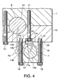
- FIG. 4 is a schematic front view of the crankshaft bearing cap and the control shaft bearing cap, showing a loading condition.
- FIG. 5 is a perspective view of the crankshaft bearing cap and the control shaft bearing cap in an inverted state.
- FIGs. 6A and 6B are similar to FIGs. 2A and 2B but showing a variation with respect to the composition of the control shaft bearing cap.
- FIG. 7 is a schematic front view of a variation of the crankshaft bearing cap and the control shaft bearing cap that is preferable for mitigating loads acting on the control shaft.
- FIG. 8 is a front view of the control shaft and a connecting pin, showing preferable relative positions thereof.
- a double-link type variable-compression-ratio internal combustion engine to which this invention is applied comprises a cylinder block 1.
- a cylinder is formed in the cylinder block 1 and a piston 2 is enclosed in the cylinder so as to slide axially within the cylinder.
- An end of an upper link 3 is connected to the piston 2 via a piston pin 2a.
- Another end of the upper link 3 connected to a lower link 4 via a connecting pin 9.
- the lower link 4 is connected to a crankshaft 6 via a crankpin 11.
- the stroke range of the piston 2 within the cylinder varies depending on an angle subtended by the piston pin 2a and the crankpin 11 at the connecting pin 9.
- a control link 5 is connected to the lower link 4 via a connecting pin 10.
- the connecting pin 10 connects an end of the control link 5 to the lower link 4 on the opposite side of the crankpin 11 to the connecting pin 9.
- Another end of the control link 5 is connected to a control shaft 7 via a connecting pin 12.
- the crankshaft 6 and the control shaft 7 have rotation axes which extend in parallel with each other.
- the connecting pin 12 connects the control link 5 to the control shaft 7 at a point eccentric with a rotation axis of the control shaft 7.
- the control shaft 7 performs a rotational displacement according to an operation of an actuator 8 constituted by an electric motor.
- the lower link 4 When the control shaft 7 performs a rotational displacement, the lower link 4 performs a rotational displacement about the crankpin 11 via the control link 5 which is connected to the control shaft 7 at a point eccentric with the rotation axis, and the angle subtended by the piston pin 2a and the crankpin 11 at the connecting pin 9 varies. When this angle varies, the stroke range of the piston 2 shifts. The shift of the stroke range of the piston 2 results in a variation in the compression ratio of the internal combustion engine.
- the internal combustion engine operates at a low compression ratio in a high-load operation region irrespective of the engine rotation speed so as to prevent knock from occurring while operating at a high compression ratio in a low-to-middle-load operation region where knock is unlikely to occur so as to increase an output power.
- the bearing structure according to this invention relates to a bearing for the crankshaft 6 and a bearing for the control shaft 7 of the internal combustion engine constructed as described above.
- a main journal of the crankshaft 6 is supported by a bearing installed in a circular bearing bore which is constituted by a semi-circular cutout 13a formed in a crankshaft bearing cap 13 and a semi-circular cutout 1a formed in the cylinder block 1.
- the control shaft 7 is supported by a bearing installed in a circular bearing bore constituted by a circular cutout 14a which is formed in a control shaft bearing cap 14. This figure represents a state where the bearing caps 13, 14 are viewed from the front of the engine.
- the crankshaft bearing cap 13 is fixed to the cylinder block 1 using joint bolts 15 and 17.
- the control shaft bearing cap 14 is fixed to the crankshaft bearing cap 13 using joint bolts 16 and 18.
- the joint bolts 15 and 17 are referred to as a first pair of joint bolts and the joint bolts 16 are 18 are referred to as a second pair of joint bolts.
- the first pair of joint bolts 15 and 17 penetrate through-holes formed in the crankshaft bearing cap 13 on both sides of the cutout 13a from below, and are screwed into bolt holes formed in the cylinder block 1 on both sides of the cutout 1a.
- the second pair of joint bolts 16 and 18 penetrate through-holes formed in the control shaft bearing cap 14 on both sides of the cutout 14a from below, and are screwed into bolt holes formed in the crankshaft bearing cap 13 on both sides of the joint bolt 17.
- the joint bolt 17 is disposed such that an axis of the joint bolt 17 intersects with the control shaft 7.
- the joint bolt 16 is located between the axes of the joint bolt 15 and the joint bolt 17, and the joint bolt 17 is located between the axes of the joint bolt 16 and the joint bolt 18.
- the joint bolt 17 is located nearer to the control shaft 7 than the joint bolt 15, and the joint bolt 18 is located further from the crankshaft 6 than the joint bolt 16.
- the joint bolt 17 is referred to as a first joint bolt and the joint bolt 18 is referred to as a second joint bolt in the following description.
- crankshaft bearing cap 13 and the control shaft bearing cap 14 are located in an identical location along the axis of the crankshaft 6. In other words, the crankshaft bearing cap 13 and the control shaft bearing cap 14 are disposed on an identical vertical plane which is orthogonal to the axis of the crankshaft 6.
- a first countersink 13b is formed in a bottom surface of the crankshaft bearing cap 13 in advance so as to accommodate a bolt head 17a of the first joint bolt 17.
- a second countersink 14b is also formed in advance in a corresponding part in a top surface of the control shaft bearing cap 14.
- a positioning member 19 is embedded in the first countersink 13b.
- the positioning member 19 projects downward from the first countersink 13b and is inserted into the second countersink 14b when the control shaft bearing cap 14 is fixed to the crankshaft bearing cap 13.
- the positioning member 19 is preferably formed from a cylindrical member having an inner diameter that does not interfere with the bolt head 17a of the first joint bolt 17, but a cylindrical member having an inner diameter smaller than the diameter of the bolt head 17a or a solid columnar member may also be used as long as a sufficient fitting length between the positioning member 19 and the first countersink 13b is assured.
- a cylindrical positioning member 20 is embedded in a bolt hole formed in the crankshaft bearing cap 13 for the second joint bolt 18.
- an enlarged diameter part is formed in advance in the bolt hole formed in the crankshaft bearing cap 13 for the second joint bolt 18, and the positioning member 20 is embedded therein.
- a similar enlarged diameter part is formed in a bolt hole formed in the control shaft bearing cap 14 for the second joint bolt 18.
- the positioning member 20 projects downward from the crankshaft bearing cap 13, and is inserted into the enlarged diameter part of the bolt hole formed in the control shaft bearing cap 14 for the second joint bolt 18 when the control shaft bearing cap 14 is fixed to the crankshaft bearing cap 13.
- Positioning is thus performed at two points using the two positioning members 19 and 20 when the control shaft bearing cap 14 is fixed to the crankshaft bearing cap 13, and as a result, relative positioning of the bearing for the crankshaft 6 and the bearing for the control shaft 7 can be performed with a high degree of precision.
- the second joint bolt 18 is screwed into the bolt hole formed in the crankshaft bearing cap 13 after penetrating the positioning member 20.
- An engagement length A between the second joint bolt 18 and the bolt hole of the crankshaft bearing cap 13 is determined such that the second joint bolt 18 exerts a sufficient tightening force on the control shaft bearing cap 14 with respect to the crankshaft bearing cap 13. Since there is no component that may interfere with the second joint bolt 18 in the crankshaft bearing cap 13 above the positioning member 20, the bolt hole can be formed at a sufficient length.
- the second countersink 14b formed in the control shaft bearing cap 14 is preferably made shallow.
- the center of the control shaft 7 can be disposed nearer to the crankshaft bearing cap 13. As a result, the vertical distance between the crankshaft 6 and the control shaft 7 can be decreased and the variable-compression-ratio internal combustion engine can be made more compact.
- An arrow Fcr in the figure denotes a load acting on the bearing for the crankshaft 6 when the combustion load of the internal combustion engine is exerted on the crankshaft 6.
- An arrow Fco in the figure denotes a load acting on the bearing for the control shaft 7 when the combustion load of the internal combustion engine is exerted on the crankshaft 6.
- a broken line arrow F1 denotes a component of the load Fcr exerted on the joint bolt 15.
- a broken line arrow F4 denotes a component of the load Fcr exerted on the first joint bolt 17.
- a broken line F2 denotes a component of the load Fco exerted on the joint bolt 16.
- a broken line arrow F3 denotes a component of the load Fco exerted on the second joint bolt 18.
- the direction of the load Fcr depends on the link geometry of the internal combustion engine.
- the load Fcr is assumed to act obliquely downward as shown in the figure.
- the direction of the load Fco depends on the link geometry and a set compression ratio, but approximated to act in an opposite direction to that of the load Fcr. i.e. in an obliquely upward direction in the figure.
- the load Fcr exerts a load F1 on the joint bolt 15 and a load F4 on the first joint bolt 17.
- the load Fco exerts a load F2 on the joint bolt 16 and a load F3 on the second joint bolt 18.
- the loads Fcr and Fco exert a moment on the first joint bolt 17. This moment exerts a shearing force on the first joint bolt 17 in the vicinity of the joint surfaces of the cylinder block 1 and the crankshaft bearing cap 13.
- a bolt should be used in a condition in which only tensile stress or compression stress is generated therein. It is not preferable to use a bolt under an action of a moment or a resultant shearing force in view of ensuring the strength and durability of the bolt.
- the layout of the bolts is determined such that an axis of the first joint bolt 17 is located between the joint bolt 16 and the second joint bolt 18. Accordingly, an arm length of the moment which the load Fco exerts on the first joint bolt 17 is short, and hence a moment and a shearing force acting on the first joint bolt 17 are suppressed to be small. Further, the loads F2 and F3 act on the crankshaft bearing cap 13 substantially in the opposite direction to the load F4. Since these loads are counterbalanced, an axial force exerted on the first joint bolt 17 is also small.
- the allowable stress of the first joint bolt 17 can be decreased.
- the diameter of the first joint bolt 17 can be made smaller or a lower class bolt in terms of strength may be applied as the first joint bolt 17 so as to reduce the manufacturing cost of the bearing structure.
- the moment acting on the first joint bolt 17 is kept small.
- the vertical component of the load Fco coincides with the axis of the joint bolt 17, and therefore, if the center of the control shaft 7 is located on the axis of the first joint bolt 17, the moment acting on the first joint bolt 17 is decreased further.
- the direction of the load Fco varies according to the compression ratio of the internal combustion engine. It is not possible to control the direction of the load Fco to direct the shearing force acting portion of the first joint bolt 17 permanently irrespective of the variation in the compression ratio. It is preferable to determine the location of the first joint bolt 17 with respect to the link geometry such that the load Fco directs the shearing force acting portion of the first joint bolt 17 at least in an operation condition of the internal combustion engine, in which a large combustion load is generated.
- crankshaft bearing cap 13 and the control shaft bearing cap 14 when the bearing structure of the crankshaft 6 and the control shaft 7 constructed as described above is applied to an in-line four-cylinder internal combustion engine will be described.
- crankshaft bearing caps 13 for the respective cylinders form a ladder beam shape bearing cap structure X by connecting both side ends of the crankshaft bearing caps 13 with a pair of walls 26, respectively.
- the pair of walls 26 connecting both side ends of the crankshaft bearing caps 13 form a skirt of the cylinder block 1.
- control shaft bearing caps 14 for the respective cylinders form a ladder beam-shaped bearing cap structure Y by connecting both side ends of the control shaft bearing caps 14 via girders 21, respectively.
- crankshaft bearing caps 13 and the control shaft bearing caps 14 are provided in the form of the ladder beam-shaped bearing cap structure X and the ladder beam-shaped bearing cap structure Y, it is possible to eliminate the positioning member 20 disposed around the second joint bolt 18. It is enough to provide at least two of the control shaft bearing caps 14 with the positioning members 19. When at least two of the control shaft bearing caps 14 are provided with the positioning members 19, positioning of the bearing for the crankshaft 6 and the bearing for the control shaft 7 can be performed.
- the shape and the location of the girder 21 connecting the control shaft bearing caps 14 are not limited to those shown in FIG. 5 . They can be determined according to the distribution of stresses and the layout of the related members.
- a radius of the control shaft 7 is r1
- a radius of the connecting pin 12 connecting the control link 5 to the control shaft 7 is r2
- an eccentric distance of the center of the connecting pin 12 from the center of the control shaft 7 is d. It is preferable to determine the sizes of the control link 5, the control shaft 7, and the connecting pin 12 such that the following relation (1) is satisfied.
- the outer periphery of the connecting pin 12 does not protrude to the outside from the outer periphery of the control shaft 7 in a state where the control shaft 7 is viewed from an axial direction.
- the control shaft 7 can be inserted into the plural cutouts 14a sequentially from the front side or rear side of the internal combustion engine in a state where the ladder beam bearing cap structure Y is tentatively fixed to the bottom surface of the ladder beam-shaped bearing cap structure X.
- the supporting rigidity of the control shaft 7 is enhanced.
- deformation of the control shaft 7 is suppressed.
- the weight of the control shaft can be decreased, thereby decreasing a moment of inertia acting on the control shaft 7 about the rotation axis of the control shaft 7.
- a decrease in the moment of inertia brings about a decrease in the load of the actuator 8, and therefore a preferable effect is expected in terms of a reduction in the energy consumed by the actuator 8 and an improvement in the operation response of the control shaft 7.
- control shaft bearing cap 14 is divided into an upper member 22 and a lower member 23.
- a positioning member 24 is embedded in the bolt hole for the joint bolt 16 across the joint surfaces of the upper member 22 and the lower member 23, and a positioning member 25 is embedded in the bolt hole for the second joint bolt 18 across the joint surfaces of the upper member 22 and the lower member 23.
- control shaft 7 is first fitted into a cutout 22a of the upper member 22 and then the lower member 23 is fixed to the upper member 22 using the joint bolts 16 and 18 such that the control shaft 7 is supported by the cutout 22a and a cutout 23a.
- stud bolts may be embedded into the cylinder block 1 so as to project downward from the bottom surface. These stud bolts penetrate the crankshaft bearing cap 13 and nuts are tightened onto the penetrating end of the stud bolts.
- stud bolts may be embedded into the crankshaft bearing cap 13 so as to project downward from the bottom surface. These stud bolts penetrate the upper member 22 and the lower member 23 of the control shaft bearing cap 14 and nuts are tightened onto the penetrating end of the stud bolts.
- crankshaft bearing cap 13 and the control shaft bearing cap 14 are disposed on an identical vertical plane. These bearing caps may be disposed in offset positions along the rotation axis of the crankshaft 6.
- the crankshaft bearing cap 13 is fixed to the cylinder block 1 using bolts
- the control shaft bearing cap 14 is fixed to either the crankshaft bearing cap 13 or the cylinder block 1 using other bolts.
- crankshaft bearing cap 13 and the control shaft bearing cap 14 By disposing the crankshaft bearing cap 13 and the control shaft bearing cap 14 in offset positions along the rotation axis of the crankshaft 6, the bolts can penetrate both side ends of the bearing caps without restriction. According to this arrangement, deformation of the crankshaft bearing cap 13 and the resultant generation of a gap in the joint surfaces of the crankshaft bearing cap 13 and the control shaft bearing cap 14 due to the combustion load of the internal combustion engine do not occur.
- crankshaft bearing cap 13 and the control shaft bearing cap 14 are disposed in offset positions along the rotation axis of the crankshaft 6, the size of the crankshaft bearing cap 13 in the direction of the rotation axis of the crankshaft 6 must be increased so as to fix the control shaft bearing cap 14. Otherwise the size of the control shaft bearing cap 14 must be increased such that the control shaft bearing cap 14 contacts the cylinder block 1 directly. Accordingly, the length of the bolts used therefor must be increased. In either case, the bearing structure inevitably becomes large.
- crankshaft bearing cap 13 and the control shaft bearing cap 14 are disposed on an identical vertical plane and the first joint bolt 17 is located between the center axes of the second pair of the joint bolts 16, 18, the generation of a gap between the crankshaft bearing cap 13 and the cylinder block 1 can be prevented without causing the size of the bearing structure to become large, and the crankshaft 6 and control shaft 7 can be disposed in positions which are close in terms of a horizontal distance.
Abstract
An internal combustion engine varies a compression ratio according to a rotational displacement of a control shaft (7) which is connected to a crankshaft (6) via links (4, 5). A crankshaft bearing cap (13) supporting the crankshaft (6) in association with a cylinder block (1) is fixed to the cylinder block (1) by a first pair of joint bolts (15, 17). A control shaft bearing cap (14) which supports the control shaft (7) is fixed to the crankshaft bearing cap (13) by a second pair of joint bolts (16, 18). A first joint bolt (17) of the first pair of joint bolts (15, 17), which is nearer to the control shaft (7), is disposed between the axes of the second pair of joint bolts (16, 18). The supporting structure of the crankshaft (6) is thereby enhanced.
Description
- This invention relates to a bearing structure for a double-link type variable-compression-ratio internal combustion engine in which a piston and a crankshaft are connected via plural links.
-
JP2004-092448A - The double-link type internal combustion engine according to the prior art comprises a crankshaft bearing cap fixed to a cylinder block of the internal combustion engine and a control shaft bearing cap fixed to the crankshaft bearing cap. The crankshaft bearing cap and the control shaft bearing cap are located on an identical vertical plane.
- A semi-circular cutout is formed in the top surface of the crankshaft bearing cap. Another semi-circular cutout is formed in a bottom surface of the cylinder block of the internal combustion engine. The crankshaft penetrates a bearing bore having a circular cross-section formed by this pair of the semi-circular cutouts.
- A semi-circular cutout is formed in the top surface of the control shaft bearing cap. Another semi-circular cutout is formed in the bottom surface of the crankshaft bearing cap. The control shaft penetrates a bearing bore having a circular cross-section formed by this pair of the semi-circular cutouts.
- The control shaft bearing cap is fixed to the crankshaft bearing cap using two joint bolts which penetrate the control shaft bearing cap vertically on both sides of the control shaft. The two joint bolts also penetrate the crankshaft bearing cap and are secured to the cylinder block in the vicinity of the bearing surface formed in the cylinder block. Therefore, the two joint bolts also serve to fix the crankshaft bearing cap to the cylinder block.
- An extra bolt penetrates the crankshaft bearing cap on the opposite side of the crankshaft to the control shaft and is secured to the cylinder block.
- In a double-link type internal combustion engine, relative locations of the crankshaft, the control shaft, and the links (hereinafter referred to as link geometry) are not constant. In an internal combustion engine having a different piston stroke range or a different cylinder bore diameter, preferred link geometry for suppressing noise or oscillation generated in the internal combustion engine may also be different.
- In certain cases, link geometry which causes the crankshaft and the control shaft to become adjacent in a horizontal direction when viewed axially along the crankshaft is required. If such a requirement arises in the bearing structure according to the prior art, of the two joint bolts that secure the control shaft bearing cap to the crankshaft bearing cap, the joint bolt disposed between the crankshaft and the control shaft may interfere with the crankshaft. If this is the case, to avoid interference with the crankshaft, the joint bolt cannot be allowed to penetrate the crankshaft bearing cap. Accordingly, the crankshaft bearing cap is secured to the cylinder block by only two bolts, i.e. one of the pair of the joint bolts and the extra bolt. These bolts are located at both side ends of the crankshaft bearing cap.
- This structure causes a distance between the joint bolt located on the opposite side of the control shaft to the crankshaft and the extra bolt to increase such that the crankshaft bearing cap can be deformed easily when the internal combustion engine exerts a downward combustion load on the crankshaft. If the crankshaft bearing cap is deformed, a gap may be generated between the crankshaft bearing cap and the cylinder block.
- The generation of a gap results in an excessive internal stress in the components of the bearing structure. Further, joint surfaces of the crankshaft bearing cap and the cylinder block may suffer wear due to oscillation during stress, or in other words fretting wear.
- According to the fixing structure of the crankshaft bearing cap and the control shaft bearing cap according to the prior art, however, it is difficult to maintain close contact between the crankshaft bearing cap and the cylinder block against the downward load that the internal combustion engine exerts on the crankshaft.
- It is therefore an object of this invention to improve a fixing structure for fixing the crankshaft bearing cap to the cylinder block in a double-link type variable-compression-ratio internal combustion engine.
- In order to achieve the above object, this invention provides a bearing structure for an internal combustion engine, the engine comprising a cylinder block, a crankshaft, and a control shaft. The bearing structure comprises a cutout formed in the cylinder block, a crankshaft bearing cap having a cutout which functions as a bearing bore for the crankshaft in association with the cutout of the cylinder block, a first pair of joint bolts which fix the crankshaft bearing cap to the cylinder block, the first pair of joint bolts comprising a first joint bolt which is located nearer to the control shaft than another joint bolt of the first pair, a control shaft bearing cap which has a cutout functioning as a bearing bore for the control shaft, and a second pair of joint bolts which fix the control shaft bearing cap to the crankshaft bearing cap, wherein a center axis of the first joint bolt is located between center axes of the second pair of joint bolts.
- The details as well as other features and advantages of this invention are set forth in the remainder of the specification and are shown in the accompanying drawings.
-
FIG. 1 is a schematic longitudinal sectional view of a double-link type variable-compression-ratio internal combustion engine to which this invention is applied. -
FIGs. 2A and 2B are a schematic front view and a schematic side view of a crankshaft bearing cap and a control shaft bearing cap according to this invention. -
FIG. 3 is an enlarged schematic front view of the control shaft bearing cap, showing the construction thereof in detail. -
FIG. 4 is a schematic front view of the crankshaft bearing cap and the control shaft bearing cap, showing a loading condition. -
FIG. 5 is a perspective view of the crankshaft bearing cap and the control shaft bearing cap in an inverted state. -
FIGs. 6A and 6B are similar toFIGs. 2A and 2B but showing a variation with respect to the composition of the control shaft bearing cap. -
FIG. 7 is a schematic front view of a variation of the crankshaft bearing cap and the control shaft bearing cap that is preferable for mitigating loads acting on the control shaft. -
FIG. 8 is a front view of the control shaft and a connecting pin, showing preferable relative positions thereof. - Referring to
FIG. 1 of the drawings, a double-link type variable-compression-ratio internal combustion engine to which this invention is applied comprises acylinder block 1. A cylinder is formed in thecylinder block 1 and apiston 2 is enclosed in the cylinder so as to slide axially within the cylinder. An end of anupper link 3 is connected to thepiston 2 via apiston pin 2a. Another end of theupper link 3 connected to alower link 4 via a connectingpin 9. Thelower link 4 is connected to acrankshaft 6 via acrankpin 11. - According to the above construction, when the
piston 2 slides in the cylinder up and down in the figure, thecrankshaft 6 performs a rotational movement via theupper link 3 and thelower link 4. - The stroke range of the
piston 2 within the cylinder varies depending on an angle subtended by thepiston pin 2a and thecrankpin 11 at the connectingpin 9. - To vary this angle, an end of a
control link 5 is connected to thelower link 4 via a connectingpin 10. The connectingpin 10 connects an end of thecontrol link 5 to thelower link 4 on the opposite side of thecrankpin 11 to the connectingpin 9. Another end of thecontrol link 5 is connected to acontrol shaft 7 via a connectingpin 12. Thecrankshaft 6 and thecontrol shaft 7 have rotation axes which extend in parallel with each other. - The connecting
pin 12 connects thecontrol link 5 to thecontrol shaft 7 at a point eccentric with a rotation axis of thecontrol shaft 7. Thecontrol shaft 7 performs a rotational displacement according to an operation of anactuator 8 constituted by an electric motor. - When the
control shaft 7 performs a rotational displacement, thelower link 4 performs a rotational displacement about thecrankpin 11 via thecontrol link 5 which is connected to thecontrol shaft 7 at a point eccentric with the rotation axis, and the angle subtended by thepiston pin 2a and thecrankpin 11 at the connectingpin 9 varies. When this angle varies, the stroke range of thepiston 2 shifts. The shift of the stroke range of thepiston 2 results in a variation in the compression ratio of the internal combustion engine. - When the position of the connecting
pin 12 lowers relative to the rotation axis of thecontrol shaft 7 as a result of the rotational displacement of thecontrol shaft 7, the position of the connectingpin 10 also lowers and thelower link 4 performs a rotational displacement about thecrankpin 11 in a clockwise direction in the figure so as to push up the connectingpin 9. This action shifts the stroke range of thepiston 2 upward in the figure, thereby causing the compression ratio of the internal combustion engine to increase. - When the position of the connecting
pin 12 rises relative to the rotation axis of thecontrol shaft 7 as a result of the rotational displacement of thecontrol shaft 7, the position of the connectingpin 10 also rises and thelower link 4 performs a rotational displacement about thecrankpin 11 in an anti-clockwise direction in the figure so as to pull down the connectingpin 9. This action shifts the stroke range of thepiston 2 downward in the figure, thereby causing the compression ratio of the internal combustion engine to decrease. - The internal combustion engine operates at a low compression ratio in a high-load operation region irrespective of the engine rotation speed so as to prevent knock from occurring while operating at a high compression ratio in a low-to-middle-load operation region where knock is unlikely to occur so as to increase an output power.
- The bearing structure according to this invention relates to a bearing for the
crankshaft 6 and a bearing for thecontrol shaft 7 of the internal combustion engine constructed as described above. - Referring to
FIG. 2A , a main journal of thecrankshaft 6 is supported by a bearing installed in a circular bearing bore which is constituted by asemi-circular cutout 13a formed in acrankshaft bearing cap 13 and asemi-circular cutout 1a formed in thecylinder block 1. Thecontrol shaft 7 is supported by a bearing installed in a circular bearing bore constituted by acircular cutout 14a which is formed in a controlshaft bearing cap 14. This figure represents a state where the bearing caps 13, 14 are viewed from the front of the engine. - The
crankshaft bearing cap 13 is fixed to thecylinder block 1 usingjoint bolts shaft bearing cap 14 is fixed to thecrankshaft bearing cap 13 usingjoint bolts joint bolts joint bolts 16 are 18 are referred to as a second pair of joint bolts. - The first pair of
joint bolts crankshaft bearing cap 13 on both sides of thecutout 13a from below, and are screwed into bolt holes formed in thecylinder block 1 on both sides of thecutout 1a. - The second pair of
joint bolts shaft bearing cap 14 on both sides of thecutout 14a from below, and are screwed into bolt holes formed in thecrankshaft bearing cap 13 on both sides of thejoint bolt 17. Thejoint bolt 17 is disposed such that an axis of thejoint bolt 17 intersects with thecontrol shaft 7. - As a result, the
joint bolt 16 is located between the axes of thejoint bolt 15 and thejoint bolt 17, and thejoint bolt 17 is located between the axes of thejoint bolt 16 and thejoint bolt 18. In other words thejoint bolt 17 is located nearer to thecontrol shaft 7 than thejoint bolt 15, and thejoint bolt 18 is located further from thecrankshaft 6 than thejoint bolt 16. Thejoint bolt 17 is referred to as a first joint bolt and thejoint bolt 18 is referred to as a second joint bolt in the following description. - Referring to
FIG. 2B , thecrankshaft bearing cap 13 and the controlshaft bearing cap 14 are located in an identical location along the axis of thecrankshaft 6. In other words, thecrankshaft bearing cap 13 and the controlshaft bearing cap 14 are disposed on an identical vertical plane which is orthogonal to the axis of thecrankshaft 6. - Referring to
FIG. 3 , afirst countersink 13b is formed in a bottom surface of thecrankshaft bearing cap 13 in advance so as to accommodate abolt head 17a of the firstjoint bolt 17. Asecond countersink 14b is also formed in advance in a corresponding part in a top surface of the controlshaft bearing cap 14. - A positioning
member 19 is embedded in thefirst countersink 13b. The positioningmember 19 projects downward from thefirst countersink 13b and is inserted into thesecond countersink 14b when the controlshaft bearing cap 14 is fixed to thecrankshaft bearing cap 13. The positioningmember 19 is preferably formed from a cylindrical member having an inner diameter that does not interfere with thebolt head 17a of the firstjoint bolt 17, but a cylindrical member having an inner diameter smaller than the diameter of thebolt head 17a or a solid columnar member may also be used as long as a sufficient fitting length between the positioningmember 19 and thefirst countersink 13b is assured. - A
cylindrical positioning member 20 is embedded in a bolt hole formed in thecrankshaft bearing cap 13 for the secondjoint bolt 18. For this purpose, an enlarged diameter part is formed in advance in the bolt hole formed in thecrankshaft bearing cap 13 for the secondjoint bolt 18, and the positioningmember 20 is embedded therein. A similar enlarged diameter part is formed in a bolt hole formed in the controlshaft bearing cap 14 for the secondjoint bolt 18. The positioningmember 20 projects downward from thecrankshaft bearing cap 13, and is inserted into the enlarged diameter part of the bolt hole formed in the controlshaft bearing cap 14 for the secondjoint bolt 18 when the controlshaft bearing cap 14 is fixed to thecrankshaft bearing cap 13. - Positioning is thus performed at two points using the two
positioning members shaft bearing cap 14 is fixed to thecrankshaft bearing cap 13, and as a result, relative positioning of the bearing for thecrankshaft 6 and the bearing for thecontrol shaft 7 can be performed with a high degree of precision. - The second
joint bolt 18 is screwed into the bolt hole formed in thecrankshaft bearing cap 13 after penetrating the positioningmember 20. An engagement length A between the secondjoint bolt 18 and the bolt hole of thecrankshaft bearing cap 13 is determined such that the secondjoint bolt 18 exerts a sufficient tightening force on the controlshaft bearing cap 14 with respect to thecrankshaft bearing cap 13. Since there is no component that may interfere with the secondjoint bolt 18 in thecrankshaft bearing cap 13 above the positioningmember 20, the bolt hole can be formed at a sufficient length. - It is also possible to provide a similar positioning member in a bolt hole for the other
joint bolt 16 of the second pair of thejoint bolts crankshaft 6 is located in a position corresponding to an extension of thejoint bolt 16, it may be difficult to obtain a sufficient engagement length between thejoint bolt 16 and the corresponding bolt hole of thecrankshaft bearing cap 13 which is located above the positioning member. In other words, a covering depth C of thecrankshaft bearing cap 13 with respect to thecrankshaft 6 shown inFIG. 3 inevitably becomes too thin to ensure a sufficient engagement length between thejoint bolt 16 and the bolt hole. If the covering depth C is thin, this part suffers a concentration of stress caused by the combustion load of the internal combustion engine acting on the bearing for thecrankshaft 6. - It is therefore preferable to dispose the
positioning members joint bolts crankshaft 6. - It is also possible to cause the
bolt head 17a of the firstjoint bolt 17 to project into thesecond countersink 14b located on the control shaft side. However, to prevent strain from occurring in the controlshaft bearing cap 14 due to the combustion load of the internal combustion engine, which acts on the bearing for thecrankshaft 6, thesecond countersink 14b formed in the controlshaft bearing cap 14 is preferably made shallow. By ensuring that thebolt head 17a of the firstjoint bolt 17 does not project into thesecond countersink 14b but remain in thefirst countersink 13b of thecrankshaft bearing cap 13, thesecond countersink 14b can be made shallow to an extent that does not affect the positioning precision of the positioningmember 19. - By decreasing the depth of the
second countersink 14b, the center of thecontrol shaft 7 can be disposed nearer to thecrankshaft bearing cap 13. As a result, the vertical distance between thecrankshaft 6 and thecontrol shaft 7 can be decreased and the variable-compression-ratio internal combustion engine can be made more compact. - Referring to
FIG. 4 , the loads acting on thecrankshaft bearing cap 13, thecylinder block 1, and the controlshaft bearing cap 14 will be described. - An arrow Fcr in the figure denotes a load acting on the bearing for the
crankshaft 6 when the combustion load of the internal combustion engine is exerted on thecrankshaft 6. An arrow Fco in the figure denotes a load acting on the bearing for thecontrol shaft 7 when the combustion load of the internal combustion engine is exerted on thecrankshaft 6. A broken line arrow F1 denotes a component of the load Fcr exerted on thejoint bolt 15. A broken line arrow F4 denotes a component of the load Fcr exerted on the firstjoint bolt 17. A broken line F2 denotes a component of the load Fco exerted on thejoint bolt 16. A broken line arrow F3 denotes a component of the load Fco exerted on the secondjoint bolt 18. - The direction of the load Fcr depends on the link geometry of the internal combustion engine. Herein, the load Fcr is assumed to act obliquely downward as shown in the figure. The direction of the load Fco depends on the link geometry and a set compression ratio, but approximated to act in an opposite direction to that of the load Fcr. i.e. in an obliquely upward direction in the figure.
- The load Fcr exerts a load F1 on the
joint bolt 15 and a load F4 on the firstjoint bolt 17. The load Fco exerts a load F2 on thejoint bolt 16 and a load F3 on the secondjoint bolt 18. - The loads Fcr and Fco exert a moment on the first
joint bolt 17. This moment exerts a shearing force on the firstjoint bolt 17 in the vicinity of the joint surfaces of thecylinder block 1 and thecrankshaft bearing cap 13. - Generally, a bolt should be used in a condition in which only tensile stress or compression stress is generated therein. It is not preferable to use a bolt under an action of a moment or a resultant shearing force in view of ensuring the strength and durability of the bolt.
- According to thus bearing structure, the layout of the bolts is determined such that an axis of the first
joint bolt 17 is located between thejoint bolt 16 and the secondjoint bolt 18. Accordingly, an arm length of the moment which the load Fco exerts on the firstjoint bolt 17 is short, and hence a moment and a shearing force acting on the firstjoint bolt 17 are suppressed to be small. Further, the loads F2 and F3 act on thecrankshaft bearing cap 13 substantially in the opposite direction to the load F4. Since these loads are counterbalanced, an axial force exerted on the firstjoint bolt 17 is also small. - According to the above construction of the bearing structure, the allowable stress of the first
joint bolt 17 can be decreased. As a result, the diameter of the firstjoint bolt 17 can be made smaller or a lower class bolt in terms of strength may be applied as the firstjoint bolt 17 so as to reduce the manufacturing cost of the bearing structure. - Referring to
FIG. 7 , when the load Fco is directed toward the cross-sectional face of the firstjoint bolt 17 corresponding to the joint surfaces of thecylinder block 1 and the crankshaft bearing cap 13 (hereinafter referred to as a shearing force acting portion of the joint bolt 17), the moment acting on the firstjoint bolt 17 is kept small. The vertical component of the load Fco coincides with the axis of thejoint bolt 17, and therefore, if the center of thecontrol shaft 7 is located on the axis of the firstjoint bolt 17, the moment acting on the firstjoint bolt 17 is decreased further. - The direction of the load Fco varies according to the compression ratio of the internal combustion engine. It is not possible to control the direction of the load Fco to direct the shearing force acting portion of the first
joint bolt 17 permanently irrespective of the variation in the compression ratio. It is preferable to determine the location of the firstjoint bolt 17 with respect to the link geometry such that the load Fco directs the shearing force acting portion of the firstjoint bolt 17 at least in an operation condition of the internal combustion engine, in which a large combustion load is generated. - Referring to
FIG. 5 , a shape of thecrankshaft bearing cap 13 and the controlshaft bearing cap 14 when the bearing structure of thecrankshaft 6 and thecontrol shaft 7 constructed as described above is applied to an in-line four-cylinder internal combustion engine will be described. - The crankshaft bearing caps 13 for the respective cylinders form a ladder beam shape bearing cap structure X by connecting both side ends of the crankshaft bearing caps 13 with a pair of
walls 26, respectively. The pair ofwalls 26 connecting both side ends of the crankshaft bearing caps 13 form a skirt of thecylinder block 1. - The control shaft bearing caps 14 for the respective cylinders form a ladder beam-shaped bearing cap structure Y by connecting both side ends of the control shaft bearing caps 14 via
girders 21, respectively. - When the crankshaft bearing caps 13 and the control shaft bearing caps 14 are provided in the form of the ladder beam-shaped bearing cap structure X and the ladder beam-shaped bearing cap structure Y, it is possible to eliminate the positioning
member 20 disposed around the secondjoint bolt 18. It is enough to provide at least two of the control shaft bearing caps 14 with thepositioning members 19. When at least two of the control shaft bearing caps 14 are provided with thepositioning members 19, positioning of the bearing for thecrankshaft 6 and the bearing for thecontrol shaft 7 can be performed. - The shape and the location of the
girder 21 connecting the control shaft bearing caps 14 are not limited to those shown inFIG. 5 . They can be determined according to the distribution of stresses and the layout of the related members. - The ladder beam bearing cap structure Y constructed from the plural control shaft bearing caps 14 limits the shape of the
control shaft 7. - Referring to
FIG. 8 , it is assumed that a radius of thecontrol shaft 7 is r1, a radius of the connectingpin 12 connecting thecontrol link 5 to thecontrol shaft 7 is r2, and an eccentric distance of the center of the connectingpin 12 from the center of thecontrol shaft 7 is d. It is preferable to determine the sizes of thecontrol link 5, thecontrol shaft 7, and the connectingpin 12 such that the following relation (1) is satisfied. -

- When the relation (1) is satisfied, the outer periphery of the connecting
pin 12 does not protrude to the outside from the outer periphery of thecontrol shaft 7 in a state where thecontrol shaft 7 is viewed from an axial direction. When assembling the internal combustion engine, as long as this relation is satisfied, thecontrol shaft 7 can be inserted into theplural cutouts 14a sequentially from the front side or rear side of the internal combustion engine in a state where the ladder beam bearing cap structure Y is tentatively fixed to the bottom surface of the ladder beam-shaped bearing cap structure X. - As described above, by forming the ladder beam bearing cap structure Y by plural control shaft bearing caps 14, the supporting rigidity of the
control shaft 7 is enhanced. By thus enhancing the supporting rigidity of thecontrol shaft 7, deformation of thecontrol shaft 7 is suppressed. As a result, the weight of the control shaft can be decreased, thereby decreasing a moment of inertia acting on thecontrol shaft 7 about the rotation axis of thecontrol shaft 7. - A decrease in the moment of inertia brings about a decrease in the load of the
actuator 8, and therefore a preferable effect is expected in terms of a reduction in the energy consumed by theactuator 8 and an improvement in the operation response of thecontrol shaft 7. - Referring to
FIGs. 6A and 6B , a variation with respect to the construction of the controlshaft bearing cap 14 will be described. - Herein, the control
shaft bearing cap 14 is divided into anupper member 22 and alower member 23. - When the control
shaft bearing cap 14 is divided, positioning of thelower member 23 with respect to theupper member 22 is required. For this purpose, a positioningmember 24 is embedded in the bolt hole for thejoint bolt 16 across the joint surfaces of theupper member 22 and thelower member 23, and a positioningmember 25 is embedded in the bolt hole for the secondjoint bolt 18 across the joint surfaces of theupper member 22 and thelower member 23. - hen the internal combustion engine is assembled, the
control shaft 7 is first fitted into acutout 22a of theupper member 22 and then thelower member 23 is fixed to theupper member 22 using thejoint bolts control shaft 7 is supported by thecutout 22a and acutout 23a. - By thus dividing the control
shaft bearing cap 14, the limitation with respect to the radius r1 of thecontrol shaft 7, the radius r2 and the eccentric distance d of the connectingpin 12, which is represented by the relation (1), can be relaxed such that thecontrol shaft 7 can be fitted into the controlshaft bearing cap 14 easily. - Instead of using the
joint bolts cylinder block 1 so as to project downward from the bottom surface. These stud bolts penetrate thecrankshaft bearing cap 13 and nuts are tightened onto the penetrating end of the stud bolts. Similarly, instead of using thejoint bolts crankshaft bearing cap 13 so as to project downward from the bottom surface. These stud bolts penetrate theupper member 22 and thelower member 23 of the controlshaft bearing cap 14 and nuts are tightened onto the penetrating end of the stud bolts. - As can be seen in
FIG. 2B andFIG. 6B , in the embodiment described above, thecrankshaft bearing cap 13 and the controlshaft bearing cap 14 are disposed on an identical vertical plane. These bearing caps may be disposed in offset positions along the rotation axis of thecrankshaft 6. In this case, thecrankshaft bearing cap 13 is fixed to thecylinder block 1 using bolts whereas the controlshaft bearing cap 14 is fixed to either thecrankshaft bearing cap 13 or thecylinder block 1 using other bolts. - By disposing the
crankshaft bearing cap 13 and the controlshaft bearing cap 14 in offset positions along the rotation axis of thecrankshaft 6, the bolts can penetrate both side ends of the bearing caps without restriction. According to this arrangement, deformation of thecrankshaft bearing cap 13 and the resultant generation of a gap in the joint surfaces of thecrankshaft bearing cap 13 and the controlshaft bearing cap 14 due to the combustion load of the internal combustion engine do not occur. - However, when the
crankshaft bearing cap 13 and the controlshaft bearing cap 14 are disposed in offset positions along the rotation axis of thecrankshaft 6, the size of thecrankshaft bearing cap 13 in the direction of the rotation axis of thecrankshaft 6 must be increased so as to fix the controlshaft bearing cap 14. Otherwise the size of the controlshaft bearing cap 14 must be increased such that the controlshaft bearing cap 14 contacts thecylinder block 1 directly. Accordingly, the length of the bolts used therefor must be increased. In either case, the bearing structure inevitably becomes large. - In the bearing structure according to this invention, since the
crankshaft bearing cap 13 and the controlshaft bearing cap 14 are disposed on an identical vertical plane and the firstjoint bolt 17 is located between the center axes of the second pair of thejoint bolts crankshaft bearing cap 13 and thecylinder block 1 can be prevented without causing the size of the bearing structure to become large, and thecrankshaft 6 and controlshaft 7 can be disposed in positions which are close in terms of a horizontal distance. - The contents of Tokugan
2007-209538 - Although the invention has been described above with reference to certain embodiments, the invention is not limited to the embodiments described above. Modifications and variations of the embodiments described above will occur to those skilled in the art, within the scope of the claims.
- The embodiments of this invention in which an exclusive property or privilege is claimed are defined as follows:
Claims (11)
- A bearing structure for an internal combustion engine, the engine comprising a cylinder block (1), a crankshaft (6), and a control shaft (7) which is disposed in parallel with the crank shaft (6) and varies a compression ratio of the engine, comprising:a cutout (13a) formed in the cylinder block (1);a crankshaft bearing cap (13) having a cutout (13a) which functions as a bearing bore for the crankshaft (6) in association with the cutout (1a) of the cylinder block (1); anda pair of joint bolts (15, 17) which fix the crankshaft bearing cap (13) to the cylinder block (1), the pair of joint bolts (15, 17) comprising a first joint bolt (17) which has a center axis intersecting with the control shaft (7).
- The bearing structure as defined in Claim 1, further comprising a control shaft bearing cap (14) which has a cutout (14a) functioning as a bearing bore for the control shaft (7), and a second pair of joint bolts (16, 18) which fix the control shaft bearing cap (14) to the crankshaft bearing cap (13) in a state where the center axis of the first joint bolt (17) is located between center axes of the second pair of joint bolts (16, 18).
- The bearing structure as defined in Claim 2, wherein the first joint bolt (17) comprises a bolt head (17a), the crankshaft bearing cap (13) and the control shaft bearing cap (14) respectively comprise joint surfaces which are in contact with each other, and the crankshaft bearing cap (13) comprises a first countersink (13b) formed in the joint surface thereof for accommodating the bolt head (17a).
- The bearing structure as defined in Claim 2 or Claim 3, wherein the control shaft bearing cap (14) comprises a second countersink (14b) formed in the joint surface thereof and facing the first countersink (13b), and the bearing structure further comprises a first positioning member (19) which is fitted into the first countersink (13b) and the second countersink (14b).
- The bearing structure as defined in Claim 4, wherein the control shaft bearing cap (14) comprises a pair of through-holes which the second pair of joint bolts (16, 18) penetrate, the crankshaft bearing cap (13) comprises a pair of bolt holes into which the second pair of joint bolts (16, 18) penetrating the pair of through-holes are screwed, the second pair of joint bolts (16, 18) comprises a second joint bolt (18) which is located further from the crankshaft (6) than another joint bolt (16) of the second pair of joint bolts (16, 18), and the bearing structure further comprises a second positioning member (20) which is fitted into the through-hole and the bolt hole for the second joint bolt (18), wherein the second joint bolt (18) penetrates the second positioning member (20).
- The bearing structure as defined in any one of Claim 2 through Claim 5, wherein the internal combustion engine further comprises a piston (2), an upper link (3) connected to the piston (2), a lower link (4) connected to the crankshaft (6) via a crankpin (11), and a control link (5) connected to the control shaft (7) via a connecting pin (12) which is offset from a rotation axis of the control shaft (7), wherein the upper link (3) and the control link (5) are connected to the lower link (4) in different positions to the crank pin (11), the cylinder block (1) and the crankshaft bearing cap (13) respectively comprise joint surfaces which are in contact with each other, and the first joint bolt (17) is located in a position in which a line representing an acting direction of a combustion load (Fco) of the internal combustion engine on the control shaft (7), which is transferred from the upper link (3) via the lower link (4) and the control link (5), intersects a cross-section of the first joint bolt (17) corresponding to the joint surfaces of the cylinder block (1) and the crankshaft bearing cap (13).
- The bearing structure as defined in any one of Claim 6, wherein the control shaft bearing cap (14) is formed from a single plate, and a radius (r1) of the control shaft (7) is set to be equal to or greater than a sum of a distance (d) between a center of the connecting pin (12) and the rotation axis of the control shaft (7) and a radius (r2) of the connecting pin (12).
- The bearing structure as defined in any one of Claim 2 through Clam 7, wherein the cylinder block (1) comprises a plurality of cylinders, and the bearing structure comprises a first ladder beam structure (Y) comprising a plurality of control shaft bearing caps (14) which are disposed intermittently along a rotation axis of the crankshaft (6) and girders (21) which connect both side ends of the respective control shaft bearing caps (14) in an axial direction of the crankshaft (6).
- The bearing structure as defined in Claim 8, wherein the cylinder block (1) further comprises a pair of walls (26) which form a skirt of the internal combustion engine, and the bearing structure comprises a second ladder beam structure (X) comprising a plurality of crankshaft bearing caps (13) disposed intermittently along the rotation axis of the crankshaft (6), wherein both side ends of the respective crankshaft bearing caps (13) are fixed to the pair of walls (26).
- The bearing structure as defined in any one of Claim 2 through Claim 9, wherein the crankshaft bearing cap (13) and the control shaft bearing cap (14) are disposed on an identical plain which is perpendicular to a rotation axis of the crankshaft (6).
- The bearing structure as defined in any one of Claim 1 through Claim 10, wherein the center axis of the First joint bolt (17) passes through a center of the control shaft (7).
Applications Claiming Priority (1)
| Application Number | Priority Date | Filing Date | Title |
|---|---|---|---|
| JP2007209538A JP2009041512A (en) | 2007-08-10 | 2007-08-10 | Bearing structure of double-link type internal combustion engine |
Publications (1)
| Publication Number | Publication Date |
|---|---|
| EP2022958A2 true EP2022958A2 (en) | 2009-02-11 |
Family
ID=39926555
Family Applications (1)
| Application Number | Title | Priority Date | Filing Date |
|---|---|---|---|
| EP08013186A Withdrawn EP2022958A2 (en) | 2007-08-10 | 2008-07-22 | Bearing structure for variable-compression-radio internal combustion engine |
Country Status (3)
| Country | Link |
|---|---|
| US (1) | US20090041398A1 (en) |
| EP (1) | EP2022958A2 (en) |
| JP (1) | JP2009041512A (en) |
Cited By (5)
| Publication number | Priority date | Publication date | Assignee | Title |
|---|---|---|---|---|
| EP2063085A1 (en) * | 2006-09-12 | 2009-05-27 | Honda Motor Co., Ltd | Engine with variable stroke characteristics |
| KR101114378B1 (en) * | 2009-10-06 | 2012-02-15 | 현대자동차주식회사 | Variable compression ratio device |
| DE102011116609A1 (en) * | 2011-10-21 | 2013-04-25 | Audi Ag | Multi-joint crank drive of internal combustion engine, has coupling lever and cover portion together forming a bearing seat for crankshaft, connected mutually by screw connections whose longitudinal axes intersect/skew with each other |
| DE102011116952A1 (en) * | 2011-10-26 | 2013-05-02 | Audi Ag | Multi-joint crank drive of an internal combustion engine and method for operating a multi-joint crank drive |
| CN103154538A (en) * | 2010-12-27 | 2013-06-12 | 日产自动车株式会社 | Bearing cap and bearing cap composite |
Families Citing this family (7)
| Publication number | Priority date | Publication date | Assignee | Title |
|---|---|---|---|---|
| US8833328B2 (en) | 2010-12-29 | 2014-09-16 | Ford Global Technologies, Llc | Structural frame |
| KR101855525B1 (en) | 2011-01-31 | 2018-06-08 | 제이엔씨 주식회사 | Polymerizable liquid crystal composition and optical anisotropic body |
| US8887703B2 (en) | 2011-10-10 | 2014-11-18 | Ford Global Technologies, Llc | Integrated positive crankcase ventilation vent |
| EP2985442B1 (en) * | 2013-04-11 | 2018-05-23 | Nissan Motor Company, Limited | Internal combustion engine |
| RU2642956C1 (en) * | 2014-09-02 | 2018-01-29 | Ниссан Мотор Ко., Лтд. | Internal combustion engine with variable compression ratio |
| US10690048B2 (en) * | 2015-09-16 | 2020-06-23 | Nissan Motor Co., Ltd. | Bolt fastening method for lower link |
| KR102406127B1 (en) * | 2017-10-16 | 2022-06-07 | 현대자동차 주식회사 | Variable compression ratio engine |
Citations (2)
| Publication number | Priority date | Publication date | Assignee | Title |
|---|---|---|---|---|
| JP2004092448A (en) | 2002-08-30 | 2004-03-25 | Nissan Motor Co Ltd | Reciprocating variable compression ratio internal combustion engine |
| JP2007209538A (en) | 2006-02-09 | 2007-08-23 | Ziosoft Inc | Image processing method and program |
Family Cites Families (3)
| Publication number | Priority date | Publication date | Assignee | Title |
|---|---|---|---|---|
| JP3945419B2 (en) * | 2003-02-24 | 2007-07-18 | 日産自動車株式会社 | Reciprocating variable compression ratio engine |
| JP4736778B2 (en) * | 2005-12-16 | 2011-07-27 | 日産自動車株式会社 | Internal combustion engine and crank bearing structure thereof |
| JP4984574B2 (en) * | 2006-03-03 | 2012-07-25 | 日産自動車株式会社 | Crankshaft of piston crank mechanism |
-
2007
- 2007-08-10 JP JP2007209538A patent/JP2009041512A/en active Pending
-
2008
- 2008-07-22 US US12/177,585 patent/US20090041398A1/en not_active Abandoned
- 2008-07-22 EP EP08013186A patent/EP2022958A2/en not_active Withdrawn
Patent Citations (2)
| Publication number | Priority date | Publication date | Assignee | Title |
|---|---|---|---|---|
| JP2004092448A (en) | 2002-08-30 | 2004-03-25 | Nissan Motor Co Ltd | Reciprocating variable compression ratio internal combustion engine |
| JP2007209538A (en) | 2006-02-09 | 2007-08-23 | Ziosoft Inc | Image processing method and program |
Cited By (10)
| Publication number | Priority date | Publication date | Assignee | Title |
|---|---|---|---|---|
| EP2063085A1 (en) * | 2006-09-12 | 2009-05-27 | Honda Motor Co., Ltd | Engine with variable stroke characteristics |
| EP2063085A4 (en) * | 2006-09-12 | 2009-08-26 | Honda Motor Co Ltd | Engine with variable stroke characteristics |
| US8015955B2 (en) | 2006-09-12 | 2011-09-13 | Honda Motor Co., Ltd. | Variable stroke |
| KR101114378B1 (en) * | 2009-10-06 | 2012-02-15 | 현대자동차주식회사 | Variable compression ratio device |
| CN103154538A (en) * | 2010-12-27 | 2013-06-12 | 日产自动车株式会社 | Bearing cap and bearing cap composite |
| CN103154538B (en) * | 2010-12-27 | 2016-05-11 | 日产自动车株式会社 | Bearing cap and bearing cap complex |
| DE102011116609A1 (en) * | 2011-10-21 | 2013-04-25 | Audi Ag | Multi-joint crank drive of internal combustion engine, has coupling lever and cover portion together forming a bearing seat for crankshaft, connected mutually by screw connections whose longitudinal axes intersect/skew with each other |
| DE102011116609B4 (en) * | 2011-10-21 | 2015-02-19 | Audi Ag | Multi-joint crank drive |
| DE102011116952A1 (en) * | 2011-10-26 | 2013-05-02 | Audi Ag | Multi-joint crank drive of an internal combustion engine and method for operating a multi-joint crank drive |
| DE102011116952B4 (en) * | 2011-10-26 | 2015-09-03 | Audi Ag | Multi-joint crank drive of an internal combustion engine and method for operating a multi-joint crank drive |
Also Published As
| Publication number | Publication date |
|---|---|
| JP2009041512A (en) | 2009-02-26 |
| US20090041398A1 (en) | 2009-02-12 |
Similar Documents
| Publication | Publication Date | Title |
|---|---|---|
| EP2022958A2 (en) | Bearing structure for variable-compression-radio internal combustion engine | |
| EP1835146B1 (en) | Piston crank mechanism | |
| EP2119899A1 (en) | Bearing structure for crankshaft | |
| EP2660485A1 (en) | Bearing cap and bearing cap composite | |
| JP2007162637A (en) | Internal combustion engine and its crank bearing structure | |
| US9670872B2 (en) | Supporting structure for internal combustion engine | |
| EP3181925B1 (en) | Bearing structure | |
| JP2014095470A (en) | Crank shaft, bearing assembly, and large multi-cylinder two-stroke diesel engine | |
| JP4506340B2 (en) | Lower link in piston crank mechanism of internal combustion engine | |
| JP2004124776A (en) | Variable compression ratio mechanism and link parts for internal combustion engine | |
| US7273030B2 (en) | Crankshaft support structure of internal combustion engine | |
| JP2006177272A (en) | Lower link in piston crank mechanism of internal combustion engine | |
| US10690015B2 (en) | Cylinder head structure for internal combustion engine and internal combustion engine | |
| EP1808607B1 (en) | Journal bearing structure for crankshaft | |
| US11199156B2 (en) | Bearing cap, internal combustion engine, and manufacturing method of internal combustion engine | |
| CN109072813B (en) | Cylinder block and internal combustion engine with same | |
| JP4595817B2 (en) | Internal combustion engine | |
| KR102297189B1 (en) | Cylinder block for engine | |
| JPH11280752A (en) | Bearing structure of crank shaft | |
| EP3620640A1 (en) | Cylinder block assembly | |
| EP3763925A1 (en) | Variable-compression-ratio internal combustion engine | |
| JP2015117629A (en) | Engine | |
| JP3460296B2 (en) | Connecting rod | |
| KR20090124610A (en) | A connecting rod bearing for a vehicle's engine | |
| JP2010138873A (en) | Multi-cylinder internal combustion engine of variable compression ratio mechanism |
Legal Events
| Date | Code | Title | Description |
|---|---|---|---|
| PUAI | Public reference made under article 153(3) epc to a published international application that has entered the european phase |
Free format text: ORIGINAL CODE: 0009012 |
|
| 17P | Request for examination filed |
Effective date: 20080722 |
|
| AK | Designated contracting states |
Kind code of ref document: A2 Designated state(s): AT BE BG CH CY CZ DE DK EE ES FI FR GB GR HR HU IE IS IT LI LT LU LV MC MT NL NO PL PT RO SE SI SK TR |
|
| AX | Request for extension of the european patent |
Extension state: AL BA MK RS |
|
| STAA | Information on the status of an ep patent application or granted ep patent |
Free format text: STATUS: THE APPLICATION HAS BEEN WITHDRAWN |
|
| 18W | Application withdrawn |
Effective date: 20100218 |