EP2022679B1 - Front or rear block of an automobile - Google Patents
Front or rear block of an automobile Download PDFInfo
- Publication number
- EP2022679B1 EP2022679B1 EP20080161182 EP08161182A EP2022679B1 EP 2022679 B1 EP2022679 B1 EP 2022679B1 EP 20080161182 EP20080161182 EP 20080161182 EP 08161182 A EP08161182 A EP 08161182A EP 2022679 B1 EP2022679 B1 EP 2022679B1
- Authority
- EP
- European Patent Office
- Prior art keywords
- electrical
- vehicle
- electrical components
- wiring harness
- rear end
- Prior art date
- Legal status (The legal status is an assumption and is not a legal conclusion. Google has not performed a legal analysis and makes no representation as to the accuracy of the status listed.)
- Expired - Fee Related
Links
Images

Classifications
-
- B—PERFORMING OPERATIONS; TRANSPORTING
- B60—VEHICLES IN GENERAL
- B60R—VEHICLES, VEHICLE FITTINGS, OR VEHICLE PARTS, NOT OTHERWISE PROVIDED FOR
- B60R16/00—Electric or fluid circuits specially adapted for vehicles and not otherwise provided for; Arrangement of elements of electric or fluid circuits specially adapted for vehicles and not otherwise provided for
- B60R16/02—Electric or fluid circuits specially adapted for vehicles and not otherwise provided for; Arrangement of elements of electric or fluid circuits specially adapted for vehicles and not otherwise provided for electric constitutive elements
- B60R16/03—Electric or fluid circuits specially adapted for vehicles and not otherwise provided for; Arrangement of elements of electric or fluid circuits specially adapted for vehicles and not otherwise provided for electric constitutive elements for supply of electrical power to vehicle subsystems or for
Definitions
- the present invention generally relates to power supply networks and / or control of motor vehicles.
- the invention relates to a front or rear block of a motor vehicle, according to the preamble of claim 1.
- US 4,122,357 discloses a front or rear block according to the preamble of claim 1, comprising a motor vehicle electrical network in which the components at the front of the vehicle are connected by a beam to a single connection means.
- EP-A-0 714 812 describes a vehicle subdivided into several zones.
- the front zone has two beams interconnected by an intermediate beam.
- Each beam is electrically connected to the vehicle network by a connector.
- the interface between the front area and the rest of the vehicle is complex, both for the mounting and for the operation of the power supply network and / or control of the vehicle.
- the invention aims to provide a front or rear block whose integration with the electrical network and / or control of the vehicle is easier, and the operation of all electrical components is preserved, even when the beam is cut in one point.
- the invention relates to a front or rear block according to claim 1.
- the motor vehicle 1 represented on the figure 1 comprises, inter alia, a rigid carrier structure 2 and a front block 4 attached in one piece to the supporting structure 2.
- the carrying structure 2 comprises in particular longitudinally extending longitudinal members 6, one on the right and the other on the left of the vehicle.
- the front block 4 is rigidly fixed to the front ends of the longitudinal members 6.
- the front block 4 is here symbolized by a trapezoid drawn in dotted lines.
- the front block 4 typically comprises a rigid frame (not shown), and a plurality of equipment rigidly fixed to the frame.
- Such equipment may include, but is not limited to, the radiator, condenser, shock absorbers, a vehicle hood lock, projector washers, vehicle piping, and one or more of the following electrical components: a power train; fan 10 adapted to create a forced convection of air in contact with the radiator, the front headlamps 12, one or more available space sensors 14, one or more parking sensors 16, an ambient temperature sensor 18, a radar 20 able to detect the obstacles at the front of the vehicle, fog lights 22, a horn 24, movable flaps 26 movable to manage the ventilation of the passenger compartment of the vehicle, one or more pumps 28 provided for projecting a cleaning liquid from the outer ice of the headlamps, a speed sensor 30 forming part of the vehicle speed control device (cruise control), airbag sensors 32, etc.
- the front block also comprises a power supply and control beam 34 of the electrical components listed above.
- All the above equipment is generally mounted on the frame of the front block in the workshop of the supplier of the block, then the front block with pre-assembled equipment is attached to the front of the vehicle on the structure thereof.
- the beam 34 is mounted on the frame and connected to the various electrical components in the supplier's workshop, and then, once the front block is attached to the vehicle structure, the beam 34 is connected to the power supply network 36 and control of the vehicle.
- connection means 38 capable of electrically connecting the beam 34 to the network 36 at a single point of connection.
- the means 38 consist of an electrical connector comprising a male element 40 electrically connected to the vehicle network, and a female element 42, conjugated to the male element 40, electrically connected to the beam 34.
- the male element 40 of the connector comprises a plurality of male contacts, each connected to an electrical conductor of the network 36.
- These electrical conductors are either power supply conductors or control transfer conductors.
- the power supply conductors are connected to the power generators 44 of the vehicle, for example to the battery or the alternator.
- the control conductors carry analog or digital control information of the electrical components of the front block. They are connected to the various electronic control units 46, 48 of the vehicle.
- the female element 42 comprises a plurality of female contacts, each female contact being electrically in contact with one of the male contacts when the male element is engaged in the female element. Each female contact is also electrically connected to an electrical conductor of the beam 34.
- the beam 34 comprises a plurality of electrical power conductors, causing the electrical power from the connector 38 to the various electrical components.
- the beam 34 also includes control leads, transmitting control information to the electrical components. Some components, such as the horn 24, are connected only to power conductors. Other components, for example radar 20, are connected to both power conductors and control conductors.
- each control conductor of the beam 34 is electrically connected via a male contact and a female contact to a control conductor of the network 36.
- each power conductor of the beam 34 is connected by the intermediate of a male contact and a female contact to a power conductor of the network 36.
- the electrical connection of the beam 34 to the network 36 is extremely simple. Once the front block 4 is attached to the carrier structure of the vehicle, it suffices to engage the male element 40 of the electrical connector in the female element 42. Once the connection is made, each of the electrical components 10 to 32 is electrically connected. to the vehicle network.
- connection means 38 is an electronic box 50.
- the box 50 comprises means 52 for electrical supervision of the front block, and optionally, means 54 for analog / digital conversion and means 55 for multiplexing / demultiplexing.
- the means 56 identify the faulty components including by analyzing the evolution over time of the intensity and voltage of the current supplied to each component.
- the means 58 identify the failure in a predetermined list.
- This list can be common to all components, or be specific to each component. It can be partially common to all components.
- the list may include the following items: completely failed components, partially failed components, short circuit, overload, overvoltage, etc.
- certain electrical components of the front block are associated with electronic control units forming part of the electrical network of the vehicle 36.
- these components are the fan assembly 10, the space sensors 14, the sensors of the vehicle. parking aid 16, the radar 20, the flaps 26, the speed sensor 30, and the air bag sensors 32.
- Each of these components communicates with the corresponding control unit via the network 36 and the beam 34
- the electronic control unit manages the electrical components associated with it. Depending on the controls of the vehicle passengers, and the information available on the operation of the vehicle, the electronic control unit controls the commissioning, shutdown, or modification of the operation of the component, depending on the circumstances.
- the means 60 when they detect that such a component is faulty, communicate to the corresponding control unit, the identity of the component and the nature of the failure. In return, the control unit may return an order concerning this equipment, or any other component of the front block controlled by said control unit.
- the means 62 are capable of cutting off the power supply of each faulty electrical component.
- the means 62 receive from one of the vehicle's electrical control units a parameter representative of the state of the vehicle, specially developed for this purpose.
- this parameter indicates whether the vehicle is able to roll or not.
- the functions to be preserved are not the same depending on whether the vehicle is able to roll or is immobilized.
- the functions ensuring a good visibility to the driver (projectors) or contributing to the safety of the vehicle (airbag sensors, speed sensors for the automatic control of the speed of the vehicle , ...) are preserved.
- other functions can be cut off, such as the power supply of the pumps for cleaning the windows of the headlamps, the control of the ventilation flaps of the passenger compartment, etc.
- the means 62 will cut or not the power supply of each component. For this, the means 62 use predetermined decision trees.
- the network 36 comprises power conductors, control conductors dedicated to the transmission of analog control information, and control conductors dedicated to the transmission of digital control information.
- the various control conductors are electrically connected to the housing 50.
- the beam 34 comprises only power conductors, and analog control conductors.
- the analog control conductors of the network 36 are directly connected to the corresponding analog conductors of the beam 34.
- the digital control conductors of the network 36 are connected to the digital / analog conversion means 54, these means being able to convert the digital control signals received from the digital control conductors of the network 36 into analog control signals broadcast on the analog control conductors of the beam 34.
- the housing 50 sends the information relating to the faulty components to the electronic units of FIG. corresponding control either in the form of analogue information or in the form of digital information, as appropriate. If this information is sent in digital form, it is converted from analogue to digital by means 54.
- the digital information exchanged between the box 50 and the various electronic control units is exchanged in multiplexed form.
- the network 36 typically comprises only one digital input at the level of the housing 50.
- the housing 50 then comprises means 55 able to demultiplex the multiplexed digital signal received from the network 36, and to multiplex the digital signal broadcast on the network of the vehicle by the housing 50.
- control information is transmitted from the housing 50 to the various electrical components of the front block in analog form via the beam 34.
- the beam 34 may have different architectures.
- beam 34 has only one branch. All electrical components are connected successively, one after the other, on the beam 34 from the connection means 38.
- All equipment located downstream of the cutoff are more fueled.
- the beam 34 may also have a so-called T architecture, represented on the figure 1 .
- the beam 34 comprises a node 70, a common trunk 72 connecting the node 70 to the connection means 38, and two branches 74 extending from the node 70. Some electrical components are connected to one of the branches 74, other components being electrically connected to the other branch 74. In a variant, some components 76 may be electrically connected to the common trunk 72, between the node 70 and the connection means 38. Thus, if there is a break in the beam ( materialized by a starry symbol on the figure 1 ) on one of the branches 74, the electrical components connected to the other branch 74 remain operational. Similarly, electrical components located on the branch cut, upstream of the cutoff, that is to say between the node 70 and the cutoff point, also remain operational.
- the beam 34 has a loop architecture.
- the beam has a node 78, a common trunk 80 connecting the node 78 to the connection means 38, two branches 82 extending from the node 78, the two branches 82 being connected to each other by a second node 84.
- the two branches 82 form a loop passing through the nodes 78 and 84.
- At least some of the electrical components are electrically connected to the node 78 through both branches 82 at a time.
- all the electrical components are connected to the node 78 through the two branches 82.
- the electrical components located upstream of the cut on the cut branch 82 remain connected to the connection means 38 by said cut branch 82.
- the electrical components located downstream of the cut on the cut branch 82 are electrically connected to the other branch 82 via the node 84, and are therefore electrically connected to the connection means 38 by the branch 82 uncut.
- the front or rear block described above has many advantages.
- connection means capable of electrically connecting the beam of the block to the vehicle network, all the electrical components of the block being electrically connected to the connection means via the beam, the mounting of the block on the vehicle is greatly simplified. After bringing the block on the carrier structure of the vehicle, it is sufficient to connect the beam to the vehicle network by the single connection means.
- connection means may advantageously be an electrical connector, in which case it is sufficient to engage the male element of the connector in the conjugate female element to make the connection.
- the connection is therefore particularly simple and fast.
- connection means may also include an electronic box providing electrical supervision of the block components. This considerably simplifies the electrical architecture of the vehicle.
- This housing may comprise in particular means for identifying faulty components, means for identifying the type of failure of said failing components, and means for informing the corresponding electronic control unit of the failure of the component and the nature of the failure. These functions, in the state of the art, were distributed among the various electronic control units of the vehicle. Gathering them at the level of the housing 50 makes it possible to simplify the electrical architecture of the vehicle.
- the housing 50 may also include means for cutting off the power supply of the failing components, depending on the nature of the failure and depending on the state of the vehicle. Thus, depending on whether the vehicle is able to roll or not, certain functions are preserved or not. This allows to shut down electrical components whose operation could create dangerous situations, and which are not essential given the state of the vehicle. The operational safety of the vehicle is improved.
- the housing 50 can serve to house analog / digital conversion means so as to convert digital control signals received from the various electronic control units of the vehicle into analog control signals connected to the electrical components of the block. This further simplifies the electrical architecture of the vehicle.
- the housing 50 may include multiplexing / demultiplexing means capable of demultiplexing the signals received from the vehicle network, or of multiplexing the signals broadcast to the network of the vehicle.
- the beam may advantageously have a T-shaped architecture, which makes it possible, in the event of the beam to be cut in one of the branches of the T, to fully preserve the operation of the components electrically connected to the other branch of the T.
- the loop architecture meanwhile, allows to preserve the operation of all electrical components, even when the beam is cut at a point.
- the block described above may have multiple variants.
- the invention has been described with respect to a front block that can be attached to the front of the vehicle. However, it is also applicable to a rear block, likely to be returned from a room at the rear of the vehicle.
- the rear block typically corresponds to the rear bumper of the vehicle. It carries electrical components such as rear registration plate lighting or a parking aid radar. It may also include motor vehicle exhaust management bodies.
- the rear block is typically attached to the rear ends of the vehicle side members.
- the beam may comprise more than two branches, for example three, four, or even more than four branches. All branches can be connected to the same node. Alternatively, the branches can be connected to different nodes distributed along the common core of the beam. Alternatively also, each branch can be subdivided into several sub-branches, extending from one or more nodes distributed along said branch.
- the beam may comprise a plurality of loops extending from the same node, or extending from several nodes distributed along the common trunk. Some loops may also be connected to nodes arranged in another loop.
- the beam may further comprise one or more branches extending from nodes located either in the common core or in one or more loops.
- connection means of the beam to the vehicle network are a connector
- the male element can be connected to the beam and the female element to the vehicle network.
- the front block described above in the embodiment comprising an electronic control unit 50 for connecting the beam to the vehicle network, makes it possible to use the same power supply and control network for all versions of the vehicle.
- the housing 50, the beam and the electrical components of the front block vary from one version to another.
- the software loaded in the various electronic control units of the vehicle may be different depending on the version.
- the electronic unit 50 may have, on the beam side of the block, one or more pending inputs. As before, it may be necessary to modify the software loaded in the electronic control units of the vehicle, without modifying the network itself.
Description
La présente invention concerne en général les réseaux d'alimentation électrique et/ou de commande des véhicules automobiles.The present invention generally relates to power supply networks and / or control of motor vehicles.
Plus précisément, l'invention concerne un bloc avant ou arrière de véhicule automobile, selon le préambule de la revendication 1.More specifically, the invention relates to a front or rear block of a motor vehicle, according to the preamble of claim 1.
L'interface entre la zone avant et le reste du véhicule est complexe, tant pour le montage que pour le fonctionnement du réseau d'alimentation électrique et/ou de commande du véhicule.The interface between the front area and the rest of the vehicle is complex, both for the mounting and for the operation of the power supply network and / or control of the vehicle.
Dans ce contexte, l'invention vise à proposer un bloc avant ou arrière dont l'intégration avec le réseau électrique et/ou de commande du véhicule soit plus facile, et dont le fonctionnement de tous les composants électriques soit préservé, même quand le faisceau est coupé en un point.In this context, the invention aims to provide a front or rear block whose integration with the electrical network and / or control of the vehicle is easier, and the operation of all electrical components is preserved, even when the beam is cut in one point.
A cette fin, l'invention porte sur un bloc avant ou arrière selon la revendication 1.To this end, the invention relates to a front or rear block according to claim 1.
Le bloc peut également présenter une ou plusieurs des caractéristiques ci-dessous, considérées individuellement ou selon toutes les combinaisons techniquement possibles :
- le moyen de connexion est un connecteur électrique comportant un élément mâle relié électriquement à l'un du faisceau du bloc ou du réseau du véhicule et un élément femelle conjugué de l'élément mâle relié électriquement à l'autre du faisceau du bloc ou du réseau du véhicule ;
- le moyen de connexion comprend des moyens de supervision électrique du bloc, aptes, en cas de défaillance de certains des composants électriques du bloc, à identifier parmi les composants électriques du bloc les composants électriques qui sont défaillants et les composants électriques qui sont encore opérationnels ;
- les moyens de supervision électriques comprennent des moyens pour identifier, pour chaque composant électrique défaillant, un type de défaillance ;
- le réseau du véhicule comprend une pluralité d'unités de contrôle électroniques chacune apte à piloter un ou plusieurs des composants électriques du bloc, les moyens de supervision comprenant des moyens pour informer, pour chaque composant électrique défaillant, l'unité de contrôle électronique correspondante du type de défaillance identifié pour ledit composant électrique ;
- les moyens de supervision comprennent des moyens pour sélectivement couper l'alimentation électrique de chaque composant électrique défaillant en fonction au moins du type de défaillance identifié pour ledit composant électrique ;
- les moyens pour couper l'alimentation électrique sont aptes à couper sélectivement l'alimentation électrique de chaque composant électrique défaillant également en fonction d'un paramètre représentatif de l'état du véhicule, ledit paramètre indiquant si le véhicule est en état de rouler ou non ;
- les moyens de connexion comprennent des moyens de conversion analogique/numérique, aptes à convertir un signal numérique reçu du réseau du véhicule en un signal analogique diffusé sur le faisceau du bloc, et aptes à convertir un signal analogique reçu du faisceau du bloc en un signal numérique diffusé sur le réseau du véhicule ; et
- les moyens de connexion comprennent des moyens de multiplexage/démultiplexage, aptes à démultiplexer un signal numérique multiplexé reçu du réseau du véhicule, et à multiplexer le signal numérique diffusé sur le réseau du véhicule.
- the connection means is an electrical connector comprising a male element electrically connected to one of the beam of the vehicle block or network and a female conjugate element of the male element electrically connected to the other of the beam of the block or the network of the vehicle ;
- the connection means comprises electrical supervision means of the block, adapted, in the event of failure of some of the electrical components of the block, to identify among the electrical components of the block the electrical components that are faulty and the electrical components that are still operational;
- the electrical supervision means comprise means for identifying, for each failing electrical component, a type of failure;
- the vehicle network comprises a plurality of electronic control units each capable of driving one or more of the electrical components of the block, the supervision means comprising means for informing, for each faulty electrical component, the corresponding electronic control unit of the type of failure identified for said electrical component;
- the supervisory means comprises means for selectively disconnecting the power supply of each failed electrical component according to at least the type of failure identified for said electrical component;
- the means for switching off the power supply are able to selectively cut the power supply of each faulty electrical component also as a function of a parameter representative of the state of the vehicle, said parameter indicating whether the vehicle is able to roll or not ;
- the connection means comprise analogue / digital conversion means capable of converting a digital signal received from the vehicle network an analog signal broadcast on the beam of the block, and able to convert an analog signal received from the beam of the block into a digital signal broadcast on the vehicle network; and
- the connection means comprise multiplexing / demultiplexing means, capable of demultiplexing a multiplexed digital signal received from the vehicle network, and of multiplexing the digital signal broadcast on the vehicle network.
D'autres caractéristiques et avantages de l'invention ressortiront de la description détaillée qui en est donnée ci-dessous, à titre indicatif et nullement limitatif, en référence aux figures annexées, parmi lesquelles :
- la
figure 1 est une représentation schématique, en vue de dessus, de la partie avant d'un véhicule automobile, le bloc avant ne faisant pas partie de l'invention; et - la
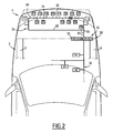
figure 2 est une vue similaire à celle de lafigure 1 , pour un second mode de réalisation de l'invention.
- the
figure 1 is a schematic representation, in plan view, of the front portion of a motor vehicle, the front block not forming part of the invention; and - the
figure 2 is a view similar to that of thefigure 1 , for a second embodiment of the invention.
Le véhicule automobile 1 représenté sur la
La structure porteuse 2 comprend notamment des longerons 6 s'étendant longitudinalement, l'un à droite et l'autre à gauche du véhicule.The
Le bloc avant 4 est rigidement fixé à des extrémités avant des longerons 6. Le bloc avant 4 est symbolisé ici par un trapèze dessiné en trait mixte. Le bloc avant 4 comprend typiquement un cadre rigide (non représenté), et une pluralité d'équipements rigidement fixés sur le cadre. Parmi ces équipements, peuvent figurer notamment le radiateur, le condenseur, des absorbeurs de chocs, une serrure de verrouillage du capot du véhicule, des lave-projecteur, des tuyauteries du véhicule, et un ou plusieurs des composants électriques suivants : un groupe moto-ventilateur 10 apte à créer une convexion forcée d'air au contact du radiateur, les projecteurs avant 12, un ou plusieurs capteurs de place disponible 14, un ou plusieurs capteurs d'aide au stationnement 16, un capteur de température ambiante 18, un radar 20 apte à détecter les obstacles à l'avant du véhicule, des feux antibrouillard 22, un klaxon 24, des volets motorisés 26 déplaçables en vue de gérer la ventilation de l'habitacle du véhicule, une ou plusieurs pompes 28 prévues pour projeter un liquide de nettoyage de la glace extérieure des projecteurs, un capteur de vitesse 30 faisant partie du dispositif de régulation de la vitesse du véhicule (cruise control), des capteurs de coussin gonflable 32, etc .... Le bloc avant comprend également un faisceau 34 d'alimentation électrique et de commande des composants électriques énumérés ci-dessus.The
L'ensemble des équipements ci-dessus est généralement monté sur le cadre du bloc avant dans l'atelier du fournisseur du bloc, puis le bloc avant avec les équipements prémontés est rapporté à l'avant du véhicule sur la structure de celui-ci. De même, le faisceau 34 est monté sur le cadre et raccordé aux différents composants électriques dans l'atelier du fournisseur, puis, une fois le bloc avant rapporté sur la structure du véhicule, le faisceau 34 est raccordé au réseau 36 d'alimentation électrique et de commande du véhicule.All the above equipment is generally mounted on the frame of the front block in the workshop of the supplier of the block, then the front block with pre-assembled equipment is attached to the front of the vehicle on the structure thereof. Similarly, the
A cette fin, le bloc avant 4 comporte des moyens 38 de connexion aptes à relier électriquement le faisceau 34 au réseau 36 en un point de connexion unique.To this end, the
Les moyens 38 sont constitués d'un connecteur électrique comportant un élément mâle 40 relié électriquement au réseau du véhicule, et un élément femelle 42, conjugué de l'élément mâle 40, relié électriquement au faisceau 34.The
Dans la
L'élément femelle 42 comprend plusieurs contacts femelles, chaque contact femelle étant électriquement en contact avec un des contacts mâles quand l'élément mâle est engagé dans l'élément femelle. Chaque contact femelle est par ailleurs connecté électriquement à un conducteur électrique du faisceau 34. Le faisceau 34 comprend une pluralité de conducteurs électriques de puissance, amenant la puissance électrique depuis le connecteur 38 jusqu'aux différents composants électriques. Le faisceau 34 comprend également des conducteurs de commande, transmettant des informations de commande aux composants électriques. Certains composants, comme par exemple le klaxon 24, sont reliés seulement à des conducteurs de puissance. D'autres composants, par exemple le radar 20, sont reliés à la fois à des conducteurs de puissance et à des conducteurs de commande.The
Ainsi, chaque conducteur de commande du faisceau 34 est électriquement relié par l'intermédiaire d'un contact mâle et d'un contact femelle à un conducteur de commande du réseau 36. De même, chaque conducteur de puissance du faisceau 34 est relié par l'intermédiaire d'un contact mâle et d'un contact femelle à un conducteur de puissance du réseau 36.Thus, each control conductor of the
Le raccordement électrique du faisceau 34 au réseau 36 est extrêmement simple. Une fois le bloc avant 4 rapporté sur la structure porteuse du véhicule, il suffit d'engager l'élément mâle 40 du connecteur électrique dans l'élément femelle 42. Une fois la connexion réalisée, chacun des composants électriques 10 à 32 est relié électriquement au réseau du véhicule.The electrical connection of the
Selon un mode de réalisation, représenté sur la
Les moyens de supervision 52 comprennent :
- des
moyens 56 pour identifier, parmi tous les composants électriques 10 à 32 du bloc avant, ceux qui sont opérationnels et ceux qui sont défaillants ; - des
moyens 58 pour identifier, pour chaque composant électrique défaillant, un type de défaillance ; - des
moyens 60 pour informer, pour certains composants électriques défaillants, l'unité de contrôle électronique qui gère ledit composant défaillant du type de défaillance identifié ; - des
moyens 62 pour sélectivement couper l'alimentation électrique de chaque composant électrique défaillant, en fonction au moins du type de défaillance identifié pour ledit composant électrique, et d'un paramètre représentatif de l'état du véhicule.
- means 56 for identifying, among all the
electrical components 10 to 32 of the front block, which ones are operational and which ones are faulty; - means 58 for identifying, for each failed electrical component, a type of failure;
- means 60 for informing, for certain failing electrical components, the electronic control unit that manages said failing component of the identified failure type;
- means 62 for selectively disconnecting the power supply of each failed electrical component, based at least on the type of failure identified for said electrical component, and a parameter representative of the state of the vehicle.
Les moyens 56 identifient les composants défaillants notamment en analysant l'évolution dans le temps de l'intensité et de la tension du courant fourni à chaque composant.The means 56 identify the faulty components including by analyzing the evolution over time of the intensity and voltage of the current supplied to each component.
Pour chaque composant électrique, les moyens 58 identifient la défaillance dans une liste prédéterminée. Cette liste peut être commune à tous les composants, ou être spécifique à chaque composant. Elle peut être partiellement commune à tous les composants. Par exemple, la liste peut comprendre les items suivants : composants totalement défaillants, composants partiellement défaillants, court-circuit, surcharge, surtension, etc ....For each electrical component, the
Comme indiqué plus haut, certains composants électriques du bloc avant sont associés à des unités de contrôle électronique faisant partie du réseau électrique du véhicule 36. On trouve par exemple parmi ces composants le groupe motoventilateur 10, les capteurs de place 14, les capteurs d'aide au stationnement 16, le radar 20, les volets 26, le capteur de vitesse 30, et les capteurs de coussin gonflable 32. Chacun de ces composants communique avec l'unité de contrôle correspondante par l'intermédiaire du réseau 36 et du faisceau 34. L'unité de contrôle électronique gère les composants électriques qui lui sont associés. En fonction des commandes des passagers du véhicule, et des informations disponibles concernant le fonctionnement du véhicule, l'unité de contrôle électronique commande la mise en service, l'arrêt, ou la modification du fonctionnement du composant, selon les circonstances.As indicated above, certain electrical components of the front block are associated with electronic control units forming part of the electrical network of the
Les moyens 60, quand ils détectent qu'un tel composant est défaillant, communiquent à l'unité de contrôle correspondante, l'identité du composant et la nature de la défaillance. En retour, l'unité de contrôle peut renvoyer un ordre concernant cet équipement, ou concernant tout autre composant du bloc avant piloté par ladite unité de contrôle.The means 60, when they detect that such a component is faulty, communicate to the corresponding control unit, the identity of the component and the nature of the failure. In return, the control unit may return an order concerning this equipment, or any other component of the front block controlled by said control unit.
Parallèlement à cela, les moyens 62 sont susceptibles de couper l'alimentation électrique de chaque composant électrique défaillant. A cette fin, les moyens 62 reçoivent d'une des unités de contrôle électrique du véhicule un paramètre représentatif de l'état du véhicule, spécialement élaboré dans ce but. Typiquement, ce paramètre indique si le véhicule est en état de rouler ou non. En effet, en cas de choc à l'avant du véhicule, les fonctions à préserver ne sont pas les mêmes selon que le véhicule est apte à rouler ou est immobilisé. Ainsi, si le véhicule est apte à rouler, il est important que les fonctions assurant une bonne visibilité au conducteur (projecteurs) ou contribuant à la sécurité du véhicule (capteurs de coussin gonflable, capteurs de vitesse pour le contrôle automatique de la vitesse du véhicule, ...) soient préservées. Au contraire, d'autres fonctions peuvent être coupées, telles que l'alimentation électrique des pompes pour le nettoyage des glaces des projecteurs, le pilotage des volets d'aération de l'habitacle, ....Alongside this, the
Au cas où le véhicule est immobilisé, un nombre plus faible de fonctions doit rester opérationnel, essentiellement les fonctions de signalisation (projecteurs, klaxons, ...).In case the vehicle is immobilized, a smaller number of functions must remain operational, essentially the signaling functions (projectors, horns, ...).
Ainsi, en fonction du paramètre représentatif de l'état du véhicule, de la liste des composants défaillants, et du type de défaillance identifié pour chaque composant défaillant, les moyens 62 vont couper ou non l'alimentation électrique de chaque composant. Pour cela, les moyens 62 utilisent des arbres de décision prédéterminés.Thus, depending on the representative parameter of the state of the vehicle, the list of failed components, and the type of failure identified for each failed component, the
Dans le mode de réalisation de la
En variante, les informations numériques échangées entre le boîtier 50 et les différentes unités de contrôle électroniques sont échangées sous forme multiplexées. Dans ce cas, le réseau 36 ne comporte typiquement qu'une seule entrée numérique au niveau du boîtier 50. Le boîtier 50 comporte alors des moyens 55 aptes à démultiplexer le signal numérique multiplexé reçu du réseau 36, et à multiplexer le signal numérique diffusé sur le réseau du véhicule par le boîtier 50.In a variant, the digital information exchanged between the
Dans tous les cas, les informations de commande sont transmises à partir du boîtier 50 vers les différents composants électriques du bloc avant sous forme analogique via le faisceau 34.In any case, the control information is transmitted from the
Le faisceau 34 peut présenter différentes architectures.The
Dans une première architecture non préférée, qui n'est pas représentée sur les
Le faisceau 34 peut également présenter une architecture dite en T, représentée sur la
Selon l'invention représentée sur la
Le bloc avant ou arrière décrit ci-dessus présente de multiples avantages.The front or rear block described above has many advantages.
Du fait qu'il comporte un unique moyen de connexion apte à relier électriquement le faisceau du bloc au réseau du véhicule, tous les composants électriques du bloc étant électriquement reliés aux moyens de connexion par l'intermédiaire du faisceau, le montage du bloc sur le véhicule est considérablement simplifié. Après avoir rapporté le bloc sur la structure porteuse du véhicule, il suffit de connecter le faisceau au réseau du véhicule par le moyen de connexion unique.Because it comprises a single connection means capable of electrically connecting the beam of the block to the vehicle network, all the electrical components of the block being electrically connected to the connection means via the beam, the mounting of the block on the vehicle is greatly simplified. After bringing the block on the carrier structure of the vehicle, it is sufficient to connect the beam to the vehicle network by the single connection means.
Le moyen de connexion peut avantageusement être un connecteur électrique, auquel cas il suffit d'engager l'élément mâle du connecteur dans l'élément femelle conjugué pour réaliser la connexion. La connexion est donc particulièrement simple et rapide.The connection means may advantageously be an electrical connector, in which case it is sufficient to engage the male element of the connector in the conjugate female element to make the connection. The connection is therefore particularly simple and fast.
Les moyens de connexion peuvent également comprendre un boîtier électronique assurant la supervision électrique des composants du bloc. Ceci permet de simplifier considérablement l'architecture électrique du véhicule. Ce boîtier peut comprendre notamment des moyens pour identifier les composants défaillants, des moyens pour identifier le type de défaillance desdits composants défaillants, et des moyens pour informer l'unité de contrôle électronique correspondante de la défaillance du composant et de la nature de la défaillance. Ces fonctions, dans l'état de la technique, étaient réparties entre les différentes unités de contrôle électronique du véhicule. Le fait de les rassembler au niveau du boîtier 50 permet de simplifier l'architecture électrique du véhicule.The connection means may also include an electronic box providing electrical supervision of the block components. This considerably simplifies the electrical architecture of the vehicle. This housing may comprise in particular means for identifying faulty components, means for identifying the type of failure of said failing components, and means for informing the corresponding electronic control unit of the failure of the component and the nature of the failure. These functions, in the state of the art, were distributed among the various electronic control units of the vehicle. Gathering them at the level of the
Par ailleurs, le boîtier 50 peut également comprendre des moyens pour couper l'alimentation électrique des composants défaillants, en fonction de la nature de la défaillance et en fonction de l'état du véhicule. Ainsi, selon que le véhicule est en état de rouler ou non, certaines fonctions sont préservées ou non. Ceci permet de mettre à l'arrêt des composants électriques dont le fonctionnement pourrait créer des situations dangereuses, et qui ne sont pas indispensables compte tenu de l'état du véhicule. La sûreté de fonctionnement du véhicule en est améliorée.Furthermore, the
De manière avantageuse, le boîtier 50 peut servir à loger des moyens de conversion analogiques/numériques de manière à convertir des signaux de commande numériques reçus des différentes unités de contrôle électronique du véhicule en signaux de commande analogiques reliés vers les composants électriques du bloc. Ceci permet de simplifier encore l'architecture électrique du véhicule.Advantageously, the
De manière à limiter le nombre de conducteurs du réseau électrique du véhicule, le boîtier 50 peut comporter des moyens de multiplexage/démultiplexage aptes à démultiplexer les signaux reçus du réseau du véhicule, ou à multiplexer les signaux diffusés vers le réseau du véhicule.In order to limit the number of conductors of the vehicle electrical network, the
Le faisceau peut avantageusement présenter une architecture en T, ce qui permet, en cas de coupure du faisceau dans l'une des branches du T, de préserver intégralement le fonctionnement des composants raccordés électriquement à l'autre branche du T.The beam may advantageously have a T-shaped architecture, which makes it possible, in the event of the beam to be cut in one of the branches of the T, to fully preserve the operation of the components electrically connected to the other branch of the T.
L'architecture en boucle, quant à elle, permet de préserver le fonctionnement de tous les composants électriques, même quand le faisceau est coupé en un point.The loop architecture, meanwhile, allows to preserve the operation of all electrical components, even when the beam is cut at a point.
Le bloc décrit ci-dessus peut présenter de multiples variantes.The block described above may have multiple variants.
L'invention a été décrite relativement à un bloc avant susceptible d'être rapporté à l'avant du véhicule. Elle est toutefois applicable également à un bloc arrière, susceptible d'être rapporté d'une pièce à l'arrière du véhicule. Le bloc arrière correspond typiquement au pare-chocs arrière du véhicule. II porte des composants électriques tels que l'éclairage de la plaque d'immatriculation arrière ou un radar d'aide au stationnement. II peut également comporter des organes de gestion de l'échappement du véhicule automobile. Le bloc arrière est typiquement rapporté sur les extrémités arrière des longerons du véhicule.The invention has been described with respect to a front block that can be attached to the front of the vehicle. However, it is also applicable to a rear block, likely to be returned from a room at the rear of the vehicle. The rear block typically corresponds to the rear bumper of the vehicle. It carries electrical components such as rear registration plate lighting or a parking aid radar. It may also include motor vehicle exhaust management bodies. The rear block is typically attached to the rear ends of the vehicle side members.
Dans le mode de réalisation où le faisceau présente une architecture en T, le faisceau peut comprendre plus de deux branches, par exemple trois, quatre, ou même plus de quatre branches. Toutes les branches peuvent être raccordées au même noeud. En variante, les branches peuvent être raccordées à différents noeuds répartis le long du tronc commun du faisceau. En variante également, chaque branche peut se subdiviser en plusieurs sous-branches, s'étendant à partir d'un ou plusieurs noeuds répartis le long de ladite branche.In the embodiment where the beam has a T-architecture, the beam may comprise more than two branches, for example three, four, or even more than four branches. All branches can be connected to the same node. Alternatively, the branches can be connected to different nodes distributed along the common core of the beam. Alternatively also, each branch can be subdivided into several sub-branches, extending from one or more nodes distributed along said branch.
Dans le cas où le faisceau présente une architecture en boucle, le faisceau peut comporter plusieurs boucles s'étendant à partir d'un même noeud, ou s'étendant à partir de plusieurs noeuds répartis le long du tronc commun. Certaines boucles peuvent également être reliées à des noeuds disposés dans une autre boucle. Le faisceau peut en outre comporter une ou plusieurs branches s'étendant à partir de noeuds situés soit dans le tronc commun soit dans une ou plusieurs boucles.In the case where the beam has a loop architecture, the beam may comprise a plurality of loops extending from the same node, or extending from several nodes distributed along the common trunk. Some loops may also be connected to nodes arranged in another loop. The beam may further comprise one or more branches extending from nodes located either in the common core or in one or more loops.
Dans le cas où les moyens de connexion du faisceau au réseau du véhicule sont un connecteur, l'élément mâle peut être relié au faisceau et l'élément femelle au réseau du véhicule.In the case where the connection means of the beam to the vehicle network are a connector, the male element can be connected to the beam and the female element to the vehicle network.
La gestion de la diversité des équipements des blocs avant et arrière selon les versions d'un même modèle de véhicules est facilitée. En effet, les versions d'entrée de gamme et de haut de gamme ne reçoivent pas les mêmes équipements. Le bloc avant décrit ci-dessus, dans le mode de réalisation comportant un boîtier électronique 50 de connexion du faisceau sur le réseau du véhicule, permet d'utiliser le même réseau d'alimentation électrique et de commande pour toutes les versions du véhicule. En revanche, le boîtier 50, le faisceau et les composants électriques du bloc avant varient d'une version à une autre. Les logiciels chargés dans les différentes unités de commande électroniques du véhicule peuvent être différents selon les versions.Managing the diversity of equipment of the front and rear blocks according to the versions of the same vehicle model is facilitated. Indeed, the entry-level and high-end versions do not receive the same equipment. The front block described above, in the embodiment comprising an
Il est par ailleurs possible de faire évoluer facilement les équipements du bloc avant ou arrière au cours de la vie du véhicule, sans modifier l'architecture du réseau d'alimentation électrique et de commande du véhicule. On entend ici par évolution le fait d'ajouter un composant, de le retirer, de le remplacer par un modèle différent, de le remplacer par type de composant différent, etc. A cette fin, le boîtier électronique 50 peut présenter, côté faisceau du bloc, une ou plusieurs entrées en attente. Comme précédemment, il peut être nécessaire de modifier les logiciels chargés dans les unités de contrôle électroniques du véhicule, sans modifier le réseau lui-même.It is also possible to easily upgrade the equipment of the front or rear block during the life of the vehicle, without changing the architecture of the power supply network and control of the vehicle. The term evolution is here understood to mean adding a component, removing it, replacing it with a different model, replacing it with a different type of component, etc. For this purpose, the
Claims (12)
- Front (4) or rear end for a motor vehicle, the vehicle comprising a rigid structure (2) and a network (36) for electrical supply and/or control, the end (4) being arranged to be attached to said rigid structure (2) at the front or rear of the vehicle, the end (4) comprising a set of electrical components (10 to 32), a wiring harness (34) for electrical supply and/or control of the electrical components (10 to 32) and at least one connection means (38) arranged to electrically connect the wiring harness (34) of the end (4) to the vehicle network (36), the end (4) having a single connection means (38) arranged to electrically connect the wiring harness (34) of the end (4) to the vehicle network (36), all the electrical components (10 to 32) of the end (4) being electrically connected to the connection means (38) by way of the wiring harness (34),
characterised in that the wiring harness (34) of the end (4) comprises at least one node (70, 78) electrically connected to the means (38) for connection to the vehicle network (36) and two separate branches (84, 82) extending starting from the node (70, 78), a sub-set of the electrical components (10 to 32) being electrically connected to one of the branches (74, 82) and another sub-set of the electrical components (10 to 32) being electrically connected to the other of the branches (74, 82),
and in that the two branches (82) of the electrical wiring harness are electrically connected to one another at a second point (84) separate from the node (78) and form a loop, at least some of the electrical components (10 to 32) being electrically connected to the node (78) by the two branches (82). - Front or rear end according to claim 1, characterised in that the connection means (38) is an electrical connector having a male element (40) electrically connected to one of the wiring harness (34) of the end (4) and the vehicle network (36), and a female element (42) mating with the male element (40) and electrically connected to the other of the wiring harness (34) of the end (4) and the vehicle network (36).
- Front or rear end according to claim 1, characterised in that the connection means (38) comprises means (52) for electrical monitoring of the end (4) capable, in the event of a defect of some of the electrical components (10 to 32) of the end (4), of identifying, from among the electrical components (10 to 32) of the end (4), the electrical components (10 to 32) which are detective and the electrical components (10 to 32) which are still operational.
- Front or rear end according to claim 3, characterised in that the electrical monitoring means (52) comprise means (58) for identifying, for each defective electrical component (10 to 32), the type of defect.
- Front or rear end according to claim 4, characterised in that the vehicle network (36) comprises a plurality of electronic checking units (46, 48) each arranged to have control over one or more of the electrical components (10 to 32) of the end (4), the monitoring means (52) comprising means (60) for informing, for each defective electrical component (10 to 32), the corresponding electronic checking unit (46, 48) of the type of defect identified for said electrical component (10 to 32).
- Front or rear end according to claim 5 or 6, characterised in that the monitoring means (52) comprise means (62) for selective interruption of the electrical supply of each defective electrical component (10 to 32) as a function of, at least, the type of defect identified for said electrical component (10 to 32).
- Front or rear end according to claim 6, characterised in that the means (62) for interruption of the electrical supply are arranged for selective interruption of the electrical supply of each defective electrical component (10 to 32) also as a function of a parameter which is representative of the state of the vehicle, said parameter indicating if the vehicle is in a state to be driven or not.
- Front or rear end according to any one of claims 3 to 7, characterised in that the connection means (38) comprise analogue/digital conversion means (54) arranged to convert a digital signal received from the vehicle network (36) into an analogue signal transmitted to the wiring harness (34) of the end (4) and arranged to convert an analogue signal received from the wiring harness (34) of the end (4) into a digital signal transmitted to the vehicle network (36).
- Front or rear end according to claim 8, characterised in that the connection means (38) comprise multiplexing/demultiplexing means (55) arranged to demultiplex a multiplexed digital signal received from the vehicle network (36) and to multiplex the digital signal transmitted to the vehicle network (36).
- Front or rear end according to any one of the preceding claims, characterised in that the end (4) is a front end.
- Front or rear end according to claim 10, characterised in that the end (4) comprises a rigid frame and at least one radiator rigidly fixed to the frame.
- Front or rear end according to any ane of the preceding claims, characterised in that the wiring harness (34) is a wiring harness for electrical supply and control of the electrical components of the end (4).
Applications Claiming Priority (1)
| Application Number | Priority Date | Filing Date | Title |
|---|---|---|---|
| FR0756869A FR2919549B1 (en) | 2007-08-01 | 2007-08-01 | FRONT OR REAR BLOCK OF MOTOR VEHICLE |
Publications (3)
| Publication Number | Publication Date |
|---|---|
| EP2022679A2 EP2022679A2 (en) | 2009-02-11 |
| EP2022679A3 EP2022679A3 (en) | 2009-03-04 |
| EP2022679B1 true EP2022679B1 (en) | 2011-09-14 |
Family
ID=39203293
Family Applications (1)
| Application Number | Title | Priority Date | Filing Date |
|---|---|---|---|
| EP20080161182 Expired - Fee Related EP2022679B1 (en) | 2007-08-01 | 2008-07-25 | Front or rear block of an automobile |
Country Status (2)
| Country | Link |
|---|---|
| EP (1) | EP2022679B1 (en) |
| FR (1) | FR2919549B1 (en) |
Family Cites Families (5)
| Publication number | Priority date | Publication date | Assignee | Title |
|---|---|---|---|---|
| JPS5298946A (en) * | 1976-02-13 | 1977-08-19 | Toyo Kogyo Co | Wiring system for automobile |
| JP3011521B2 (en) | 1991-03-28 | 2000-02-21 | 矢崎総業株式会社 | Electric wiring structure for vehicles |
| FR2794085B1 (en) * | 1999-05-28 | 2001-08-17 | Valeo Climatisation | VEHICLE DASHBOARD WITH ELECTRICAL HARNESS |
| JP2002368766A (en) * | 2001-06-05 | 2002-12-20 | Auto Network Gijutsu Kenkyusho:Kk | Wire harness system |
| DE10141263B4 (en) * | 2001-08-23 | 2005-07-07 | Bayerische Motoren Werke Ag | Modular vehicle |
-
2007
- 2007-08-01 FR FR0756869A patent/FR2919549B1/en not_active Expired - Fee Related
-
2008
- 2008-07-25 EP EP20080161182 patent/EP2022679B1/en not_active Expired - Fee Related
Also Published As
| Publication number | Publication date |
|---|---|
| FR2919549B1 (en) | 2010-02-19 |
| EP2022679A2 (en) | 2009-02-11 |
| FR2919549A1 (en) | 2009-02-06 |
| EP2022679A3 (en) | 2009-03-04 |
Similar Documents
| Publication | Publication Date | Title |
|---|---|---|
| FR3043873A1 (en) | ELECTRIC VEHICLE EQUIPPED WITH A COMMUNICATION NETWORK. | |
| EP0567403A1 (en) | Help panel for control and/or power supply of electrical elements in a vehicle | |
| FR2787753A3 (en) | Safety warning lamp auxiliary system for road vehicle | |
| FR2578067A1 (en) | CONTROLLED POWER DISTRIBUTION SYSTEM IN A MOTOR VEHICLE | |
| EP1280674A1 (en) | Equipment module for a motor vehicle opening panel | |
| EP2022679B1 (en) | Front or rear block of an automobile | |
| EP2022695B1 (en) | Electrical subassembly of an automobile, associated vehicle and method. | |
| FR2887394A1 (en) | METHOD AND DEVICE FOR BALLAST MANAGEMENT, IN PARTICULAR FOR A MOTOR VEHICLE PROJECTOR | |
| FR2762276A1 (en) | METHOD AND DEVICE FOR CONTROLLING A BRAKING SYSTEM OF A MOTOR VEHICLE | |
| EP4204252A1 (en) | Vehicle secured against the risk of loss of a service battery | |
| EP2699452A1 (en) | Method and system for controlling the lighting of the brake lights of a motor vehicle, and vehicle provided with such a system | |
| WO2011114032A1 (en) | Device for detecting the disconnection of a battery from a power supply network | |
| FR3096756A1 (en) | Method for controlling a signaling system of a motor vehicle | |
| FR2978094A1 (en) | Device for checking traffic lights of e.g. terrestrial car, has acceleration unit for providing initial lighting power by receiving information indicating that average acceleration of vehicle achieves required level | |
| FR2949865A1 (en) | Method for assisting diagnosis of failure of mechatronic controller in motor vehicle, involves storing product context that comprises failure function utilization data and input/output state of mechatronic controller | |
| EP1170179B1 (en) | Control system of vehicle driving devices | |
| FR3007345A1 (en) | DEVICE FOR LOCKING ELECTRICAL COMPONENTS OF A VEHICLE VIA DIGITAL COMMUNICATION | |
| FR2958600A1 (en) | Electrical equipments e.g. windscreen wipers, controlling device for on-board computer of motor vehicle e.g. electric car, has control units receiving information signaling of displacement of motor vehicle at speed lower/equal to threshold | |
| FR3060935A1 (en) | COMPUTER SUPPORT COMPRISING MOUNTING MEANS FOR AN ADDITIONAL FUSE HOUSING | |
| FR3081405A1 (en) | MODULAR COMMUNICATION DEVICE FOR VEHICLE. | |
| FR2852709A1 (en) | SYSTEM FOR SECURING THE OUTPUTS OF CONTROL SIGNALS OF AN INFORMATION PROCESSING UNIT | |
| FR3128163A1 (en) | Electric motor vehicle resulting from the conversion of an original heat engine version of the vehicle | |
| FR3052710A1 (en) | INTERFACE HOUSING BETWEEN A MOTOR VEHICLE AND A TRACT VEHICLE | |
| FR3020022A1 (en) | DEVICE FOR CONTROLLING LIGHTING AND / OR SIGNALING LAMPS WITH AN ELECTRONIC CONTROL SYSTEM IN A MANUAL LIGHTING CONTROL ARRESTOR | |
| FR2482024A1 (en) | Fault detection and correction circuit for vehicle lamps - uses transistor diode and relay logic to monitor bulb failure and to provide lost function in another bulb |
Legal Events
| Date | Code | Title | Description |
|---|---|---|---|
| PUAI | Public reference made under article 153(3) epc to a published international application that has entered the european phase |
Free format text: ORIGINAL CODE: 0009012 |
|
| PUAL | Search report despatched |
Free format text: ORIGINAL CODE: 0009013 |
|
| AK | Designated contracting states |
Kind code of ref document: A2 Designated state(s): AT BE BG CH CY CZ DE DK EE ES FI FR GB GR HR HU IE IS IT LI LT LU LV MC MT NL NO PL PT RO SE SI SK TR |
|
| AX | Request for extension of the european patent |
Extension state: AL BA MK RS |
|
| AK | Designated contracting states |
Kind code of ref document: A3 Designated state(s): AT BE BG CH CY CZ DE DK EE ES FI FR GB GR HR HU IE IS IT LI LT LU LV MC MT NL NO PL PT RO SE SI SK TR |
|
| AX | Request for extension of the european patent |
Extension state: AL BA MK RS |
|
| 17P | Request for examination filed |
Effective date: 20090610 |
|
| 17Q | First examination report despatched |
Effective date: 20090721 |
|
| RIC1 | Information provided on ipc code assigned before grant |
Ipc: B60R 16/02 20060101AFI20101206BHEP Ipc: B60R 16/03 20060101ALI20101206BHEP |
|
| GRAP | Despatch of communication of intention to grant a patent |
Free format text: ORIGINAL CODE: EPIDOSNIGR1 |
|
| AKX | Designation fees paid |
Designated state(s): DE FR GB |
|
| GRAS | Grant fee paid |
Free format text: ORIGINAL CODE: EPIDOSNIGR3 |
|
| GRAA | (expected) grant |
Free format text: ORIGINAL CODE: 0009210 |
|
| AK | Designated contracting states |
Kind code of ref document: B1 Designated state(s): DE FR GB |
|
| REG | Reference to a national code |
Ref country code: GB Ref legal event code: FG4D Free format text: NOT ENGLISH |
|
| REG | Reference to a national code |
Ref country code: DE Ref legal event code: R096 Ref document number: 602008009735 Country of ref document: DE Effective date: 20111110 |
|
| PLBE | No opposition filed within time limit |
Free format text: ORIGINAL CODE: 0009261 |
|
| STAA | Information on the status of an ep patent application or granted ep patent |
Free format text: STATUS: NO OPPOSITION FILED WITHIN TIME LIMIT |
|
| 26N | No opposition filed |
Effective date: 20120615 |
|
| REG | Reference to a national code |
Ref country code: DE Ref legal event code: R097 Ref document number: 602008009735 Country of ref document: DE Effective date: 20120615 |
|
| REG | Reference to a national code |
Ref country code: FR Ref legal event code: PLFP Year of fee payment: 9 |
|
| REG | Reference to a national code |
Ref country code: FR Ref legal event code: PLFP Year of fee payment: 10 |
|
| PGFP | Annual fee paid to national office [announced via postgrant information from national office to epo] |
Ref country code: GB Payment date: 20170620 Year of fee payment: 10 Ref country code: FR Payment date: 20170621 Year of fee payment: 10 |
|
| PGFP | Annual fee paid to national office [announced via postgrant information from national office to epo] |
Ref country code: DE Payment date: 20170620 Year of fee payment: 10 |
|
| REG | Reference to a national code |
Ref country code: DE Ref legal event code: R119 Ref document number: 602008009735 Country of ref document: DE |
|
| GBPC | Gb: european patent ceased through non-payment of renewal fee |
Effective date: 20180725 |
|
| PG25 | Lapsed in a contracting state [announced via postgrant information from national office to epo] |
Ref country code: FR Free format text: LAPSE BECAUSE OF NON-PAYMENT OF DUE FEES Effective date: 20180731 Ref country code: GB Free format text: LAPSE BECAUSE OF NON-PAYMENT OF DUE FEES Effective date: 20180725 Ref country code: DE Free format text: LAPSE BECAUSE OF NON-PAYMENT OF DUE FEES Effective date: 20190201 |