EP2022602A1 - Device for removing chips in machine tools - Google Patents
Device for removing chips in machine tools Download PDFInfo
- Publication number
- EP2022602A1 EP2022602A1 EP08159503A EP08159503A EP2022602A1 EP 2022602 A1 EP2022602 A1 EP 2022602A1 EP 08159503 A EP08159503 A EP 08159503A EP 08159503 A EP08159503 A EP 08159503A EP 2022602 A1 EP2022602 A1 EP 2022602A1
- Authority
- EP
- European Patent Office
- Prior art keywords
- cutting
- cutting means
- chips
- suction
- hood
- Prior art date
- Legal status (The legal status is an assumption and is not a legal conclusion. Google has not performed a legal analysis and makes no representation as to the accuracy of the status listed.)
- Granted
Links
- 238000003754 machining Methods 0.000 claims abstract description 21
- 239000000463 material Substances 0.000 claims abstract description 13
- 239000004033 plastic Substances 0.000 claims abstract description 10
- 229920003023 plastic Polymers 0.000 claims abstract description 10
- 239000002023 wood Substances 0.000 description 4
- 238000009966 trimming Methods 0.000 description 3
- 238000004026 adhesive bonding Methods 0.000 description 1
- 238000012423 maintenance Methods 0.000 description 1
- 230000007257 malfunction Effects 0.000 description 1
- 238000011144 upstream manufacturing Methods 0.000 description 1
Images


Classifications
-
- B—PERFORMING OPERATIONS; TRANSPORTING
- B23—MACHINE TOOLS; METAL-WORKING NOT OTHERWISE PROVIDED FOR
- B23Q—DETAILS, COMPONENTS, OR ACCESSORIES FOR MACHINE TOOLS, e.g. ARRANGEMENTS FOR COPYING OR CONTROLLING; MACHINE TOOLS IN GENERAL CHARACTERISED BY THE CONSTRUCTION OF PARTICULAR DETAILS OR COMPONENTS; COMBINATIONS OR ASSOCIATIONS OF METAL-WORKING MACHINES, NOT DIRECTED TO A PARTICULAR RESULT
- B23Q11/00—Accessories fitted to machine tools for keeping tools or parts of the machine in good working condition or for cooling work; Safety devices specially combined with or arranged in, or specially adapted for use in connection with, machine tools
- B23Q11/0042—Devices for removing chips
- B23Q11/0046—Devices for removing chips by sucking
-
- B—PERFORMING OPERATIONS; TRANSPORTING
- B02—CRUSHING, PULVERISING, OR DISINTEGRATING; PREPARATORY TREATMENT OF GRAIN FOR MILLING
- B02C—CRUSHING, PULVERISING, OR DISINTEGRATING IN GENERAL; MILLING GRAIN
- B02C18/00—Disintegrating by knives or other cutting or tearing members which chop material into fragments
- B02C18/06—Disintegrating by knives or other cutting or tearing members which chop material into fragments with rotating knives
-
- B—PERFORMING OPERATIONS; TRANSPORTING
- B02—CRUSHING, PULVERISING, OR DISINTEGRATING; PREPARATORY TREATMENT OF GRAIN FOR MILLING
- B02C—CRUSHING, PULVERISING, OR DISINTEGRATING IN GENERAL; MILLING GRAIN
- B02C18/00—Disintegrating by knives or other cutting or tearing members which chop material into fragments
- B02C18/06—Disintegrating by knives or other cutting or tearing members which chop material into fragments with rotating knives
- B02C18/14—Disintegrating by knives or other cutting or tearing members which chop material into fragments with rotating knives within horizontal containers
Definitions
- the invention relates to a device for removing machining chips made of plastics or similar materials from a machine tool.
- the invention relates to a device for removing machining chips made of plastics or similar materials from edgebanding machines used in the woodworking industry for edgebanding panels made of wood or similar materials.
- edgebanding machines are used for applying, and subsequently chip-forming machining, edges made of plastics or similar materials on a panel made of wood or similar materials.
- Such edgebanding machines comprise a frame supporting a movement line extending along an advance direction of the panel.
- the frame supports a plurality of work stations, comprising, for example, an edgebanding station and a finishing station.
- the edgebanding station comprises an edgebanding unit arranged for applying to each side of the panel, by gluing, an edge made of plastics.
- This edge has dimensions that are greater than a thickness of the panel, i.e. the edge exceeds the panel, so as to cover completely the panel.
- the finishing station positioned downstream of the edgebanding station with respect to the advance direction, comprises a plurality of substations, each of which is provided with a cutting unit.
- Each cutting unit comprises respective cutting tools, such as, for example, shaped bits, for performing on such edges chip-forming machinings.
- Such cutting units may, for example, comprise respectively a trimming unit, an edge-sanding unit and a rounding/profiling unit.
- the trimming unit removes an upper part and a lower part of the edge that exceeds the thickness of the panel
- the edge-sanding unit makes a connecting radius between the edge applied to the thickness of the panel and the upper and lower surface of the panel, whilst the rounding/profiling unit rounds the profile of the edge after it has been applied to the panel.
- the cutting units i.e. the trimming unit, the edge-sanding unit and the rounding/profiling unit, produce chips, i.e. machining chips.
- Such chips adhere, not only to the panels being machined, but also to the cutting tools and to parts of the edgebanding machine adjacent to the cutting tools, and may cause malfunctions of the edgebanding machine, such as, for example jams, which can cause frequent machine downtime in addition to a worsening of the aesthetic quality of the machining.
- Devices for removing machining chips from an edgebanding machine comprise a suction hood.
- This suction hood is fixed to the aforesaid cutting units and sucks and removes the machining chips.
- this suction hood comprises an inlet and an outlet for such chips, such inlet being positioned near the aforesaid cutting tools and such outlet being connected to a further device arranged for making a vacuum between the inlet and the outlet.
- a drawback of the devices disclosed above is that they are not very effective.
- the subsequent yarns tend to be attached to the first yarn until they rapidly form a hank that is such as to obstruct the suction hood.
- An object of the invention is to improve the devices for removing chips made of plastics or similar materials from a machine tool, in particular from an edgebanding machine.
- a further object is to provide more effective devices than known devices.
- a device for removing machining chips made of plastics or similar materials comprising suction-hood means provided with an inlet and with an outlet for said chips and arranged for sucking said chips between said inlet and said outlet, characterised in that there is provided cutting means, received in said suction-hood means between said inlet and said outlet, for chopping up said chips.
- said cutting means for example positioned near said inlet, intercepts said chips and chops up said chips, reducing the chips into small parts that are not liable to get caught in and are more easily suctionable from said suction-hood means.
- an edgebanding machine for edgebanding panels made of wood or similar materials comprising a device as disclosed in the aforesaid first aspect.
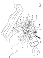
- FIG. 1 With reference to Figure 1 there is shown a first embodiment A1 of a device 1 for removing a machining chip 2 made of plastics or similar materials from a machine tool, which is not shown, in particular from an edgebanding machine used in the woodworking industry foe edgebanding a panel 3 made of wood or similar materials.
- the device 1 is fixed to a cutting unit, or operating unit, which is not shown, of the edgebanding machine.
- the cutting unit comprises a cutting tool 4 for machining by chip-forming machining an edge 5 previously applied to the panel 3.
- the device 1 comprises a tubular suction hood 6, to suck the chips 2.
- the suction hood 6 comprises a first portion 10 extending substantially parallely to a first axis X and a second portion 11, partially shown by a broken line, extending substantially parallely to a second axis Y, transverse to the first axis X.
- the first portion 10 is positioned upstream of the second portion 11, having substantially the shape of a hollow cylinder, with respect to a suction direction A of the chips 2.
- the second portion 11 has the shape of a hollow parallelepipedon with a rectangular or square base.
- the suction hood 6 comprises an inlet 7, obtained in the first portion 10, and an outlet 8, obtained in the second portion 11, for the chips 2.
- the inlet 7 is positioned near a working zone 9 of the cutting tool 4, whilst the outlet 8 is connected to a further device, which is not shown, arranged for making a vacuum inside the suction hood 6 for sucking the chips 2.
- the device 1 further comprises cutting means 12 for chopping up, inside the suction hood 6, the chips 2 into parts 30 of reduced dimensions.
- the cutting means 12 is positioned inside the suction hood 6 near the inlet 7.
- the cutting means 12 comprises a plurality of first blades 13.
- Each first blade 13 has a first curvilinear cutting profile 14, which is for example helical.
- the first blades 13 are supported by, and interposed between, a first plate 15 and a second plate 16.
- the first plate 15 and the second plate 16, which are opposite one another, are substantially disc-shaped and are substantially perpendicular to a rotation axis Z around which the first blades 13 are rotatable, this rotation axis Z being transverse to the first axis X and to the second axis Y.
- first blades 13 are fixed, suitably spaced, at respective ends of the first blades 13, to a first edge portion 17 and to a second edge portion 18, that are substantially circular, respectively of the first plate 15 and of the second plate 16, so that the first cutting profiles 14 project outside the first edge portion 17 and the second edge portion 18.
- the device 1 further comprises a first shaft 19 and a second shaft, which is not shown, both extending along and rotatable around the rotation axis Z.
- first shaft 19 and the second shaft are respectively fixed to and project outside from the first plate 15 and second plate 16.
- first shaft 19 and the second shaft are rotatably fixed to the second portion 11 by respectively a first bearing 21 and a second bearing 22.
- the first shaft 19 projects outside the suction hood 6 and is connected to and rotated by a rotor 23 provided with blading 24.
- the device 1 further comprises dispensing means 25 for dispensing pressurised air arranged for dispensing pressurised air 26 to the blading 24 for rotating the blading.
- the cutting means 12 further comprises a second blade 27 and a third blade, which is not shown, which are opposite one another, that are fixed to an inner wall 28 of the suction hood 6.
- the second blade 27 and the third blade extending substantially parallely to the rotation axis Z, are positioned downstream of the first blades 13 with respect to the suction direction A, and on opposite parts of the first plate 15 and the second plate 16.
- the second blade 27 and the third blade comprise respectively a second cutting profile 29 and a third cutting profile, which is not shown, which are mutually opposite, and arranged for interacting with the first cutting profiles 14 for chopping up the chips 2.
- the second cutting profile 29 and the third cutting profile are substantially rectilinear.
- the dispensing means 25 dispenses the pressurised air 26 that rotates the blading 24.
- the blading 24 is connected to and rotates the first shaft 19, which in turn rotates, via the first plate 15, the first blades 13.
- the long, thin and corrugated chips 2 produced by the cutting tool 4 and sucked inside the suction hood 6 is chopped up by the first rotating blades 13 cooperating with the second fixed blade 27 and with the third fixed blade.
- the rotor 23 is received inside the suction hood 6 and is rotated by the vacuum created by the aforesaid further device.
- the first shaft 19 is fixed to, and rotated by a motor 31, for example an electric motor.
- the cutting means 12 intercepts the chips 2 and chops up the chips 2 by reducing the chips 2 into small parts 30 that are not liable to get caught in and are more easily suctionable from the suction hood 6.
Landscapes
- Engineering & Computer Science (AREA)
- Food Science & Technology (AREA)
- Mechanical Engineering (AREA)
- Auxiliary Devices For Machine Tools (AREA)
- Valve Device For Special Equipments (AREA)
- Details Of Cutting Devices (AREA)
Abstract
Description
- The invention relates to a device for removing machining chips made of plastics or similar materials from a machine tool.
- In particular, the invention relates to a device for removing machining chips made of plastics or similar materials from edgebanding machines used in the woodworking industry for edgebanding panels made of wood or similar materials.
- In particular, such edgebanding machines are used for applying, and subsequently chip-forming machining, edges made of plastics or similar materials on a panel made of wood or similar materials.
- Such edgebanding machines comprise a frame supporting a movement line extending along an advance direction of the panel.
- The frame supports a plurality of work stations, comprising, for example, an edgebanding station and a finishing station. The edgebanding station comprises an edgebanding unit arranged for applying to each side of the panel, by gluing, an edge made of plastics.
- This edge has dimensions that are greater than a thickness of the panel, i.e. the edge exceeds the panel, so as to cover completely the panel.
- The finishing station, positioned downstream of the edgebanding station with respect to the advance direction, comprises a plurality of substations, each of which is provided with a cutting unit.
- Each cutting unit comprises respective cutting tools, such as, for example, shaped bits, for performing on such edges chip-forming machinings.
- Such cutting units may, for example, comprise respectively a trimming unit, an edge-sanding unit and a rounding/profiling unit.
- In particular, the trimming unit removes an upper part and a lower part of the edge that exceeds the thickness of the panel, the edge-sanding unit makes a connecting radius between the edge applied to the thickness of the panel and the upper and lower surface of the panel, whilst the rounding/profiling unit rounds the profile of the edge after it has been applied to the panel.
- In use, the cutting units, i.e. the trimming unit, the edge-sanding unit and the rounding/profiling unit, produce chips, i.e. machining chips.
- Such chips adhere, not only to the panels being machined, but also to the cutting tools and to parts of the edgebanding machine adjacent to the cutting tools, and may cause malfunctions of the edgebanding machine, such as, for example jams, which can cause frequent machine downtime in addition to a worsening of the aesthetic quality of the machining.
- For this reason, a device for removing machining chips is fixed to each cutting unit.
- Devices for removing machining chips from an edgebanding machine are known that comprise a suction hood.
- This suction hood is fixed to the aforesaid cutting units and sucks and removes the machining chips.
- In particular, this suction hood comprises an inlet and an outlet for such chips, such inlet being positioned near the aforesaid cutting tools and such outlet being connected to a further device arranged for making a vacuum between the inlet and the outlet.
- A drawback of the devices disclosed above is that they are not very effective.
- In fact, such devices cause frequent downtime of the edgebanding machine with consequent reduction of the productivity of the edgebanding machine.
- This is due to the fact that the aforesaid machining chips, having the shape of long, thin and corrugated yarns, easily tend to get caught inside the suction hood.
- In particular, in use, after a first yarn has got caught, the subsequent yarns tend to be attached to the first yarn until they rapidly form a hank that is such as to obstruct the suction hood.
- Consequently, frequent machine downtime is required for maintenance interventions to remove such a hank from the suction hood.
- Sometimes, in order to overcome this drawback, an aspirating power of the further device was increased to achieve the vacuum, or the diameter of the suction hood was increased.
- However, this not only does not solve the aforesaid drawback but also increases the costs to be borne to make the device and increases the overall dimensions of the device.
- An object of the invention is to improve the devices for removing chips made of plastics or similar materials from a machine tool, in particular from an edgebanding machine.
- A further object is to provide more effective devices than known devices.
- In a first aspect of the invention there is provided a device for removing machining chips made of plastics or similar materials, comprising suction-hood means provided with an inlet and with an outlet for said chips and arranged for sucking said chips between said inlet and said outlet, characterised in that there is provided cutting means, received in said suction-hood means between said inlet and said outlet, for chopping up said chips.
- Owing to this aspect of the invention it is possible to make a device for removing machining chips that is more effective than known devices.
- In fact, said cutting means, for example positioned near said inlet, intercepts said chips and chops up said chips, reducing the chips into small parts that are not liable to get caught in and are more easily suctionable from said suction-hood means.
- In a second aspect of the invention an edgebanding machine is provided for edgebanding panels made of wood or similar materials comprising a device as disclosed in the aforesaid first aspect.
- The invention can be better understood and implemented with reference to the attached drawings that illustrate some embodiments thereof by way of non-limiting example, in which:
-
Figure 1 is a schematic perspective view of a first embodiment of a device for removing machining chips; -
Figure 2 is a schematic perspective view of a second embodiment of a device for removing machining chips; -
Figure 3 is a schematic perspective view of a third embodiment of a device for removing machining chips. - With reference to
Figure 1 there is shown a first embodiment A1 of adevice 1 for removing amachining chip 2 made of plastics or similar materials from a machine tool, which is not shown, in particular from an edgebanding machine used in the woodworking industry foe edgebanding apanel 3 made of wood or similar materials. - The
device 1 is fixed to a cutting unit, or operating unit, which is not shown, of the edgebanding machine. - The cutting unit comprises a
cutting tool 4 for machining by chip-forming machining anedge 5 previously applied to thepanel 3. - The
device 1 comprises atubular suction hood 6, to suck thechips 2. - The
suction hood 6 comprises afirst portion 10 extending substantially parallely to a first axis X and asecond portion 11, partially shown by a broken line, extending substantially parallely to a second axis Y, transverse to the first axis X. - In particular, the
first portion 10 is positioned upstream of thesecond portion 11, having substantially the shape of a hollow cylinder, with respect to a suction direction A of thechips 2. - In an embodiment of the invention, which is not shown, the
second portion 11 has the shape of a hollow parallelepipedon with a rectangular or square base. - The
suction hood 6 comprises aninlet 7, obtained in thefirst portion 10, and anoutlet 8, obtained in thesecond portion 11, for thechips 2. - In particular, the
inlet 7 is positioned near a workingzone 9 of thecutting tool 4, whilst theoutlet 8 is connected to a further device, which is not shown, arranged for making a vacuum inside thesuction hood 6 for sucking thechips 2. - The
device 1 further comprises cutting means 12 for chopping up, inside thesuction hood 6, thechips 2 intoparts 30 of reduced dimensions. - The
cutting means 12 is positioned inside thesuction hood 6 near theinlet 7. - The cutting means 12 comprises a plurality of
first blades 13. - Each
first blade 13 has a firstcurvilinear cutting profile 14, which is for example helical. - The
first blades 13 are supported by, and interposed between, afirst plate 15 and asecond plate 16. - The
first plate 15 and thesecond plate 16, which are opposite one another, are substantially disc-shaped and are substantially perpendicular to a rotation axis Z around which thefirst blades 13 are rotatable, this rotation axis Z being transverse to the first axis X and to the second axis Y. - In particular, the
first blades 13 are fixed, suitably spaced, at respective ends of thefirst blades 13, to afirst edge portion 17 and to asecond edge portion 18, that are substantially circular, respectively of thefirst plate 15 and of thesecond plate 16, so that thefirst cutting profiles 14 project outside thefirst edge portion 17 and thesecond edge portion 18. - The
device 1 further comprises afirst shaft 19 and a second shaft, which is not shown, both extending along and rotatable around the rotation axis Z. - In particular, the
first shaft 19 and the second shaft are respectively fixed to and project outside from thefirst plate 15 andsecond plate 16. - Further, the
first shaft 19 and the second shaft are rotatably fixed to thesecond portion 11 by respectively a first bearing 21 and a second bearing 22. - In particular, the
first shaft 19 projects outside thesuction hood 6 and is connected to and rotated by arotor 23 provided withblading 24. - The
device 1 further comprises dispensing means 25 for dispensing pressurised air arranged for dispensingpressurised air 26 to theblading 24 for rotating the blading. - The cutting means 12 further comprises a
second blade 27 and a third blade, which is not shown, which are opposite one another, that are fixed to aninner wall 28 of thesuction hood 6. - In particular, the
second blade 27 and the third blade, extending substantially parallely to the rotation axis Z, are positioned downstream of thefirst blades 13 with respect to the suction direction A, and on opposite parts of thefirst plate 15 and thesecond plate 16. - The
second blade 27 and the third blade comprise respectively asecond cutting profile 29 and a third cutting profile, which is not shown, which are mutually opposite, and arranged for interacting with thefirst cutting profiles 14 for chopping up thechips 2. - In particular, the
second cutting profile 29 and the third cutting profile are substantially rectilinear. - In an embodiment of the invention, which is not shown, there is provided a single blade fixed to the
inner wall 28. - In use, the dispensing means 25 dispenses the
pressurised air 26 that rotates theblading 24. - The
blading 24 is connected to and rotates thefirst shaft 19, which in turn rotates, via thefirst plate 15, thefirst blades 13. - In this manner, the long, thin and
corrugated chips 2 produced by thecutting tool 4 and sucked inside thesuction hood 6 is chopped up by the first rotatingblades 13 cooperating with the second fixedblade 27 and with the third fixed blade. - With reference to
Figure 2 there is shown a second embodiment A2 of thedevice 1. - In the second embodiment A2, the
rotor 23 is received inside thesuction hood 6 and is rotated by the vacuum created by the aforesaid further device. - With reference to
Figure 3 there is shown a third embodiment A3 of thedevice 1. - In the third embodiment A3, the
first shaft 19 is fixed to, and rotated by amotor 31, for example an electric motor. - It should be noted how the
device 1 disclosed above is more effective than known devices. - In fact, the cutting means 12, intercepts the
chips 2 and chops up thechips 2 by reducing thechips 2 intosmall parts 30 that are not liable to get caught in and are more easily suctionable from thesuction hood 6.
Claims (17)
- Device for removing machining chips (2) made of plastics or similar materials, comprising suction-hood means (6) provided with an inlet (7) and with an outlet (8) for said chips (2) and arranged for sucking said chips (2) between said inlet (7) and said outlet (8), characterised in that there is provided cutting means (12), received in said suction-hood means (6) between said inlet (7) and said outlet (8), for chopping up said chips (2).
- Device according to claim 1, wherein said cutting means (12) is positioned near said inlet (7).
- Device according to claim 1, or 2, wherein said cutting means (12) comprises first cutting means (13) rotatably supported by said suction-hood means (6).
- Device according to claim 3, wherein said first cutting means (13) is rotatable around, and extends substantially parallely to a rotation axis (Z) that is transverse to an axis (X, Y) along which said suction-hood means (6) extends.
- Device according to claim 3, or 4, wherein said first cutting means (13) has a curvilinear cutting profile (14), in particular substantially helicoidal.
- Device according to any one of claims 3 to 5, wherein said first cutting means comprises a plurality of blades (13).
- Device according to claim 6, wherein said cutting means (12) comprises supporting means (15, 16) for rotatably supporting said first cutting means (13), said supporting means (15, 16) comprising an edge portion (17, 18), to which are fixed, at a certain mutual distance, said blades (13).
- Device according to claim 7, as claim 7 is appended to claim 5, wherein said curvilinear cutting profile (14) projects from said edge portion (17, 18).
- Device according to claim 7, or 8, wherein said supporting means comprises a first support (15) and a second support (16) that are mutually opposite and fixed to opposite ends of said first cutting means (13).
- Device according to any one of claims 3 to 9, wherein said cutting means (12) comprises second cutting means (27) fixed to a wall (28) of said suction-hood means (6) and arranged for interacting with said first cutting means (13) for chopping up said chips (2), said second cutting means (27) extending substantially parallely to said rotation axis (Z).
- Device according to claim 10, wherein said second cutting means (27) comprises a further substantially rectilinear cutting profile (29).
- Device according to claim 10, or 11, wherein said second cutting means (27) is positioned downstream of said first cutting means (13) with respect to a suction direction (A) of said chips (2).
- Device according to any one of claims 10 to 12, wherein said second cutting means comprises a first blade (27) and a second blade, which are opposite one another.
- Device according to any one of claims 3 to 13, and comprising driving means (23; 31), connected to and rotating said first cutting means (13), said driving means (23; 31) comprising motor means, in particular an electric motor (31), or a rotor means (23).
- Device according to claim 14, wherein said rotor means (23) is positioned outside said suction-hood means (6).
- Device according to claim 14, or 15, and comprising dispensing means (25) for dispensing pressurised air (26) for rotating said rotor means (23).
- Edgebanding machine for edgebanding panels (3) comprising a device for removing machining chips (2) made of plastics or similar materials as claimed in claims 1 to 16.
Applications Claiming Priority (1)
| Application Number | Priority Date | Filing Date | Title |
|---|---|---|---|
| IT000245A ITMO20070245A1 (en) | 2007-07-25 | 2007-07-25 | DEVICE |
Publications (2)
| Publication Number | Publication Date |
|---|---|
| EP2022602A1 true EP2022602A1 (en) | 2009-02-11 |
| EP2022602B1 EP2022602B1 (en) | 2011-04-27 |
Family
ID=39760522
Family Applications (1)
| Application Number | Title | Priority Date | Filing Date |
|---|---|---|---|
| EP08159503A Not-in-force EP2022602B1 (en) | 2007-07-25 | 2008-07-02 | Device for removing chips in machine tools |
Country Status (5)
| Country | Link |
|---|---|
| EP (1) | EP2022602B1 (en) |
| AT (1) | ATE507028T1 (en) |
| DE (1) | DE602008006494D1 (en) |
| ES (1) | ES2365689T3 (en) |
| IT (1) | ITMO20070245A1 (en) |
Cited By (3)
| Publication number | Priority date | Publication date | Assignee | Title |
|---|---|---|---|---|
| ITMO20080296A1 (en) * | 2008-11-18 | 2010-05-19 | Scm Group Spa | APPARATUS FOR REMOVING PROCESSING SFRIDES |
| KR102432634B1 (en) * | 2022-02-14 | 2022-08-16 | 훈테크 주식회사 | Mct processing device |
| CN121290148A (en) * | 2025-12-09 | 2026-01-09 | 江苏迈雷特智控技术有限公司 | A four-head drilling machine for machining metal parts |
Families Citing this family (2)
| Publication number | Priority date | Publication date | Assignee | Title |
|---|---|---|---|---|
| IT202100031121A1 (en) * | 2021-12-13 | 2023-06-13 | Scm Group Spa | Machine with improved extraction unit and improved extraction hood |
| IT202200005321A1 (en) * | 2022-03-18 | 2023-09-18 | Scm Group Spa | Edgebanding machine. |
Citations (6)
| Publication number | Priority date | Publication date | Assignee | Title |
|---|---|---|---|---|
| DE634784C (en) | 1932-10-19 | 1936-09-03 | Hall Mfg Company | Cylinder drilling machine |
| DE766255C (en) | 1940-07-09 | 1952-12-22 | Gustav Neufang | Woodworking machine with chip extraction |
| GB861749A (en) * | 1958-07-10 | 1961-02-22 | Tornado A G | Improvements in or relating to electric suction cleaners |
| DE2261297A1 (en) * | 1972-12-15 | 1974-06-20 | Manfred Schroeder | Shavings extractor for wood-working machines - with a suction pipe attached to a plastics housing surrounding a tool spindle |
| EP0795266A2 (en) | 1996-03-12 | 1997-09-17 | adlus GmbH | Blower-vacuum device, particularly vacuum chopper, for collecting and crushing lawn and the like |
| DE19720582C1 (en) * | 1997-05-16 | 1999-02-11 | Stihl Maschf Andreas | Suction or blast cleaner for coarse dirt, leaves, etc. with a fan and rotating cutter on a common axis within a housing |
-
2007
- 2007-07-25 IT IT000245A patent/ITMO20070245A1/en unknown
-
2008
- 2008-07-02 ES ES08159503T patent/ES2365689T3/en active Active
- 2008-07-02 EP EP08159503A patent/EP2022602B1/en not_active Not-in-force
- 2008-07-02 AT AT08159503T patent/ATE507028T1/en active
- 2008-07-02 DE DE602008006494T patent/DE602008006494D1/en active Active
Patent Citations (6)
| Publication number | Priority date | Publication date | Assignee | Title |
|---|---|---|---|---|
| DE634784C (en) | 1932-10-19 | 1936-09-03 | Hall Mfg Company | Cylinder drilling machine |
| DE766255C (en) | 1940-07-09 | 1952-12-22 | Gustav Neufang | Woodworking machine with chip extraction |
| GB861749A (en) * | 1958-07-10 | 1961-02-22 | Tornado A G | Improvements in or relating to electric suction cleaners |
| DE2261297A1 (en) * | 1972-12-15 | 1974-06-20 | Manfred Schroeder | Shavings extractor for wood-working machines - with a suction pipe attached to a plastics housing surrounding a tool spindle |
| EP0795266A2 (en) | 1996-03-12 | 1997-09-17 | adlus GmbH | Blower-vacuum device, particularly vacuum chopper, for collecting and crushing lawn and the like |
| DE19720582C1 (en) * | 1997-05-16 | 1999-02-11 | Stihl Maschf Andreas | Suction or blast cleaner for coarse dirt, leaves, etc. with a fan and rotating cutter on a common axis within a housing |
Cited By (4)
| Publication number | Priority date | Publication date | Assignee | Title |
|---|---|---|---|---|
| ITMO20080296A1 (en) * | 2008-11-18 | 2010-05-19 | Scm Group Spa | APPARATUS FOR REMOVING PROCESSING SFRIDES |
| EP2186599A1 (en) * | 2008-11-18 | 2010-05-19 | SCM GROUP S.p.A. | Apparatus for removing machining chips |
| KR102432634B1 (en) * | 2022-02-14 | 2022-08-16 | 훈테크 주식회사 | Mct processing device |
| CN121290148A (en) * | 2025-12-09 | 2026-01-09 | 江苏迈雷特智控技术有限公司 | A four-head drilling machine for machining metal parts |
Also Published As
| Publication number | Publication date |
|---|---|
| ES2365689T3 (en) | 2011-10-10 |
| EP2022602B1 (en) | 2011-04-27 |
| DE602008006494D1 (en) | 2011-06-09 |
| ATE507028T1 (en) | 2011-05-15 |
| ITMO20070245A1 (en) | 2009-01-26 |
Similar Documents
| Publication | Publication Date | Title |
|---|---|---|
| EP2022602B1 (en) | Device for removing chips in machine tools | |
| CN114953057A (en) | Automatic numerical control cutting system for furniture board machining | |
| CN216065824U (en) | Sandwich plate cutting device | |
| CN211588678U (en) | Automatic cutter changing system of planing equipment | |
| CN216266578U (en) | Four-process numerical control cutting machine with wood sawing function | |
| EP2186599B1 (en) | Apparatus for removing machining chips | |
| CN211910317U (en) | Cut off and fold a mechanism | |
| CN102059724B (en) | Intelligentized woodworking curve sawing machine | |
| CN111188138B (en) | Flexible ultrathin material processing system | |
| CN112848500A (en) | Novel paperboard line cutting machine | |
| CN103144129A (en) | On-line longitudinal cutting device for phenolic plate | |
| CN207774245U (en) | Guitar fingerboard automatic production line | |
| CN215709622U (en) | Multi-blade saw feeding machine with automatic cleaning function | |
| CN203110000U (en) | Phenolic aldehyde plate on-line longitudinal cutting device | |
| CN213857559U (en) | Plasma cutting machine for metal slat | |
| CN210880073U (en) | Fiber board slotting device | |
| KR101295739B1 (en) | A potable for trimming device | |
| CN104354211B (en) | Produce the Apparatus and method for of skirting | |
| EP2567797A1 (en) | Sawing machine and respective operating method | |
| CN221186768U (en) | Multi-cutter module die cutting system | |
| CN1850409A (en) | Step multi-blade band saw | |
| CN110774331B (en) | Dust-free carbon rod dividing and cutting machine | |
| CN222858870U (en) | Corrugated board slotting device | |
| CN221540000U (en) | Dust extraction is cut to coating tail | |
| CN115571730B (en) | Thread end finding device and warping equipment |
Legal Events
| Date | Code | Title | Description |
|---|---|---|---|
| PUAI | Public reference made under article 153(3) epc to a published international application that has entered the european phase |
Free format text: ORIGINAL CODE: 0009012 |
|
| AK | Designated contracting states |
Kind code of ref document: A1 Designated state(s): AT BE BG CH CY CZ DE DK EE ES FI FR GB GR HR HU IE IS IT LI LT LU LV MC MT NL NO PL PT RO SE SI SK TR |
|
| AX | Request for extension of the european patent |
Extension state: AL BA MK RS |
|
| 17P | Request for examination filed |
Effective date: 20090727 |
|
| 17Q | First examination report despatched |
Effective date: 20090819 |
|
| AKX | Designation fees paid |
Designated state(s): AT DE ES FR GB IT |
|
| RIC1 | Information provided on ipc code assigned before grant |
Ipc: A47L 9/00 20060101ALI20100930BHEP Ipc: B23Q 11/00 20060101AFI20100930BHEP Ipc: B02C 18/06 20060101ALI20100930BHEP |
|
| GRAP | Despatch of communication of intention to grant a patent |
Free format text: ORIGINAL CODE: EPIDOSNIGR1 |
|
| GRAS | Grant fee paid |
Free format text: ORIGINAL CODE: EPIDOSNIGR3 |
|
| GRAA | (expected) grant |
Free format text: ORIGINAL CODE: 0009210 |
|
| AK | Designated contracting states |
Kind code of ref document: B1 Designated state(s): AT DE ES FR GB IT |
|
| REG | Reference to a national code |
Ref country code: GB Ref legal event code: FG4D |
|
| REF | Corresponds to: |
Ref document number: 602008006494 Country of ref document: DE Date of ref document: 20110609 Kind code of ref document: P |
|
| REG | Reference to a national code |
Ref country code: DE Ref legal event code: R096 Ref document number: 602008006494 Country of ref document: DE Effective date: 20110609 |
|
| REG | Reference to a national code |
Ref country code: ES Ref legal event code: FG2A Ref document number: 2365689 Country of ref document: ES Kind code of ref document: T3 Effective date: 20111010 |
|
| PLBE | No opposition filed within time limit |
Free format text: ORIGINAL CODE: 0009261 |
|
| STAA | Information on the status of an ep patent application or granted ep patent |
Free format text: STATUS: NO OPPOSITION FILED WITHIN TIME LIMIT |
|
| 26N | No opposition filed |
Effective date: 20120130 |
|
| REG | Reference to a national code |
Ref country code: FR Ref legal event code: ST Effective date: 20120330 |
|
| PG25 | Lapsed in a contracting state [announced via postgrant information from national office to epo] |
Ref country code: FR Free format text: LAPSE BECAUSE OF NON-PAYMENT OF DUE FEES Effective date: 20110801 |
|
| REG | Reference to a national code |
Ref country code: DE Ref legal event code: R097 Ref document number: 602008006494 Country of ref document: DE Effective date: 20120130 |
|
| PG25 | Lapsed in a contracting state [announced via postgrant information from national office to epo] |
Ref country code: IT Free format text: LAPSE BECAUSE OF FAILURE TO SUBMIT A TRANSLATION OF THE DESCRIPTION OR TO PAY THE FEE WITHIN THE PRESCRIBED TIME-LIMIT Effective date: 20110427 |
|
| GBPC | Gb: european patent ceased through non-payment of renewal fee |
Effective date: 20120702 |
|
| PG25 | Lapsed in a contracting state [announced via postgrant information from national office to epo] |
Ref country code: GB Free format text: LAPSE BECAUSE OF NON-PAYMENT OF DUE FEES Effective date: 20120702 |
|
| PGFP | Annual fee paid to national office [announced via postgrant information from national office to epo] |
Ref country code: DE Payment date: 20160801 Year of fee payment: 9 |
|
| PGFP | Annual fee paid to national office [announced via postgrant information from national office to epo] |
Ref country code: AT Payment date: 20160726 Year of fee payment: 9 |
|
| PGFP | Annual fee paid to national office [announced via postgrant information from national office to epo] |
Ref country code: ES Payment date: 20160722 Year of fee payment: 9 |
|
| REG | Reference to a national code |
Ref country code: DE Ref legal event code: R119 Ref document number: 602008006494 Country of ref document: DE |
|
| REG | Reference to a national code |
Ref country code: AT Ref legal event code: MM01 Ref document number: 507028 Country of ref document: AT Kind code of ref document: T Effective date: 20170702 |
|
| PG25 | Lapsed in a contracting state [announced via postgrant information from national office to epo] |
Ref country code: DE Free format text: LAPSE BECAUSE OF NON-PAYMENT OF DUE FEES Effective date: 20180201 |
|
| PG25 | Lapsed in a contracting state [announced via postgrant information from national office to epo] |
Ref country code: AT Free format text: LAPSE BECAUSE OF NON-PAYMENT OF DUE FEES Effective date: 20170702 |
|
| REG | Reference to a national code |
Ref country code: ES Ref legal event code: FD2A Effective date: 20181107 |
|
| PG25 | Lapsed in a contracting state [announced via postgrant information from national office to epo] |
Ref country code: ES Free format text: LAPSE BECAUSE OF NON-PAYMENT OF DUE FEES Effective date: 20170703 |