EP2022596A1 - Method for performing a manual laser deposition using a weld filler - Google Patents
Method for performing a manual laser deposition using a weld filler Download PDFInfo
- Publication number
- EP2022596A1 EP2022596A1 EP08252424A EP08252424A EP2022596A1 EP 2022596 A1 EP2022596 A1 EP 2022596A1 EP 08252424 A EP08252424 A EP 08252424A EP 08252424 A EP08252424 A EP 08252424A EP 2022596 A1 EP2022596 A1 EP 2022596A1
- Authority
- EP
- European Patent Office
- Prior art keywords
- deposit
- substrate
- weld filler
- laser beam
- approximately
- Prior art date
- Legal status (The legal status is an assumption and is not a legal conclusion. Google has not performed a legal analysis and makes no representation as to the accuracy of the status listed.)
- Granted
Links
Images


Classifications
-
- B—PERFORMING OPERATIONS; TRANSPORTING
- B23—MACHINE TOOLS; METAL-WORKING NOT OTHERWISE PROVIDED FOR
- B23K—SOLDERING OR UNSOLDERING; WELDING; CLADDING OR PLATING BY SOLDERING OR WELDING; CUTTING BY APPLYING HEAT LOCALLY, e.g. FLAME CUTTING; WORKING BY LASER BEAM
- B23K26/00—Working by laser beam, e.g. welding, cutting or boring
- B23K26/02—Positioning or observing the workpiece, e.g. with respect to the point of impact; Aligning, aiming or focusing the laser beam
- B23K26/06—Shaping the laser beam, e.g. by masks or multi-focusing
- B23K26/062—Shaping the laser beam, e.g. by masks or multi-focusing by direct control of the laser beam
- B23K26/0626—Energy control of the laser beam
-
- B—PERFORMING OPERATIONS; TRANSPORTING
- B23—MACHINE TOOLS; METAL-WORKING NOT OTHERWISE PROVIDED FOR
- B23K—SOLDERING OR UNSOLDERING; WELDING; CLADDING OR PLATING BY SOLDERING OR WELDING; CUTTING BY APPLYING HEAT LOCALLY, e.g. FLAME CUTTING; WORKING BY LASER BEAM
- B23K26/00—Working by laser beam, e.g. welding, cutting or boring
- B23K26/0096—Portable laser equipment, e.g. hand-held laser apparatus
-
- B—PERFORMING OPERATIONS; TRANSPORTING
- B23—MACHINE TOOLS; METAL-WORKING NOT OTHERWISE PROVIDED FOR
- B23K—SOLDERING OR UNSOLDERING; WELDING; CLADDING OR PLATING BY SOLDERING OR WELDING; CUTTING BY APPLYING HEAT LOCALLY, e.g. FLAME CUTTING; WORKING BY LASER BEAM
- B23K26/00—Working by laser beam, e.g. welding, cutting or boring
- B23K26/20—Bonding
- B23K26/32—Bonding taking account of the properties of the material involved
-
- B—PERFORMING OPERATIONS; TRANSPORTING
- B23—MACHINE TOOLS; METAL-WORKING NOT OTHERWISE PROVIDED FOR
- B23K—SOLDERING OR UNSOLDERING; WELDING; CLADDING OR PLATING BY SOLDERING OR WELDING; CUTTING BY APPLYING HEAT LOCALLY, e.g. FLAME CUTTING; WORKING BY LASER BEAM
- B23K26/00—Working by laser beam, e.g. welding, cutting or boring
- B23K26/34—Laser welding for purposes other than joining
- B23K26/342—Build-up welding
-
- B—PERFORMING OPERATIONS; TRANSPORTING
- B23—MACHINE TOOLS; METAL-WORKING NOT OTHERWISE PROVIDED FOR
- B23K—SOLDERING OR UNSOLDERING; WELDING; CLADDING OR PLATING BY SOLDERING OR WELDING; CUTTING BY APPLYING HEAT LOCALLY, e.g. FLAME CUTTING; WORKING BY LASER BEAM
- B23K35/00—Rods, electrodes, materials, or media, for use in soldering, welding, or cutting
- B23K35/02—Rods, electrodes, materials, or media, for use in soldering, welding, or cutting characterised by mechanical features, e.g. shape
- B23K35/0255—Rods, electrodes, materials, or media, for use in soldering, welding, or cutting characterised by mechanical features, e.g. shape for use in welding
-
- B—PERFORMING OPERATIONS; TRANSPORTING
- B23—MACHINE TOOLS; METAL-WORKING NOT OTHERWISE PROVIDED FOR
- B23K—SOLDERING OR UNSOLDERING; WELDING; CLADDING OR PLATING BY SOLDERING OR WELDING; CUTTING BY APPLYING HEAT LOCALLY, e.g. FLAME CUTTING; WORKING BY LASER BEAM
- B23K35/00—Rods, electrodes, materials, or media, for use in soldering, welding, or cutting
- B23K35/22—Rods, electrodes, materials, or media, for use in soldering, welding, or cutting characterised by the composition or nature of the material
- B23K35/24—Selection of soldering or welding materials proper
- B23K35/30—Selection of soldering or welding materials proper with the principal constituent melting at less than 1550°C
- B23K35/3053—Fe as the principal constituent
-
- B—PERFORMING OPERATIONS; TRANSPORTING
- B23—MACHINE TOOLS; METAL-WORKING NOT OTHERWISE PROVIDED FOR
- B23K—SOLDERING OR UNSOLDERING; WELDING; CLADDING OR PLATING BY SOLDERING OR WELDING; CUTTING BY APPLYING HEAT LOCALLY, e.g. FLAME CUTTING; WORKING BY LASER BEAM
- B23K35/00—Rods, electrodes, materials, or media, for use in soldering, welding, or cutting
- B23K35/22—Rods, electrodes, materials, or media, for use in soldering, welding, or cutting characterised by the composition or nature of the material
- B23K35/24—Selection of soldering or welding materials proper
- B23K35/30—Selection of soldering or welding materials proper with the principal constituent melting at less than 1550°C
- B23K35/3053—Fe as the principal constituent
- B23K35/3066—Fe as the principal constituent with Ni as next major constituent
-
- B—PERFORMING OPERATIONS; TRANSPORTING
- B23—MACHINE TOOLS; METAL-WORKING NOT OTHERWISE PROVIDED FOR
- B23K—SOLDERING OR UNSOLDERING; WELDING; CLADDING OR PLATING BY SOLDERING OR WELDING; CUTTING BY APPLYING HEAT LOCALLY, e.g. FLAME CUTTING; WORKING BY LASER BEAM
- B23K35/00—Rods, electrodes, materials, or media, for use in soldering, welding, or cutting
- B23K35/22—Rods, electrodes, materials, or media, for use in soldering, welding, or cutting characterised by the composition or nature of the material
- B23K35/24—Selection of soldering or welding materials proper
- B23K35/30—Selection of soldering or welding materials proper with the principal constituent melting at less than 1550°C
- B23K35/3053—Fe as the principal constituent
- B23K35/308—Fe as the principal constituent with Cr as next major constituent
-
- B—PERFORMING OPERATIONS; TRANSPORTING
- B23—MACHINE TOOLS; METAL-WORKING NOT OTHERWISE PROVIDED FOR
- B23K—SOLDERING OR UNSOLDERING; WELDING; CLADDING OR PLATING BY SOLDERING OR WELDING; CUTTING BY APPLYING HEAT LOCALLY, e.g. FLAME CUTTING; WORKING BY LASER BEAM
- B23K2103/00—Materials to be soldered, welded or cut
- B23K2103/50—Inorganic materials other than metals or composite materials
Definitions
- the disclosure generally relates to welding.
- Automated laser deposition techniques can enable repeatable, near zero defect deposition of material.
- automated processes tend to be inflexible, in that such processes can be difficult and/or tedious to adapt to welding of components of various shapes, sizes and/or arrangements.
- manual laser deposition tends to suffer from increased defects.
- an exemplary embodiment of a method comprises: directing a laser beam at a first deposit location of a substrate to re-melt: at least a portion of a first deposit of weld filler, at least a portion of a second deposit of weld filler located at a second deposit location that partially overlaps the first deposit, and at least a portion of the substrate.
- Another exemplary embodiment of a method comprises: positioning weld filler in proximity to a substrate; directing a laser beam toward the weld filler such that a first portion of the weld filler melts and forms a first deposit on a substrate in a first deposit location; repositioning the weld filler such that the weld filler is located adjacent to the first deposit location; subsequently directing the laser beam toward the weld filler located adjacent to the first deposit location such that a second portion of the weld filler melts and forms a second deposit on the substrate in a second deposit location, the second deposit overlying at least a portion of the first deposit; and directing the laser beam at the first location such that at least a portion of the first deposit, at least a portion of the second deposit, and at least a portion of the substrate are melted without depositing additional weld filler.
- Another exemplary embodiment of a method comprises: sequentially depositing at least partially overlapping deposits of weld filler on a substrate using a pulsed laser beam of a manually controlled laser, the pulsed laser beam providing a total heat input of between approximately 20% and approximately 30% of the minimum heat required to melt the weld filler and the substrate during the depositing; and re-melting, with the pulsed laser beam, in an overlapping fashion.
- some embodiments can provide near zero defect results despite using a manual laser, i.e., a laser that is manually controlled by an operator.
- a manual laser i.e., a laser that is manually controlled by an operator.
- an exemplary embodiment involves increasing an amount of overlap between areas that are sequentially melted by the laser in order to improve heat penetration through the deposited material and into the substrate.
- the use of high-density overlap enables a low energy, yet highly focused, laser to deposit material on substrates, including thin-walled substrates that may otherwise be subject to warping during other heating techniques.
- thin-walled refers to a substrate of approximately 0.039 inches (1 mm) in thickness or less.
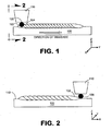
- FIG. 1 is a schematic side view depicting a laser performing manual laser deposition in accordance with an embodiment of a method.
- a substrate 100 is provided upon which is deposited sequential overlapping pulse deposits (e.g., deposits 102, 104) of weld filler.
- the substrate can be formed of 321 Stainless Steel and the weld filler can be formed of 347 Stainless Steel.
- the substrate is a thin-walled substrate that forms a portion of a tube and the weld filler is provided by a wire 106 exhibiting a diameter of approximately 0.020 inches (0.508 mm). Because the substrate is thin walled, the potential for blow though of the substrate is accommodated by parameter selection .
- the wire is placed adjacent to the substrate and a laser 110 is aligned with the weld filler so that a laser beam emitted by the laser illuminates the weld filler.
- the melting area provided by the laser beam need only correspond to the diameter of the weld filler, to further decrease the incidence of defects, the largest possible beam diameter can be selected to provide the greatest amount of operator margin.
- the total heat input provided by the laser beam can be between approximately 20% and approximately 30%, preferably between approximately 23% and approximately 27% of the minimum heat required to fully melt the weld filler and substrate.
- a power setting can be determined by destructive and/or non-destructive evaluation of a test sample.
- FIG. 2 depicts substrate 100 and the deposited material of FIG. 1 as viewed in a plane perpendicular to the direction of traverse of the laser during deposition.
- the weld filler wire is positioned at an intersection of the adjacent deposit 102 and an upper surface 112 of the substrate. In some embodiments, such positioning can result in the deposited weld filler overlapping the adjacent deposit by approximately 40%.
- the laser 110 is a pulsed laser that is manually positioned.
- some embodiments involve the use of a component fixture (not shown) that is used to hold and position the substrate for deposition. It should be noted that the weld surface should be maintained as perpendicular as possible to the laser in order to reduce the amount of z height adjustment during welding.
- an operator traverses the substrate with appropriately positioned weld filler and with pulsed illumination areas of the laser typically at a fixed rate of traversal.
- a pulse rate of between approximately 1 and approximately 6 cycles per millimeter, preferably between approximately 2 and approximately 4 cycles per millimeter can be used.
- a 4 hertz pulse rate results in approximately 80 millimeters of deposition per minute, whereas a 5 hertz pulse rate results in approximately 100 millimeters of deposition per minute.
- FIG. 3 schematically depicts an embodiment of a deposition process that involves melt areas defined by sequential pulses of a laser being applied to a substrate 120 in parallel rows.
- row i includes a sequential application of pulses.
- a first area 122 is illuminated followed by a second area 124, and so on.
- Sequential rows are then illuminated up through the n th row.
- an overlap as depicted in FIG. 2 of approximately 40% is used between rows, e.g., area 126 of the row (i + 1) overlaps approximately 40% of an area in row i .
- bi-directional deposition can occur in some embodiments in contrast to the unidirectional deposition depicted in FIG. 3 .
- an interlayer dry pass is used.
- an embodiment of an interlayer dry pass is depicted schematically in FIG. 4 .
- the interlayer dry pass is placed in the same direction as the initial deposition. Note, however, that in other embodiments, other directions of traverse, e.g., perpendicular to the deposition direction, can be used.
- the sequential overlapping melt areas form parallel rows as in FIG 3 .
- a first melt area 132 is melted followed by a second melt area 134, and so on.
- an overlap of between approximately 70% and approximately 80%, preferably between approximately 73% and 77%, and most preferably approximately 75% of the diameter of a melt area exists between adjacent rows.
- area 136 of the row ( i + 1) overlaps approximately 75% of an area in row i.
- bi-directional illumination can occur in some embodiments in contrast to the unidirectional illumination depicted in FIG. 4 .
- more than one interlayer dry pass can be performed.
- FIG. 5 is a schematic plan view depicting exemplary melt areas (e.g., area 140) formed by an interlayer dry pass with the resulting welding filler and substrate fusion being depicted schematically in FIG. 6 , which is illustrated perpendicular to the direction of traverse.
- the heat input provided by the laser during the interlayer dry pass re-melts the deposited weld filler 142 and the underlying substrate 144, thereby providing near zero defect fusion of the materials.
Landscapes
- Engineering & Computer Science (AREA)
- Physics & Mathematics (AREA)
- Optics & Photonics (AREA)
- Mechanical Engineering (AREA)
- Plasma & Fusion (AREA)
- Laser Beam Processing (AREA)
Abstract
Description
- The disclosure generally relates to welding.
- Automated laser deposition techniques can enable repeatable, near zero defect deposition of material. However, such automated processes tend to be inflexible, in that such processes can be difficult and/or tedious to adapt to welding of components of various shapes, sizes and/or arrangements. Although quite flexible in its adaptability, manual laser deposition tends to suffer from increased defects.
- Methods for performing manual laser deposition are provided. In this regard, an exemplary embodiment of a method comprises: directing a laser beam at a first deposit location of a substrate to re-melt: at least a portion of a first deposit of weld filler, at least a portion of a second deposit of weld filler located at a second deposit location that partially overlaps the first deposit, and at least a portion of the substrate.
- Another exemplary embodiment of a method comprises: positioning weld filler in proximity to a substrate; directing a laser beam toward the weld filler such that a first portion of the weld filler melts and forms a first deposit on a substrate in a first deposit location; repositioning the weld filler such that the weld filler is located adjacent to the first deposit location; subsequently directing the laser beam toward the weld filler located adjacent to the first deposit location such that a second portion of the weld filler melts and forms a second deposit on the substrate in a second deposit location, the second deposit overlying at least a portion of the first deposit; and directing the laser beam at the first location such that at least a portion of the first deposit, at least a portion of the second deposit, and at least a portion of the substrate are melted without depositing additional weld filler.
- Another exemplary embodiment of a method comprises: sequentially depositing at least partially overlapping deposits of weld filler on a substrate using a pulsed laser beam of a manually controlled laser, the pulsed laser beam providing a total heat input of between approximately 20% and approximately 30% of the minimum heat required to melt the weld filler and the substrate during the depositing; and re-melting, with the pulsed laser beam, in an overlapping fashion.
- Other systems, methods, features and/or advantages of this disclosure will be or may become apparent to one with skill in the art upon examination of the following drawings and detailed description. It is intended that all such additional systems, methods, features and/or advantages be included within this description and be within the scope of the present disclosure.
- Many aspects of the disclosure can be better understood with reference to the following drawings. The components in the drawings are not necessarily to scale. Moreover, in the drawings, like reference numerals designate corresponding parts throughout the several views.
-
FIG. 1 is a schematic side view depicting a laser performing manual laser deposition in accordance with an embodiment. -
FIG. 2 is a schematic side view of the embodiment ofFIG. 1 , as viewed parallel to the direction of traverse of the laser. -
FIG. 3 is a schematic plan view depicting sequential melting areas by a laser performing material deposition in accordance with another embodiment. -
FIG. 4 is a schematic plan view of a substrate and representative sequential melting areas by a laser performing an interlayer dry pass in accordance with another embodiment. -
FIG. 5 is a schematic plan view of representative sequential melting areas by a laser performing an interlayer dry pass in accordance with another embodiment. -
FIG. 6 is a schematic side view of the embodiment ofFIG. 5 showing material deposition and extent of melt penetration into the substrate. - As will be described in detail here, methods for performing manual laser deposition are provided. In this regard, some embodiments can provide near zero defect results despite using a manual laser, i.e., a laser that is manually controlled by an operator. Notably, an exemplary embodiment involves increasing an amount of overlap between areas that are sequentially melted by the laser in order to improve heat penetration through the deposited material and into the substrate. The use of high-density overlap enables a low energy, yet highly focused, laser to deposit material on substrates, including thin-walled substrates that may otherwise be subject to warping during other heating techniques. As used herein, thin-walled refers to a substrate of approximately 0.039 inches (1 mm) in thickness or less.
-
FIG. 1 is a schematic side view depicting a laser performing manual laser deposition in accordance with an embodiment of a method. As shown inFIG. 1 , asubstrate 100 is provided upon which is deposited sequential overlapping pulse deposits (e.g.,deposits 102, 104) of weld filler. In this figure, an approximate 75% pulse overlap is controlled by parameter selection. By way of example, the substrate can be formed of 321 Stainless Steel and the weld filler can be formed of 347 Stainless Steel. In this embodiment, the substrate is a thin-walled substrate that forms a portion of a tube and the weld filler is provided by awire 106 exhibiting a diameter of approximately 0.020 inches (0.508 mm). Because the substrate is thin walled, the potential for blow though of the substrate is accommodated by parameter selection . - In order to perform deposition of the weld filler, the wire is placed adjacent to the substrate and a
laser 110 is aligned with the weld filler so that a laser beam emitted by the laser illuminates the weld filler. Although the melting area provided by the laser beam need only correspond to the diameter of the weld filler, to further decrease the incidence of defects, the largest possible beam diameter can be selected to provide the greatest amount of operator margin. - In order to melt the weld filler, power of the laser is adjusted in order to melt the wire and corresponding adjacent portion of the substrate in order to provide for adequate fusion of the weld filler to the substrate. By way of example, the total heat input provided by the laser beam can be between approximately 20% and approximately 30%, preferably between approximately 23% and approximately 27% of the minimum heat required to fully melt the weld filler and substrate. In practice, such a power setting can be determined by destructive and/or non-destructive evaluation of a test sample.
- Positioning of the weld filler with respect to a previously deposited row of material deposits is shown schematically in
FIG. 2 . In particular,FIG. 2 depictssubstrate 100 and the deposited material ofFIG. 1 as viewed in a plane perpendicular to the direction of traverse of the laser during deposition. Note that the weld filler wire is positioned at an intersection of theadjacent deposit 102 and anupper surface 112 of the substrate. In some embodiments, such positioning can result in the deposited weld filler overlapping the adjacent deposit by approximately 40%. - In the embodiment of
FIGS. 1 and 2 , thelaser 110 is a pulsed laser that is manually positioned. In this regard, some embodiments involve the use of a component fixture (not shown) that is used to hold and position the substrate for deposition. It should be noted that the weld surface should be maintained as perpendicular as possible to the laser in order to reduce the amount of z height adjustment during welding. - Once suitably positioned, an operator traverses the substrate with appropriately positioned weld filler and with pulsed illumination areas of the laser typically at a fixed rate of traversal. In this regard, a pulse rate of between approximately 1 and approximately 6 cycles per millimeter, preferably between approximately 2 and approximately 4 cycles per millimeter can be used. Notably at 3 cycles per millimeter, a 4 hertz pulse rate results in approximately 80 millimeters of deposition per minute, whereas a 5 hertz pulse rate results in approximately 100 millimeters of deposition per minute.
-
FIG. 3 schematically depicts an embodiment of a deposition process that involves melt areas defined by sequential pulses of a laser being applied to asubstrate 120 in parallel rows. Specifically, row i includes a sequential application of pulses. In this case, afirst area 122 is illuminated followed by asecond area 124, and so on. Sequential rows are then illuminated up through the n th row. Notably, an overlap as depicted inFIG. 2 of approximately 40% is used between rows, e.g.,area 126 of the row (i + 1) overlaps approximately 40% of an area in row i. Note also that bi-directional deposition can occur in some embodiments in contrast to the unidirectional deposition depicted inFIG. 3 . - In order to ensure adequate fusion of the weld filler and substrate, an interlayer dry pass is used. In this regard, an embodiment of an interlayer dry pass is depicted schematically in
FIG. 4 . As shown inFIG. 4 , the interlayer dry pass is placed in the same direction as the initial deposition. Note, however, that in other embodiments, other directions of traverse, e.g., perpendicular to the deposition direction, can be used. - In this embodiment, the sequential overlapping melt areas form parallel rows as in
FIG 3 . In this case, afirst melt area 132 is melted followed by asecond melt area 134, and so on. However, in contrast to applying the deposition rows, an overlap of between approximately 70% and approximately 80%, preferably between approximately 73% and 77%, and most preferably approximately 75% of the diameter of a melt area exists between adjacent rows. For instance, inFIG. 4 ,area 136 of the row (i + 1) overlaps approximately 75% of an area in row i. Note also that bi-directional illumination can occur in some embodiments in contrast to the unidirectional illumination depicted inFIG. 4 . In some embodiments, more than one interlayer dry pass can be performed. -
FIG. 5 is a schematic plan view depicting exemplary melt areas (e.g., area 140) formed by an interlayer dry pass with the resulting welding filler and substrate fusion being depicted schematically inFIG. 6 , which is illustrated perpendicular to the direction of traverse. As shown inFIG. 6 , the heat input provided by the laser during the interlayer dry pass re-melts the depositedweld filler 142 and theunderlying substrate 144, thereby providing near zero defect fusion of the materials. - It should be emphasized that the above-described embodiments are merely possible examples of implementations set forth for a clear understanding of the principles of this disclosure. Many variations and modifications may be made to the above-described embodiments without departing substantially from the principles of the disclosure. All such modifications and variations are intended to be included herein within the scope of this disclosure and protected by the accompanying claims.
Claims (15)
- A method for performing manual laser deposition comprising:positioning weld filler in proximity to a substrate;directing a laser beam toward the weld filler such that a first portion of the weld filler melts and forms a first deposit on a substrate in a first deposit location;repositioning the weld filler such that the weld filler is located adjacent to the first deposit location;subsequently directing the laser beam toward the weld filler located adjacent to the first deposit location such that a second portion of the weld filler melts and forms a second deposit on the substrate in a second deposit location, the second deposit overlying at least a portion of the first deposit; anddirecting the laser beam at the first location such that at least a portion of the first deposit, at least a portion of the second deposit, and at least a portion of the substrate are melted without depositing additional weld filler.
- The method of claim 1, wherein:the weld filler is provided by a weld filler wire; andthe repositioning comprises locating the weld filler wire at an intersection of the first deposit and the substrate for forming the second deposit.
- The method of claim 1 or 2, further comprising directing the laser beam to perform a dry pass such that at least a portion of the first deposit, at least a portion of the second deposit and at least a portion of the substrate are melted.
- The method of claim 3, wherein, in directing the laser beam to perform the dry pass, each sequentially applied melt area overlaps an immediately preceding melt area by at least 70% of the diameter of the immediately preceding melt area.
- The method of claim 4, wherein, in directing the laser beam to perform the dry pass, each sequentially applied melt area overlaps an immediately preceding melt area by no more than 80% of the diameter of the immediately preceding melt area.
- The method of any preceding claim, wherein the laser beam exhibits a fixed traverse with a pulse rate of approximately 3 cycles per millimeter.
- The method of any preceding claim, wherein the substrate exhibits a thickness of no greater than approximately 0.039 inches (1 mm) at the first deposit location prior to forming the first deposit.
- The method of any preceding claim, wherein the laser beam provides a total heat input of at least approximately 20% of the minimum heat required to melt the weld filler and the substrate during the depositing steps.
- The method of any preceding claim, wherein the substrate is a thin-walled substrate.
- The method of any preceding claim, wherein:the weld filler is deposited in sequential rows of deposits; andthe re-melting is performed by sequential rows of overlapping melting areas of the laser beam.
- The method of claim 10, wherein adjacent ones of the overlapping melting areas formed during the re-melting overlap by between approximately 70% and approximately 80% of the diameter of one of the melting areas.
- The method of any preceding claim, wherein:the substrate is formed of 321 Stainless Steel; andthe weld filler is formed of 347 Stainless Steel.
- The method of any preceding claim, wherein the substrate is tubular.
- The method of claim 13, wherein the substrate has a maximum wall thickness of between approximately 1 millimeter at a location at which the weld filler is deposited prior to the depositing.
- The method of any preceding claim, wherein the laser beam is a pulsed laser beam and exhibits a pulse rate of between approximately 1 cycle and approximately 6 cycles per millimeter.
Applications Claiming Priority (1)
| Application Number | Priority Date | Filing Date | Title |
|---|---|---|---|
| US11/782,781 US7847208B2 (en) | 2007-07-25 | 2007-07-25 | Methods for performing manual laser deposition |
Publications (2)
| Publication Number | Publication Date |
|---|---|
| EP2022596A1 true EP2022596A1 (en) | 2009-02-11 |
| EP2022596B1 EP2022596B1 (en) | 2012-06-13 |
Family
ID=39942713
Family Applications (1)
| Application Number | Title | Priority Date | Filing Date |
|---|---|---|---|
| EP08252424A Ceased EP2022596B1 (en) | 2007-07-25 | 2008-07-16 | Method of performing a manual laser deposition using a weld filler |
Country Status (2)
| Country | Link |
|---|---|
| US (1) | US7847208B2 (en) |
| EP (1) | EP2022596B1 (en) |
Cited By (1)
| Publication number | Priority date | Publication date | Assignee | Title |
|---|---|---|---|---|
| FR3046740A1 (en) * | 2016-01-18 | 2017-07-21 | Snecma | PROCESS FOR RECHARGING OR MANUFACTURING A METAL PIECE |
Families Citing this family (1)
| Publication number | Priority date | Publication date | Assignee | Title |
|---|---|---|---|---|
| JP2010131639A (en) * | 2008-12-05 | 2010-06-17 | Mitsubishi Heavy Ind Ltd | Clad welding method |
Citations (8)
| Publication number | Priority date | Publication date | Assignee | Title |
|---|---|---|---|---|
| US4564736A (en) * | 1984-05-07 | 1986-01-14 | General Electric Company | Industrial hand held laser tool and laser system |
| JPS62183987A (en) * | 1986-02-07 | 1987-08-12 | Nippon Kokan Kk <Nkk> | Laser beam cladding method |
| EP0558870A1 (en) * | 1992-03-02 | 1993-09-08 | Sulzer Innotec Ag | Free welding of metal structures casing a laser |
| JPH11347774A (en) * | 1998-06-11 | 1999-12-21 | Amada Co Ltd | Handy laser beam head for yag laser |
| US6342688B1 (en) * | 2000-06-09 | 2002-01-29 | Cti, Inc. | Method for preparing iridium crucibles for crystal growth |
| US20030094259A1 (en) * | 2001-11-20 | 2003-05-22 | Siedal David S. | Method and apparatus for free-forging of metal structures |
| JP2005254317A (en) * | 2004-03-15 | 2005-09-22 | Nippon Steel Corp | Self-fluxing alloy coating method and apparatus, continuous casting mold using the same, and manufacturing method thereof |
| EP1959095A2 (en) * | 2007-02-14 | 2008-08-20 | United Technologies Corporation | Dimensional restoration of stator inner shrouds |
Family Cites Families (12)
| Publication number | Priority date | Publication date | Assignee | Title |
|---|---|---|---|---|
| US4665294A (en) | 1986-03-27 | 1987-05-12 | Westinghouse Electric Corp. | Method of welding aluminum alloys |
| AU2436192A (en) * | 1991-08-09 | 1993-03-02 | Board Of Regents, The University Of Texas System | High temperature wet oxidation using sintered separators |
| US6333484B1 (en) | 2000-03-17 | 2001-12-25 | Chromalloy Gas Turbine Corporation | Welding superalloy articles |
| US6495793B2 (en) | 2001-04-12 | 2002-12-17 | General Electric Company | Laser repair method for nickel base superalloys with high gamma prime content |
| US6884964B2 (en) | 2003-01-09 | 2005-04-26 | General Electric Company | Method of weld repairing a component and component repaired thereby |
| US7509734B2 (en) | 2003-03-03 | 2009-03-31 | United Technologies Corporation | Repairing turbine element |
| US7146725B2 (en) | 2003-05-06 | 2006-12-12 | Siemens Power Generation, Inc. | Repair of combustion turbine components |
| US7038162B2 (en) | 2003-11-13 | 2006-05-02 | Honeywell International, Inc. | Hand-held laser welding wand filler media delivery systems and methods |
| JP3992106B2 (en) | 2004-01-16 | 2007-10-17 | 独立行政法人 宇宙航空研究開発機構 | Drive method and drive mechanism using interfacial tension difference convection generated in two fluids with interface |
| US20050205415A1 (en) | 2004-03-19 | 2005-09-22 | Belousov Igor V | Multi-component deposition |
| US7404986B2 (en) | 2004-05-07 | 2008-07-29 | United Technologies Corporation | Multi-component deposition |
| US7094988B1 (en) | 2005-04-18 | 2006-08-22 | Honeywell International, Inc. | Laser welding heat treat process |
-
2007
- 2007-07-25 US US11/782,781 patent/US7847208B2/en not_active Expired - Fee Related
-
2008
- 2008-07-16 EP EP08252424A patent/EP2022596B1/en not_active Ceased
Patent Citations (8)
| Publication number | Priority date | Publication date | Assignee | Title |
|---|---|---|---|---|
| US4564736A (en) * | 1984-05-07 | 1986-01-14 | General Electric Company | Industrial hand held laser tool and laser system |
| JPS62183987A (en) * | 1986-02-07 | 1987-08-12 | Nippon Kokan Kk <Nkk> | Laser beam cladding method |
| EP0558870A1 (en) * | 1992-03-02 | 1993-09-08 | Sulzer Innotec Ag | Free welding of metal structures casing a laser |
| JPH11347774A (en) * | 1998-06-11 | 1999-12-21 | Amada Co Ltd | Handy laser beam head for yag laser |
| US6342688B1 (en) * | 2000-06-09 | 2002-01-29 | Cti, Inc. | Method for preparing iridium crucibles for crystal growth |
| US20030094259A1 (en) * | 2001-11-20 | 2003-05-22 | Siedal David S. | Method and apparatus for free-forging of metal structures |
| JP2005254317A (en) * | 2004-03-15 | 2005-09-22 | Nippon Steel Corp | Self-fluxing alloy coating method and apparatus, continuous casting mold using the same, and manufacturing method thereof |
| EP1959095A2 (en) * | 2007-02-14 | 2008-08-20 | United Technologies Corporation | Dimensional restoration of stator inner shrouds |
Cited By (1)
| Publication number | Priority date | Publication date | Assignee | Title |
|---|---|---|---|---|
| FR3046740A1 (en) * | 2016-01-18 | 2017-07-21 | Snecma | PROCESS FOR RECHARGING OR MANUFACTURING A METAL PIECE |
Also Published As
| Publication number | Publication date |
|---|---|
| EP2022596B1 (en) | 2012-06-13 |
| US20090026174A1 (en) | 2009-01-29 |
| US7847208B2 (en) | 2010-12-07 |
Similar Documents
| Publication | Publication Date | Title |
|---|---|---|
| CN103163180B (en) | Nondestructive detection system | |
| Javadi et al. | Continuous monitoring of an intentionally-manufactured crack using an automated welding and in-process inspection system | |
| CN104334349B (en) | Sheet metal part with welding recess and method of forming same | |
| US8373089B2 (en) | Combustion cap effusion plate laser weld repair | |
| CN107000119A (en) | Method and apparatus for two workpiece to be attached in overlapping junction point | |
| JP2014195822A5 (en) | ||
| DE102015016513B4 (en) | Online process monitoring and online process control in the method for form-fitting or material-locking connection of at least two components by a joining process using a radiometric device | |
| CN106112207A (en) | Gas metal-arc welding 3D increases material repair apparatus and method for repairing and mending | |
| US20190381601A1 (en) | Laser welding method and welded structure | |
| CN106141374A (en) | Non-consumable gas shielded arc welding 3D increases material repair apparatus and method for repairing and mending | |
| US7847208B2 (en) | Methods for performing manual laser deposition | |
| CN105171234B (en) | Robotic laser welds defocusing amount automatic regulating apparatus and its automatic adjusting method | |
| CN106932415B (en) | A composite non-destructive testing device and method dedicated to laser welding joints | |
| CN103264225A (en) | Laser butt welding process parameter optimization method and device | |
| US20200361033A1 (en) | Tack welding method and tack welding apparatus | |
| JPH0729210B2 (en) | Laser welding method | |
| Kumar | Defects associated with welding techniques and their detection methods | |
| WO2021106400A1 (en) | Weld inspecting device | |
| JP6385763B2 (en) | Laser welding apparatus and laser welding method | |
| JP2014024068A (en) | Bead inspection method in laser welding and laser welding method | |
| DE102009052529B4 (en) | Method for monitoring the quality of a connecting seam and device for laser welding or laser soldering | |
| Fixemer et al. | Seam guided laser remote welding with automated gap bridging: Increased process windows by online recognition of gap situation | |
| EP3417283B1 (en) | Metrology apparatus and metrology method | |
| JP2005138126A (en) | Welding system | |
| Delany et al. | Advanced joining processes for repair in nuclear power plants |
Legal Events
| Date | Code | Title | Description |
|---|---|---|---|
| PUAI | Public reference made under article 153(3) epc to a published international application that has entered the european phase |
Free format text: ORIGINAL CODE: 0009012 |
|
| AK | Designated contracting states |
Kind code of ref document: A1 Designated state(s): AT BE BG CH CY CZ DE DK EE ES FI FR GB GR HR HU IE IS IT LI LT LU LV MC MT NL NO PL PT RO SE SI SK TR |
|
| AX | Request for extension of the european patent |
Extension state: AL BA MK RS |
|
| 17P | Request for examination filed |
Effective date: 20090514 |
|
| 17Q | First examination report despatched |
Effective date: 20090615 |
|
| AKX | Designation fees paid |
Designated state(s): DE GB |
|
| GRAP | Despatch of communication of intention to grant a patent |
Free format text: ORIGINAL CODE: EPIDOSNIGR1 |
|
| RTI1 | Title (correction) |
Free format text: METHOD OF PERFORMING A MANUAL LASER DEPOSITION USING A WELD FILLER |
|
| GRAS | Grant fee paid |
Free format text: ORIGINAL CODE: EPIDOSNIGR3 |
|
| GRAA | (expected) grant |
Free format text: ORIGINAL CODE: 0009210 |
|
| AK | Designated contracting states |
Kind code of ref document: B1 Designated state(s): DE GB |
|
| REG | Reference to a national code |
Ref country code: GB Ref legal event code: FG4D |
|
| REG | Reference to a national code |
Ref country code: DE Ref legal event code: R096 Ref document number: 602008016289 Country of ref document: DE Effective date: 20120809 |
|
| PLBE | No opposition filed within time limit |
Free format text: ORIGINAL CODE: 0009261 |
|
| STAA | Information on the status of an ep patent application or granted ep patent |
Free format text: STATUS: NO OPPOSITION FILED WITHIN TIME LIMIT |
|
| 26N | No opposition filed |
Effective date: 20130314 |
|
| REG | Reference to a national code |
Ref country code: DE Ref legal event code: R097 Ref document number: 602008016289 Country of ref document: DE Effective date: 20130314 |
|
| REG | Reference to a national code |
Ref country code: DE Ref legal event code: R082 Ref document number: 602008016289 Country of ref document: DE Representative=s name: SCHMITT-NILSON SCHRAUD WAIBEL WOHLFROM PATENTA, DE |
|
| REG | Reference to a national code |
Ref country code: DE Ref legal event code: R082 Ref document number: 602008016289 Country of ref document: DE Representative=s name: SCHMITT-NILSON SCHRAUD WAIBEL WOHLFROM PATENTA, DE Ref country code: DE Ref legal event code: R081 Ref document number: 602008016289 Country of ref document: DE Owner name: UNITED TECHNOLOGIES CORP. (N.D.GES.D. STAATES , US Free format text: FORMER OWNER: UNITED TECHNOLOGIES CORP. (N.D.GES.D. STAATES DELAWARE), HARTFORD, CONN., US |
|
| REG | Reference to a national code |
Ref country code: DE Ref legal event code: R081 Ref document number: 602008016289 Country of ref document: DE Owner name: RAYTHEON TECHNOLOGIES CORPORATION (N.D.GES.D.S, US Free format text: FORMER OWNER: UNITED TECHNOLOGIES CORP. (N.D.GES.D. STAATES DELAWARE), FARMINGTON, CONN., US |
|
| P01 | Opt-out of the competence of the unified patent court (upc) registered |
Effective date: 20230519 |
|
| PGFP | Annual fee paid to national office [announced via postgrant information from national office to epo] |
Ref country code: GB Payment date: 20230620 Year of fee payment: 16 |
|
| PGFP | Annual fee paid to national office [announced via postgrant information from national office to epo] |
Ref country code: DE Payment date: 20230620 Year of fee payment: 16 |
|
| REG | Reference to a national code |
Ref country code: DE Ref legal event code: R119 Ref document number: 602008016289 Country of ref document: DE |
|
| GBPC | Gb: european patent ceased through non-payment of renewal fee |
Effective date: 20240716 |
|
| PG25 | Lapsed in a contracting state [announced via postgrant information from national office to epo] |
Ref country code: DE Free format text: LAPSE BECAUSE OF NON-PAYMENT OF DUE FEES Effective date: 20250201 |
|
| PG25 | Lapsed in a contracting state [announced via postgrant information from national office to epo] |
Ref country code: GB Free format text: LAPSE BECAUSE OF NON-PAYMENT OF DUE FEES Effective date: 20240716 |