EP2022320A1 - Baummesser - Google Patents
Baummesser Download PDFInfo
- Publication number
- EP2022320A1 EP2022320A1 EP07113882A EP07113882A EP2022320A1 EP 2022320 A1 EP2022320 A1 EP 2022320A1 EP 07113882 A EP07113882 A EP 07113882A EP 07113882 A EP07113882 A EP 07113882A EP 2022320 A1 EP2022320 A1 EP 2022320A1
- Authority
- EP
- European Patent Office
- Prior art keywords
- fixed
- lopper
- outer tube
- inner tube
- rotatable
- Prior art date
- Legal status (The legal status is an assumption and is not a legal conclusion. Google has not performed a legal analysis and makes no representation as to the accuracy of the status listed.)
- Granted
Links
Images


Classifications
-
- A—HUMAN NECESSITIES
- A01—AGRICULTURE; FORESTRY; ANIMAL HUSBANDRY; HUNTING; TRAPPING; FISHING
- A01G—HORTICULTURE; CULTIVATION OF VEGETABLES, FLOWERS, RICE, FRUIT, VINES, HOPS OR SEAWEED; FORESTRY; WATERING
- A01G3/00—Cutting implements specially adapted for horticultural purposes; Delimbing standing trees
- A01G3/02—Secateurs; Flower or fruit shears
- A01G3/025—Secateurs; Flower or fruit shears having elongated or extended handles
- A01G3/0255—Tree pruners, i.e. pruning shears carried at the end of a pole
Definitions
- the present invention relates to gardening tools, and more particularly, to a lopper for pruning tree branches and leaves lying high.
- a lopper is typically implemented to prune tree branches and leaves lying high, which is composed of a slender rod and a pair of shears mounted on the top of the rod.
- One general objective of loppers is to facilitate effort-saving operation.
- various mechanisms employing linkages and levers are applied to loppers, such as those disclosed in US Patent 6,178,644 and US Patent 4,649,646 .
- the conventional lopper has the complexly structured and bulky shears mounted on the top of the rod, it would be difficult for a user to maintain the balance of the lopper while holding and operating the same.
- the heavy weight of the shears of the conventional lopper substantially burdens the user.
- the intricate linkages and ropes settled around the shears are liable to get tangled with luxuriant branches and leaves where a user tries to stretch the shears through, therefore resulting in retarded efficiency of pruning.
- the rod of the '315 lopper has a fixed length which is not extendable, if a user wants to prune branches and leaves at a relatively higher location, a ladder has to be implemented to lift the user and this may disadvantageously render inconvenience and danger to the user.
- the present invention has been accomplished under these circumstances in view. It is one objective of the present invention to provide a lopper that facilitates effort-saving pruning and has a rod with a length, which is adjustable according to the altitude of the branches and leaves to be pruned.
- the lopper comprises a slender rod and a pruning means mounted on a top of the rod.
- the slender rod is composed of an inner tube and an outer tube telescoped mutually such that the inner tube is shiftable in the outer tube for changing the length as it jutting out from the outer tube.
- An extension-control unit is provided at the border region between the inner tube and the outer tube for positioning the inner tube.
- a fist actuating unit and a second actuating unit are provided at an outer surface of the outer tube.
- the fist and second actuating units are connected with the pruning means through a first rope, a second rope and a third rope so that when a user pulls the first or second actuating unit, a shear assembly of the pruning means can be closed to cut branches and leaves of plants.
- the disclosed lopper has the advantages of effort-saving operation, simplified construction, light weight, easy gripping, easy controlling, and adjustable operational angle of the shear assembly. Additionally, the lopper of the present invention allows a user to adjust the extending length of the handling rod according to the altitude of the branches and leaves to be pruned.
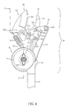
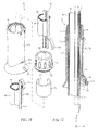
- the lopper of the present invention primarily comprises a slender rod 10 and a pruning mechanism 20 mounted on a top of the slender rod 10.
- the slender rod 10 includes an apparently visible outer tube 60, an inner tube 61 shiftably telescoped inside the outer tube 60, an extension-control unit 65 provided at a border region between the outer and inner tubes 60, 61, a first actuating unit 70 deposited at the outer tube 60 and a second actuating unit 80 deposited at a bottom of the outer tube 60.
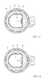
- the pruning mechanism 20 comprises three parts, which are a drum 21, an axial wheel 40 and a shear assembly 50, wherein the drum 21 is constructed form combining a fixed portion 22 and a rotatable portion 30 face to face.
- the fixed portion 22 is substantially shaped as a round box for providing a round space 23 therein.
- a combining portion 24 radially extends outward from the fixed portion 22 for being inserted into a top of the inner tube 61 of the slender rod 10.
- the rotatable portion 30 is substantially shaped as a round box for providing a round space 31 therein (as shown in FIG. 7 ).
- a combining portion 32 radially extends outward from the rotatable portion 30 for being combined with the shear assembly 50.
- the fixed portion 22 and the rotatable portion 30 are coaxially combined so that the axial wheel 40 can be accommodated in the round spaces 23, 31.
- a manual-loosened bolt assembly 25 passes through the fixed portion 22, the rotatable portion 30, a center of the axial wheel 40 to combine the fixed portion 22 and the rotatable portion 30 together such that the axial wheel 40 can rotate about the bolt assembly 25.
- the axial wheel 40 includes a first reel 41 and a second reel 42 which are configured coaxially.
- the first reel 41 has a diameter greater than that of the second reel 42.
- a first rope 11 has one end thereof fastened to the first reel 41 and is then wound around the first reel 41. Afterward, an opposite end of the first rope 11 goes into the inner tube 61 of the slender rod 10.
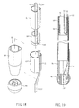
- the shear assembly 50 comprises a fixed blade 51, a movable blade 52, a linkage 53 and a flexible linking component 54.
- the fixed blade 51 has an integral structure that includes a block portion 511, a pivot portion 512 and a combining portion 513, wherein the combining portion 513 is fixed to the combining portion 32 of the rotatable portion 30 by means of a fastening component 514.
- the movable blade 52 has an integral structure that includes a blade portion 521, a pivot portion 522 and a driving portion 524. The movable blade 52 is set in the combining portion 32 of the rotatable portion 30 abutting one side of the fixed blade 51 such that the pivot portion 522 thereof abuts the pivot portion 512 of the fixed blade 51.
- a pin 523 passing through the two pivot portions 512, 522 can be fixed to the combining portion 32 of the rotatable portion 30 so that the movable blade 52 can rotate about the pin 523.
- the linkage 53 connected with the pivot portion 512 of the fixed blade 51 and the driving portion 524 of the movable blade 52 is a two-piece linkage.
- a first link 531 of the linkage 53 has one end thereof rotatably fastened to the pivot portion 512 of the fixed blade 51 by a pin 532 and has an opposite end thereof equipped with a pulley 533.
- a second link 534 of the linkage 53 has one end thereof rotatably fastened to the first link 531 by a pin 535 and has an opposite end thereof rotatably fastened to the driving portion 524 of the movable blade 52 by a pin 536.
- the flexible linking component 54 wound around the pulley 533 has one end thereof passing through a preformed hole 33 preset on the rotatable portion 30 and is then fixed at the second reel 42 of the axial wheel 40. Then an opposite end of the flexible linking component 54 is fixed at a positioning member 34 outside the rotatable portion 30.
- a returning spring 59 is provided between the pivot portion 522 of the movable blade 52 and the rotatable portion 30 for exerting a recoiling force on the movable blade 52 so that the blade portion 521 of the movable blade 52 is normally separated from the fixed blade 51.
- serrations 26, 30 are formed at facing edges of the fixed portion 22 and the rotatable portion 30, respectively, so that after being fastened by the bolt assembly 25, the fixed portion 22 and the rotatable portion 30 are braked mutually and the rotatable portion 30 and the shears thereon are secured from unintentional rotating.
- the combination between the fixed portion 22 and the rotatable portion 30 can be tightened or loosened by manually screwing a loosen nut 251 of the bolt assembly 25.
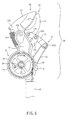
- the nut 251 can be slightly loosened to cause the fixed portion 22 and the rotatable portion 30 to slightly separate such that the rotatable portion 30 can be rotate to turn the fixed blade 51 and the movable blade 52 of the shear assembly 50 to face the slender rod 10 for safe storage that facilitates preventing people from getting hurt by the shears.
- the adjustable bolt assembly 25 as previously described also suggests that the shear assembly 50 of the present invention can be re-oriented to avail a desired operational angle thereof. By conducting the above operation, an angular magnitude between the shear assembly 50 and the slender rod 10 can be adjusted and then fixed.
- the fixed portion 22 of the shear assembly 50 has the combining portion 24 radially extends outward therefrom to be inserted into the top of the inner tube 61.
- a pulley set 62 that includes a first pulley 621 and a second pulley 622 may be movably settled in the inner tube 61.
- the first rope 11 of the shear assembly 50 is wound around the first pulley 621 and has an open end fixed to the combining portion 24.
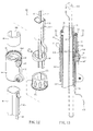
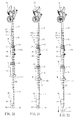
- the extension-control unit 65 provided at the border region between the outer and inner tubes 60, 61 is further illustrated.
- the extension-control unit 65 comprises a fixed member 66, a rotatable member 67 and a C-shaped inner ring 68.
- the fixed member 66 is fixed outside the top of the outer tube 60 and has an intrusive portion 661 for being retained with the top of the outer tube 60.
- the C-shaped inner ring 68 is attached on the inner tube 61.
- the rotatable member 67 is mounted around the C-shaped inner ring 68 and has an externally threaded portion 671 at the bottom thereof combined with an interiorly threaded portion 664 at a top of the fixed member 66.
- a prominent packing portion 672 is provided at an inner wall of the rotatable member 67 to be positioned in an opening 682 of the C-shaped inner ring 68.
- the first actuating unit 70 comprises a fixed member 71, a rotatable member 72 and a C-shaped inner ring 73.
- the fixed member 71 sheathes around the outer tube 60 and has an intrusive portion 711 for receiving the C-shaped inner ring 73.
- the C-shaped inner ring 73 is attached on the outer tube 60.
- the rotatable member 72 is mounted around the C-shaped inner ring 73 and has an externally threaded portion 721 at the bottom thereof combined with an interiorly threaded portion 712 at a top of the fixed member 71.
- a prominent packing portion 722 is provided at an inner wall of the rotatable member 72 to be positioned in an opening 731 of the C-shaped inner ring 73. While the rotatable member 72 can be rotated, the opening 731 of the C-shaped inner ring 73 substantially limits the displacement of the packing portion 722. Thus, the rotatable angle of the rotatable member 72 is limited. Therefore, when the rotatable member 72 is rotated along one direction, the packing portion 722 abuts against the surface of the outer tube 60, so that the first actuating unit 70 can be fixed outside the outer tube 60 and can not be pulled any more.
- the packing portion 722 is drawn apart from the surface of the outer tube 60, so that the first actuating unit 70 can be pulled to shift along the outer tube 60 to and fro for a predetermined distance.
- the second actuating unit 80 comprises a fixed member 81 and an actuating member 82.
- the fixed member 81 is snugly fixed around the bottom of the outer tube 60.
- the actuating member 82 is coupled with the bottom of the fixed member 81.
- a second retaining piece 64 is provided at a bottom of the inner tube 61.
- the disclosed lopper further comprises a second rope 12 and a third rope 13.
- the second rope 12 is wound around the second pulley 622 of the pulley set 62, and then two ends of the second rope 12 extend downward parallelly.
- the end 121 of the second rope 12 stretches into the inner tube 61; passes around the second retaining piece 64 at the bottom of the inner tube 61; and goes upward along the outer wall of the inner tube 61 to be fixed at a first wall hole 655 of the fixed member 66 of the extension-control unit 65.
- the other end 122 of the second rope 12 stretches into the inner tube 61 for a predetermined distance; passes through a wall hole 611 of the inner tube 61 and a second wall hole 666 of the fixed member 66 of the extension-control unit 65; turns inward again through a third wall hole 667; goes downward along a groove 601 at the surface of the outer tube 60 to the first actuating unit 70; passes through a first wall hole 713 of the fixed member 71; and is fixed at a second wall hole 714.
- the third rope 13 is arranged along the groove 601 at the surface of the outer tube 60.
- One end 131 of the third rope 13 passes through the first wall hole 713 of the fixed member 71 of the first actuating unit 70 and is fixed at a third wall hole 715.
- An opposite end 132 of the third rope 13 is fixed at the actuating member 82 of the second actuating unit 80.
- a user can implement either the first actuating unit 70 or the second actuating unit 80 to operate the shear assembly 50 according to his/her operational convenience.
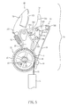
- a basic length of the slender rod 10 is composed of a total length of the outer tube 60 and a length of a segment of the inner tube 61 currently jutting out from the outer tube 60.
- the inner tube 61 is extremely pulled out from the outer tube 60.
- a maximum length of the slender rod 10 is composed of a total length of the outer tube 60 and a length of a segment of the inner tube 61 currently jutting out from the outer tube 60.
- the second rope 12 can accommodate itself thereto, so that the shear assembly 50 can be always controlled by the fist and second actuating units 70, 80.
- the second retaining piece 64 of the inner tube 61 provides a retaining recess 641 while the intrusive portion 661 of the fixed member 66 of the extension-control unit 65 provides a retaining protrusion 662 as shown in Figure 12 .
- the retaining recess 641 of the second retaining piece 64 is coupled with the retaining protrusion 662 of the extension-control unit 65 so that the inner tube can be secured and free from leaving the outer tube 60.
Landscapes
- Life Sciences & Earth Sciences (AREA)
- Biodiversity & Conservation Biology (AREA)
- Ecology (AREA)
- Forests & Forestry (AREA)
- Environmental Sciences (AREA)
- Scissors And Nippers (AREA)
- Harvesting Machines For Specific Crops (AREA)
- Protection Of Plants (AREA)
- Supports For Plants (AREA)
- Pharmaceuticals Containing Other Organic And Inorganic Compounds (AREA)
- Acyclic And Carbocyclic Compounds In Medicinal Compositions (AREA)
Priority Applications (3)
| Application Number | Priority Date | Filing Date | Title |
|---|---|---|---|
| DE602007003346T DE602007003346D1 (de) | 2007-08-06 | 2007-08-06 | Baummesser |
| EP07113882A EP2022320B1 (de) | 2007-08-06 | 2007-08-06 | Baummesser |
| AT07113882T ATE448682T1 (de) | 2007-08-06 | 2007-08-06 | Baummesser |
Applications Claiming Priority (1)
| Application Number | Priority Date | Filing Date | Title |
|---|---|---|---|
| EP07113882A EP2022320B1 (de) | 2007-08-06 | 2007-08-06 | Baummesser |
Publications (2)
| Publication Number | Publication Date |
|---|---|
| EP2022320A1 true EP2022320A1 (de) | 2009-02-11 |
| EP2022320B1 EP2022320B1 (de) | 2009-11-18 |
Family
ID=38879069
Family Applications (1)
| Application Number | Title | Priority Date | Filing Date |
|---|---|---|---|
| EP07113882A Not-in-force EP2022320B1 (de) | 2007-08-06 | 2007-08-06 | Baummesser |
Country Status (3)
| Country | Link |
|---|---|
| EP (1) | EP2022320B1 (de) |
| AT (1) | ATE448682T1 (de) |
| DE (1) | DE602007003346D1 (de) |
Cited By (9)
| Publication number | Priority date | Publication date | Assignee | Title |
|---|---|---|---|---|
| CN104272985A (zh) * | 2014-09-19 | 2015-01-14 | 慈溪市华之杰塑料制品有限公司 | 一种高枝剪 |
| DE102013019533A1 (de) * | 2013-11-23 | 2015-05-28 | Wilfried Möhrke | Einhand - Gartenschere mit Verlängerung |
| EP3155891A1 (de) * | 2015-10-13 | 2017-04-19 | Fiskars Finland Oy Ab | Baumschere |
| EP3187037A1 (de) * | 2015-12-22 | 2017-07-05 | Fiskars Finland Oy Ab | Kapperanordnung |
| WO2017129235A1 (en) * | 2016-01-27 | 2017-08-03 | Husqvarna Ab | Pruning tool, in particular a branch pruner, a lopper or a secateur |
| GB2571574A (en) * | 2018-03-02 | 2019-09-04 | Green Guard Ind Ltd | Tree pruner |
| CN111885912A (zh) * | 2018-03-16 | 2020-11-03 | 胡斯华纳有限公司 | 切割工具 |
| IT202000021703A1 (it) * | 2020-09-14 | 2022-03-14 | Castellari Srl | Apparecchiatura per il taglio |
| GB2605369A (en) * | 2021-03-29 | 2022-10-05 | Ho Cheng Garden Tools Co Ltd | Extendable garden shears |
Families Citing this family (1)
| Publication number | Priority date | Publication date | Assignee | Title |
|---|---|---|---|---|
| DE202014000096U1 (de) | 2013-09-26 | 2014-04-15 | Ningbo Zhenhai Greatwall Automobile Parts Factory | Elektrische Baumschneidevorrichtung |
Citations (5)
| Publication number | Priority date | Publication date | Assignee | Title |
|---|---|---|---|---|
| US2744322A (en) * | 1953-09-29 | 1956-05-08 | Gustafson Gustaf | Pruning implement |
| US4649646A (en) | 1985-07-08 | 1987-03-17 | Harland Lemcke | Cutting mechanism for pole pruners |
| EP0895712A1 (de) * | 1997-08-07 | 1999-02-10 | Fiskars Consumer Oy Ab | Baumschere |
| US5933965A (en) * | 1997-07-12 | 1999-08-10 | Fiskars Inc. | Extendable tool |
| US6178644B1 (en) | 1996-01-11 | 2001-01-30 | Thong Huu Le | Hollow shaft pruning assembly |
-
2007
- 2007-08-06 EP EP07113882A patent/EP2022320B1/de not_active Not-in-force
- 2007-08-06 AT AT07113882T patent/ATE448682T1/de not_active IP Right Cessation
- 2007-08-06 DE DE602007003346T patent/DE602007003346D1/de active Active
Patent Citations (6)
| Publication number | Priority date | Publication date | Assignee | Title |
|---|---|---|---|---|
| US2744322A (en) * | 1953-09-29 | 1956-05-08 | Gustafson Gustaf | Pruning implement |
| US4649646A (en) | 1985-07-08 | 1987-03-17 | Harland Lemcke | Cutting mechanism for pole pruners |
| US6178644B1 (en) | 1996-01-11 | 2001-01-30 | Thong Huu Le | Hollow shaft pruning assembly |
| US5933965A (en) * | 1997-07-12 | 1999-08-10 | Fiskars Inc. | Extendable tool |
| EP0895712A1 (de) * | 1997-08-07 | 1999-02-10 | Fiskars Consumer Oy Ab | Baumschere |
| US5950315A (en) | 1997-08-07 | 1999-09-14 | Fiskars Consumer Oy Ab | Lopper |
Cited By (16)
| Publication number | Priority date | Publication date | Assignee | Title |
|---|---|---|---|---|
| DE102013019533A1 (de) * | 2013-11-23 | 2015-05-28 | Wilfried Möhrke | Einhand - Gartenschere mit Verlängerung |
| CN104272985B (zh) * | 2014-09-19 | 2016-06-15 | 慈溪市华之杰塑料制品有限公司 | 一种高枝剪 |
| CN104272985A (zh) * | 2014-09-19 | 2015-01-14 | 慈溪市华之杰塑料制品有限公司 | 一种高枝剪 |
| US10091946B2 (en) | 2015-10-13 | 2018-10-09 | Fiskars Finland Oy Ab | Pruning shears |
| EP3155891A1 (de) * | 2015-10-13 | 2017-04-19 | Fiskars Finland Oy Ab | Baumschere |
| EP3187037A1 (de) * | 2015-12-22 | 2017-07-05 | Fiskars Finland Oy Ab | Kapperanordnung |
| CN106900382B (zh) * | 2015-12-22 | 2019-12-13 | 菲斯卡斯芬兰有限公司 | 修剪器装置 |
| CN108430212B (zh) * | 2016-01-27 | 2019-06-28 | 富世华股份有限公司 | 修剪工具,特别是分枝修剪器、高枝剪或修枝剪 |
| CN108430212A (zh) * | 2016-01-27 | 2018-08-21 | 富世华股份有限公司 | 修剪工具,特别是分枝修剪器、高枝剪或修枝剪 |
| WO2017129235A1 (en) * | 2016-01-27 | 2017-08-03 | Husqvarna Ab | Pruning tool, in particular a branch pruner, a lopper or a secateur |
| GB2571574A (en) * | 2018-03-02 | 2019-09-04 | Green Guard Ind Ltd | Tree pruner |
| GB2571574B (en) * | 2018-03-02 | 2020-12-30 | Green Guard Ind Ltd | Tree pruner |
| CN111885912A (zh) * | 2018-03-16 | 2020-11-03 | 胡斯华纳有限公司 | 切割工具 |
| CN111885912B (zh) * | 2018-03-16 | 2021-04-20 | 胡斯华纳有限公司 | 切割工具 |
| IT202000021703A1 (it) * | 2020-09-14 | 2022-03-14 | Castellari Srl | Apparecchiatura per il taglio |
| GB2605369A (en) * | 2021-03-29 | 2022-10-05 | Ho Cheng Garden Tools Co Ltd | Extendable garden shears |
Also Published As
| Publication number | Publication date |
|---|---|
| ATE448682T1 (de) | 2009-12-15 |
| EP2022320B1 (de) | 2009-11-18 |
| DE602007003346D1 (de) | 2009-12-31 |
Similar Documents
| Publication | Publication Date | Title |
|---|---|---|
| US7658011B2 (en) | Lopper | |
| EP2022320B1 (de) | Baummesser | |
| US5745998A (en) | Pruning implement | |
| AU2009286591B2 (en) | Mechanized portable electric tool with two shafts | |
| US5084975A (en) | Extendable pruner | |
| US5933965A (en) | Extendable tool | |
| EP2152479B1 (de) | Baumschere | |
| CN205794200U (zh) | 一种园林剪枝机 | |
| US20110113635A1 (en) | Pruning lopper with an adjustable attachment mechanism | |
| AU2003235028A1 (en) | Lopper | |
| US10091946B2 (en) | Pruning shears | |
| US20040045175A1 (en) | Tree pruner | |
| JP2005080624A (ja) | 高所枝切鋏 | |
| US10398088B2 (en) | Pruning shears with frusto-conical wheel | |
| US6662451B1 (en) | Hedge shears | |
| US20030177644A1 (en) | Tree pruner | |
| US7574805B1 (en) | Rotating branch trimmer | |
| GB2605369A (en) | Extendable garden shears | |
| US5996232A (en) | Tree pruner | |
| EP3065531B1 (de) | Baumschere mit winkeleinstellung | |
| ES2773578T3 (es) | Cabezal de corte, en particular para una podadera | |
| US7654293B2 (en) | Tree pruners | |
| US5142854A (en) | Fruit harvesting device | |
| EP3579683B1 (de) | Handhaltbares werkzeug | |
| JP2003259745A (ja) | 高枝刈取機 |
Legal Events
| Date | Code | Title | Description |
|---|---|---|---|
| PUAI | Public reference made under article 153(3) epc to a published international application that has entered the european phase |
Free format text: ORIGINAL CODE: 0009012 |
|
| 17P | Request for examination filed |
Effective date: 20080925 |
|
| AK | Designated contracting states |
Kind code of ref document: A1 Designated state(s): AT BE BG CH CY CZ DE DK EE ES FI FR GB GR HU IE IS IT LI LT LU LV MC MT NL PL PT RO SE SI SK TR |
|
| AX | Request for extension of the european patent |
Extension state: AL BA HR MK RS |
|
| GRAP | Despatch of communication of intention to grant a patent |
Free format text: ORIGINAL CODE: EPIDOSNIGR1 |
|
| GRAS | Grant fee paid |
Free format text: ORIGINAL CODE: EPIDOSNIGR3 |
|
| AKX | Designation fees paid |
Designated state(s): AT BE BG CH CY CZ DE DK EE ES FI FR GB GR HU IE IS IT LI LT LU LV MC MT NL PL PT RO SE SI SK TR |
|
| GRAA | (expected) grant |
Free format text: ORIGINAL CODE: 0009210 |
|
| AK | Designated contracting states |
Kind code of ref document: B1 Designated state(s): AT BE BG CH CY CZ DE DK EE ES FI FR GB GR HU IE IS IT LI LT LU LV MC MT NL PL PT RO SE SI SK TR |
|
| REG | Reference to a national code |
Ref country code: GB Ref legal event code: FG4D |
|
| REG | Reference to a national code |
Ref country code: CH Ref legal event code: EP |
|
| REG | Reference to a national code |
Ref country code: IE Ref legal event code: FG4D |
|
| REF | Corresponds to: |
Ref document number: 602007003346 Country of ref document: DE Date of ref document: 20091231 Kind code of ref document: P |
|
| REG | Reference to a national code |
Ref country code: CH Ref legal event code: NV Representative=s name: RIEDERER HASLER & PARTNER PATENTANWAELTE AG |
|
| REG | Reference to a national code |
Ref country code: NL Ref legal event code: VDEP Effective date: 20091118 |
|
| LTIE | Lt: invalidation of european patent or patent extension |
Effective date: 20091118 |
|
| PG25 | Lapsed in a contracting state [announced via postgrant information from national office to epo] |
Ref country code: PT Free format text: LAPSE BECAUSE OF FAILURE TO SUBMIT A TRANSLATION OF THE DESCRIPTION OR TO PAY THE FEE WITHIN THE PRESCRIBED TIME-LIMIT Effective date: 20100318 Ref country code: IS Free format text: LAPSE BECAUSE OF FAILURE TO SUBMIT A TRANSLATION OF THE DESCRIPTION OR TO PAY THE FEE WITHIN THE PRESCRIBED TIME-LIMIT Effective date: 20100318 Ref country code: FI Free format text: LAPSE BECAUSE OF FAILURE TO SUBMIT A TRANSLATION OF THE DESCRIPTION OR TO PAY THE FEE WITHIN THE PRESCRIBED TIME-LIMIT Effective date: 20091118 Ref country code: ES Free format text: LAPSE BECAUSE OF FAILURE TO SUBMIT A TRANSLATION OF THE DESCRIPTION OR TO PAY THE FEE WITHIN THE PRESCRIBED TIME-LIMIT Effective date: 20100228 Ref country code: LT Free format text: LAPSE BECAUSE OF FAILURE TO SUBMIT A TRANSLATION OF THE DESCRIPTION OR TO PAY THE FEE WITHIN THE PRESCRIBED TIME-LIMIT Effective date: 20091118 Ref country code: SE Free format text: LAPSE BECAUSE OF FAILURE TO SUBMIT A TRANSLATION OF THE DESCRIPTION OR TO PAY THE FEE WITHIN THE PRESCRIBED TIME-LIMIT Effective date: 20091118 |
|
| PG25 | Lapsed in a contracting state [announced via postgrant information from national office to epo] |
Ref country code: LV Free format text: LAPSE BECAUSE OF FAILURE TO SUBMIT A TRANSLATION OF THE DESCRIPTION OR TO PAY THE FEE WITHIN THE PRESCRIBED TIME-LIMIT Effective date: 20091118 Ref country code: PL Free format text: LAPSE BECAUSE OF FAILURE TO SUBMIT A TRANSLATION OF THE DESCRIPTION OR TO PAY THE FEE WITHIN THE PRESCRIBED TIME-LIMIT Effective date: 20091118 Ref country code: CY Free format text: LAPSE BECAUSE OF FAILURE TO SUBMIT A TRANSLATION OF THE DESCRIPTION OR TO PAY THE FEE WITHIN THE PRESCRIBED TIME-LIMIT Effective date: 20091118 Ref country code: SI Free format text: LAPSE BECAUSE OF FAILURE TO SUBMIT A TRANSLATION OF THE DESCRIPTION OR TO PAY THE FEE WITHIN THE PRESCRIBED TIME-LIMIT Effective date: 20091118 |
|
| PG25 | Lapsed in a contracting state [announced via postgrant information from national office to epo] |
Ref country code: AT Free format text: LAPSE BECAUSE OF FAILURE TO SUBMIT A TRANSLATION OF THE DESCRIPTION OR TO PAY THE FEE WITHIN THE PRESCRIBED TIME-LIMIT Effective date: 20091118 Ref country code: BE Free format text: LAPSE BECAUSE OF FAILURE TO SUBMIT A TRANSLATION OF THE DESCRIPTION OR TO PAY THE FEE WITHIN THE PRESCRIBED TIME-LIMIT Effective date: 20091118 |
|
| PG25 | Lapsed in a contracting state [announced via postgrant information from national office to epo] |
Ref country code: NL Free format text: LAPSE BECAUSE OF FAILURE TO SUBMIT A TRANSLATION OF THE DESCRIPTION OR TO PAY THE FEE WITHIN THE PRESCRIBED TIME-LIMIT Effective date: 20091118 Ref country code: EE Free format text: LAPSE BECAUSE OF FAILURE TO SUBMIT A TRANSLATION OF THE DESCRIPTION OR TO PAY THE FEE WITHIN THE PRESCRIBED TIME-LIMIT Effective date: 20091118 Ref country code: DK Free format text: LAPSE BECAUSE OF FAILURE TO SUBMIT A TRANSLATION OF THE DESCRIPTION OR TO PAY THE FEE WITHIN THE PRESCRIBED TIME-LIMIT Effective date: 20091118 Ref country code: BG Free format text: LAPSE BECAUSE OF FAILURE TO SUBMIT A TRANSLATION OF THE DESCRIPTION OR TO PAY THE FEE WITHIN THE PRESCRIBED TIME-LIMIT Effective date: 20100218 Ref country code: RO Free format text: LAPSE BECAUSE OF FAILURE TO SUBMIT A TRANSLATION OF THE DESCRIPTION OR TO PAY THE FEE WITHIN THE PRESCRIBED TIME-LIMIT Effective date: 20091118 |
|
| PG25 | Lapsed in a contracting state [announced via postgrant information from national office to epo] |
Ref country code: SK Free format text: LAPSE BECAUSE OF FAILURE TO SUBMIT A TRANSLATION OF THE DESCRIPTION OR TO PAY THE FEE WITHIN THE PRESCRIBED TIME-LIMIT Effective date: 20091118 Ref country code: CZ Free format text: LAPSE BECAUSE OF FAILURE TO SUBMIT A TRANSLATION OF THE DESCRIPTION OR TO PAY THE FEE WITHIN THE PRESCRIBED TIME-LIMIT Effective date: 20091118 |
|
| PLBE | No opposition filed within time limit |
Free format text: ORIGINAL CODE: 0009261 |
|
| STAA | Information on the status of an ep patent application or granted ep patent |
Free format text: STATUS: NO OPPOSITION FILED WITHIN TIME LIMIT |
|
| 26N | No opposition filed |
Effective date: 20100819 |
|
| PG25 | Lapsed in a contracting state [announced via postgrant information from national office to epo] |
Ref country code: GR Free format text: LAPSE BECAUSE OF FAILURE TO SUBMIT A TRANSLATION OF THE DESCRIPTION OR TO PAY THE FEE WITHIN THE PRESCRIBED TIME-LIMIT Effective date: 20100219 |
|
| PG25 | Lapsed in a contracting state [announced via postgrant information from national office to epo] |
Ref country code: MC Free format text: LAPSE BECAUSE OF NON-PAYMENT OF DUE FEES Effective date: 20100831 |
|
| PG25 | Lapsed in a contracting state [announced via postgrant information from national office to epo] |
Ref country code: IE Free format text: LAPSE BECAUSE OF NON-PAYMENT OF DUE FEES Effective date: 20100806 |
|
| PGFP | Annual fee paid to national office [announced via postgrant information from national office to epo] |
Ref country code: CH Payment date: 20110805 Year of fee payment: 5 |
|
| PG25 | Lapsed in a contracting state [announced via postgrant information from national office to epo] |
Ref country code: MT Free format text: LAPSE BECAUSE OF FAILURE TO SUBMIT A TRANSLATION OF THE DESCRIPTION OR TO PAY THE FEE WITHIN THE PRESCRIBED TIME-LIMIT Effective date: 20091118 |
|
| PGFP | Annual fee paid to national office [announced via postgrant information from national office to epo] |
Ref country code: IT Payment date: 20110809 Year of fee payment: 5 |
|
| PG25 | Lapsed in a contracting state [announced via postgrant information from national office to epo] |
Ref country code: LU Free format text: LAPSE BECAUSE OF NON-PAYMENT OF DUE FEES Effective date: 20100806 Ref country code: HU Free format text: LAPSE BECAUSE OF FAILURE TO SUBMIT A TRANSLATION OF THE DESCRIPTION OR TO PAY THE FEE WITHIN THE PRESCRIBED TIME-LIMIT Effective date: 20100519 |
|
| PG25 | Lapsed in a contracting state [announced via postgrant information from national office to epo] |
Ref country code: TR Free format text: LAPSE BECAUSE OF FAILURE TO SUBMIT A TRANSLATION OF THE DESCRIPTION OR TO PAY THE FEE WITHIN THE PRESCRIBED TIME-LIMIT Effective date: 20091118 |
|
| REG | Reference to a national code |
Ref country code: CH Ref legal event code: PL |
|
| PG25 | Lapsed in a contracting state [announced via postgrant information from national office to epo] |
Ref country code: LI Free format text: LAPSE BECAUSE OF NON-PAYMENT OF DUE FEES Effective date: 20120831 Ref country code: CH Free format text: LAPSE BECAUSE OF NON-PAYMENT OF DUE FEES Effective date: 20120831 |
|
| PG25 | Lapsed in a contracting state [announced via postgrant information from national office to epo] |
Ref country code: IT Free format text: LAPSE BECAUSE OF NON-PAYMENT OF DUE FEES Effective date: 20120806 |
|
| REG | Reference to a national code |
Ref country code: DE Ref legal event code: R082 Ref document number: 602007003346 Country of ref document: DE Representative=s name: LANGPATENT ANWALTSKANZLEI, DE |
|
| REG | Reference to a national code |
Ref country code: FR Ref legal event code: TP Owner name: ARCAS CORPORATION, TW Effective date: 20130925 |
|
| REG | Reference to a national code |
Ref country code: DE Ref legal event code: R081 Ref document number: 602007003346 Country of ref document: DE Owner name: ARCAS CORPORATION, TW Free format text: FORMER OWNER: NATURA INNOVATION LTD., PORT LOUIS, MU Effective date: 20130906 Ref country code: DE Ref legal event code: R082 Ref document number: 602007003346 Country of ref document: DE Representative=s name: LANGPATENT ANWALTSKANZLEI, DE Effective date: 20130906 Ref country code: DE Ref legal event code: R081 Ref document number: 602007003346 Country of ref document: DE Owner name: ARCAS CORPORATION, ZHONGLI CITY, TW Free format text: FORMER OWNER: NATURA INNOVATION LTD., PORT LOUIS, MU Effective date: 20130906 Ref country code: DE Ref legal event code: R082 Ref document number: 602007003346 Country of ref document: DE Representative=s name: LANGPATENT ANWALTSKANZLEI IP LAW FIRM, DE Effective date: 20130906 |
|
| REG | Reference to a national code |
Ref country code: GB Ref legal event code: 732E Free format text: REGISTERED BETWEEN 20131010 AND 20131016 |
|
| REG | Reference to a national code |
Ref country code: DE Ref legal event code: R082 Ref document number: 602007003346 Country of ref document: DE Representative=s name: LANGPATENT ANWALTSKANZLEI IP LAW FIRM, DE |
|
| PGFP | Annual fee paid to national office [announced via postgrant information from national office to epo] |
Ref country code: FR Payment date: 20140627 Year of fee payment: 8 |
|
| REG | Reference to a national code |
Ref country code: FR Ref legal event code: ST Effective date: 20160429 |
|
| PG25 | Lapsed in a contracting state [announced via postgrant information from national office to epo] |
Ref country code: FR Free format text: LAPSE BECAUSE OF NON-PAYMENT OF DUE FEES Effective date: 20150831 |
|
| PGFP | Annual fee paid to national office [announced via postgrant information from national office to epo] |
Ref country code: DE Payment date: 20190823 Year of fee payment: 13 |
|
| PGFP | Annual fee paid to national office [announced via postgrant information from national office to epo] |
Ref country code: GB Payment date: 20190820 Year of fee payment: 13 |
|
| REG | Reference to a national code |
Ref country code: DE Ref legal event code: R119 Ref document number: 602007003346 Country of ref document: DE |
|
| GBPC | Gb: european patent ceased through non-payment of renewal fee |
Effective date: 20200806 |
|
| PG25 | Lapsed in a contracting state [announced via postgrant information from national office to epo] |
Ref country code: DE Free format text: LAPSE BECAUSE OF NON-PAYMENT OF DUE FEES Effective date: 20210302 |
|
| PG25 | Lapsed in a contracting state [announced via postgrant information from national office to epo] |
Ref country code: GB Free format text: LAPSE BECAUSE OF NON-PAYMENT OF DUE FEES Effective date: 20200806 |