EP2022118B1 - Gaskets for fuel cells - Google Patents
Gaskets for fuel cells Download PDFInfo
- Publication number
- EP2022118B1 EP2022118B1 EP07732784A EP07732784A EP2022118B1 EP 2022118 B1 EP2022118 B1 EP 2022118B1 EP 07732784 A EP07732784 A EP 07732784A EP 07732784 A EP07732784 A EP 07732784A EP 2022118 B1 EP2022118 B1 EP 2022118B1
- Authority
- EP
- European Patent Office
- Prior art keywords
- gasket
- sealing surface
- fluid flow
- flow field
- sealing
- Prior art date
- Legal status (The legal status is an assumption and is not a legal conclusion. Google has not performed a legal analysis and makes no representation as to the accuracy of the status listed.)
- Not-in-force
Links
- 239000000446 fuel Substances 0.000 title claims abstract description 34
- 238000007789 sealing Methods 0.000 claims abstract description 96
- 239000012530 fluid Substances 0.000 claims abstract description 74
- 239000012528 membrane Substances 0.000 claims abstract description 9
- 238000000034 method Methods 0.000 claims description 5
- 239000000463 material Substances 0.000 abstract description 17
- 239000010410 layer Substances 0.000 description 20
- 230000002829 reductive effect Effects 0.000 description 8
- 238000013461 design Methods 0.000 description 5
- WYTGDNHDOZPMIW-RCBQFDQVSA-N alstonine Natural products C1=CC2=C3C=CC=CC3=NC2=C2N1C[C@H]1[C@H](C)OC=C(C(=O)OC)[C@H]1C2 WYTGDNHDOZPMIW-RCBQFDQVSA-N 0.000 description 3
- 238000003491 array Methods 0.000 description 3
- 230000006835 compression Effects 0.000 description 3
- 238000007906 compression Methods 0.000 description 3
- 229920001971 elastomer Polymers 0.000 description 3
- 239000000806 elastomer Substances 0.000 description 3
- 230000002093 peripheral effect Effects 0.000 description 3
- XLYOFNOQVPJJNP-UHFFFAOYSA-N water Substances O XLYOFNOQVPJJNP-UHFFFAOYSA-N 0.000 description 3
- 239000012790 adhesive layer Substances 0.000 description 2
- 239000007795 chemical reaction product Substances 0.000 description 2
- 239000000498 cooling water Substances 0.000 description 2
- 238000009826 distribution Methods 0.000 description 2
- 239000011888 foil Substances 0.000 description 2
- 239000007800 oxidant agent Substances 0.000 description 2
- 230000001590 oxidative effect Effects 0.000 description 2
- 230000036961 partial effect Effects 0.000 description 2
- BASFCYQUMIYNBI-UHFFFAOYSA-N platinum Chemical compound [Pt] BASFCYQUMIYNBI-UHFFFAOYSA-N 0.000 description 2
- OKTJSMMVPCPJKN-UHFFFAOYSA-N Carbon Chemical compound [C] OKTJSMMVPCPJKN-UHFFFAOYSA-N 0.000 description 1
- 229920000459 Nitrile rubber Polymers 0.000 description 1
- 239000000853 adhesive Substances 0.000 description 1
- 230000001070 adhesive effect Effects 0.000 description 1
- 230000000712 assembly Effects 0.000 description 1
- 238000000429 assembly Methods 0.000 description 1
- 229920005549 butyl rubber Polymers 0.000 description 1
- 238000003490 calendering Methods 0.000 description 1
- 229910052799 carbon Inorganic materials 0.000 description 1
- 238000005266 casting Methods 0.000 description 1
- 239000003054 catalyst Substances 0.000 description 1
- 238000004891 communication Methods 0.000 description 1
- 238000000748 compression moulding Methods 0.000 description 1
- 230000001010 compromised effect Effects 0.000 description 1
- 238000010276 construction Methods 0.000 description 1
- 230000018044 dehydration Effects 0.000 description 1
- 238000006297 dehydration reaction Methods 0.000 description 1
- 238000009792 diffusion process Methods 0.000 description 1
- 230000000694 effects Effects 0.000 description 1
- 238000001746 injection moulding Methods 0.000 description 1
- 239000007788 liquid Substances 0.000 description 1
- 238000007726 management method Methods 0.000 description 1
- 238000004519 manufacturing process Methods 0.000 description 1
- 230000013011 mating Effects 0.000 description 1
- 238000002156 mixing Methods 0.000 description 1
- 238000000465 moulding Methods 0.000 description 1
- 150000002825 nitriles Chemical class 0.000 description 1
- 239000002245 particle Substances 0.000 description 1
- 239000004033 plastic Substances 0.000 description 1
- 229910052697 platinum Inorganic materials 0.000 description 1
- 229920000642 polymer Polymers 0.000 description 1
- 239000005518 polymer electrolyte Substances 0.000 description 1
- 229920005597 polymer membrane Polymers 0.000 description 1
- 239000004810 polytetrafluoroethylene Substances 0.000 description 1
- 229920001343 polytetrafluoroethylene Polymers 0.000 description 1
- 239000011148 porous material Substances 0.000 description 1
- 239000010970 precious metal Substances 0.000 description 1
- 238000002360 preparation method Methods 0.000 description 1
- 238000003825 pressing Methods 0.000 description 1
- 238000012545 processing Methods 0.000 description 1
- 238000005096 rolling process Methods 0.000 description 1
- 229920002379 silicone rubber Polymers 0.000 description 1
- 239000007787 solid Substances 0.000 description 1
- 239000011343 solid material Substances 0.000 description 1
- 230000003068 static effect Effects 0.000 description 1
- 230000005919 time-dependent effect Effects 0.000 description 1
- 238000012546 transfer Methods 0.000 description 1
- 239000011800 void material Substances 0.000 description 1
Images




Classifications
-
- H—ELECTRICITY
- H01—ELECTRIC ELEMENTS
- H01M—PROCESSES OR MEANS, e.g. BATTERIES, FOR THE DIRECT CONVERSION OF CHEMICAL ENERGY INTO ELECTRICAL ENERGY
- H01M8/00—Fuel cells; Manufacture thereof
- H01M8/10—Fuel cells with solid electrolytes
- H01M8/1016—Fuel cells with solid electrolytes characterised by the electrolyte material
- H01M8/1018—Polymeric electrolyte materials
-
- H—ELECTRICITY
- H01—ELECTRIC ELEMENTS
- H01M—PROCESSES OR MEANS, e.g. BATTERIES, FOR THE DIRECT CONVERSION OF CHEMICAL ENERGY INTO ELECTRICAL ENERGY
- H01M8/00—Fuel cells; Manufacture thereof
- H01M8/10—Fuel cells with solid electrolytes
-
- H—ELECTRICITY
- H01—ELECTRIC ELEMENTS
- H01M—PROCESSES OR MEANS, e.g. BATTERIES, FOR THE DIRECT CONVERSION OF CHEMICAL ENERGY INTO ELECTRICAL ENERGY
- H01M8/00—Fuel cells; Manufacture thereof
- H01M8/02—Details
- H01M8/0271—Sealing or supporting means around electrodes, matrices or membranes
- H01M8/0276—Sealing means characterised by their form
-
- H—ELECTRICITY
- H01—ELECTRIC ELEMENTS
- H01M—PROCESSES OR MEANS, e.g. BATTERIES, FOR THE DIRECT CONVERSION OF CHEMICAL ENERGY INTO ELECTRICAL ENERGY
- H01M8/00—Fuel cells; Manufacture thereof
- H01M8/02—Details
-
- H—ELECTRICITY
- H01—ELECTRIC ELEMENTS
- H01M—PROCESSES OR MEANS, e.g. BATTERIES, FOR THE DIRECT CONVERSION OF CHEMICAL ENERGY INTO ELECTRICAL ENERGY
- H01M8/00—Fuel cells; Manufacture thereof
- H01M8/02—Details
- H01M8/0271—Sealing or supporting means around electrodes, matrices or membranes
- H01M8/0273—Sealing or supporting means around electrodes, matrices or membranes with sealing or supporting means in the form of a frame
-
- H—ELECTRICITY
- H01—ELECTRIC ELEMENTS
- H01M—PROCESSES OR MEANS, e.g. BATTERIES, FOR THE DIRECT CONVERSION OF CHEMICAL ENERGY INTO ELECTRICAL ENERGY
- H01M8/00—Fuel cells; Manufacture thereof
- H01M8/10—Fuel cells with solid electrolytes
- H01M2008/1095—Fuel cells with polymeric electrolytes
-
- H—ELECTRICITY
- H01—ELECTRIC ELEMENTS
- H01M—PROCESSES OR MEANS, e.g. BATTERIES, FOR THE DIRECT CONVERSION OF CHEMICAL ENERGY INTO ELECTRICAL ENERGY
- H01M8/00—Fuel cells; Manufacture thereof
- H01M8/02—Details
- H01M8/0271—Sealing or supporting means around electrodes, matrices or membranes
- H01M8/028—Sealing means characterised by their material
-
- H—ELECTRICITY
- H01—ELECTRIC ELEMENTS
- H01M—PROCESSES OR MEANS, e.g. BATTERIES, FOR THE DIRECT CONVERSION OF CHEMICAL ENERGY INTO ELECTRICAL ENERGY
- H01M8/00—Fuel cells; Manufacture thereof
- H01M8/02—Details
- H01M8/0271—Sealing or supporting means around electrodes, matrices or membranes
- H01M8/0286—Processes for forming seals
-
- H—ELECTRICITY
- H01—ELECTRIC ELEMENTS
- H01M—PROCESSES OR MEANS, e.g. BATTERIES, FOR THE DIRECT CONVERSION OF CHEMICAL ENERGY INTO ELECTRICAL ENERGY
- H01M8/00—Fuel cells; Manufacture thereof
- H01M8/10—Fuel cells with solid electrolytes
- H01M8/1004—Fuel cells with solid electrolytes characterised by membrane-electrode assemblies [MEA]
-
- Y—GENERAL TAGGING OF NEW TECHNOLOGICAL DEVELOPMENTS; GENERAL TAGGING OF CROSS-SECTIONAL TECHNOLOGIES SPANNING OVER SEVERAL SECTIONS OF THE IPC; TECHNICAL SUBJECTS COVERED BY FORMER USPC CROSS-REFERENCE ART COLLECTIONS [XRACs] AND DIGESTS
- Y02—TECHNOLOGIES OR APPLICATIONS FOR MITIGATION OR ADAPTATION AGAINST CLIMATE CHANGE
- Y02E—REDUCTION OF GREENHOUSE GAS [GHG] EMISSIONS, RELATED TO ENERGY GENERATION, TRANSMISSION OR DISTRIBUTION
- Y02E60/00—Enabling technologies; Technologies with a potential or indirect contribution to GHG emissions mitigation
- Y02E60/30—Hydrogen technology
- Y02E60/50—Fuel cells
-
- Y—GENERAL TAGGING OF NEW TECHNOLOGICAL DEVELOPMENTS; GENERAL TAGGING OF CROSS-SECTIONAL TECHNOLOGIES SPANNING OVER SEVERAL SECTIONS OF THE IPC; TECHNICAL SUBJECTS COVERED BY FORMER USPC CROSS-REFERENCE ART COLLECTIONS [XRACs] AND DIGESTS
- Y10—TECHNICAL SUBJECTS COVERED BY FORMER USPC
- Y10T—TECHNICAL SUBJECTS COVERED BY FORMER US CLASSIFICATION
- Y10T29/00—Metal working
- Y10T29/49—Method of mechanical manufacture
- Y10T29/49002—Electrical device making
- Y10T29/49108—Electric battery cell making
- Y10T29/4911—Electric battery cell making including sealing
Definitions
- One way of reducing the number of components is to unify the gaskets 51a, 51b into a single gasket, as shown schematically in figure 6 .
- sealing surfaces 64a, 64d are provided between the gasket 61 and the fluid flow field plates 52a, 52b, but sealing surfaces 64b, 64c between the gasket 61 and the MEA 44 are provided within the same gasket 61, through the cross-section of the gasket 61 being in the form of a c-shape.
- the moulded gasket 61 effectively encapsulates the outer perimeter of the MEA 44.
- the gasket 72 is provided with a first sealing surface 74a on a first face of the gasket and a second sealing surface 74c on an opposing face of the gasket 72.
- the gasket also has a third sealing surface 74b and defines a step profile between the second sealing surface and the third sealing surface.
- the first and second sealing surfaces provide fluid seals against first and second fluid flow field plates, respectively.
- the third sealing surface 74b provides a fluid seal against only a first face 76 of the MEA 44.
- the third sealing surface 74b is substantially plane parallel to the first 74a and second 74c sealing surfaces.
- a second surface 75 of the MEA does not form a fluid seal against the gasket 72.
- a gasket 82 is preferably initially of uniform thickness, i.e. when under no applied pressure, but is of a type that is of variable or increased compressibility. Examples of gaskets with increased variable compressibility are disclosed in GB 2434845 . Cavities may be provided on at least a portion of one or both surfaces of the gasket 82 to increase the local compressibility of the gasket material in that portion. For example, cavities may be provided in at least the portion of the gasket 82 defined by a third sealing surface 84b. The local increase in compressibility permits the gasket 82 to compress further under the same applied pressure.
- the gasket 82 may thereby compress to a required thickness t 2 to accommodate the MEA 44 in the region defined by a third sealing surface 84b without a reduced ability to provide fluid seals at a first sealing surface 84a and a second sealing surface 84c.
- This arrangement preferably provides for the third sealing surface 84b to be at least partially obliquely angled relative to the first 84a and second 84c sealing surfaces to avoid undue distortion of the MEA 44.
- the gasket 82 has no re-entrant inner face to seal against the MEA 44.
- a fuel cell stack comprising the gasket 72, 82 may be built up by layering in sequence the fluid flow field plate 52a, the gasket 72, 82, the diffuser layer 73a, 83a, the MEA 44, the diffuser layer 73b, 83b and the fluid flow field plate 52b.
- the gasket does not need to be pre-formed onto the MEA and thus does not need to be customised to an exact cell configuration.
- gasket materials such as silicone, nitrile or butyl rubbers.
- other materials such as expanded PTFE, may also be used.
Landscapes
- Life Sciences & Earth Sciences (AREA)
- Engineering & Computer Science (AREA)
- Manufacturing & Machinery (AREA)
- Sustainable Development (AREA)
- Sustainable Energy (AREA)
- Chemical & Material Sciences (AREA)
- Chemical Kinetics & Catalysis (AREA)
- Electrochemistry (AREA)
- General Chemical & Material Sciences (AREA)
- Fuel Cell (AREA)
Abstract
Description
- The present invention relates to gaskets, and in particular gaskets for use in fuel cell assemblies.
- Conventional electrochemical fuel cells convert fuel and oxidant into electrical energy and a reaction product A typical layout of a
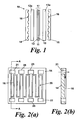
conventional fuel cell 10 is shown infigure 1 which for clarity, illustrates the various layers in exploded form. A solid polymerion transfer membrane 11 is sandwiched between ananode 12 and acathode 13. Typically, theanode 12 and thecathode 13 are both formed from an electrically conductive, porous material such as porous carbon, to which small particles of platinum and/or other precious metal catalyst are bonded. Theanode 12 andcathode 13 are often bonded directly to the respective adjacent surfaces of themembrane 11. This combination is commonly referred to collectively as the membrane-electrode assembly, orMEA 17. - Sandwiching the polymer membrane and porous electrode layers is an anode fluid
flow field plate 14 and a cathode fluidflow field plate 15.Intermediate backing layers flow field plate 14 and theanode 12 and similarly between the cathode fluidflow field plate 15 and thecathode 13. The backing layers are of a porous nature and fabricated so as to ensure effective diffusion of gas to and from the anode and cathode surfaces as well as assisting in the management of water vapour and liquid water. - The fluid
flow field plates respective anode electrode 12 orcathode electrode 13. At the same time, the fluid flow field plates facilitate the delivery and/or exhaust of fluid fuel, oxidant and/or reaction product to or from theporous electrodes channels 16 in the surface presented to theporous electrodes figure 2(a) , one conventional configuration of fluid flow channel provides aserpentine structure 20 in a face of the anode 14 (or cathode 15) fluid flow field plate, having aninlet pont 21 and anoutlet port 22 as shown infigure 2(a) . According to conventional design, it will be understood that theserpentine structure 20 comprises achannel 16 in the surface of the plate 14 (or 15), while theports serpentine structure 20 can be communicated throughout the depth of a stack of plates in a direction orthogonal to the plate as particularly indicated by the arrow in the cross-section on A-A shown in thefigure 2(b) . - With reference to
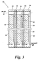
figure 3 , in a conventionalfuel cell assembly 30, stacks of plates are built up. In this arrangement, adjacent anode and cathode fluid flow field plates are combined in conventional manner to form a singlebipolar plate 31 havinganode channels 32 on one face andcathode channels 33 on the opposite face, each adjacent to a respective membrane-electrode assembly (MEA) 34. The inlet port apertures 21 andoutlet port apertures 22 are all overlaid to provide inlet and outlet manifolds to the entire stack. The various elements of the stack are shown slightly separated for clarity, although it will be understood for the purposes of the present invention that they will be compressed together using sealing gaskets. - Referring to
figure 4 , a schematic partial view of a conventional MEA anddiffuser assembly 41 is shown, in whichdiffuser layers 43 are provided on each side of theMEA 44. A series offluid ports 42 are provided within the MEA 44. Thesefluid ports 42 are provided to coincide with fluid ports in corresponding fluid flow plates and gaskets which, when assembled together in a stack, form manifolds for communicating fluid in a direction orthogonal to the planes of the MEAs. These manifolds are used to transport fluids through the depth of the stack to and from thediffuser layers 43. - A section indicated by line A-A' in
figure 4 is shown in a partial schematic cross sectional view infigure 5 . TheMEA 44, withdiffuser layers flow field plates Sealing surfaces 54a-d are provided between theMEA 44 and thefluid flow plates gaskets MEA 44 and outside the region defined by thediffuser layers fluid seals 54a-d, and other fluid seals illustrated further, are not intended to indicate separate components of a fuel cell assembly, but to indicate areas of contact with a gasket where a fluid seal is formed when theMEA 44, thegaskets flow field plates - A relatively
incompressible shim 53 may be provided on a surface of thefluid flow plate 52a, for example to allow flow of fluid to or from thediffuser layer 43a through channels provided in the shim, and/or to prevent thegasket 51a closing up channels provided in the fluidflow field plate 52a when under pressure. A fluid seal may also be provided against the shim, although this is less important to the operation of the fuel cell than theother fluid seals 54a-d, since the volume surrounding theshim 53 is typically otherwise sealed. This optional fluid seal is therefore not indicated in this and in further figures. - In
figure 5 and subsequent figures theshim 53 is shown extending into a region at least partially occupied by thediffuser 43a, which may for example correspond to an anode or cathode side into which cooling water is to be injected via channels formed within theshim 53. Such cooling water may be injected through other ports (not shown) provided within the fluid flow field plates that are also in fluid communication with theshim 53. - The conventional arrangement for a fuel cell assembly as shown in
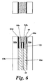
figure 5 has a total of foursealing surfaces 54a-54d for each MEA, formed on twoseparate gaskets - One way of reducing the number of components is to unify the
gaskets figure 6 . In this arrangement,sealing surfaces gasket 61 and the fluidflow field plates sealing surfaces gasket 61 and theMEA 44 are provided within thesame gasket 61, through the cross-section of thegasket 61 being in the form of a c-shape. Themoulded gasket 61 effectively encapsulates the outer perimeter of the MEA 44. To achieve such a result requires tight control of the gasket dimensions so that the thickness of thegasket 61 is consistent with the working dimension of theMEA 44, together with thediffuser layers moulded gaskets 61 increases costs and reduces the design flexibility of the fuel cell. -
US 6316139 discloses a polymer electrolyte fuel cell using a gasket including an elastomer layer provided with an adhesive layer, the elastomer layer being adhered to at least one side of a separator plate via the adhesive layer. -
WO 2006/024735 discloses a static seal comprising a layer of elastomer cold-deposited on a face of a support and subsequently shaped in a heated mould also used for curing, forming threads or ribs on the seal. - It is an object of the present invention to provide an improved gasket design.
- According to aspects of the invention, as defined by the appended claims, there is provided a fuel cell assembly and a method of forming a fuel cell assembly.
- Embodiments of the present invention will now be described by way of example and with reference to the accompanying drawings in which:
-
Figure 1 shows a schematic cross-sectional view through a part of a conventional fuel cell; -
Figures 2(a) and 2(b) respectively show a simplified plan and sectional view of a fluid flow field plate of the fuel cell offigure 1 ; -
Figure 3 shows a cross-sectional view through a conventional fuel cell stack with bipolar plates; -
Figure 4 shows a schematic plan view of a portion of a membrane-electrode assembly; -
Figure 5 shows a schematic cross-sectional view on line A-A' of a portion of the membrane-electrode assembly offigure 4 situated between two fluid flow field plates and sealed with conventional gaskets; -
Figure 6 shows a schematic cross-sectional view of a gasket arrangement for sealing a membrane-electrode assembly; -
Figure 7 shows a schematic cross-sectional view of a further gasket arrangement for sealing a membrane-electrode assembly; -
Figure 8 shows a schematic cross-sectional view of a further gasket arrangement for sealing a membrane-electrode assembly; -
Figure 9 shows a schematic plan view of a membrane-electrode assembly in position over a gasket; -
Figure 10 shows a perspective view of the construction of part of a gasket comprising a plurality of cavities; -
Figure 11 shows a cross-sectional view of a portion of the gasket offigure 10 ; and -
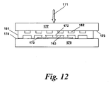
Figure 12 shows a cross-sectional schematic view of a portion of a gasket offigure 10 while under an applied pressure. - The conventional designs of anode and cathode fluid flow plates incorporating fluid flow channels in the faces thereof have already been discussed in connection with
figures 1 to 3 , and the arrangement of a typical gasket for use with such plates in connection withfigure 4 to 6 . - The present invention takes account of the observation that, for a fuel cell unit to be sealed to allow it to function, a fluid seal is only required on one surface of the MEA, as opposed to both surfaces of the MEA as shown in
figures 5 and6 , and this can be achieved with a unitary gasket. An MEA 44 sealed on only onesurface 76 is illustrated schematically infigure 7 , where the MEA 44 is sealed against agasket 72 along a sealingsurface 74b. Provided this surface is adequately sealed, theopposite surface 75 of the MEA does not need to be sealed against thegasket 72, since the sealingsurface 74c prevents undesired passage of fluid from within or without the MEA, and thesealing surface 74b prevents the passage of fluid from one side of the MEA to the other (the membrane of theMEA 44 permitting substantially only protonic conduction). - Thus, the
gasket 72, by being in contact with both fluidflow field plates diffuser layers sealing surface 74b on afirst surface 76 of theMEA 44, with the mating surfaces of this fluid seal being provided between a perimeter of theMEA 44 and thegasket 72. - Thus, it can be seen that the
gasket 72 is provided with afirst sealing surface 74a on a first face of the gasket and asecond sealing surface 74c on an opposing face of thegasket 72. The gasket also has athird sealing surface 74b and defines a step profile between the second sealing surface and the third sealing surface. The first and second sealing surfaces provide fluid seals against first and second fluid flow field plates, respectively. Thethird sealing surface 74b provides a fluid seal against only afirst face 76 of theMEA 44. Thethird sealing surface 74b is substantially plane parallel to the first 74a and second 74c sealing surfaces. Asecond surface 75 of the MEA does not form a fluid seal against thegasket 72. In the example shown infigure 7 , afirst portion 77 of thegasket 72 extending between thesecond sealing surface 74c and thefirst sealing surface 74a is of a thickness t1 which is greater than a thickness t2, of asecond portion 78 of thegasket 72 extending between thethird sealing surface 74b and thefirst sealing surface 74a. This difference in thickness (t1-t2) is preferably designed to accommodate the thickness of theMEA 44 and thediffuser layer 73b so that thefluid seal 74b may be provided without significant distortion of the gasket material. - The
gasket 72 may be formed by, for example, moulding or any other suitable process that can result in the required step profile cross-section with a reduced thickness at thethird sealing surface 74b. - An alternative sealing arrangement following a similar general principle is shown schematically in
figure 8 . In this, agasket 82 is preferably initially of uniform thickness, i.e. when under no applied pressure, but is of a type that is of variable or increased compressibility. Examples of gaskets with increased variable compressibility are disclosed inGB 2434845 gasket 82 to increase the local compressibility of the gasket material in that portion. For example, cavities may be provided in at least the portion of thegasket 82 defined by athird sealing surface 84b. The local increase in compressibility permits thegasket 82 to compress further under the same applied pressure. Thegasket 82 may thereby compress to a required thickness t2 to accommodate theMEA 44 in the region defined by athird sealing surface 84b without a reduced ability to provide fluid seals at afirst sealing surface 84a and asecond sealing surface 84c. This arrangement preferably provides for thethird sealing surface 84b to be at least partially obliquely angled relative to the first 84a and second 84c sealing surfaces to avoid undue distortion of theMEA 44. - The use of a region of reduced thickness, as in
figure 7 , or a region of increased compressibility, e.g. through a plurality of cavities as infigure 8 , or a combination of both, facilitates an adequate fluid seal around theMEA 44 using a single gasket without requiring a 're-entrant' or c-shaped profile as in thegasket 61 offigure 6 . - In both of the embodiments of
figures 7 and8 it can be seen that thethird sealing surface second sealing surface - An advantage of the present invention as described above is that the number of components required for sealing a fuel cell is reduced, through a reduction in the number of sealing surfaces. Further advantages include a reduction in complexity of assembly of such a fuel cell, and a potentially more cost-effective MEA design through a reduction in the total MEA area. The invention also enables a fuel cell to be built up in sequential layers, as detailed below.
-
Figure 9 illustrates schematically an arrangement showing how anMEA 91, with adiffuser layer 93 on both sides thereof, may be positioned in place over agasket 82. The MEA in this example is reduced in size compared to that shown infigure 4 . Anouter perimeter 95 of theMEA 91 overlies thegasket 82, such that aninner perimeter 96 of thegasket 82 lies entirely within the MEAouter perimeter 95. When in place between the two fluidflow field plates third sealing surface 84b is provided on an inside peripheral surface of thegasket 82, extending between the MEAouter perimeter 95 and the gasketinner perimeter 96, thereby providing a fluid seal between the inside peripheral surface of thegasket 82 and an outside peripheral surface of theMEA 91. This arrangement can effectively seal the MEAouter perimeter 95 from the external atmosphere, which will limit dehydration of the membrane of the MEA in use. - In a general aspect, the
gasket 82 has no re-entrant inner face to seal against theMEA 44. Referring tofigures 7 and8 , a fuel cell stack comprising thegasket flow field plate 52a, thegasket diffuser layer MEA 44, thediffuser layer flow field plate 52b. The gasket does not need to be pre-formed onto the MEA and thus does not need to be customised to an exact cell configuration. - A preferred embodiment where the
gasket 82 is provided with a plurality of cavities proximate at least a portion of one or both surfaces is further illustrated infigures 10 to 12 . -
Figure 10 illustrates a representative portion of agasket 153 suitable for the present invention. Thegasket 153 has afirst sealing surface 154 and asecond sealing surface 155. A first plurality ofcavities 156 is provided within thegasket 153 at the first sealing surface and expending over the portion of the gasket. Thecavities 156 extend in a regular array over the portion of thegasket 153 shown. Also shown is a second plurality ofcavities 157 provided within the gasket at thesecond sealing surface 155, being in this example substantially similar in size and arrangement to the first plurality of cavities. - Although the
cavities 156 are shown infigure 10 as being provided at thesurface 154, in other embodiments thecavities 156 may be provided below thesurface 154, but sufficiently close to the surface so as to influence the local surface compressibility through the thickness of thegasket 153. - The sealing surfaces 154, 155 of the gasket are defined as being those surfaces which comes into contact with the surface of a component to which the gasket is to be sealed. The sealing surface does not generally therefore include the interior surface of the
cavities gasket 153 is increased, a proportion of the interior surface of thecavities gasket 153, which proportion increases with increasing applied pressure. - The term "cavity density" is used herein as a measure of the number of cavities present over any defined area of the
gasket 153. The cavity density over afirst sealing surface 154 of a portion of thegasket 153 may be different from the cavity density over asecond sealing surface 155 of the same portion of thegasket 153. For example, if the area of the sealingsurface 154 of thegasket 153 offigure 10 is 1 cm2 and the number of cavities is 36, the cavity density on the first sealing surface is 36 cm-2. - The term "cavity volume" as used herein is the total void volume of any given cavity, which may be usefully given in terms of an average figure for cavities in the
gasket 153 or a certain region thereof. - It will be recognised that the cavity density and the cavity volume in a region of the gasket will each, at least in part, determine the compressibility of that region of the gasket.
- The gasket preferably comprises a compressible material that, in use, has sufficient compressibility to seal against the various internal surfaces of a fuel cell assembly in which the gasket is to be used.
- The term "compressible material" is intended to encompass solid materials which can be significantly deformed under applied compressive pressure, and whose physical mechanical properties may be characterised by a combination of elastic, i.e. recoverable, and plastic, i.e. permanent and non-recoverable, deformation under an applied pressure. Time-dependent effects such as creep and viscoelasticity may also define in part the properties of the compressible material. An increase in the compressibility of a region of the gasket will correspond to a reduction in the pressure needed to compress the total thickness of that region by the same degree. Alternatively put, the same applied pressure will cause the total thickness of that region to be reduced by a greater degree.
- Shown in
figure 11 is a cross-sectional view of an alternative asymmetric arrangement ofcavities gasket 161 suitable for the present invention, in which the cavity volumes are different on thefirst sealing surface 164 andsecond sealing surface 165.Cavities 162 proximate thefirst sealing surface 164 are of different dimensions tocavities 163 proximate thesecond sealing surface 165. The result of this type of variation in cavity volume will be that thegasket material 166 between thelarger cavities 163 is able to compress further than thegasket material 167 between thesmaller cavities 162 under the same applied pressure. - A similar effect to that shown in
figure 11 may be obtained by, instead of altering the average cavity volume beneath each of the first 164 and second 165 sealing surfaces, altering the spacing between the cavities and thus affecting the cavity density. - The cavity density and / or cavity volumes may be different on at least selected opposing surface portions of the gasket proximate the first 164 and second 165 sealing surfaces, the opposing surface portions being selected regions of the first 164 and second 165 sealing surfaces that are substantially coextensive on opposite sealing surfaces of the
gasket 161. - In such an asymmetric arrangement in the
gasket 161 offigure 11 , the surface adhesion properties can consequently be biased towards one surface. The contact area of onesealing surface 164 of thegasket 161 compared to theother sealing surface 165 will tend to prefer adherence to one surface over the other without the need for adhesives or surface preparations. - Shown in
figure 12 is a schematic view in cross-section of the behaviour of such agasket 161 under compression between anupper component 177 and alower component 176. Thegasket 161 is situated between twocomponent surfaces lower component surface 174 is situated asurface feature 173, which protrudes out of the plane of thecomponent surface 174. Applying pressure in the direction indicated byarrow 171 causes the gasket material in the compensatingregion 172 to compress further than the material outside the compensating region. Additional compression of the gasket is taken up within the volume of the gasket itself, and does not cause any additional bulging around the external perimeter of thegasket 161. Thecavities 163 permit the surrounding gasket material within the compensatingregion 172 to bulge into thecavities 163 along directions orthogonal to the direction of application of force. Thesurface feature 173 could, for example, be a foil or shim of relatively incompressible material, such as a water distribution foil, positioned to cover selected regions of the fluid flow plate. Preferably, for the purpose of the present invention, the surface feature is that of theperimeter edge 95 of theMEA 91, as described in relation tofigure 9 . Since thegasket 161 is able to compressibly deform around thesurface feature 173, the seal around thesurface feature 173 is not compromised by its presence. - The
gasket rectangular cavities figure 10 . Other types of regular repeating patterns such as hexagonal or triangular patterns are also envisaged. Non-repeating patterns or random distributions of cavities, which also may be characterised by a cavity density and an average cavity volume, are also envisaged to be within the scope of the invention. - It is to be understood that the term "cavities" is intended to encompass definitions that apply to arrays of individually isolated cavities across a gasket, as well as arrays of interconnected cavities formed within arrays of individually isolated pillars or other raised features. The gasket may comprise either one or both types of cavities across at least a portion of one or more sealing surfaces.
- It is envisaged that a variety of conventional gasket materials may be used in the present invention, such as silicone, nitrile or butyl rubbers. However, other materials, such as expanded PTFE, may also be used.
- The thickness of the gasket is preferably less than 10mm. More preferably, the uncompressed gasket thickness lies between 0.1 and 3mm, and more preferably still between 0.1 and 1mm.
- Preferably, the average volume of the
cavities - The cavities of the
gasket - Cavities as described above may be provided in at least a portion of the gasket. For example, cavities may be provided over the region of the gasket defining the
third sealing surface 84b, so that the additional thickness of theMEA 44 may be accommodated in that region. Alternatively, cavities may be provided over a greater portion of a surface of the gasket, or over portions or the whole of both surfaces. - Other embodiments are envisaged to be within the scope of the invention, as defined by the appended claims.
Claims (7)
- A fuel cell assembly comprising:a first fluid flow field plate (52a);a second fluid flow field plate (52b);a membrane electrode assembly (44) having first and second opposing faces (76, 75), interposed between the first and second fluid flow field plates;a gasket (72, 82) extending between the first and second fluid flow field plates and forming respective first and second sealing surfaces (74a, 74c; 84a, 84c) therewith,the gasket also defining a third sealing surface (74b, 84b), by which the gasket is in contact with only one face of the membrane electrode assembly (44),characterised in that the gasket (72, 82) has a region of increased compressibility on the third sealing surface (74b, 84b) compared to the second sealing surface (74c, 84c).
- The fuel cell assembly of claim 1 in which the third sealing surface (74b, 84b) is inwardly adjacent to the second sealing surface (74c, 84c).
- The fuel cell assembly of claim 1 in which the third sealing surface (74b) is plane parallel to the second sealing surface (74c).
- The fuel cell assembly of claim 1 wherein the third sealing surface (84b) is obliquely angled relative to the second sealing surface (84c).
- The fuel cell assembly of claim 1 in which the gasket (72) defines a step profile between the second and third sealing surfaces (74c, 74b).
- A method of forming a fuel cell assembly, comprising the sequential steps of:(i) providing a first fluid flow field plate (52a)(ii) laying a gasket (72, 82) on the first fluid flow field plate, the gasket having a first sealing surface (74a, 84a), a second sealing surface (74c, 84c) and a third sealing surface (74b, 84b), the third sealing surface being entirely enclosed within a boundary defined by an inner perimeter of the second sealing surface, the gasket (72, 82) having a region of increased compressibility on the third sealing surface compared to the second sealing surface, the first sealing surface being laid against the first fluid flow field plate (52a);(iii) laying a membrane-electrode assembly (44) on the gasket, a perimeter edge portion of a first surface of the membrane-electrode assembly overlying the third sealing surface (74b, 84b) of the gasket;(iv) positioning a second fluid flow field plate (52b) over the membrane electrode assembly and the gasket, the second fluid flow field plate overlaying the second sealing surface and a second surface of the membrane-electrode assembly; and(v) applying compressive pressure between the first and second fluid flow field plates (52a, 52b) across the gasket (72, 82) and membrane electrode assembly (44) to provide fluid seals between (i) the first sealing surface (74a, 84a) of the gasket and the first fluid flow plate (52a), (ii) the second sealing surface (74c, 84c) of the gasket and the second fluid flow plate (52b), and (iii) the third sealing surface (74b, 84b) of the gasket and membrane-electrode assembly (44), the gasket sealing against only one face of the membrane-electrode assembly.
- The method of claim 6 further including the steps of:laying a first diffuser layer (73a) onto the first fluid flow plate (52a) within the inner periphery of the gasket, after step (i) or step (ii); andlaying a second diffuser layer (73b) onto the membrane-electrode assembly (44) after step (iii).
Applications Claiming Priority (2)
| Application Number | Priority Date | Filing Date | Title |
|---|---|---|---|
| GB0609566A GB2437994A (en) | 2006-05-13 | 2006-05-13 | Gaskets for fuel cells |
| PCT/GB2007/001759 WO2007132219A2 (en) | 2006-05-13 | 2007-05-14 | Gaskets for fuel cells |
Publications (2)
| Publication Number | Publication Date |
|---|---|
| EP2022118A2 EP2022118A2 (en) | 2009-02-11 |
| EP2022118B1 true EP2022118B1 (en) | 2012-01-18 |
Family
ID=36637483
Family Applications (1)
| Application Number | Title | Priority Date | Filing Date |
|---|---|---|---|
| EP07732784A Not-in-force EP2022118B1 (en) | 2006-05-13 | 2007-05-14 | Gaskets for fuel cells |
Country Status (16)
| Country | Link |
|---|---|
| US (1) | US8338057B2 (en) |
| EP (1) | EP2022118B1 (en) |
| JP (1) | JP5350225B2 (en) |
| KR (1) | KR101382514B1 (en) |
| CN (1) | CN101443939B (en) |
| AR (1) | AR060917A1 (en) |
| AT (1) | ATE542254T1 (en) |
| BR (1) | BRPI0711466A2 (en) |
| CA (1) | CA2651625C (en) |
| ES (1) | ES2395111T3 (en) |
| GB (1) | GB2437994A (en) |
| MX (1) | MX2008014576A (en) |
| RU (1) | RU2414773C2 (en) |
| TW (1) | TWI426651B (en) |
| WO (1) | WO2007132219A2 (en) |
| ZA (1) | ZA200809624B (en) |
Families Citing this family (7)
| Publication number | Priority date | Publication date | Assignee | Title |
|---|---|---|---|---|
| JP4957091B2 (en) * | 2006-06-26 | 2012-06-20 | トヨタ自動車株式会社 | Fuel cell |
| JP5194439B2 (en) * | 2006-11-21 | 2013-05-08 | トヨタ自動車株式会社 | Fuel cell and assembly constituting the fuel cell |
| JP2010040414A (en) * | 2008-08-07 | 2010-02-18 | Panasonic Corp | Fuel cell stack and fuel cell using it |
| GB2472450A (en) * | 2009-08-07 | 2011-02-09 | Afc Energy Plc | Cell Stack Plates |
| RU2599750C2 (en) * | 2015-02-10 | 2016-10-10 | Открытое акционерное общество "Волжский завод асбестовых технических изделий" | Layered sealing material |
| JP6859823B2 (en) * | 2017-04-17 | 2021-04-14 | トヨタ自動車株式会社 | Fuel cell |
| GB2566334B (en) | 2017-09-12 | 2022-11-23 | Ceres Ip Co Ltd | A stack of intermediate temperature, metal-supported, solid oxide fuel cell units |
Family Cites Families (20)
| Publication number | Priority date | Publication date | Assignee | Title |
|---|---|---|---|---|
| AU664703B2 (en) * | 1991-06-04 | 1995-11-30 | Ballard Power Systems Inc. | Gasketed membrane electrode assembly for electrochemical fuel cells |
| JPH0696783A (en) | 1992-09-16 | 1994-04-08 | Matsushita Electric Ind Co Ltd | Fuel cell |
| JPH07312223A (en) * | 1994-05-17 | 1995-11-28 | Matsushita Electric Ind Co Ltd | Fuel cell |
| RU2174728C2 (en) * | 1994-10-12 | 2001-10-10 | Х Пауэр Корпорейшн | Fuel cell using integrated plate technology for liquid-distribution |
| JP3353567B2 (en) * | 1995-09-29 | 2002-12-03 | 松下電器産業株式会社 | Fuel cell |
| JPH11219714A (en) * | 1998-02-03 | 1999-08-10 | Matsushita Electric Ind Co Ltd | Fuel cell |
| JP3820883B2 (en) * | 1999-04-27 | 2006-09-13 | Nok株式会社 | Gasket for fuel cell |
| JP3400415B2 (en) * | 2000-07-25 | 2003-04-28 | 本田技研工業株式会社 | Fuel cell seal structure |
| US7226686B2 (en) * | 2001-04-23 | 2007-06-05 | Nok Corporation | Fuel cell and method of manufacturing the fuel cell |
| JP4316164B2 (en) * | 2001-07-10 | 2009-08-19 | 本田技研工業株式会社 | Membrane / electrode structure and fuel cell |
| US6733915B2 (en) * | 2001-12-27 | 2004-05-11 | E. I. Du Pont De Nemours And Company | Gas diffusion backing for fuel cells |
| JP3616065B2 (en) * | 2002-03-22 | 2005-02-02 | 大同メタル工業株式会社 | Air-breathing fuel cell |
| US7087339B2 (en) * | 2002-05-10 | 2006-08-08 | 3M Innovative Properties Company | Fuel cell membrane electrode assembly with sealing surfaces |
| US7217471B2 (en) * | 2002-05-17 | 2007-05-15 | 3M Innovative Properties Company | Membrane electrode assembly with compression control gasket |
| US7405019B2 (en) * | 2003-03-14 | 2008-07-29 | Matsushita Electric Industrial Co., Ltd. | Polymer electrolyte fuel cell |
| US7595126B2 (en) * | 2003-11-26 | 2009-09-29 | Delphi Technologies, Inc. | PEM fuel cell assembly formed of modular sub-assemblies |
| GB2413002B (en) * | 2004-04-08 | 2006-12-06 | Intelligent Energy Ltd | Fuel cell gas distribution |
| JP2006004799A (en) * | 2004-06-18 | 2006-01-05 | Nok Corp | Gasket for fuel cell |
| FR2873777B1 (en) * | 2004-08-02 | 2008-10-03 | Fed Mogul Sealing Systems Soc | STATIC SEALING JOINT |
| GB2434845B (en) | 2006-02-01 | 2010-10-13 | Intelligent Energy Ltd | Variable compressibility gaskets |
-
2006
- 2006-05-13 GB GB0609566A patent/GB2437994A/en not_active Withdrawn
-
2007
- 2007-05-11 TW TW096116788A patent/TWI426651B/en not_active IP Right Cessation
- 2007-05-14 WO PCT/GB2007/001759 patent/WO2007132219A2/en not_active Ceased
- 2007-05-14 RU RU2008149139/07A patent/RU2414773C2/en not_active IP Right Cessation
- 2007-05-14 US US12/300,616 patent/US8338057B2/en not_active Expired - Fee Related
- 2007-05-14 BR BRPI0711466-4A patent/BRPI0711466A2/en not_active IP Right Cessation
- 2007-05-14 MX MX2008014576A patent/MX2008014576A/en active IP Right Grant
- 2007-05-14 EP EP07732784A patent/EP2022118B1/en not_active Not-in-force
- 2007-05-14 AR ARP070102070A patent/AR060917A1/en active IP Right Grant
- 2007-05-14 CN CN2007800173507A patent/CN101443939B/en not_active Expired - Fee Related
- 2007-05-14 JP JP2009510532A patent/JP5350225B2/en not_active Expired - Fee Related
- 2007-05-14 CA CA2651625A patent/CA2651625C/en not_active Expired - Fee Related
- 2007-05-14 AT AT07732784T patent/ATE542254T1/en active
- 2007-05-14 ES ES07732784T patent/ES2395111T3/en active Active
- 2007-05-14 KR KR1020087030362A patent/KR101382514B1/en not_active Expired - Fee Related
-
2008
- 2008-11-11 ZA ZA2008/09624A patent/ZA200809624B/en unknown
Also Published As
| Publication number | Publication date |
|---|---|
| EP2022118A2 (en) | 2009-02-11 |
| ES2395111T3 (en) | 2013-02-08 |
| TWI426651B (en) | 2014-02-11 |
| WO2007132219A2 (en) | 2007-11-22 |
| TW200810220A (en) | 2008-02-16 |
| JP2009537940A (en) | 2009-10-29 |
| AR060917A1 (en) | 2008-07-23 |
| KR20090025235A (en) | 2009-03-10 |
| CA2651625A1 (en) | 2007-11-22 |
| MX2008014576A (en) | 2008-11-27 |
| CA2651625C (en) | 2014-09-30 |
| ATE542254T1 (en) | 2012-02-15 |
| GB0609566D0 (en) | 2006-06-21 |
| CN101443939A (en) | 2009-05-27 |
| BRPI0711466A2 (en) | 2011-11-16 |
| CN101443939B (en) | 2011-10-19 |
| US20090311569A1 (en) | 2009-12-17 |
| RU2414773C2 (en) | 2011-03-20 |
| GB2437994A (en) | 2007-11-14 |
| KR101382514B1 (en) | 2014-04-07 |
| ZA200809624B (en) | 2012-04-24 |
| WO2007132219A3 (en) | 2008-01-17 |
| US8338057B2 (en) | 2012-12-25 |
| RU2008149139A (en) | 2010-06-20 |
| JP5350225B2 (en) | 2013-11-27 |
Similar Documents
| Publication | Publication Date | Title |
|---|---|---|
| EP1984661B1 (en) | Variable compressibility gaskets | |
| EP2033250B1 (en) | Fuel cell and method of manufacturing same | |
| US20010019790A1 (en) | Fuel Cell Gasket Assembly and Method of Assembling Fuel Cells | |
| CA2651625C (en) | Gaskets for fuel cells | |
| US9673458B2 (en) | Fuel cell | |
| EP2759011B1 (en) | Fuel cell assembly | |
| KR20240089587A (en) | Frames for PEM electrolytic cells and PEM electrolytic cell stacks for high-pressure hydrogen production by differential pressure electrolysis | |
| EP3257097B1 (en) | Seal for solid polymer electrolyte fuel cell | |
| US20080166617A1 (en) | Fuel cell and cell assembly for fuel cell | |
| US10003098B2 (en) | Fuel cell | |
| WO2004061338A1 (en) | Fuel cell seal with integral bridge | |
| WO2010082934A1 (en) | Fuel cell seal | |
| MX2008010014A (en) | Variable compressibility gaskets | |
| CN116895780A (en) | Enhanced sealed fuel cell assembly |
Legal Events
| Date | Code | Title | Description |
|---|---|---|---|
| PUAI | Public reference made under article 153(3) epc to a published international application that has entered the european phase |
Free format text: ORIGINAL CODE: 0009012 |
|
| 17P | Request for examination filed |
Effective date: 20081121 |
|
| AK | Designated contracting states |
Kind code of ref document: A2 Designated state(s): AT BE BG CH CY CZ DE DK EE ES FI FR GB GR HU IE IS IT LI LT LU LV MC MT NL PL PT RO SE SI SK TR |
|
| AX | Request for extension of the european patent |
Extension state: AL BA HR MK RS |
|
| DAX | Request for extension of the european patent (deleted) | ||
| 17Q | First examination report despatched |
Effective date: 20100309 |
|
| RAP1 | Party data changed (applicant data changed or rights of an application transferred) |
Owner name: INTELLIGENT ENERGY LIMITED |
|
| GRAP | Despatch of communication of intention to grant a patent |
Free format text: ORIGINAL CODE: EPIDOSNIGR1 |
|
| RAP1 | Party data changed (applicant data changed or rights of an application transferred) |
Owner name: INTELLIGENT ENERGY LIMITED |
|
| GRAS | Grant fee paid |
Free format text: ORIGINAL CODE: EPIDOSNIGR3 |
|
| GRAA | (expected) grant |
Free format text: ORIGINAL CODE: 0009210 |
|
| AK | Designated contracting states |
Kind code of ref document: B1 Designated state(s): AT BE BG CH CY CZ DE DK EE ES FI FR GB GR HU IE IS IT LI LT LU LV MC MT NL PL PT RO SE SI SK TR |
|
| REG | Reference to a national code |
Ref country code: GB Ref legal event code: FG4D |
|
| REG | Reference to a national code |
Ref country code: CH Ref legal event code: EP |
|
| REG | Reference to a national code |
Ref country code: AT Ref legal event code: REF Ref document number: 542254 Country of ref document: AT Kind code of ref document: T Effective date: 20120215 Ref country code: IE Ref legal event code: FG4D |
|
| REG | Reference to a national code |
Ref country code: NL Ref legal event code: T3 |
|
| REG | Reference to a national code |
Ref country code: DE Ref legal event code: R096 Ref document number: 602007020162 Country of ref document: DE Effective date: 20120315 |
|
| RAP2 | Party data changed (patent owner data changed or rights of a patent transferred) |
Owner name: INTELLIGENT ENERGY LIMITED |
|
| LTIE | Lt: invalidation of european patent or patent extension |
Effective date: 20120118 |
|
| PG25 | Lapsed in a contracting state [announced via postgrant information from national office to epo] |
Ref country code: BG Free format text: LAPSE BECAUSE OF FAILURE TO SUBMIT A TRANSLATION OF THE DESCRIPTION OR TO PAY THE FEE WITHIN THE PRESCRIBED TIME-LIMIT Effective date: 20120418 Ref country code: LT Free format text: LAPSE BECAUSE OF FAILURE TO SUBMIT A TRANSLATION OF THE DESCRIPTION OR TO PAY THE FEE WITHIN THE PRESCRIBED TIME-LIMIT Effective date: 20120118 Ref country code: BE Free format text: LAPSE BECAUSE OF FAILURE TO SUBMIT A TRANSLATION OF THE DESCRIPTION OR TO PAY THE FEE WITHIN THE PRESCRIBED TIME-LIMIT Effective date: 20120118 Ref country code: IS Free format text: LAPSE BECAUSE OF FAILURE TO SUBMIT A TRANSLATION OF THE DESCRIPTION OR TO PAY THE FEE WITHIN THE PRESCRIBED TIME-LIMIT Effective date: 20120518 |
|
| PG25 | Lapsed in a contracting state [announced via postgrant information from national office to epo] |
Ref country code: LV Free format text: LAPSE BECAUSE OF FAILURE TO SUBMIT A TRANSLATION OF THE DESCRIPTION OR TO PAY THE FEE WITHIN THE PRESCRIBED TIME-LIMIT Effective date: 20120118 Ref country code: PL Free format text: LAPSE BECAUSE OF FAILURE TO SUBMIT A TRANSLATION OF THE DESCRIPTION OR TO PAY THE FEE WITHIN THE PRESCRIBED TIME-LIMIT Effective date: 20120118 Ref country code: PT Free format text: LAPSE BECAUSE OF FAILURE TO SUBMIT A TRANSLATION OF THE DESCRIPTION OR TO PAY THE FEE WITHIN THE PRESCRIBED TIME-LIMIT Effective date: 20120518 Ref country code: FI Free format text: LAPSE BECAUSE OF FAILURE TO SUBMIT A TRANSLATION OF THE DESCRIPTION OR TO PAY THE FEE WITHIN THE PRESCRIBED TIME-LIMIT Effective date: 20120118 Ref country code: GR Free format text: LAPSE BECAUSE OF FAILURE TO SUBMIT A TRANSLATION OF THE DESCRIPTION OR TO PAY THE FEE WITHIN THE PRESCRIBED TIME-LIMIT Effective date: 20120419 |
|
| REG | Reference to a national code |
Ref country code: AT Ref legal event code: MK05 Ref document number: 542254 Country of ref document: AT Kind code of ref document: T Effective date: 20120118 |
|
| PG25 | Lapsed in a contracting state [announced via postgrant information from national office to epo] |
Ref country code: CY Free format text: LAPSE BECAUSE OF FAILURE TO SUBMIT A TRANSLATION OF THE DESCRIPTION OR TO PAY THE FEE WITHIN THE PRESCRIBED TIME-LIMIT Effective date: 20120118 |
|
| PG25 | Lapsed in a contracting state [announced via postgrant information from national office to epo] |
Ref country code: CZ Free format text: LAPSE BECAUSE OF FAILURE TO SUBMIT A TRANSLATION OF THE DESCRIPTION OR TO PAY THE FEE WITHIN THE PRESCRIBED TIME-LIMIT Effective date: 20120118 Ref country code: EE Free format text: LAPSE BECAUSE OF FAILURE TO SUBMIT A TRANSLATION OF THE DESCRIPTION OR TO PAY THE FEE WITHIN THE PRESCRIBED TIME-LIMIT Effective date: 20120118 Ref country code: DK Free format text: LAPSE BECAUSE OF FAILURE TO SUBMIT A TRANSLATION OF THE DESCRIPTION OR TO PAY THE FEE WITHIN THE PRESCRIBED TIME-LIMIT Effective date: 20120118 Ref country code: RO Free format text: LAPSE BECAUSE OF FAILURE TO SUBMIT A TRANSLATION OF THE DESCRIPTION OR TO PAY THE FEE WITHIN THE PRESCRIBED TIME-LIMIT Effective date: 20120118 Ref country code: SI Free format text: LAPSE BECAUSE OF FAILURE TO SUBMIT A TRANSLATION OF THE DESCRIPTION OR TO PAY THE FEE WITHIN THE PRESCRIBED TIME-LIMIT Effective date: 20120118 Ref country code: SE Free format text: LAPSE BECAUSE OF FAILURE TO SUBMIT A TRANSLATION OF THE DESCRIPTION OR TO PAY THE FEE WITHIN THE PRESCRIBED TIME-LIMIT Effective date: 20120118 |
|
| PLBE | No opposition filed within time limit |
Free format text: ORIGINAL CODE: 0009261 |
|
| STAA | Information on the status of an ep patent application or granted ep patent |
Free format text: STATUS: NO OPPOSITION FILED WITHIN TIME LIMIT |
|
| PG25 | Lapsed in a contracting state [announced via postgrant information from national office to epo] |
Ref country code: SK Free format text: LAPSE BECAUSE OF FAILURE TO SUBMIT A TRANSLATION OF THE DESCRIPTION OR TO PAY THE FEE WITHIN THE PRESCRIBED TIME-LIMIT Effective date: 20120118 |
|
| 26N | No opposition filed |
Effective date: 20121019 |
|
| PG25 | Lapsed in a contracting state [announced via postgrant information from national office to epo] |
Ref country code: MC Free format text: LAPSE BECAUSE OF NON-PAYMENT OF DUE FEES Effective date: 20120531 |
|
| REG | Reference to a national code |
Ref country code: CH Ref legal event code: PL |
|
| PG25 | Lapsed in a contracting state [announced via postgrant information from national office to epo] |
Ref country code: LI Free format text: LAPSE BECAUSE OF NON-PAYMENT OF DUE FEES Effective date: 20120531 Ref country code: CH Free format text: LAPSE BECAUSE OF NON-PAYMENT OF DUE FEES Effective date: 20120531 Ref country code: AT Free format text: LAPSE BECAUSE OF FAILURE TO SUBMIT A TRANSLATION OF THE DESCRIPTION OR TO PAY THE FEE WITHIN THE PRESCRIBED TIME-LIMIT Effective date: 20120118 |
|
| REG | Reference to a national code |
Ref country code: ES Ref legal event code: FG2A Ref document number: 2395111 Country of ref document: ES Kind code of ref document: T3 Effective date: 20130208 |
|
| REG | Reference to a national code |
Ref country code: DE Ref legal event code: R097 Ref document number: 602007020162 Country of ref document: DE Effective date: 20121019 |
|
| PG25 | Lapsed in a contracting state [announced via postgrant information from national office to epo] |
Ref country code: MT Free format text: LAPSE BECAUSE OF FAILURE TO SUBMIT A TRANSLATION OF THE DESCRIPTION OR TO PAY THE FEE WITHIN THE PRESCRIBED TIME-LIMIT Effective date: 20120118 |
|
| PG25 | Lapsed in a contracting state [announced via postgrant information from national office to epo] |
Ref country code: TR Free format text: LAPSE BECAUSE OF FAILURE TO SUBMIT A TRANSLATION OF THE DESCRIPTION OR TO PAY THE FEE WITHIN THE PRESCRIBED TIME-LIMIT Effective date: 20120118 |
|
| PG25 | Lapsed in a contracting state [announced via postgrant information from national office to epo] |
Ref country code: LU Free format text: LAPSE BECAUSE OF NON-PAYMENT OF DUE FEES Effective date: 20120514 |
|
| PG25 | Lapsed in a contracting state [announced via postgrant information from national office to epo] |
Ref country code: HU Free format text: LAPSE BECAUSE OF FAILURE TO SUBMIT A TRANSLATION OF THE DESCRIPTION OR TO PAY THE FEE WITHIN THE PRESCRIBED TIME-LIMIT Effective date: 20070514 |
|
| PGFP | Annual fee paid to national office [announced via postgrant information from national office to epo] |
Ref country code: ES Payment date: 20150525 Year of fee payment: 9 |
|
| PGFP | Annual fee paid to national office [announced via postgrant information from national office to epo] |
Ref country code: IE Payment date: 20150512 Year of fee payment: 9 Ref country code: IT Payment date: 20150512 Year of fee payment: 9 Ref country code: NL Payment date: 20150513 Year of fee payment: 9 |
|
| REG | Reference to a national code |
Ref country code: FR Ref legal event code: PLFP Year of fee payment: 10 |
|
| REG | Reference to a national code |
Ref country code: NL Ref legal event code: MM Effective date: 20160601 |
|
| REG | Reference to a national code |
Ref country code: IE Ref legal event code: MM4A |
|
| PG25 | Lapsed in a contracting state [announced via postgrant information from national office to epo] |
Ref country code: IT Free format text: LAPSE BECAUSE OF NON-PAYMENT OF DUE FEES Effective date: 20160514 Ref country code: NL Free format text: LAPSE BECAUSE OF NON-PAYMENT OF DUE FEES Effective date: 20160601 |
|
| REG | Reference to a national code |
Ref country code: FR Ref legal event code: PLFP Year of fee payment: 11 |
|
| PG25 | Lapsed in a contracting state [announced via postgrant information from national office to epo] |
Ref country code: IE Free format text: LAPSE BECAUSE OF NON-PAYMENT OF DUE FEES Effective date: 20160514 |
|
| REG | Reference to a national code |
Ref country code: FR Ref legal event code: PLFP Year of fee payment: 12 |
|
| PG25 | Lapsed in a contracting state [announced via postgrant information from national office to epo] |
Ref country code: ES Free format text: LAPSE BECAUSE OF NON-PAYMENT OF DUE FEES Effective date: 20160515 |
|
| REG | Reference to a national code |
Ref country code: ES Ref legal event code: FD2A Effective date: 20181204 |
|
| PGFP | Annual fee paid to national office [announced via postgrant information from national office to epo] |
Ref country code: FR Payment date: 20190527 Year of fee payment: 13 |
|
| PG25 | Lapsed in a contracting state [announced via postgrant information from national office to epo] |
Ref country code: FR Free format text: LAPSE BECAUSE OF NON-PAYMENT OF DUE FEES Effective date: 20200531 |
|
| PGFP | Annual fee paid to national office [announced via postgrant information from national office to epo] |
Ref country code: DE Payment date: 20210527 Year of fee payment: 15 |
|
| PGFP | Annual fee paid to national office [announced via postgrant information from national office to epo] |
Ref country code: GB Payment date: 20210527 Year of fee payment: 15 |
|
| REG | Reference to a national code |
Ref country code: DE Ref legal event code: R119 Ref document number: 602007020162 Country of ref document: DE |
|
| GBPC | Gb: european patent ceased through non-payment of renewal fee |
Effective date: 20220514 |
|
| PG25 | Lapsed in a contracting state [announced via postgrant information from national office to epo] |
Ref country code: GB Free format text: LAPSE BECAUSE OF NON-PAYMENT OF DUE FEES Effective date: 20220514 Ref country code: DE Free format text: LAPSE BECAUSE OF NON-PAYMENT OF DUE FEES Effective date: 20221201 |