EP2021601B1 - Procédé de démarrage de turbines à gas et dispositif de réglage - Google Patents
Procédé de démarrage de turbines à gas et dispositif de réglage Download PDFInfo
- Publication number
- EP2021601B1 EP2021601B1 EP07726521.3A EP07726521A EP2021601B1 EP 2021601 B1 EP2021601 B1 EP 2021601B1 EP 07726521 A EP07726521 A EP 07726521A EP 2021601 B1 EP2021601 B1 EP 2021601B1
- Authority
- EP
- European Patent Office
- Prior art keywords
- fuel
- start sequence
- range
- purging
- gas turbine
- Prior art date
- Legal status (The legal status is an assumption and is not a legal conclusion. Google has not performed a legal analysis and makes no representation as to the accuracy of the status listed.)
- Active
Links
- 238000000034 method Methods 0.000 title claims description 20
- 239000000446 fuel Substances 0.000 claims description 65
- 238000010926 purge Methods 0.000 claims description 37
- 239000000203 mixture Substances 0.000 claims description 11
- 238000012544 monitoring process Methods 0.000 claims 1
- 206010037544 Purging Diseases 0.000 description 24
- 238000002485 combustion reaction Methods 0.000 description 8
- 238000010586 diagram Methods 0.000 description 4
- 230000001133 acceleration Effects 0.000 description 1
- 238000009825 accumulation Methods 0.000 description 1
- 238000000889 atomisation Methods 0.000 description 1
- 238000011161 development Methods 0.000 description 1
- 230000018109 developmental process Effects 0.000 description 1
- 238000002347 injection Methods 0.000 description 1
- 239000007924 injection Substances 0.000 description 1
- 239000007788 liquid Substances 0.000 description 1
- 239000007858 starting material Substances 0.000 description 1
Images

Classifications
-
- F—MECHANICAL ENGINEERING; LIGHTING; HEATING; WEAPONS; BLASTING
- F02—COMBUSTION ENGINES; HOT-GAS OR COMBUSTION-PRODUCT ENGINE PLANTS
- F02C—GAS-TURBINE PLANTS; AIR INTAKES FOR JET-PROPULSION PLANTS; CONTROLLING FUEL SUPPLY IN AIR-BREATHING JET-PROPULSION PLANTS
- F02C7/00—Features, components parts, details or accessories, not provided for in, or of interest apart form groups F02C1/00 - F02C6/00; Air intakes for jet-propulsion plants
- F02C7/26—Starting; Ignition
-
- F—MECHANICAL ENGINEERING; LIGHTING; HEATING; WEAPONS; BLASTING
- F01—MACHINES OR ENGINES IN GENERAL; ENGINE PLANTS IN GENERAL; STEAM ENGINES
- F01D—NON-POSITIVE DISPLACEMENT MACHINES OR ENGINES, e.g. STEAM TURBINES
- F01D19/00—Starting of machines or engines; Regulating, controlling, or safety means in connection therewith
-
- F—MECHANICAL ENGINEERING; LIGHTING; HEATING; WEAPONS; BLASTING
- F02—COMBUSTION ENGINES; HOT-GAS OR COMBUSTION-PRODUCT ENGINE PLANTS
- F02C—GAS-TURBINE PLANTS; AIR INTAKES FOR JET-PROPULSION PLANTS; CONTROLLING FUEL SUPPLY IN AIR-BREATHING JET-PROPULSION PLANTS
- F02C9/00—Controlling gas-turbine plants; Controlling fuel supply in air- breathing jet-propulsion plants
- F02C9/26—Control of fuel supply
-
- F—MECHANICAL ENGINEERING; LIGHTING; HEATING; WEAPONS; BLASTING
- F05—INDEXING SCHEMES RELATING TO ENGINES OR PUMPS IN VARIOUS SUBCLASSES OF CLASSES F01-F04
- F05D—INDEXING SCHEME FOR ASPECTS RELATING TO NON-POSITIVE-DISPLACEMENT MACHINES OR ENGINES, GAS-TURBINES OR JET-PROPULSION PLANTS
- F05D2260/00—Function
- F05D2260/85—Starting
Definitions
- the present invention relates to a starting method for a gas turbine engine and a control device for controlling the start of a gas turbine engine.
- the invention addresses the start reliability of gas turbine engines particularly with regards to achieving light up or ignition (i.e. achieving flame on).
- Optimum ignition conditions for gas turbine engines are subject to variation between starts due to a variety of factors, e.g. ambient temperature, gas turbine temperatures, fuel calorific value, fuel content, pressures, repeatability of fuel and air delivery systems, etc.
- a typical start system for a gas turbine engine one uses an auxiliary drive unit for driving the turbine and a control unit providing a start sequence in which turbine speed and fuel delivery are coordinated to provide a fuel/air mixture at an ignition device allowing a successful ignition.
- the speed of the gas turbine which is during start driven by an auxiliary motor, and/or the fuel flow to the combustion system are progressively increased over a set period of time, the so called light-up window.
- the length of the light-up window is a function of the range of engine speeds at which starting is most likely to occur, typically between 5% and 20% of the rated engine speed and the accumulation rate of fuel in the combustor.
- a number of ignition opportunities appears, the actual number of which depends on the number of sparks that can be delivered per second by the igniter of the gas turbine engine and the length (duration) of the light-up window. Therefore one likes to have the light-up window as long as possible.
- the length of the light-up window is delimited by a number of factors. If, e.g. the turbine is accelerated too quickly the fuel injection system will not have enough time to provide a sufficient amount of fuel before the window of engine speeds at which starting is most likely to occur is exceeded. On the other hand, if the turbine is accelerated too slowly, it may happen that an amount of fuel inside the combustor is reached which could be dangerous to the engine while the turbine speed has still not reached the maximum speed within the light-up window. However, for example the acceleration rate of the turbine depends on the ambient conditions. On a cold day, a battery driven starter motor may not be capable of accelerating the engine quickly due to possible low power supply.
- the same motor with the same battery may be capable of accelerating the engine very quickly.
- a compromise is typically required between maximizing the light-up window to cover for wide variations in the actual optimum window and minimizing the variation rate to increase the number of ignition opportunities (sparks) during the actual optimum window, without establishing a potentially dangerous fuel amount inside the combustion system during the light-up window.
- Typical start sequences for gas turbine engines are, e.g. described in US 5,844,383 , US 5,907,949 , where a temporary increase in fuel flow during start to enhance the heat release is described, US 4,464,895 , where a pulsating (modulated) liquid fuel flow which improves the atomization and thereby the ignition capability is described and in RU 2078971 , where the fuel flow is varied in relation to the operating condition for the gas turbine before start.
- a start sequence is used in which turbine speed and fuel delivery are coordinated so as to provide a fuel/air mixture at an ignition device allowing a successful ignition. If a successful ignition has not occurred by the end of the start sequence, the gas turbine engine is purged and, after the purging, the start sequence is repeated.
- start sequences can be repeated rather quickly.
- the inventive method therefore allows for repeating a number of start sequences before shut down of the engine due to a failure of ignition.
- the turbine speed may be varied, e.g. by use of an external motor, through a range of turbine speeds at which starting is most likely to occur.
- the range of turbine speeds is shifted and/or scaled when repeating the start sequence. In other words, if the turbine speed is, e.g. linearly increased from a starting point to an end point in the start-up window, the starting point and the end point may be shifted from one start sequence to another. Alternatively or simultaneously the range of turbine speeds between the starting point and the end point could be increased, e.g. by lowering the starting point and increasing the end point.
- the shifting and/or scaling of the range of turbine speed may follow a fixed scheme.
- the fuel/air ratio of the fuel/air mixture which is introduced into the combustor may be varied through a range of fuel/air ratios at which starting is most likely to occur in the start sequence.
- the range of fuel/air ratios can be shifted and/or scaled from one start sequence to another.
- the varying of the fuel/air ratio can e.g. be achieved by varying the fuel delivery with respect to the delivery of air, which in turn depends on the rotational speed of the engine.
- the starting and end points of the optimum window for the fuel/air ratio can be shifted and/or scaled, e.g. spread.
- the shifting and/or scaling of the range of fuel/air ratios may follow a fixed scheme.
- the purging and repeating of start sequences is stopped when a predetermined stop condition is reached or a successful ignition is detected.
- a stop condition a preset number of start sequences can be used which shall not be exceeded.
- the inventive control device for controlling a start of a gas turbine engine is suitable for performing the inventive method. It comprises:
- the end of the time period may indicate the end of the purging. If a time period for the purging is not fixed, the purging may be finished when it is detected that the fuel content in the combustor has fallen under a certain level or condition.
- the window generator may comprise a shifting unit and/or a scaling unit which is connected to the processor unit to receive the purging signal.
- the shifting unit and/or the scaling unit is/are adapted to shift and to scale, respectively, the range of turbine speeds and/or the range of fuel/air ratios if it receives the purging signal.
- control device advantageously comprises a counter which is connected to the processor unit for receiving a purging signal.
- the counter is adapted to count the number of purges, and to output a stop signal when a preset number of purges has been counted.
- the stop signal causes the processor unit not to begin another start sequence.
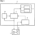
- the control device 3 for controlling the start of a gas turbine engine 1 is shown in form of a block diagram in Figure 1 .
- the control device 3 comprises, in the shown embodiment, a processor unit 5, a window generator 7, an ignition monitor 9, and a counter 19.
- the window generator 7 includes a shifting unit 11 and a scaling unit 13. All units of the control device 3 may be realised as hardware or software.
- the processor unit 5 is connected to the gas turbine engine 1 to begin and control a start sequence in order to light up the engine 1.
- the turbine speed and the fuel to air ratio are ramped up within a light-up window of turbine speeds and fuel to air ratios, respectively.
- the windows are defined by starting and end points for the ramps.
- the fuel to air ratio may be varied by a fuel flow command defining a certain fuel flow for a given turbine speed since the turbine speed also determines the air flow through the combustion system.
- the processor unit 5 receives the actual window for the start sequence from the window generator 7.
- the processor unit 5 is further connected to the ignition monitor 9 which outputs a condition signal representing successful or unsuccessful light-up. To detect successful or unsuccessful light-up the ignition monitor 9 is connected to an ignition detector 21 in the gas turbine engine 1.
- the processor unit 5 is adapted to generate a purging signal if it receives a condition signal from the ignition monitor 9 which represents a failure of ignition.
- the purging signal is then output to the gas turbine engine 1 and causes the engine to stop fuel delivery but to continue with delivery of air. Hence, excess fuel accumulated in the burner and the combustion chamber of the engine is blown out of the engine so that after the purging no potentially dangerous fuel-to-air ratio is present in the combustion system.
- the processor unit 5 outputs another start sequence to the gas turbine engine 1 to make another attempt to light-up the engine.
- the processor unit 5 receives a new light-up window from the window generator 7 after the shifting unit 11 has shifted the range of turbine speeds and/or fuel to air ratios given in a start up window. Additionally or alternatively, the scaling unit 13 has multiplied the range of turbine speeds and/or fuel to air ratios given in a start-up window by a scaling factor. Although, in the present embodiment, a shifting unit 11 and a scaling unit 13 are present, the window generator could, in principle, be equipped with a shifting unit 11 or a scaling unit 13, only.
- the new start-up window which is shifted and/or scaled with respect to preceding start-up window, is output to the processor unit 5. The processor unit 5 then starts the new starting sequence after it has received a new start-up window.
- FIG. 3 A sequence of start-up windows for a number of start-sequences and purgings of the gas turbine engine 1 is schematically shown in Figure 3 .
- the Figure shows a fuel flow demand as a function of time.
- the fuel flow is ramped up which is indicated by the diagonal line in each start-up window 201 to 209.
- the fuel flow demand can be adapted to the rotation speed of the gas turbine engine either so as to provide a fixed fuel/air ratio during a start-up window or so as to provide an increasing fuel/air ratio.
- each light-up window which typically lasts for 2 to 10 seconds, a number of sparks is provided by an ignition system in order to achieve light-up.
- Each purging signal output by the processor unit 5 to the gas turbine engine 1 is also received by a software or hardware counter 19.
- the counter counts up, and when a maximum count number is reached a stop signal is output from the counter 19 to the processor unit 5.
- the stop signal causes the processor unit 5 not to continue with the output of purging signals and to output a shut down signal to the gas turbine engine 1.
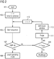
- FIG. 2 shows a flow diagram for an embodiment of the inventive method of starting a gas turbine engine.
- the counting value i is set to 1 and a start-up window is initialised in step 103.
- Initialising the start-up window contains setting starting end points for ramping up the turbine speed and/or the fuel/air mixture in the combustion system.
- the method then proceeds to step 105, in which the start sequence for the gas turbine engine1 is initiated.
- the ignition monitor 9 monitors ignition in the engine. If a successful ignition is detected in step 107, i.e. a successful light-up, the gas turbine engine 1 is transferred into its usual operating mode in step 108.
- step 109 If, in step 107, no successful light-up is detected by the end of the start sequence, it is checked in step 109 whether the counting value i is still smaller than a maximum counting value i -x . In case of no, the method is terminated and a shut down of the gas turbine engine 1 is performed. If the counting value i is still smaller than the maximum counting value i -x a purging signal is output by the processor unit 5 to the gas turbine engine 1 in step 111. It is also output to the window generator 7 and causes the window generator 7 to generate another start-up window which is shifted and/or scaled with respect to the start-up window of the preceding start sequence.
- the shifting and/or scaling may, e.g., follow a preset shift sequence and/or scale sequence.
- the new start-up window is output to the processor unit 5, and 115, the counting value i is increased by one in step 115.
- the method then returns to step 105, in which the new starting sequence with the shifted and/or scaled start-up window is initiated. The described method continues until successful light-up is detected or the maximum counting value i max is reached.
- the inventive method enables the use of shorter start-up windows and hence lower ramp rates but still gives coverage to wide variations in the actual optimum range window. Overall this therefore increases the number of ignition opportunities (sparks from the igniture) in the actual optimum fuel-to-air mixture window for each start-up attempt. Hence, the probability of light-up is increased.
Claims (6)
- Procédé de mise en marche d'un moteur (1) à turbine à gaz au moyen d'une séquence de mise en marche (105) dans laquelle la vitesse de turbine et la distribution de combustible sont coordonnées de sorte à obtenir au niveau d'un dispositif d'allumage un mélange combustible/air permettant un allumage réussi, le moteur (1) à turbine à gaz étant purgé (111) si un allumage réussi ne s'est pas produit à la fin de la séquence de mise en marche (105) et la séquence de mise en marche (105) étant répétée après la purge du moteur (1) à turbine à gaz, caractérisé en ce que l'on fait varier le rapport combustible/air du mélange combustible/air dans une fourchette de rapports combustible/air, la fourchette de rapports combustible/air étant définie par un point initial et un point final de la séquence de mise en marche (105), et en ce que la fourchette de rapports combustible/air est décalée et/ou changée d'échelle quand on répète la séquence de mise en marche (105).
- Procédé selon la revendication 1, caractérisé en ce que l'on fait varier le rapport combustible/air du mélange combustible/air en faisant varier la vitesse de turbine et en ce que l'on décale et/ou change d'échelle les rapports combustible/air en décalant et/ou en changeant d'échelle les vitesses de turbine quand on répète la séquence de mise en marche.
- Procédé selon la revendication 1 ou la revendication 2, caractérisé en ce que le décalage et/ou le changement d'échelle de la fourchette de vitesses de turbine et/ou de la fourchette de rapports combustible/air suit un schéma fixe.
- Procédé selon l'une quelconque des revendications précédentes, caractérisé en ce que la purge (111) et la répétition des séquences de mise en marche (105) s'arrêtent si un état d'arrêt prédéterminé (109) est atteint ou qu'un allumage réussi (107) est détecté.
- Dispositif (3) de régulation permettant de réguler la mise en marche d'un moteur (1) à turbine à gaz comprenant :- un générateur (7) de fenêtres qui est adapté pour produire un signal de fenêtre représentant une fourchette de vitesses de turbine et/ou une fourchette de rapports combustible/air pour laquelle il est le plus probable que la mise en marche se produise ;- une unité formant processeur (5) reliée au générateur (7) de fenêtres pour recevoir le signal de fenêtre et adaptée pour entamer une séquence de mise en marche du moteur (1) à turbine à gaz et pour faire varier la vitesse de turbine et/ou le rapport de mélange d'un mélange combustible/air dans les limites de la fourchette de vitesses de turbine et/ou de la fourchette de rapports combustible/air définie par le signal de fenêtre pendant la séquence de mise en marche, et- un dispositif (9) de contrôle d'allumage permettant de contrôler la réussite de la séquence de mise en marche qui est adapté pour produire un signal d'état représentant la réussite ou l'échec de l'allumage après que la séquence de mise en marche s'est achevée, sachant :- que l'unité formant processeur (5) est reliée au dispositif (9) de contrôle d'allumage pour recevoir le signal d'état après que la séquence de mise en marche s'est achevée ;- que l'unité formant processeur (5) est adaptée pour produire un signal de purge lorsque le signal d'état indique un échec de l'allumage et pour envoyer au moteur (1) à turbine à gaz le signal de purge qui entraîne une purge du moteur (1), etque l'unité formant processeur (5) est adaptée pour entamer une autre séquence de mise en marche après que la purge s'est achevée, caractérisé en ce que le générateur (7) de fenêtres comprend une unité de décalage (11) et/ou une unité de mise à l'échelle (13) qui est/sont reliée(s) à l'unité formant processeur (5) afin de recevoir le signal de purge et qui est/sont adaptée(s) pour décaler ou mettre à l'échelle, respectivement, la fourchette de vitesses de turbine et/ou la fourchette de rapports combustible/air si elle(s) reçoit ou reçoivent le signal de purge.
- Dispositif (3) de régulation selon la revendication 5, caractérisé en ce qu'il comprend un compteur (19) qui est relié à l'unité formant processeur (5) pour recevoir le signal de purge, le compteur (19) étant adapté pour compter le nombre de purges et pour émettre un signal d'arrêt amenant l'unité formant processeur (5) à ne pas entamer une autre séquence de mise en marche lorsqu'un nombre prédéfini de purges a été compté.
Priority Applications (1)
| Application Number | Priority Date | Filing Date | Title |
|---|---|---|---|
| EP07726521.3A EP2021601B1 (fr) | 2006-05-22 | 2007-02-27 | Procédé de démarrage de turbines à gas et dispositif de réglage |
Applications Claiming Priority (3)
| Application Number | Priority Date | Filing Date | Title |
|---|---|---|---|
| EP06010534A EP1860302A1 (fr) | 2006-05-22 | 2006-05-22 | Procédé de démarrage de turbines à gas et dispositif de réglage |
| EP07726521.3A EP2021601B1 (fr) | 2006-05-22 | 2007-02-27 | Procédé de démarrage de turbines à gas et dispositif de réglage |
| PCT/EP2007/051822 WO2007134886A1 (fr) | 2006-05-22 | 2007-02-27 | Procédé et dispositif de commande de démarrage de moteur à turbine à gaz |
Publications (2)
| Publication Number | Publication Date |
|---|---|
| EP2021601A1 EP2021601A1 (fr) | 2009-02-11 |
| EP2021601B1 true EP2021601B1 (fr) | 2016-06-15 |
Family
ID=37400138
Family Applications (2)
| Application Number | Title | Priority Date | Filing Date |
|---|---|---|---|
| EP06010534A Withdrawn EP1860302A1 (fr) | 2006-05-22 | 2006-05-22 | Procédé de démarrage de turbines à gas et dispositif de réglage |
| EP07726521.3A Active EP2021601B1 (fr) | 2006-05-22 | 2007-02-27 | Procédé de démarrage de turbines à gas et dispositif de réglage |
Family Applications Before (1)
| Application Number | Title | Priority Date | Filing Date |
|---|---|---|---|
| EP06010534A Withdrawn EP1860302A1 (fr) | 2006-05-22 | 2006-05-22 | Procédé de démarrage de turbines à gas et dispositif de réglage |
Country Status (4)
| Country | Link |
|---|---|
| US (1) | US8590317B2 (fr) |
| EP (2) | EP1860302A1 (fr) |
| CN (1) | CN101449039B (fr) |
| WO (1) | WO2007134886A1 (fr) |
Families Citing this family (16)
| Publication number | Priority date | Publication date | Assignee | Title |
|---|---|---|---|---|
| ITMI20080164A1 (it) * | 2008-02-04 | 2009-08-05 | Nuovo Pignone Spa | Metodo per l'avviamento di una turbina a gas |
| US8467949B2 (en) * | 2009-05-29 | 2013-06-18 | Honeywell International Inc. | Methods and systems for turbine line replaceable unit fault detection and isolation during engine startup |
| IT1396516B1 (it) | 2009-11-27 | 2012-12-14 | Nuovo Pignone Spa | Metodo di controllo di modo basato su temperatura di scarico per turbina a gas e turbina a gas |
| IT1396514B1 (it) | 2009-11-27 | 2012-12-14 | Nuovo Pignone Spa | Metodo di controllo di turbina basato su rapporto tra temperatura di scarico e pressione di turbina |
| IT1396517B1 (it) | 2009-11-27 | 2012-12-14 | Nuovo Pignone Spa | Metodo di controllo di modo basato su temperatura di scarico per turbina a gas e turbina a gas |
| IT1396515B1 (it) | 2009-11-27 | 2012-12-14 | Nuovo Pignone Spa | Soglia basata su temperatura di scarico per metodo di controllo e turbina |
| US9541005B2 (en) * | 2012-09-28 | 2017-01-10 | Pratt & Whitney Canada Corp. | Adaptive fuel manifold filling function for improved engine start |
| CN102979626B (zh) * | 2012-11-29 | 2016-09-28 | 哈尔滨东安发动机(集团)有限公司 | 航空发动机高压空气起动装置 |
| CN103018050B (zh) * | 2012-11-29 | 2017-06-27 | 哈尔滨东安发动机(集团)有限公司 | 航空发动机空气带转试验的送气结构 |
| CN102980774B (zh) * | 2012-11-29 | 2017-08-08 | 哈尔滨东安发动机(集团)有限公司 | 航空发动机空气带转试验器调整机构 |
| US20140165586A1 (en) * | 2012-12-17 | 2014-06-19 | United Technologies Corporation | Turbine start method |
| EP2762687A1 (fr) | 2013-02-01 | 2014-08-06 | Siemens Aktiengesellschaft | Procédé de démarrage d'un système de combustion |
| CN104329173B (zh) * | 2014-09-11 | 2016-05-25 | 中国科学院工程热物理研究所 | 一种燃气轮机燃料与空气混合比的控制方法及装置 |
| CN104481704B (zh) * | 2014-12-10 | 2016-02-10 | 中国科学院工程热物理研究所 | 一种实现燃气轮机起动过程中燃料实时控制方法及装置 |
| US10429154B2 (en) | 2016-08-29 | 2019-10-01 | Rolls-Royce North American Technologies Inc. | Energy weapon having a fast start turbine for a high power generator |
| CN108150295A (zh) * | 2017-11-22 | 2018-06-12 | 北京动力机械研究所 | 一种无人机用发动机起动控制方法 |
Family Cites Families (8)
| Publication number | Priority date | Publication date | Assignee | Title |
|---|---|---|---|---|
| US3310937A (en) * | 1965-08-20 | 1967-03-28 | Avco Corp | Automatic starting control system for gas turbine engines |
| US5101619A (en) * | 1990-02-20 | 1992-04-07 | United Technologies Corporation | Method for correcting a hot start condition |
| US5107674A (en) * | 1990-03-30 | 1992-04-28 | General Electric Company | Control for a gas turbine engine |
| US6766647B2 (en) * | 2001-07-27 | 2004-07-27 | Elliott Energy Systems, Inc. | Method for ignition and start up of a turbogenerator |
| AU2003202136A1 (en) * | 2002-01-09 | 2003-07-30 | Ebara Corporation | A gas turbine apparatus and a starting method thereof |
| US6968699B2 (en) * | 2003-05-08 | 2005-11-29 | General Electric Company | Sector staging combustor |
| US7509812B2 (en) * | 2004-08-20 | 2009-03-31 | Hamilton Sundstrand Corporation | Dual ignition system for a gas turbine engine |
| US7386982B2 (en) * | 2004-10-26 | 2008-06-17 | General Electric Company | Method and system for detecting ignition failure in a gas turbine engine |
-
2006
- 2006-05-22 EP EP06010534A patent/EP1860302A1/fr not_active Withdrawn
-
2007
- 2007-02-27 EP EP07726521.3A patent/EP2021601B1/fr active Active
- 2007-02-27 CN CN200780018665.3A patent/CN101449039B/zh active Active
- 2007-02-27 WO PCT/EP2007/051822 patent/WO2007134886A1/fr active Application Filing
- 2007-02-27 US US12/227,470 patent/US8590317B2/en active Active
Also Published As
| Publication number | Publication date |
|---|---|
| EP2021601A1 (fr) | 2009-02-11 |
| WO2007134886A1 (fr) | 2007-11-29 |
| US8590317B2 (en) | 2013-11-26 |
| EP1860302A1 (fr) | 2007-11-28 |
| US20100293960A1 (en) | 2010-11-25 |
| CN101449039A (zh) | 2009-06-03 |
| CN101449039B (zh) | 2012-03-21 |
Similar Documents
| Publication | Publication Date | Title |
|---|---|---|
| EP2021601B1 (fr) | Procédé de démarrage de turbines à gas et dispositif de réglage | |
| US7878004B2 (en) | Method and device for optimizing a light-up procedure of a gas turbine engine | |
| RU2467192C1 (ru) | Способ запуска газотурбинного двигателя | |
| US4350008A (en) | Method of starting turbine engines | |
| US7840333B2 (en) | Event-driven starter controller | |
| US7861534B2 (en) | Method of starting turbine engine from low engine speed | |
| EP2085577B1 (fr) | Procédé pour le démarrage d'une turbine à gaz | |
| US20040237535A1 (en) | Method of operating a gas turbine | |
| US10094292B2 (en) | Method of acceleration control during APU starting | |
| EP2428663B1 (fr) | Procédés et dispositifs de test de couple à faible vitesse d'un rotor dans une turbomachine | |
| US6834226B2 (en) | Multiple control loop acceleration of turboalternator after reaching self-sustaining speed previous to reaching synchronous speed | |
| US9518512B2 (en) | Method for starting a turbomachine | |
| EP0925444A1 (fr) | Systeme et procede de demarrage de turbines a gaz | |
| RU2616739C2 (ru) | Способ запуска системы сгорания | |
| JP4218778B2 (ja) | ガスタービンの起動制御方法 | |
| JP2798533B2 (ja) | ガスタービンの始動制御装置 | |
| RU2171904C2 (ru) | Способ запуска и поддержания оборотов газотурбинного авиационного двигателя со свободной турбиной, работающего по парогазовому циклу | |
| JP3151692B2 (ja) | ガスタービンの起動装置 | |
| JP2009250208A (ja) | 一軸コンバインドプラントの再起動方法及び再起動装置 | |
| JP2003214188A (ja) | ガスタービン装置 |
Legal Events
| Date | Code | Title | Description |
|---|---|---|---|
| PUAI | Public reference made under article 153(3) epc to a published international application that has entered the european phase |
Free format text: ORIGINAL CODE: 0009012 |
|
| 17P | Request for examination filed |
Effective date: 20081007 |
|
| AK | Designated contracting states |
Kind code of ref document: A1 Designated state(s): AT BE BG CH CY CZ DE DK EE ES FI FR GB GR HU IE IS IT LI LT LU LV MC NL PL PT RO SE SI SK TR |
|
| AX | Request for extension of the european patent |
Extension state: AL BA HR MK RS |
|
| 17Q | First examination report despatched |
Effective date: 20090423 |
|
| DAX | Request for extension of the european patent (deleted) | ||
| RBV | Designated contracting states (corrected) |
Designated state(s): DE ES FR GB IT |
|
| RAP1 | Party data changed (applicant data changed or rights of an application transferred) |
Owner name: SIEMENS AKTIENGESELLSCHAFT |
|
| REG | Reference to a national code |
Ref country code: DE Ref legal event code: R079 Ref document number: 602007046650 Country of ref document: DE Free format text: PREVIOUS MAIN CLASS: F02C0007260000 Ipc: F02C0009260000 |
|
| RIC1 | Information provided on ipc code assigned before grant |
Ipc: F02C 9/26 20060101AFI20151118BHEP |
|
| GRAP | Despatch of communication of intention to grant a patent |
Free format text: ORIGINAL CODE: EPIDOSNIGR1 |
|
| INTG | Intention to grant announced |
Effective date: 20160104 |
|
| GRAS | Grant fee paid |
Free format text: ORIGINAL CODE: EPIDOSNIGR3 |
|
| GRAA | (expected) grant |
Free format text: ORIGINAL CODE: 0009210 |
|
| AK | Designated contracting states |
Kind code of ref document: B1 Designated state(s): DE ES FR GB IT |
|
| REG | Reference to a national code |
Ref country code: GB Ref legal event code: FG4D |
|
| REG | Reference to a national code |
Ref country code: DE Ref legal event code: R096 Ref document number: 602007046650 Country of ref document: DE |
|
| REG | Reference to a national code |
Ref country code: FR Ref legal event code: PLFP Year of fee payment: 11 |
|
| PG25 | Lapsed in a contracting state [announced via postgrant information from national office to epo] |
Ref country code: ES Free format text: LAPSE BECAUSE OF FAILURE TO SUBMIT A TRANSLATION OF THE DESCRIPTION OR TO PAY THE FEE WITHIN THE PRESCRIBED TIME-LIMIT Effective date: 20160615 |
|
| REG | Reference to a national code |
Ref country code: DE Ref legal event code: R097 Ref document number: 602007046650 Country of ref document: DE |
|
| PLBE | No opposition filed within time limit |
Free format text: ORIGINAL CODE: 0009261 |
|
| STAA | Information on the status of an ep patent application or granted ep patent |
Free format text: STATUS: NO OPPOSITION FILED WITHIN TIME LIMIT |
|
| 26N | No opposition filed |
Effective date: 20170316 |
|
| REG | Reference to a national code |
Ref country code: FR Ref legal event code: PLFP Year of fee payment: 12 |
|
| REG | Reference to a national code |
Ref country code: DE Ref legal event code: R081 Ref document number: 602007046650 Country of ref document: DE Owner name: SIEMENS ENERGY GLOBAL GMBH & CO. KG, DE Free format text: FORMER OWNER: SIEMENS AKTIENGESELLSCHAFT, 80333 MUENCHEN, DE |
|
| REG | Reference to a national code |
Ref country code: GB Ref legal event code: 732E Free format text: REGISTERED BETWEEN 20220811 AND 20220817 |
|
| PGFP | Annual fee paid to national office [announced via postgrant information from national office to epo] |
Ref country code: FR Payment date: 20230221 Year of fee payment: 17 |
|
| PGFP | Annual fee paid to national office [announced via postgrant information from national office to epo] |
Ref country code: IT Payment date: 20230221 Year of fee payment: 17 |
|
| PGFP | Annual fee paid to national office [announced via postgrant information from national office to epo] |
Ref country code: DE Payment date: 20240228 Year of fee payment: 18 Ref country code: GB Payment date: 20240220 Year of fee payment: 18 |