EP2020827B1 - Shielding system for microwave ovens and microwave oven using this shielding system. - Google Patents
Shielding system for microwave ovens and microwave oven using this shielding system. Download PDFInfo
- Publication number
- EP2020827B1 EP2020827B1 EP07111628.9A EP07111628A EP2020827B1 EP 2020827 B1 EP2020827 B1 EP 2020827B1 EP 07111628 A EP07111628 A EP 07111628A EP 2020827 B1 EP2020827 B1 EP 2020827B1
- Authority
- EP
- European Patent Office
- Prior art keywords
- shielding system
- layer
- conductors
- microwave
- shielding
- Prior art date
- Legal status (The legal status is an assumption and is not a legal conclusion. Google has not performed a legal analysis and makes no representation as to the accuracy of the status listed.)
- Not-in-force
Links
Images
Classifications
-
- H—ELECTRICITY
- H05—ELECTRIC TECHNIQUES NOT OTHERWISE PROVIDED FOR
- H05B—ELECTRIC HEATING; ELECTRIC LIGHT SOURCES NOT OTHERWISE PROVIDED FOR; CIRCUIT ARRANGEMENTS FOR ELECTRIC LIGHT SOURCES, IN GENERAL
- H05B6/00—Heating by electric, magnetic or electromagnetic fields
- H05B6/64—Heating using microwaves
- H05B6/76—Prevention of microwave leakage, e.g. door sealings
- H05B6/766—Microwave radiation screens for windows
-
- H—ELECTRICITY
- H05—ELECTRIC TECHNIQUES NOT OTHERWISE PROVIDED FOR
- H05B—ELECTRIC HEATING; ELECTRIC LIGHT SOURCES NOT OTHERWISE PROVIDED FOR; CIRCUIT ARRANGEMENTS FOR ELECTRIC LIGHT SOURCES, IN GENERAL
- H05B6/00—Heating by electric, magnetic or electromagnetic fields
- H05B6/64—Heating using microwaves
- H05B6/6414—Aspects relating to the door of the microwave heating apparatus
-
- H—ELECTRICITY
- H05—ELECTRIC TECHNIQUES NOT OTHERWISE PROVIDED FOR
- H05B—ELECTRIC HEATING; ELECTRIC LIGHT SOURCES NOT OTHERWISE PROVIDED FOR; CIRCUIT ARRANGEMENTS FOR ELECTRIC LIGHT SOURCES, IN GENERAL
- H05B6/00—Heating by electric, magnetic or electromagnetic fields
- H05B6/64—Heating using microwaves
- H05B6/647—Aspects related to microwave heating combined with other heating techniques
- H05B6/6488—Aspects related to microwave heating combined with other heating techniques combined with induction heating
-
- H—ELECTRICITY
- H05—ELECTRIC TECHNIQUES NOT OTHERWISE PROVIDED FOR
- H05B—ELECTRIC HEATING; ELECTRIC LIGHT SOURCES NOT OTHERWISE PROVIDED FOR; CIRCUIT ARRANGEMENTS FOR ELECTRIC LIGHT SOURCES, IN GENERAL
- H05B6/00—Heating by electric, magnetic or electromagnetic fields
- H05B6/64—Heating using microwaves
- H05B6/76—Prevention of microwave leakage, e.g. door sealings
-
- Y—GENERAL TAGGING OF NEW TECHNOLOGICAL DEVELOPMENTS; GENERAL TAGGING OF CROSS-SECTIONAL TECHNOLOGIES SPANNING OVER SEVERAL SECTIONS OF THE IPC; TECHNICAL SUBJECTS COVERED BY FORMER USPC CROSS-REFERENCE ART COLLECTIONS [XRACs] AND DIGESTS
- Y10—TECHNICAL SUBJECTS COVERED BY FORMER USPC
- Y10T—TECHNICAL SUBJECTS COVERED BY FORMER US CLASSIFICATION
- Y10T428/00—Stock material or miscellaneous articles
- Y10T428/24—Structurally defined web or sheet [e.g., overall dimension, etc.]
- Y10T428/24058—Structurally defined web or sheet [e.g., overall dimension, etc.] including grain, strips, or filamentary elements in respective layers or components in angular relation
Definitions
- the present invention relates to a shielding system for microwave ovens. It is well known in the art of microwave ovens the need of providing shielding systems, particularly in connection with glass in the oven door, which shall allow the user to look into the cooking cavity of the oven without any leakage of microwaves through the transparent door.
- microwave shielding systems particularly for microwave ovens having an electromagnetic induction coil provided outside the cooking cavity, adjacent the bottom wall thereof.
- an oven is disclosed by EP-A-464390 .
- the shielding system must act as a reflective boundary for microwaves (typically in the range of 2,45 GHz) and be substantially "transparent" to the electromagnetic waves (typically about 20 to 30 kHz) responsible for induction heating.
- large losses in the shielding system due to eddy current loss in the surface portion of the shielding system is preferably avoided.
- the use of a non-magnetic metal mesh within a predetermined size range as microwave shielding system solved the above technical problem.
- EP-A2-0742413 discloses a shielding system according to the preamble of attached claim 1.
- JP 54146174 discloses a seeing through window for door of the microwave oven.
- One object of the present invention is to provide a shielding system that does not present the above disadvantages and that has a low cost.
- Another object of the present invention is to provide a shielding device that enables induction cooking inside a microwave oven by stopping microwave leakage from the cavity and letting lower frequency induction field passing through into the cavity to achieve both microwave and induction cooking within the same unit of cavity.
- Each layer preferably comprises a plurality of parallel metal wires, connected at one end and grounded (like a fork). These two layers of wires are perpendicular, where with this term we mean that the wire are disposed at an angle equal or close to 90°. Other values of angle between the wires can be used, these being considered within the scope of the invention, but an angle of or close to 90° is considered the preferred one.
- the insulation between the two layers can be obtained by placing them at a certain low distance, for instance between 1 and 2 mm.
- This configuration in which the shielding structure of parallel wires has to present a sufficient stiffness, allows airflow through the shielding system, e.g. for forced convection system or cavity ventilation. This would avoid the use of small holes and perforations that block microwave leakage and allow airflow through.
- the solution according to the invention means a significant reduction of the resistance for the airflow.
- the two metal wire layers are supported by the two surfaces of a transparent sheet, for instance of glass or polymeric material.
- a transparent sheet for instance of glass or polymeric material.
- an auxiliary transparent sheet of glass can be used, having a conductive and optically transparent coating (e.g. heat reflecting glass).
- This embodiment provides an excellent "see through" window for a microwave oven.
- the transparent support sheet may be thinner than the support layer used according to prior art, since the heating of metal wires according to the invention is reduced.
- a two-side printed circuit board can be used to build up the two metal wire layers.
- the plurality of parallel conductors are obtained as conductive pathways or traces etched from copper sheets laminated onto each face of the PCB etching the pathways on the two sides in a perpendicular fashion.
- the connection of conductors to the ground is made easier and a distributed connection to ground can be achieved.
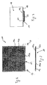
- a shielding device comprising a transparent glass sheet 12, preferably 1-2 mm thick, having two opposite faces 12a and 12b. On such faces are supported two comb-shaped layers 14a and 14b each constituted by a plurality of metal parallel wires electrically connected to ground G.
- the metal wires for instance made of copper, have a diameter preferably comprised between 0.2 and 2 mm. The distance between each two adjacent wire is preferably comprised between 1 and 4 mm.
- the metal wires of the layer 14a placed on face 12a are perpendicular to the metal wires of the layer 14b placed on face 12b of the glass sheet.
- the shielding device 10 When the shielding device 10 is installed in a microwave oven, for instance to the microwave oven door, the device shall be attached to the cavity in a known fashion to block microwave leakage at the edge of the device, e.g. by galvanic contact, capacitive sealing or quarter-wavelength choke. In the embodiment where a two-side printed circuit board is used, a distributed circumferential ground contact is used as well.)
- FIG 3 it is shown a particular use of the shielding device 10 in connection with the bottom wall 16 of a microwave oven cavity 18.
- the bottom wall 16 presents a circular central hole 16a and a glass plate 20 covers it.
- Below the bottom wall coaxial with the hole 16a it is placed the shielding device 10 that is above and adjacent an induction cooker coil 22. Therefore there is no leakage of microwaves through the bottom wall 16 despite the presence of the hole 16a, while there is negligible dissipation of energy and therefore negligible heating of the device 10 by means of eddy currents when the induction cooker coil 22 is being operated.
Landscapes
- Physics & Mathematics (AREA)
- Electromagnetism (AREA)
- Electric Ovens (AREA)
Description
- The present invention relates to a shielding system for microwave ovens. It is well known in the art of microwave ovens the need of providing shielding systems, particularly in connection with glass in the oven door, which shall allow the user to look into the cooking cavity of the oven without any leakage of microwaves through the transparent door.
- There are also other uses of microwave shielding systems, particularly for microwave ovens having an electromagnetic induction coil provided outside the cooking cavity, adjacent the bottom wall thereof. Such an oven is disclosed by
EP-A-464390 - This known system is not completely satisfactory from an energy loss point of view. As a matter of fact the mesh is heated both by microwave absorption and by electromagnetic induction. In a connected mesh, microwave losses can be rather substantial due to the fact that it is possible to have a multitude of different resonant pathways in the connected mesh. Such heating causes a deformation and therefore such deformation has to be absorbed by one or more insulating layers on which the mesh is placed.
-
EP-A2-0742413 discloses a shielding system according to the preamble of attached claim 1.JP 54146174 - One object of the present invention is to provide a shielding system that does not present the above disadvantages and that has a low cost.
- Another object of the present invention is to provide a shielding device that enables induction cooking inside a microwave oven by stopping microwave leakage from the cavity and letting lower frequency induction field passing through into the cavity to achieve both microwave and induction cooking within the same unit of cavity.
- The above objects are reached thanks to a shielding system and to a microwave oven having the features listed in the appended claims.
- The applicant has discovered that by using a shielding system comprising two layers of perpendicular parallel metal conductors insulated from each other and grounded, the results in term of microwave shielding and/or loss due to eddy currents are surprisingly good. Each layer preferably comprises a plurality of parallel metal wires, connected at one end and grounded (like a fork). These two layers of wires are perpendicular, where with this term we mean that the wire are disposed at an angle equal or close to 90°. Other values of angle between the wires can be used, these being considered within the scope of the invention, but an angle of or close to 90° is considered the preferred one.
- The insulation between the two layers can be obtained by placing them at a certain low distance, for instance between 1 and 2 mm. This configuration, in which the shielding structure of parallel wires has to present a sufficient stiffness, allows airflow through the shielding system, e.g. for forced convection system or cavity ventilation. This would avoid the use of small holes and perforations that block microwave leakage and allow airflow through. The solution according to the invention means a significant reduction of the resistance for the airflow.
- According to another embodiment of the invention, the two metal wire layers are supported by the two surfaces of a transparent sheet, for instance of glass or polymeric material. In order to increase microwave leakage attenuation, an auxiliary transparent sheet of glass can be used, having a conductive and optically transparent coating (e.g. heat reflecting glass). This embodiment provides an excellent "see through" window for a microwave oven. Moreover the transparent support sheet may be thinner than the support layer used according to prior art, since the heating of metal wires according to the invention is reduced.
- According to a further embodiment of the invention, a two-side printed circuit board (PCB) can be used to build up the two metal wire layers. In this embodiment the plurality of parallel conductors are obtained as conductive pathways or traces etched from copper sheets laminated onto each face of the PCB etching the pathways on the two sides in a perpendicular fashion. According to this embodiment the connection of conductors to the ground is made easier and a distributed connection to ground can be achieved.
- Further advantages and features according to the present invention will be clear from the following detailed description, provided by way of a non-limiting example, with reference to the attached drawings in which:
-
figure 1 is a schematic frontal view of a shielding device according to the present invention, -
figure 2 is a cross section of the device offigure 1 , and -
figure 3 is a schematic sectional view of a microwave oven according to the invention in which the shielding device offigure 1-2 is used in association with an electromagnetic induction coil. - With reference to the drawings, with 10 is indicated a shielding device comprising a
transparent glass sheet 12, preferably 1-2 mm thick, having two opposite faces 12a and 12b. On such faces are supported two comb-shaped layers 14a and 14b each constituted by a plurality of metal parallel wires electrically connected to ground G. The metal wires, for instance made of copper, have a diameter preferably comprised between 0.2 and 2 mm. The distance between each two adjacent wire is preferably comprised between 1 and 4 mm. The metal wires of the layer 14a placed on face 12a are perpendicular to the metal wires of the layer 14b placed on face 12b of the glass sheet. Therefore by looking through theglass sheet 12, as infigure 1 , there seems to be an echelon-shaped crossing of metal wires, while the glass sheet acts as an electric insulator. When the shielding device 10 is installed in a microwave oven, for instance to the microwave oven door, the device shall be attached to the cavity in a known fashion to block microwave leakage at the edge of the device, e.g. by galvanic contact, capacitive sealing or quarter-wavelength choke. In the embodiment where a two-side printed circuit board is used, a distributed circumferential ground contact is used as well.) - In
figure 3 it is shown a particular use of the shielding device 10 in connection with thebottom wall 16 of amicrowave oven cavity 18. Thebottom wall 16 presents a circular central hole 16a and aglass plate 20 covers it. Below the bottom wall, coaxial with the hole 16a it is placed the shielding device 10 that is above and adjacent aninduction cooker coil 22. Therefore there is no leakage of microwaves through thebottom wall 16 despite the presence of the hole 16a, while there is negligible dissipation of energy and therefore negligible heating of the device 10 by means of eddy currents when theinduction cooker coil 22 is being operated.
Claims (8)
- Shielding system (10) for microwave ovens, comprising a first layer (14a) of parallel conductors and a second layer (14b) of parallel conductors substantially perpendicular to the conductors of the first layer and electrically insulated therefrom, characterised in that the conductors of each layer (14a, 14b) are grounded.
- Shielding system according to claim 1, wherein each layer (14a, 14b) presents a plurality of parallel metal wires connected at one end and grounded.
- Shielding system according to claim 1 or 2, wherein the conductors of each layer (14a, 14b) are placed on opposite sides (12a, 12b) of an insulating plate (12).
- Shielding system according to claim 3, wherein the conductors of each layer (14a, 14b) are built as traces of a two-side printed circuit board.
- Shielding system according to claim 1, wherein the conductors of the first layer (14a) and the conductors of the second layer (14b) are electrically insulated for high frequency.
- Microwave oven comprising a cooking cavity (18), characterised in that it comprises a shielding system (10) according to one of the preceding claims and associated to one or more walls of the oven cavity (18).
- Microwave oven according to claim 6, wherein the shielding system (10) is associated to the transparent door of the oven.
- Microwave oven according to claim 6, comprising an electromagnetic induction coil (22) placed outside the cavity (18) adjacent a bottom wall (16) thereof, wherein the shielding system (10) is associated to one aperture (16a) in the bottom wall (16) of the cavity (18).
Priority Applications (3)
| Application Number | Priority Date | Filing Date | Title |
|---|---|---|---|
| EP07111628.9A EP2020827B1 (en) | 2007-07-03 | 2007-07-03 | Shielding system for microwave ovens and microwave oven using this shielding system. |
| ES07111628T ES2436106T3 (en) | 2007-07-03 | 2007-07-03 | Shielding system for microwave and microwave oven that uses this shielding system |
| US12/166,368 US8772686B2 (en) | 2007-07-03 | 2008-07-02 | Shielding system for microwave ovens and microwave oven using this shielding system |
Applications Claiming Priority (1)
| Application Number | Priority Date | Filing Date | Title |
|---|---|---|---|
| EP07111628.9A EP2020827B1 (en) | 2007-07-03 | 2007-07-03 | Shielding system for microwave ovens and microwave oven using this shielding system. |
Publications (2)
| Publication Number | Publication Date |
|---|---|
| EP2020827A1 EP2020827A1 (en) | 2009-02-04 |
| EP2020827B1 true EP2020827B1 (en) | 2013-10-23 |
Family
ID=38596101
Family Applications (1)
| Application Number | Title | Priority Date | Filing Date |
|---|---|---|---|
| EP07111628.9A Not-in-force EP2020827B1 (en) | 2007-07-03 | 2007-07-03 | Shielding system for microwave ovens and microwave oven using this shielding system. |
Country Status (3)
| Country | Link |
|---|---|
| US (1) | US8772686B2 (en) |
| EP (1) | EP2020827B1 (en) |
| ES (1) | ES2436106T3 (en) |
Cited By (1)
| Publication number | Priority date | Publication date | Assignee | Title |
|---|---|---|---|---|
| EP3488149B1 (en) * | 2016-08-22 | 2023-09-27 | Samsung Electronics Co., Ltd. | Cooking appliance, door for cooking appliance |
Families Citing this family (9)
| Publication number | Priority date | Publication date | Assignee | Title |
|---|---|---|---|---|
| EP3269204B1 (en) | 2015-03-09 | 2018-09-26 | Whirlpool Corporation | Microwave oven having door with transparent panel |
| WO2017030921A1 (en) * | 2015-08-14 | 2017-02-23 | Graphic Packaging International, Inc. | Automatically reconfigurable microwave interactive material |
| CN107218638B (en) * | 2017-06-08 | 2019-09-20 | 广东美的厨房电器制造有限公司 | A microwave shielding plate and microwave cooking device |
| DE102017218832A1 (en) | 2017-10-23 | 2019-04-25 | BSH Hausgeräte GmbH | Door for a household microwave oven |
| KR102961247B1 (en) * | 2020-02-24 | 2026-05-08 | 엘지전자 주식회사 | Cooking appliance |
| KR102329538B1 (en) | 2020-04-21 | 2021-11-23 | 엘지전자 주식회사 | Cooking appliance |
| KR102946403B1 (en) * | 2020-09-22 | 2026-04-01 | 엘지전자 주식회사 | Cooking appliance |
| US12615699B2 (en) | 2021-10-28 | 2026-04-28 | Lg Electronics Inc. | Cooking appliance |
| JP2026047573A (en) * | 2024-09-04 | 2026-03-16 | シャープ株式会社 | heating cooker |
Family Cites Families (11)
| Publication number | Priority date | Publication date | Assignee | Title |
|---|---|---|---|---|
| GB752206A (en) * | 1953-11-12 | 1956-07-04 | Raytheon Mfg Co | Improvements in or relating to high frequency dielectric heating apparatus |
| JPS6040570B2 (en) * | 1978-05-08 | 1985-09-11 | シャープ株式会社 | Microwave oven door transparent window structure |
| FR2484397A1 (en) * | 1980-06-16 | 1981-12-18 | Trois Fontaines Verreries | Safety glass for microwave appts. - with impermeable conducting barrier formed by metallic mesh |
| JPS58127404A (en) * | 1982-01-25 | 1983-07-29 | Hitachi Metals Ltd | Broad band two-terminal isolator |
| JPH0465097A (en) | 1990-07-05 | 1992-03-02 | Mitsubishi Electric Home Appliance Co Ltd | High frequency heating cooler with electromagnetic induction heater |
| US5300746A (en) * | 1990-11-08 | 1994-04-05 | Advanced Deposition Technologies, Inc. | Metallized microwave diffuser films |
| GB2262208A (en) * | 1991-12-05 | 1993-06-09 | Toppan Printing Co Ltd | Microwave oven door panel structure |
| KR0176773B1 (en) * | 1995-05-09 | 1999-05-15 | 구자홍 | Microwave oven having induction heater and its control method |
| LU90412B1 (en) * | 1999-07-02 | 2001-01-03 | Cabinet Erman | Coating process and products resulting from the coating process |
| DE10250298A1 (en) * | 2002-10-29 | 2004-06-03 | Schott Glas | Door with window for microwave ovens |
| JP2005175335A (en) * | 2003-12-15 | 2005-06-30 | Nippon Electric Glass Co Ltd | Electromagnetic wave shielding glass plate |
-
2007
- 2007-07-03 ES ES07111628T patent/ES2436106T3/en active Active
- 2007-07-03 EP EP07111628.9A patent/EP2020827B1/en not_active Not-in-force
-
2008
- 2008-07-02 US US12/166,368 patent/US8772686B2/en not_active Expired - Fee Related
Cited By (1)
| Publication number | Priority date | Publication date | Assignee | Title |
|---|---|---|---|---|
| EP3488149B1 (en) * | 2016-08-22 | 2023-09-27 | Samsung Electronics Co., Ltd. | Cooking appliance, door for cooking appliance |
Also Published As
| Publication number | Publication date |
|---|---|
| EP2020827A1 (en) | 2009-02-04 |
| US20090008386A1 (en) | 2009-01-08 |
| US8772686B2 (en) | 2014-07-08 |
| ES2436106T3 (en) | 2013-12-27 |
Similar Documents
| Publication | Publication Date | Title |
|---|---|---|
| US8772686B2 (en) | Shielding system for microwave ovens and microwave oven using this shielding system | |
| US8502125B2 (en) | Microwave oven door with a waves chokes system | |
| US11729872B2 (en) | Microwave oven having door with transparent panel | |
| EP3306202B1 (en) | Cooking appliance | |
| EP3331114B1 (en) | Connection system for electrical, signal and/or data installations | |
| JP2016509391A (en) | Floating connector shield | |
| KR0185774B1 (en) | Microwave oven including antenna for radiating microwave | |
| US4358653A (en) | Combination microwave oven | |
| KR100521089B1 (en) | Combined Induction heating cooker | |
| EP3441678B1 (en) | Cooking hob with at least one heating power transferring element | |
| Tomiyasu | Minimizing radiation leakage from microwave ovens | |
| KR102965964B1 (en) | Cooking device | |
| CA1114453A (en) | Combination microwave and resistively heated oven | |
| CN101826390A (en) | Structure of microwave oven transformer | |
| EP3930424B1 (en) | Support device for an induction coil | |
| RU2821816C1 (en) | Screen | |
| EP3537468B1 (en) | Magnetron filter board for microwave oven | |
| JP3005395B2 (en) | High frequency heating equipment | |
| JP2017022682A (en) | Noise filter | |
| JP2005026092A (en) | High frequency heating device | |
| HK1146185A (en) | A microwave oven door with a wave chokes system | |
| KR19980025604A (en) | Microwave | |
| KR19990030589U (en) | Microwave quartz heater assembly device | |
| JPS6021478B2 (en) | High frequency heating device |
Legal Events
| Date | Code | Title | Description |
|---|---|---|---|
| PUAI | Public reference made under article 153(3) epc to a published international application that has entered the european phase |
Free format text: ORIGINAL CODE: 0009012 |
|
| AK | Designated contracting states |
Kind code of ref document: A1 Designated state(s): AT BE BG CH CY CZ DE DK EE ES FI FR GB GR HU IE IS IT LI LT LU LV MC MT NL PL PT RO SE SI SK TR |
|
| AX | Request for extension of the european patent |
Extension state: AL BA HR MK RS |
|
| 17P | Request for examination filed |
Effective date: 20090721 |
|
| 17Q | First examination report despatched |
Effective date: 20090814 |
|
| AKX | Designation fees paid |
Designated state(s): DE ES FR GB IT SE |
|
| REG | Reference to a national code |
Ref country code: DE Ref legal event code: R079 Ref document number: 602007033431 Country of ref document: DE Free format text: PREVIOUS MAIN CLASS: H05B0006760000 Ipc: H05B0006640000 |
|
| GRAP | Despatch of communication of intention to grant a patent |
Free format text: ORIGINAL CODE: EPIDOSNIGR1 |
|
| RIC1 | Information provided on ipc code assigned before grant |
Ipc: H05B 6/76 20060101ALI20130618BHEP Ipc: H05B 6/64 20060101AFI20130618BHEP |
|
| INTG | Intention to grant announced |
Effective date: 20130722 |
|
| GRAS | Grant fee paid |
Free format text: ORIGINAL CODE: EPIDOSNIGR3 |
|
| GRAA | (expected) grant |
Free format text: ORIGINAL CODE: 0009210 |
|
| AK | Designated contracting states |
Kind code of ref document: B1 Designated state(s): DE ES FR GB IT SE |
|
| REG | Reference to a national code |
Ref country code: GB Ref legal event code: FG4D |
|
| REG | Reference to a national code |
Ref country code: SE Ref legal event code: TRGR |
|
| REG | Reference to a national code |
Ref country code: DE Ref legal event code: R096 Ref document number: 602007033431 Country of ref document: DE Effective date: 20131219 |
|
| REG | Reference to a national code |
Ref country code: ES Ref legal event code: FG2A Ref document number: 2436106 Country of ref document: ES Kind code of ref document: T3 Effective date: 20131227 |
|
| REG | Reference to a national code |
Ref country code: DE Ref legal event code: R097 Ref document number: 602007033431 Country of ref document: DE |
|
| PLBE | No opposition filed within time limit |
Free format text: ORIGINAL CODE: 0009261 |
|
| STAA | Information on the status of an ep patent application or granted ep patent |
Free format text: STATUS: NO OPPOSITION FILED WITHIN TIME LIMIT |
|
| 26N | No opposition filed |
Effective date: 20140724 |
|
| REG | Reference to a national code |
Ref country code: DE Ref legal event code: R097 Ref document number: 602007033431 Country of ref document: DE Effective date: 20140724 |
|
| REG | Reference to a national code |
Ref country code: FR Ref legal event code: PLFP Year of fee payment: 10 |
|
| PGFP | Annual fee paid to national office [announced via postgrant information from national office to epo] |
Ref country code: ES Payment date: 20160613 Year of fee payment: 10 Ref country code: GB Payment date: 20160629 Year of fee payment: 10 |
|
| PGFP | Annual fee paid to national office [announced via postgrant information from national office to epo] |
Ref country code: SE Payment date: 20160712 Year of fee payment: 10 |
|
| REG | Reference to a national code |
Ref country code: FR Ref legal event code: PLFP Year of fee payment: 11 |
|
| REG | Reference to a national code |
Ref country code: SE Ref legal event code: EUG |
|
| GBPC | Gb: european patent ceased through non-payment of renewal fee |
Effective date: 20170703 |
|
| PG25 | Lapsed in a contracting state [announced via postgrant information from national office to epo] |
Ref country code: GB Free format text: LAPSE BECAUSE OF NON-PAYMENT OF DUE FEES Effective date: 20170703 Ref country code: SE Free format text: LAPSE BECAUSE OF NON-PAYMENT OF DUE FEES Effective date: 20170704 |
|
| REG | Reference to a national code |
Ref country code: FR Ref legal event code: PLFP Year of fee payment: 12 |
|
| REG | Reference to a national code |
Ref country code: ES Ref legal event code: FD2A Effective date: 20181112 |
|
| PG25 | Lapsed in a contracting state [announced via postgrant information from national office to epo] |
Ref country code: ES Free format text: LAPSE BECAUSE OF NON-PAYMENT OF DUE FEES Effective date: 20170704 |
|
| P01 | Opt-out of the competence of the unified patent court (upc) registered |
Effective date: 20230522 |
|
| PGFP | Annual fee paid to national office [announced via postgrant information from national office to epo] |
Ref country code: DE Payment date: 20240731 Year of fee payment: 18 |
|
| PGFP | Annual fee paid to national office [announced via postgrant information from national office to epo] |
Ref country code: FR Payment date: 20240731 Year of fee payment: 18 |
|
| PGFP | Annual fee paid to national office [announced via postgrant information from national office to epo] |
Ref country code: IT Payment date: 20240729 Year of fee payment: 18 |
|
| REG | Reference to a national code |
Ref country code: DE Ref legal event code: R119 Ref document number: 602007033431 Country of ref document: DE |
|
| PG25 | Lapsed in a contracting state [announced via postgrant information from national office to epo] |
Ref country code: DE Free format text: LAPSE BECAUSE OF NON-PAYMENT OF DUE FEES Effective date: 20260203 |
|
| PG25 | Lapsed in a contracting state [announced via postgrant information from national office to epo] |
Ref country code: FR Free format text: LAPSE BECAUSE OF NON-PAYMENT OF DUE FEES Effective date: 20250731 |
|
| PG25 | Lapsed in a contracting state [announced via postgrant information from national office to epo] |
Ref country code: IT Free format text: LAPSE BECAUSE OF NON-PAYMENT OF DUE FEES Effective date: 20250703 |