EP2020726A2 - Method of powering emergency auxiliary loads, auxiliary converter and railway vehicle for this method - Google Patents
Method of powering emergency auxiliary loads, auxiliary converter and railway vehicle for this method Download PDFInfo
- Publication number
- EP2020726A2 EP2020726A2 EP08161463A EP08161463A EP2020726A2 EP 2020726 A2 EP2020726 A2 EP 2020726A2 EP 08161463 A EP08161463 A EP 08161463A EP 08161463 A EP08161463 A EP 08161463A EP 2020726 A2 EP2020726 A2 EP 2020726A2
- Authority
- EP
- European Patent Office
- Prior art keywords
- phase
- auxiliary
- voltage
- switching
- charger
- Prior art date
- Legal status (The legal status is an assumption and is not a legal conclusion. Google has not performed a legal analysis and makes no representation as to the accuracy of the status listed.)
- Granted
Links
- 238000000034 method Methods 0.000 title claims abstract description 32
- 238000004146 energy storage Methods 0.000 claims abstract description 18
- 238000004804 winding Methods 0.000 claims description 25
- 230000006870 function Effects 0.000 claims description 12
- 238000005259 measurement Methods 0.000 claims description 6
- 235000021183 entrée Nutrition 0.000 description 15
- 239000013598 vector Substances 0.000 description 15
- 239000004020 conductor Substances 0.000 description 14
- 239000003990 capacitor Substances 0.000 description 12
- 238000001228 spectrum Methods 0.000 description 8
- 230000002441 reversible effect Effects 0.000 description 5
- 238000009423 ventilation Methods 0.000 description 3
- XEEYBQQBJWHFJM-UHFFFAOYSA-N Iron Chemical compound [Fe] XEEYBQQBJWHFJM-UHFFFAOYSA-N 0.000 description 2
- 230000008901 benefit Effects 0.000 description 2
- 230000008033 biological extinction Effects 0.000 description 2
- 230000033228 biological regulation Effects 0.000 description 2
- 230000008878 coupling Effects 0.000 description 2
- 238000010168 coupling process Methods 0.000 description 2
- 238000005859 coupling reaction Methods 0.000 description 2
- 238000010586 diagram Methods 0.000 description 2
- 238000002955 isolation Methods 0.000 description 2
- 230000010363 phase shift Effects 0.000 description 2
- 230000036316 preload Effects 0.000 description 2
- 230000008569 process Effects 0.000 description 2
- 230000001172 regenerating effect Effects 0.000 description 2
- 238000004088 simulation Methods 0.000 description 2
- 230000001360 synchronised effect Effects 0.000 description 2
- 238000004378 air conditioning Methods 0.000 description 1
- 230000002457 bidirectional effect Effects 0.000 description 1
- 238000006243 chemical reaction Methods 0.000 description 1
- 230000007423 decrease Effects 0.000 description 1
- 238000012217 deletion Methods 0.000 description 1
- 230000037430 deletion Effects 0.000 description 1
- 230000003292 diminished effect Effects 0.000 description 1
- 239000006185 dispersion Substances 0.000 description 1
- 230000000694 effects Effects 0.000 description 1
- 230000005611 electricity Effects 0.000 description 1
- 238000009499 grossing Methods 0.000 description 1
- 238000010438 heat treatment Methods 0.000 description 1
- 230000006872 improvement Effects 0.000 description 1
- 238000009434 installation Methods 0.000 description 1
- 229910052742 iron Inorganic materials 0.000 description 1
- 238000004519 manufacturing process Methods 0.000 description 1
- 239000002184 metal Substances 0.000 description 1
- 229910052751 metal Inorganic materials 0.000 description 1
- 230000007935 neutral effect Effects 0.000 description 1
- 230000009467 reduction Effects 0.000 description 1
- 230000004044 response Effects 0.000 description 1
- 230000001629 suppression Effects 0.000 description 1
Images


Classifications
-
- H—ELECTRICITY
- H02—GENERATION; CONVERSION OR DISTRIBUTION OF ELECTRIC POWER
- H02J—CIRCUIT ARRANGEMENTS OR SYSTEMS FOR SUPPLYING OR DISTRIBUTING ELECTRIC POWER; SYSTEMS FOR STORING ELECTRIC ENERGY
- H02J7/00—Circuit arrangements for charging or depolarising batteries or for supplying loads from batteries
-
- H—ELECTRICITY
- H02—GENERATION; CONVERSION OR DISTRIBUTION OF ELECTRIC POWER
- H02J—CIRCUIT ARRANGEMENTS OR SYSTEMS FOR SUPPLYING OR DISTRIBUTING ELECTRIC POWER; SYSTEMS FOR STORING ELECTRIC ENERGY
- H02J9/00—Circuit arrangements for emergency or stand-by power supply, e.g. for emergency lighting
- H02J9/04—Circuit arrangements for emergency or stand-by power supply, e.g. for emergency lighting in which the distribution system is disconnected from the normal source and connected to a standby source
- H02J9/06—Circuit arrangements for emergency or stand-by power supply, e.g. for emergency lighting in which the distribution system is disconnected from the normal source and connected to a standby source with automatic change-over, e.g. UPS systems
- H02J9/062—Circuit arrangements for emergency or stand-by power supply, e.g. for emergency lighting in which the distribution system is disconnected from the normal source and connected to a standby source with automatic change-over, e.g. UPS systems for AC powered loads
-
- B—PERFORMING OPERATIONS; TRANSPORTING
- B60—VEHICLES IN GENERAL
- B60L—PROPULSION OF ELECTRICALLY-PROPELLED VEHICLES; SUPPLYING ELECTRIC POWER FOR AUXILIARY EQUIPMENT OF ELECTRICALLY-PROPELLED VEHICLES; ELECTRODYNAMIC BRAKE SYSTEMS FOR VEHICLES IN GENERAL; MAGNETIC SUSPENSION OR LEVITATION FOR VEHICLES; MONITORING OPERATING VARIABLES OF ELECTRICALLY-PROPELLED VEHICLES; ELECTRIC SAFETY DEVICES FOR ELECTRICALLY-PROPELLED VEHICLES
- B60L1/00—Supplying electric power to auxiliary equipment of vehicles
- B60L1/003—Supplying electric power to auxiliary equipment of vehicles to auxiliary motors, e.g. for pumps, compressors
-
- B—PERFORMING OPERATIONS; TRANSPORTING
- B60—VEHICLES IN GENERAL
- B60L—PROPULSION OF ELECTRICALLY-PROPELLED VEHICLES; SUPPLYING ELECTRIC POWER FOR AUXILIARY EQUIPMENT OF ELECTRICALLY-PROPELLED VEHICLES; ELECTRODYNAMIC BRAKE SYSTEMS FOR VEHICLES IN GENERAL; MAGNETIC SUSPENSION OR LEVITATION FOR VEHICLES; MONITORING OPERATING VARIABLES OF ELECTRICALLY-PROPELLED VEHICLES; ELECTRIC SAFETY DEVICES FOR ELECTRICALLY-PROPELLED VEHICLES
- B60L1/00—Supplying electric power to auxiliary equipment of vehicles
- B60L1/14—Supplying electric power to auxiliary equipment of vehicles to electric lighting circuits
- B60L1/16—Supplying electric power to auxiliary equipment of vehicles to electric lighting circuits fed by the power supply line
-
- B—PERFORMING OPERATIONS; TRANSPORTING
- B60—VEHICLES IN GENERAL
- B60L—PROPULSION OF ELECTRICALLY-PROPELLED VEHICLES; SUPPLYING ELECTRIC POWER FOR AUXILIARY EQUIPMENT OF ELECTRICALLY-PROPELLED VEHICLES; ELECTRODYNAMIC BRAKE SYSTEMS FOR VEHICLES IN GENERAL; MAGNETIC SUSPENSION OR LEVITATION FOR VEHICLES; MONITORING OPERATING VARIABLES OF ELECTRICALLY-PROPELLED VEHICLES; ELECTRIC SAFETY DEVICES FOR ELECTRICALLY-PROPELLED VEHICLES
- B60L3/00—Electric devices on electrically-propelled vehicles for safety purposes; Monitoring operating variables, e.g. speed, deceleration or energy consumption
-
- B—PERFORMING OPERATIONS; TRANSPORTING
- B60—VEHICLES IN GENERAL
- B60L—PROPULSION OF ELECTRICALLY-PROPELLED VEHICLES; SUPPLYING ELECTRIC POWER FOR AUXILIARY EQUIPMENT OF ELECTRICALLY-PROPELLED VEHICLES; ELECTRODYNAMIC BRAKE SYSTEMS FOR VEHICLES IN GENERAL; MAGNETIC SUSPENSION OR LEVITATION FOR VEHICLES; MONITORING OPERATING VARIABLES OF ELECTRICALLY-PROPELLED VEHICLES; ELECTRIC SAFETY DEVICES FOR ELECTRICALLY-PROPELLED VEHICLES
- B60L50/00—Electric propulsion with power supplied within the vehicle
- B60L50/50—Electric propulsion with power supplied within the vehicle using propulsion power supplied by batteries or fuel cells
- B60L50/53—Electric propulsion with power supplied within the vehicle using propulsion power supplied by batteries or fuel cells in combination with an external power supply, e.g. from overhead contact lines
-
- B—PERFORMING OPERATIONS; TRANSPORTING
- B60—VEHICLES IN GENERAL
- B60L—PROPULSION OF ELECTRICALLY-PROPELLED VEHICLES; SUPPLYING ELECTRIC POWER FOR AUXILIARY EQUIPMENT OF ELECTRICALLY-PROPELLED VEHICLES; ELECTRODYNAMIC BRAKE SYSTEMS FOR VEHICLES IN GENERAL; MAGNETIC SUSPENSION OR LEVITATION FOR VEHICLES; MONITORING OPERATING VARIABLES OF ELECTRICALLY-PROPELLED VEHICLES; ELECTRIC SAFETY DEVICES FOR ELECTRICALLY-PROPELLED VEHICLES
- B60L2200/00—Type of vehicles
- B60L2200/26—Rail vehicles
-
- H—ELECTRICITY
- H02—GENERATION; CONVERSION OR DISTRIBUTION OF ELECTRIC POWER
- H02J—CIRCUIT ARRANGEMENTS OR SYSTEMS FOR SUPPLYING OR DISTRIBUTING ELECTRIC POWER; SYSTEMS FOR STORING ELECTRIC ENERGY
- H02J2310/00—The network for supplying or distributing electric power characterised by its spatial reach or by the load
- H02J2310/40—The network being an on-board power network, i.e. within a vehicle
-
- Y—GENERAL TAGGING OF NEW TECHNOLOGICAL DEVELOPMENTS; GENERAL TAGGING OF CROSS-SECTIONAL TECHNOLOGIES SPANNING OVER SEVERAL SECTIONS OF THE IPC; TECHNICAL SUBJECTS COVERED BY FORMER USPC CROSS-REFERENCE ART COLLECTIONS [XRACs] AND DIGESTS
- Y02—TECHNOLOGIES OR APPLICATIONS FOR MITIGATION OR ADAPTATION AGAINST CLIMATE CHANGE
- Y02B—CLIMATE CHANGE MITIGATION TECHNOLOGIES RELATED TO BUILDINGS, e.g. HOUSING, HOUSE APPLIANCES OR RELATED END-USER APPLICATIONS
- Y02B70/00—Technologies for an efficient end-user side electric power management and consumption
- Y02B70/30—Systems integrating technologies related to power network operation and communication or information technologies for improving the carbon footprint of the management of residential or tertiary loads, i.e. smart grids as climate change mitigation technology in the buildings sector, including also the last stages of power distribution and the control, monitoring or operating management systems at local level
-
- Y—GENERAL TAGGING OF NEW TECHNOLOGICAL DEVELOPMENTS; GENERAL TAGGING OF CROSS-SECTIONAL TECHNOLOGIES SPANNING OVER SEVERAL SECTIONS OF THE IPC; TECHNICAL SUBJECTS COVERED BY FORMER USPC CROSS-REFERENCE ART COLLECTIONS [XRACs] AND DIGESTS
- Y02—TECHNOLOGIES OR APPLICATIONS FOR MITIGATION OR ADAPTATION AGAINST CLIMATE CHANGE
- Y02T—CLIMATE CHANGE MITIGATION TECHNOLOGIES RELATED TO TRANSPORTATION
- Y02T10/00—Road transport of goods or passengers
- Y02T10/60—Other road transportation technologies with climate change mitigation effect
- Y02T10/70—Energy storage systems for electromobility, e.g. batteries
-
- Y—GENERAL TAGGING OF NEW TECHNOLOGICAL DEVELOPMENTS; GENERAL TAGGING OF CROSS-SECTIONAL TECHNOLOGIES SPANNING OVER SEVERAL SECTIONS OF THE IPC; TECHNICAL SUBJECTS COVERED BY FORMER USPC CROSS-REFERENCE ART COLLECTIONS [XRACs] AND DIGESTS
- Y02—TECHNOLOGIES OR APPLICATIONS FOR MITIGATION OR ADAPTATION AGAINST CLIMATE CHANGE
- Y02T—CLIMATE CHANGE MITIGATION TECHNOLOGIES RELATED TO TRANSPORTATION
- Y02T30/00—Transportation of goods or passengers via railways, e.g. energy recovery or reducing air resistance
-
- Y—GENERAL TAGGING OF NEW TECHNOLOGICAL DEVELOPMENTS; GENERAL TAGGING OF CROSS-SECTIONAL TECHNOLOGIES SPANNING OVER SEVERAL SECTIONS OF THE IPC; TECHNICAL SUBJECTS COVERED BY FORMER USPC CROSS-REFERENCE ART COLLECTIONS [XRACs] AND DIGESTS
- Y04—INFORMATION OR COMMUNICATION TECHNOLOGIES HAVING AN IMPACT ON OTHER TECHNOLOGY AREAS
- Y04S—SYSTEMS INTEGRATING TECHNOLOGIES RELATED TO POWER NETWORK OPERATION, COMMUNICATION OR INFORMATION TECHNOLOGIES FOR IMPROVING THE ELECTRICAL POWER GENERATION, TRANSMISSION, DISTRIBUTION, MANAGEMENT OR USAGE, i.e. SMART GRIDS
- Y04S20/00—Management or operation of end-user stationary applications or the last stages of power distribution; Controlling, monitoring or operating thereof
- Y04S20/20—End-user application control systems
Definitions
- the present invention relates to a method of supplying auxiliary backup loads, an auxiliary converter and a railway vehicle implementing this method.
- the energy storage device is capable of storing a sufficient quantity of energy to allow, in an emergency mode, the operation of auxiliary auxiliary loads for more than thirty minutes from this single source of energy typically between 30 minutes and one hour.
- the existing methods include a normal mode in which a battery charger supplies the low voltage auxiliary charges and recharges the electrical energy storage device, this charger being able to produce a DC voltage for recharging the electrical energy storage device. from a three-phase voltage.
- the three-phase voltage is obtained from the continuous electrical energy sensed on a catenary via an inverter or on a DC intermediate bus powered by a forced-switching single-phase rectifier bridge (PMCF) in the case of an AC voltage overhead line.
- PMCF forced-switching single-phase rectifier bridge
- the battery chargers have three output terminals: two with positive polarity and one with negative polarity, the first positive polarity terminal is connected directly to the battery.
- the second positive polarity terminal is provided with a non-return diode, it supplies the auxiliary loads which must be supplied with DC voltage, thus making it possible to create a low voltage auxiliary network possibly fed by several batteries and several chargers on a train, with the guarantee that in the event of a short circuit of a battery or a charger the bus remains energized.
- the three-phase alternating medium voltage loads are fed for redundancy reasons by several auxiliary converters or via different networks (usually two), which can be connected in case of failure of an auxiliary converter thanks to a coupling contactor between them or via a single network, the auxiliary converters then being synchronized with each other.
- auxiliary medium voltage loads are, for example, air conditioners, radiators for heating the interior of cars, lights or humidifiers.
- the charges supplied with low DC voltage are fed by the low voltage network with the buffer battery, the normalized battery voltages being 24, 48, 72, 96, and 110Vdc.
- These low voltage auxiliary charges are, for example, switchgear, control electronics, traveler information services, all or part of the lighting, etc.
- Auxiliary converter means the electrical equipment suitable for producing the three-phase medium voltage and the low direct voltage supplying the auxiliary charges from the electrical energy sensed via the catenary. Generally, this equipment is housed inside a same enclosure.
- low voltage is a DC voltage whose value is less than 150 Vdc.
- the switching frequency of a controllable electronic switching element of power is defined as being the inverse of the number of commutations of this element per unit of time. This switching frequency is typically equal to the carrier frequency of a pulse width modulation when the switching times are determined by such a method.
- pulse width modulation is sometimes better known by the acronym PWM (Pulse Width Modulation).
- controllable switches are formed of thyristors and a low pass filter is connected between the output terminals of the charger to smooth the rectified DC voltage.
- This filter typically comprises a capacitor and a series inductor, this type of filter is necessary because voltage pulses are applied by the thyristors at the output of the rectifier.
- auxiliary loads with AC three-phase supply such as the emergency ventilation of metros, require the installation of dedicated inverters connectable to the battery, so that they can be powered in emergency mode, that is to say in the absence of catenary voltage, the main inverter fed in normal mode by the catenary is no longer supplied.
- the technical problem is to reduce the mass and the bulk of the necessary equipment in normal mode and in emergency mode, while maintaining the harmonic filter performance obtained for current equipment configurations.
- controllable electronic elements including transistors freely determines not only the ignition time, but also the instant of extinction.
- a transistor thus offers more control possibilities than a thyristor whose only ignition can be controlled.
- This additional possibility is here implemented to chop the current to be rectified with a switching frequency much higher than the frequency of the three-phase voltage.
- the high frequency chopping makes it possible to use the leakage inductance of the transformer to effect the smoothing of the current and thus to dispense with output inductance.
- the rectifier thus transforms into a current source.
- the current harmonics thus created can be filtered by a capacitor placed at the output of the battery charger.
- the rectifier is composed of six controllable electronic switching elements, it is intrinsically reversible, that is to say it can be controlled as an inverter in the absence of catenary voltage (mode backup). It can then feed some ancillary loads with AC power (emergency ventilation) without the need for a specific and separate emergency UPS.
- the figure 1 represents a railway vehicle 2 supplied with electricity via a pantograph 4 which rubs on a catenary 6 supply.
- the catenary 6 is supplied with high voltage, that is to say typically a DC voltage with a nominal value greater than or equal to 600 Vdc.
- the supply voltage of the catenary 6 is equal to 1500Vdc.
- the vehicle 2 is, for example, a metro equipped with emergency ventilation, a train or a tram.
- the vehicle 2 comprises an auxiliary converter 10 adapted to supply a three-phase medium voltage to an auxiliary network 12.
- the three-phase voltage on the bus 12 is equal to 400 Vac.
- the auxiliary network 12 comprises three phase conductors 14 to 16 and a neutral conductor 18.
- the auxiliary network 12 extends in several cars of the vehicle 2.
- the vehicle 2 comprises at least two auxiliary converters and generally at least two buses at 400 Vac.
- the set of auxiliary charges embedded in this vehicle 2 are connected to the bus 12.
- the low voltage charges continued here are not shown.
- Auxiliary loads are divided into two groups, a group of simple auxiliary loads and a group of auxiliary backup loads.
- Simple auxiliary loads are those that must be energized in normal mode and must not be energized in emergency mode.
- the normal mode is here defined as the operating mode in which the simple auxiliary charges are fed from the energy collected via the pantograph 4.
- the auxiliary auxiliary loads are also powered via the bus 12 from the energy captured through the pantograph 4 in normal mode.
- the backup mode is defined as the operating mode in which only the auxiliary backup loads are energized. In the emergency mode, these charges are only powered from an electrical energy storage device embedded in the vehicle 2.
- the emergency mode corresponds to a mode of operation of the vehicle 2 following an interruption of the power supply of the vehicle 2 from the catenary 6. Such interruption of the power supply may be of accidental origin or be caused.
- the load 20 is, for example, the air conditioning of a car.
- the load 20 is connected to the auxiliary network 12 via a controllable contactor 24.
- the switch 24 is able to electrically isolate the load 20 of the bus 12 in emergency mode.
- the load 22 is connected, without passing through contactors, to the network 12 so that it is fed both in normal mode and in emergency mode.
- the load 22 is, for example, a fan for circulating air in one of the cars of the vehicle 2 supplied with medium voltage.
- the converter 10 is here also able to supply a low voltage DC bus formed of two conductors 28 and 30 electrically isolated from each other.
- the low voltage is typically 110 Vdc.
- a rechargeable electric energy storage device 32 is electrically connected between the conductors 28 and 30.
- the rechargeable energy storage device 32 comprises two output terminals.
- the device 32 is able to store enough energy to allow to feed alone the backup auxiliary loads for more than thirty minutes.
- the device 32 is a battery.
- the converter 10 is connected via conductors 36 and 38 electrically insulated from each other.
- the circuit 40 comprises a switch or contactor 50 connected in series with the conductor 36 so as to isolate the converter when the switch 50 is open and, alternately, to connect the converter to its power supply when the switch 50 is closed.
- the converter 10 is connected via the conductors 36 and 38 to a forced-switching single-phase bridge (PMCF) supplied by the catenary via a transformer.
- PMCF forced-switching single-phase bridge
- the circuit 40 also comprises, connected in parallel with the switch 50, a controllable switch or contactor 52 connected in series with a pre-charge resistor 54.
- the precharging circuits are known and the circuit 40 will therefore not be described here in more detail.
- the filter 42 is an LC filter comprising an inductance L connected in series on the conductor 36 and a capacitor C f connected between the conductor 36 and the conductor 38.
- the inverter 44 is able to transform the DC voltage filtered by the filter 42 into a three-phase voltage of frequency f T.
- the frequency f T is between 45 Hz and 65 Hz.
- the frequency f T is equal to 50 Hz.
- Each of the phases of the three-phase voltage produced is delivered by a respective terminal 58 to 60.
- the sinusoidal output filter makes it possible to filter the three-phase voltage produced by the inverter 44 on the terminals 58 to 60.
- the sinusoidal output filter is formed of three inductances L 1 , L 2 and L 3 connected by one end, respectively at the terminals 58 to 60 and at the other end to respective output terminals 62 to 64 of the filter 46.
- the inductors L1, L2, L3 are integrated as leakage inductances of the transformer.
- the terminals 62, 63 and 64 are connected to a respective end of three primary windings 70 to 72 of the transformer 48.
- the primary windings 70 to 72 are connected in a triangle and form a set of primary windings.
- These primary windings 70 to 72 are electromagnetically coupled to three secondary windings 74 to 76 forming a set of star-connected secondary windings.
- the ends of the windings 74 to 76 which are not connected to the midpoint of the star are connected, respectively, to the output terminals 78 and 80 of the three-phase medium voltage.
- the midpoint of the star connection of the secondary windings is connected to an output terminal 82.
- Capacitors C 1 , C 2 and C 3 are respectively connected between terminals 78 and 79, 79 and 80, and 78 and 80.
- the ratio of the number of turns between the primary and secondary windings is chosen so as to deliver a three-phase average voltage across terminals 78 to 80.
- Terminals 78 to 80 and terminal 82 are respectively connected to conductors 14 to 16 and 18.
- the transformer 48 thus makes it possible to supply the auxiliary network 12 with medium voltage.
- Transformer 48 also includes three tertiary windings 84-86 electromagnetically coupled to primary windings 70-72 and secondary windings 74-76 forming a tertiary winding assembly. One end of the tertiary windings is connected to a midpoint so as to form a star connection. The other end of these tertiary windings is connected to output terminals, respectively, 88 to 90.
- the converter 2 also includes a battery charger 100.
- This charger 100 comprises three input terminals 102 to 104 connected respectively to terminals 88 to 90.
- the charger 100 also includes two terminals 106 and 108 respectively associated with the terminals of the recharging device 32 electrically connected to the conductors 28 and 30.
- auxiliary loads not shown can also be connected to the output of the battery charger and in parallel thereof.
- the charging current of the battery 32 is also measured by means of a current sensor.
- the charger 100 is reversible, i.e. it is capable of transferring electrical power from the input terminals 102 to 104 to the output terminals 106 and 108 to recharge the device 32 but also in the opposite direction so as to be able to feed the auxiliary emergency loads from the device 32.
- the charger 100 comprises for this purpose, a reversible rectifier 110 comprising three arms 112 to 114 connected in parallel between the terminals 106 and 108. Each arm comprises two controllable switches I H and I B connected in series via a point middle. The midpoints of the branches 112 to 114 bear, respectively, the references 116 to 118. The midpoints 116 to 118 are respectively connected to the terminals 102 to 104.
- the switches I H and I B are bidirectional current switches when they are closed and unidirectional current when open.
- references 120, 122, 124 and 126 have been indicated once for the switches I H and I B of the arm 112.
- transistors 120 and 124 are IGBT (Insulated Gate Bipolar Transistor) transistors.
- Each of these transistors 120, 124 is able to switch from a non-on state to a on state and vice versa, in response to a command received on its gate.
- each of these transistors are connected to a control unit 130 of the rectifier 110 by means of electrical connections represented diagrammatically by a double arrow 132.
- the control unit 130 or central unit is able to control the rectifier 110 as well as synchronously the inverter 44.
- the control unit 130 allows the rectifier 110 to operate as a rectifier in normal mode and, alternately, operates as an inverter in emergency mode.
- the central unit 130 is connected to current sensors 134 to 136 capable of measuring the intensity of the currents I R , I S , I T flowing, respectively, through the terminals 104 to 102.
- L unit 130 is also connected to two sensors 138, 140, respectively, voltages V RT and V RS .
- the voltages V RT and V RS are the voltages, respectively, between the terminals 104 and 102 and 104 and 103.
- the unit 130 is described in more detail with regard to the figure 2 .
- the unit 130 is connected to a memory 142 containing the values, in normal mode, for setpoints I dcsg of active power and I qcsg of reactive power. In normal mode, the value of the setpoint I dcsg is negative. For example, it is the same for the value of the setpoint I qcsg .
- emergency mode there is no active and reactive power control.
- the unit 130 regulates the voltage and the frequency of the bus 12 to predetermined values entered in the memory 142 (for example: 250V and 35 Hz). The role of these instructions will appear more clearly on reading the rest of this description.
- the charger 100 also includes a capacitor 150 connected between the terminals 106 and 108.
- the capacitance of this capacitor 152 is less than 50 mF. More precisely, the capacitance of this capacitor 150 is chosen so that the voltage ripple at its terminals is of the order of 1%.
- This unit 130 comprises a demodulator 160 able to establish the intensity of the active current I d and the intensity of the reactive current I q , from the measurements of the currents I R , I S and I T made by the sensors 134 to 136 and V RS and V RT voltages made by the sensors 138 and 140 in the case of operation in normal mode.
- the active currents I d and reactive I q are, respectively, equal to Icos ⁇ lsin ⁇ .
- the rms value U is substantially constant, so that the intensities of the currents I d and I q can be considered to be representative in themselves, respectively, of the active power and the reactive power.
- the demodulator 160 sends the values of the currents I d and I q to a negative input, respectively, of the subtracters 162 and 164.
- a positive input of the subtracter 162 is designed to receive the value of the setpoint I dcsg .
- An output of the subtracter 162 is connected to a regulator 166 for transmitting thereto the difference between the setpoint I dcsg and the measured current intensity I d .
- the regulator 166 is able to calculate from this difference the abscissa V d of a vector U ⁇ csg , of voltage to be generated.
- the positive input of the subtracter 164 is designed to receive the value of the setpoint I qcsg stored in the memory 142.
- An output of the subtractor 164 delivers to a regulator 168 the difference between the value of the setpoint I qcsg and the measured intensity of the current I q . From this difference, the regulator 168 is able to calculate the ordinate V q of the vector U ⁇ csg , voltage to be generated.
- the demodulator 160 is also capable of delivering an angle ⁇ corresponding to the angle between a vector U ⁇ m and the axis ⁇ of a reference ⁇ .
- the unit 130 includes a conversion block 170 for calculating the modulus M and the angle ⁇ of the vector U ⁇ csg , from the abscissa and ordinate V d and V q .
- a subtractor 172 makes it possible to calculate the difference ⁇ between the angle ⁇ and an angle ⁇ delivered by a modulator 174 of pulse width.
- the subtracter 172 is capable of delivering to a phase-locked loop 176 (better known by the acronym PLL (Phase Locked Loop)) the difference ⁇ to which the value of the angle ⁇ has been added. From the sum the angle ⁇ and the difference ⁇ , the loop 176 is capable of generating a desired frequency f s.
- PLL Phase Locked Loop
- the modulator 174 is adapted from the module M and the frequency f s to determine the times at which the different transistors must be switched and to control the switching of these transistors at the determined times. For this purpose, for example, the modulator 174 uses the intersections of a carrier with a modulator. The frequency of the carrier sets the switching frequency of the transistors.
- the vehicle 2 operates in normal mode during a phase 180.
- the vehicle 2 is fed via the pantograph 4 and the catenary 6.
- the switch 50 is in the while the switch 52 serving only to preload the input filter, once the filter is loaded, is controlled open.
- the simple auxiliary charges are electrically connected to the bus 12 so that they can be powered from it.
- the inverter 44 produces on the terminals 58 to 60 a three-phase voltage from the DC voltage present between the conductors 36 and 38.
- the transformer 48 transforms the three-phase voltage produced by the inverter 44 into a three-phase medium voltage delivered on the auxiliary bus 12.
- auxiliary loads connected to the bus 12 are thus fed from the energy picked up by the pantograph 4.
- the loads 20 and 22 are powered and operate.
- the transformer 48 also delivers three-phase voltage to the input terminals 102 to 104 of the charger 100.
- a step 192 from the three-phase voltage present on input terminals 102 to 104, the charger 100 reloads the device 32.
- the charger 100 rectifies the three-phase voltage present on the terminals 102 to 104 to to produce a DC voltage rectified between terminals 106 and 108, thereby recharging device 32.
- the sensors 134 to 136, 138 and 140 measure the voltages V RS , V RT and the currents currents I R , I S and I T.
- the values of the instructions I dcsg and I qcsg corresponding to the normal mode of operation are calculated by the regulator 130 so as to respect a law of charge of the battery. These values are negative, which corresponds to a transfer of energy via the reversible rectifier 110 going from the input terminals 102 to 104 to the output terminals 106 and 108.
- the setpoint I qcsg is zero to not consume reactive power.
- the demodulator 160 determines from the measurements made during the step 194, the coordinates V a and V b of a vector U ⁇ m of tension in the frame ⁇ .
- the Concordia transform is used.
- This vector U ⁇ m is represented in the reference ⁇ of the figure 4 .
- This vector U ⁇ m makes an angle ⁇ with the axis ⁇ .
- a vector I ⁇ m corresponding to the measured three-phase current expressed in the reference ⁇ has also been represented.
- the coordinates of this vector I ⁇ m are respectively denoted I a and I b .
- These coordinates are, for example, calculated again using the Concordia transform.
- the value of the angle ⁇ is established from the coordinates V a and V b .
- the regulator 168 calculates the value of the coordinate V q from the difference ⁇ I q .
- K pq and K iq of the relation (9) do not necessarily have the same values as those of the relation (8), K pd and K id .
- the module 170 calculates the angle ⁇ and the module M of the vector U ⁇ csg , in the frame ⁇ from the coordinates V d and V q .
- the module M is transmitted directly to the modulator 174 while the angle ⁇ is transmitted to the subtracter 172.
- the angle ⁇ is a digital datum produced by the modulator 174.
- ⁇ represents the difference between the measured phase of the three-phase voltage and the phase of the three-phase voltage produced or absorbed by the rectifier 110 at the same instant.
- this difference ⁇ must be zero.
- the modulator 174 determines the switching times of the transistors 120 and 124 so as to produce a three-phase voltage of frequency f s whose effective value is equal to the module M.
- the modulator 174 also controls the switching of the transistors 120 and 124 at the determined times.
- the operations 194 and 210 are constantly repeated so that the battery 32 is recharged using a direct current from rectifying the alternating current.
- the set of transistors 120 to 124 continues to switch in a step 214 by ensuring a zero current in the battery and the supply of all the auxiliary charges connected in parallel on the battery.
- phase 180 is terminated and a phase 216 of emergency mode operation is switched to.
- Phase 216 is identical to phase 180 except that step 182 is replaced by step 218 and steps 184 and 214 are omitted.
- step 218 the simple auxiliary loads are disconnected from the auxiliary bus 12.
- the switch 24 is open to electrically isolate the load 20 from the auxiliary network 12.
- the set of auxiliary auxiliary loads remains electrically connected to the bus 12.
- the switches 50 and 52 are also open.
- steps 186 to 192 that are performed after step 218 have been represented by a dashed line.
- step 192 the energy transfer is no longer carried out from the terminals 102 to 104 to the terminals 106 to 108, but in the opposite direction, which makes it possible to supply the bus 12 from the stored energy. in the device 32.
- step 186 the load 22 is fed from the device 32 and through the electromagnetic coupling between the secondary and tertiary windings so that it continues to operate even if the Vehicle 2 is no longer powered via catenary 6.
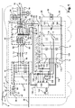
- the figure 5 represents a model of the power part of the charger 100.
- the block R, L corresponds to a resistor and an inductance connected in series. This inductance and this resistance are incorporated in the tertiary windings 84 to 86 of the transformer 48 and have therefore not been represented on the figure 1 .
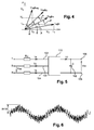
- the figure 6 represents the evolution as a function of time of the current flowing through one of the input terminals 102 to 104 when the device 32 is recharged.
- the maximum peak intensity is equal to 841 A.
- the figure 7 represents the spectrum of the curve represented on the figure 6 . It can be seen that the fundamental frequency of this phase is equal to 50 Hz. The harmonic of the nearest fundamental frequency is in the immediate vicinity of 1050 Hz (the switching frequency). In addition, the amplitude of the fundamental is at least four times greater than the amplitude of the first harmonic. Here, the amplitude of the fundamental is of 454 A.
- the figure 8 represents the evolution as a function of time of the output voltage of the charger 100 when the device 32 is recharged.
- the maximum peak amplitude is 43.7 Vdc, which represents a ripple rate of less than 37%.
- the figure 9 represents the spectrum of the charger output voltage shown on the figure 8 which includes a continuous component.
- the first significant harmonic of 50 Hz is rejected beyond 1050 Hz.
- the amplitude of the DC component not represented on the figure 9 is also greater than at least four times the amplitude of the first harmonic.
- the figure 10 represents the evolution as a function of time of the intensity of the current flowing through one of the terminals 102 to 104.
- the maximum peak intensity is equal to 575 A.
- the figure 11 represents the spectrum of the current represented on the figure 10 .
- the scale used for the figure 11 is the same as the one used for the figure 7 .
- the fundamental is located at 50 Hz.
- the first harmonic is located above 3450 Hz.
- the amplitude of the fundamental is at least ten times greater than the amplitude of the first harmonic.
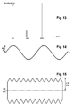
- the figure 12 represents the rectified DC voltage produced by the charger 100 when the device 32 is loaded.
- the largest peak amplitude here is 11.9 Vdc, which represents a ripple rate of less than 10%.
- the figure 13 represents the spectrum of the rectified DC voltage of the figure 12 which comprises a DC component located at 0 Hz and not shown.
- the first significant harmonic of 50 Hz is pushed back to more than 3450 Hz of the fundamental one.
- the amplitude of the DC component is at least five times greater than the amplitude of the first harmonic.
- Figures 14 and 15 were obtained with a frequency of 15150 Hz for the carrier of the pulse width modulation.
- the figure 14 represents the intensity of the current flowing through one of the terminals 102 to 104.
- the maximum peak intensity is 484.2 A.
- the first harmonic is pushed back to more than 15150 Hz of the fundamental frequency.
- the figure 15 represents the outer envelope of the variations of the rectified DC voltage produced by the charger 100 when it loads the device 32.
- the maximum peak amplitude is equal to 2.55 Vdc, which corresponds to a ripple rate of less than 3 %.
- the first harmonic is pushed back to more than 15150 Hz of the fundamental.
- the higher the carrier frequency of the pulse width modulation i.e. the higher the switching frequency, the more the first harmonic is rejected far from the fundamental.
- the value of the transformer dispersion inductance and the capacitance of the capacitor 152 can be reduced, which results in a reduction in the bulk of these components and in particular the filter 150. .
- the charger 100 may be connected to the conductors 14, 15 and 16 via a three-phase transformer independent of the transformer 48.
- the tertiary windings of the transformer 48 may be omitted.
- the control of the battery charger 110 described herein is a vector control.
- a scalar control can be used instead of the vector control from the moment when the switching frequency of the transistors remains at least twenty times greater than the fundamental frequency of the three-phase voltage.
- the railway vehicles comprise at least one second auxiliary converter identical, for example, to the converter 10.
- the auxiliary emergency loads are fed via a low-voltage DC bus connected to the terminals of the device 32 and not via the three-phase auxiliary bus 12.
- the capacitor bank C1, C2, C3 can be broken down into two parts with a portion that is eliminated in order to be able to supply the reactive power during normal operation and to compensate the magnetising current of the transformer in emergency mode.
- the precharge of the capacitor can be performed from the battery (deletion of the preloading device 52,54).
- the switching frequency be greater than at least twenty times the fundamental frequency of the three-phase voltage.
- the size and the mass of the filter 150 are not necessarily diminished but, on the other hand, the advantage of having a single and same reversible rectifier for exchanging electrical energy in both directions between the auxiliary loads and the device 32.
Landscapes
- Engineering & Computer Science (AREA)
- Power Engineering (AREA)
- Transportation (AREA)
- Mechanical Engineering (AREA)
- Life Sciences & Earth Sciences (AREA)
- Sustainable Development (AREA)
- Sustainable Energy (AREA)
- Business, Economics & Management (AREA)
- Emergency Management (AREA)
- Charge And Discharge Circuits For Batteries Or The Like (AREA)
- Stand-By Power Supply Arrangements (AREA)
Abstract
Description
La présente invention concerne un procédé d'alimentation de charges auxiliaires de secours, un convertisseur auxiliaire et un véhicule ferroviaire mettant en oeuvre ce procédé.The present invention relates to a method of supplying auxiliary backup loads, an auxiliary converter and a railway vehicle implementing this method.
Il existe des procédés d'alimentation de charge auxiliaire de secours d'un véhicule ferroviaire à partir d'un dispositif rechargeable de stockage d'énergie électrique embarqué dans le véhicule. Le dispositif de stockage d'énergie est apte à stocker une quantité d'énergie suffisante pour permettre, dans un mode de secours, le fonctionnement des charges auxiliaires de secours pendant plus d'une trentaine de minutes à partir de cette seule source d'énergie, typiquement entre 30 minutes et une heure.There are methods of supplying auxiliary backup power of a railway vehicle from a rechargeable electrical energy storage device embedded in the vehicle. The energy storage device is capable of storing a sufficient quantity of energy to allow, in an emergency mode, the operation of auxiliary auxiliary loads for more than thirty minutes from this single source of energy typically between 30 minutes and one hour.
Les procédés existants comportent un mode normal dans lequel un chargeur de batterie alimente les charges auxiliaires basse tension et recharge le dispositif de stockage d'énergie électrique, ce chargeur étant apte à produire une tension continue permettant de recharger le dispositif de stockage d'énergie électrique à partir d'une tension triphasée.The existing methods include a normal mode in which a battery charger supplies the low voltage auxiliary charges and recharges the electrical energy storage device, this charger being able to produce a DC voltage for recharging the electrical energy storage device. from a three-phase voltage.
L'invention proposée concerne l'amélioration d'un convertisseur auxiliaire:
- pour alimentation continue depuis une catenaire sous tension continue ou depuis un pont monophasé à commutation forcé (PMCF) dans le cas d'une caténaire sous tension alternative,
- de topologie générale DPI (Direct PWM Inverter), avec transformateur basse fréquence en sortie (typiquement 50 Hz ou 60 Hz),
- avec un chargeur de batterie alimenté par le transformateur basse fréquence et éventuellement également à partir d'une prise de quai 400Vac.
- for continuous supply from a DC catenary or from a forced-switching single-phase bridge (PMCF) in the case of an AC-powered overhead line
- of general topology DPI (Direct PWM Inverter), with low frequency transformer output (typically 50 Hz or 60 Hz),
- with a battery charger powered by the low frequency transformer and possibly also from a 400Vac shore power outlet.
La tension triphasée est obtenue à partir de l'énergie électrique continue captée sur une caténaire via un onduleur ou sur un bus intermédiaire en courant continu alimenté par un pont redresseur monophasé à commutation forcée (PMCF) dans le cas d'une caténaire sous tension alternative.The three-phase voltage is obtained from the continuous electrical energy sensed on a catenary via an inverter or on a DC intermediate bus powered by a forced-switching single-phase rectifier bridge (PMCF) in the case of an AC voltage overhead line. .
Le chargeur comporte :
- trois bornes d'entrée raccordées chacune à l'une des phases de la tension triphasée,
- au moins deux bornes de sortie le plus souvent trois dont deux sont raccordées au dispositif de stockage d'énergie électrique, sur lesquelles est délivrée la tension continue redressée.
- three input terminals each connected to one of the phases of the three-phase voltage,
- at least two output terminals, most often three of which two are connected to the electrical energy storage device, on which the rectified DC voltage is delivered.
En effet, généralement, les chargeurs de batterie ont trois bornes de sortie: deux à polarité positive et une à polarité négative, la première borne à polarité positive est raccordée directement à la batterie. La deuxième borne à polarité positive est munie d'une diode antiretour, elle alimente les charges auxiliaires qui doivent être alimentées sous tension continue, permettant ainsi de créer un réseau auxiliaire basse tension alimenté éventuellement par plusieurs batteries et plusieurs chargeurs sur un train, avec la garantie qu'en cas de court-circuit d'une batterie ou d'un chargeur le bus reste alimenté.In fact, generally, the battery chargers have three output terminals: two with positive polarity and one with negative polarity, the first positive polarity terminal is connected directly to the battery. The second positive polarity terminal is provided with a non-return diode, it supplies the auxiliary loads which must be supplied with DC voltage, thus making it possible to create a low voltage auxiliary network possibly fed by several batteries and several chargers on a train, with the guarantee that in the event of a short circuit of a battery or a charger the bus remains energized.
Le chargeur comporte également
- un redresseur triphasé dont chacun des trois bras est raccordé en entrée au réseau triphasé et dont la sortie continue est raccordée aux bornes de sortie du chargeur de batterie, le redresseur étant soit un pont à thyristors, soit un pont mixte à thyristor et diodes,
- une unité de pilotage de la commutation des thyristors pour redresser la tension triphasée.
- a three-phase rectifier, each of the three arms of which is connected as input to the three-phase network and whose DC output is connected to the output terminals of the battery charger, the rectifier being either a thyristor bridge or a mixed thyristor and diode bridge,
- a thyristor switching control unit for rectifying the three-phase voltage.
Les charges auxiliaires d'un véhicule ferroviaire sont toutes les charges électriques embarquées dans un véhicule ferroviaire à l'exception des moteurs de propulsion du véhicule ferroviaire. Ces charges auxiliaires sont de deux types :
- des charges triphasées alternatives alimentées en moyenne tension, et
- des charges alimentées en basse tension.
- three-phase alternating loads supplied with medium voltage, and
- loads supplied with low voltage.
Les charges triphasées alternatives moyenne tension sont alimentées pour des raisons de redondance par plusieurs convertisseurs auxiliaires soit via des réseaux différents (généralement deux), qui peuvent être reliés en cas de panne d'un convertisseur auxiliaire grâce à un contacteur de couplage entre eux soit via un réseau unique, les convertisseurs auxiliaires étant alors synchronisés entre eux. Par moyenne tension, il faut comprendre une tension triphasée comprise entre 350 Vac et 500 Vac. Ces charges auxiliaires moyenne tension sont, par exemple, des climatiseurs, des radiateurs pour chauffer l'intérieur des voitures, des éclairages ou des humidificateurs.The three-phase alternating medium voltage loads are fed for redundancy reasons by several auxiliary converters or via different networks (usually two), which can be connected in case of failure of an auxiliary converter thanks to a coupling contactor between them or via a single network, the auxiliary converters then being synchronized with each other. By medium voltage, it is necessary to understand a three-phase voltage included between 350 Vac and 500 Vac. These auxiliary medium voltage loads are, for example, air conditioners, radiators for heating the interior of cars, lights or humidifiers.
Les charges alimentées en basse tension continue sont alimentées par le réseau basse tension avec la batterie en tampon, les tensions batterie normalisées étant de 24, 48, 72, 96, et 110Vdc. Ces charges auxiliaires basse tension sont par exemple de l'appareillage, des électroniques de contrôle, les services d'information voyageur, toute ou une partie de l'éclairage ...The charges supplied with low DC voltage are fed by the low voltage network with the buffer battery, the normalized battery voltages being 24, 48, 72, 96, and 110Vdc. These low voltage auxiliary charges are, for example, switchgear, control electronics, traveler information services, all or part of the lighting, etc.
Par convertisseur auxiliaire, on désigne l'équipement électrique propre à produire la moyenne tension triphasée et la basse tension continue alimentant les charges auxiliaires à partir de l'énergie électrique captée par l'intermédiaire de la caténaire. Généralement, cet équipement est logé à l'intérieur d'une même enceinte.Auxiliary converter means the electrical equipment suitable for producing the three-phase medium voltage and the low direct voltage supplying the auxiliary charges from the electrical energy sensed via the catenary. Generally, this equipment is housed inside a same enclosure.
On désigne également dans ce texte, par « basse tension » une tension continue dont la valeur est inférieure à 150 Vdc.Also referred to in this text as "low voltage" is a DC voltage whose value is less than 150 Vdc.
Par le terme « caténaire » on désigne, aussi bien des fils aériens suspendus au-dessus des voies de chemin de fer et permettant d'alimenter le véhicule ferroviaire, qu'un troisième rail au sol s'étendant le long des voies de chemin de fer et sur lequel frotte un patin, de manière à alimenter le véhicule ferroviaire en énergie électrique.By the term "catenary" is meant, both overhead wires suspended over railway tracks and used to feed the railway vehicle, a third rail on the ground extending along the road ways of iron and on which rubs a pad, so as to supply the railway vehicle with electrical energy.
La fréquence de commutation d'un élément électronique commandable de commutation de puissance est définie comme étant l'inverse du nombre de commutations de cet élément par unité de temps. Cette fréquence de commutation est, typiquement égale à la fréquence de la porteuse d'une modulation de largeur d'impulsions lorsque les instants de commutation sont déterminés par un tel procédé. L'expression « modulation de largeur d'impulsions » est parfois plus connue sous l'acronyme de PWM (Pulse Width Modulation).The switching frequency of a controllable electronic switching element of power is defined as being the inverse of the number of commutations of this element per unit of time. This switching frequency is typically equal to the carrier frequency of a pulse width modulation when the switching times are determined by such a method. The term "pulse width modulation" is sometimes better known by the acronym PWM (Pulse Width Modulation).
Dans les procédés existants, les interrupteurs commandables sont formés de thyristors et un filtre passe bas est raccordé entre les bornes de sortie du chargeur pour lisser la tension continue redressée. Ce filtre comporte typiquement un condensateur et une inductance en série, ce type de filtre est nécessaire car des créneaux de tension sont appliqués par les thyristors à la sortie du redresseur.In existing methods, the controllable switches are formed of thyristors and a low pass filter is connected between the output terminals of the charger to smooth the rectified DC voltage. This filter typically comprises a capacitor and a series inductor, this type of filter is necessary because voltage pulses are applied by the thyristors at the output of the rectifier.
Actuellement, ce filtre L-C est encombrant et lourd, et la présence d'harmoniques de redressement impose également des contraintes sur le filtre triphasé du réseau moyenne tension.Currently, this L-C filter is cumbersome and heavy, and the presence of rectifier harmonics also imposes constraints on the three-phase filter of the medium voltage network.
Grâce à un redresseur régénératif du type décrit dans l'article
Par ailleurs, certaines charges auxiliaires à alimentation triphasée alternative notamment la ventilation de secours des métros nécessitent l'installation d'onduleurs dédiés raccordables à la batterie, de manière à pouvoir être alimentés en mode de secours, c'est-à-dire en l'absence de tension caténaire, l'onduleur principal alimenté en mode normal par la caténaire n'étant plus alimenté.Moreover, some auxiliary loads with AC three-phase supply, such as the emergency ventilation of metros, require the installation of dedicated inverters connectable to the battery, so that they can be powered in emergency mode, that is to say in the absence of catenary voltage, the main inverter fed in normal mode by the catenary is no longer supplied.
Cela constitue une masse et un encombrement important d'équipements et par conséquent un coût de fabrication plus élevé.This is a mass and a large size of equipment and therefore a higher manufacturing cost.
Le problème technique est de diminuer la masse et l'encombrement des équipements nécessaires en mode normal et en mode de secours, tout en conservant les performances de filtrage des harmoniques obtenues pour les configurations d'équipements actuelles.The technical problem is to reduce the mass and the bulk of the necessary equipment in normal mode and in emergency mode, while maintaining the harmonic filter performance obtained for current equipment configurations.
A cet effet l'invention a pour objet un procédé d'alimentation des charges auxiliaires triphasées dans lequel le procédé comprend les étapes consistant en ce que :
- il est fourni dans chaque bras du redresseur deux éléments électroniques commandables de commutation de puissance propres à être ouverts et fermés de manière commandée et à commuter en mode normal le courant circulant dans le bras où ils sont placés,
- en mode normal, une unité de pilotage commande l'allumage et l'extinction des éléments électroniques à des instants déterminés pour redresser la tension triphasée, la fréquence de commutation des éléments électroniques étant supérieure à au moins vingt fois la fréquence fondamentale de la tension triphasée, et
- en mode de secours, c'est-à-dire en l'absence de tension caténaire, l'onduleur principal n'est plus commandé et le chargeur de batterie est commandé comme un onduleur par l'unité de pilotage,
- l'unité de pilotage commande la commutation des éléments électroniques de l'état passant vers l'état non passant et vice versa à des instants déterminés pour produire une tension triphasée sur le réseau auxiliaire permettant le fonctionnement des charges auxiliaires de secours, cette tension triphasée étant produite à partir de l'énergie stockée dans le dispositif de stockage d'énergie électrique.
- in each arm of the rectifier are provided two controllable electronic power switching elements able to be opened and closed in a controlled manner and to switch in normal mode the current flowing in the arm where they are placed,
- in normal mode, a control unit controls the switching on and off of the electronic elements at determined times to rectify the three-phase voltage, the switching frequency of the electronic elements being greater than at least twenty times the fundamental frequency of the three-phase voltage , and
- in emergency mode, that is to say in the absence of catenary voltage, the main inverter is no longer controlled and the battery charger is controlled as an inverter by the control unit,
- the control unit controls the switching of the electronic elements from the on state to the off state and vice versa at given times to produce a three-phase voltage on the auxiliary network for the operation of the auxiliary auxiliary loads, this three-phase voltage being produced from the energy stored in the electrical energy storage device.
Dans le procédé ci-dessus, le fait d'utiliser des éléments électroniques commandables notamment des transistors permet de déterminer librement non seulement l'instant d'allumage, mais également l'instant d'extinction. Un transistor offre donc plus de possibilités de commandes qu'un thyristor dont seul l'allumage peut être commandé. Cette possibilité additionnelle est ici mise en oeuvre pour hacher le courant à redresser avec une fréquence de commutation beaucoup plus élevée que la fréquence de la tension triphasée. Le hachage haute fréquence permet d'utiliser l'inductance de fuite du transformateur pour effectuer le lissage du courant et donc de se passer d'inductance de sortie le redresseur se transforme ainsi en source de courant. Les harmoniques de courant ainsi crées peuvent être filtrées par un condensateur placé en sortie du chargeur de batterie.In the above method, the fact of using controllable electronic elements including transistors freely determines not only the ignition time, but also the instant of extinction. A transistor thus offers more control possibilities than a thyristor whose only ignition can be controlled. This additional possibility is here implemented to chop the current to be rectified with a switching frequency much higher than the frequency of the three-phase voltage. The high frequency chopping makes it possible to use the leakage inductance of the transformer to effect the smoothing of the current and thus to dispense with output inductance. The rectifier thus transforms into a current source. The current harmonics thus created can be filtered by a capacitor placed at the output of the battery charger.
En outre, du fait que le redresseur est composé de six éléments électroniques commandables de commutation de puissance, il est intrinsèquement réversible, c'est-à-dire qu'il peut être commandé comme un onduleur en l'absence de tension caténaire (mode secours). Il peut alors alimenter certaines charges auxiliaires à alimentation alternative (ventilation de secours) sans avoir recours à un onduleur de secours spécifique et séparé.In addition, because the rectifier is composed of six controllable electronic switching elements, it is intrinsically reversible, that is to say it can be controlled as an inverter in the absence of catenary voltage (mode backup). It can then feed some ancillary loads with AC power (emergency ventilation) without the need for a specific and separate emergency UPS.
Les modes de réalisation de ce procédé peuvent comporter une ou plusieurs des caractéristiques suivantes :
- la fréquence de commutation des éléments électroniques est également au moins vingt fois supérieure à la fréquence fondamentale de la tension triphasée produite ;
- en mode normal, un transformateur triphasé produit une moyenne tension triphasée comprise entre 350 et 500 Vac sur le bus auxiliaire à partir de l'énergie captée sur la caténaire pour alimenter les charges auxiliaires qui sont raccordées à ce bus auxiliaire ;
- la caténaire est à tension continue et en mode normal, un onduleur produit une tension triphasée en entrée du transformateur triphasé à partir de l'énergie captée sur la caténaire,
- la caténaire est à tension alternative et en mode normal un pont redresseur monophasé produit une tension redressée continue en entrée d'un onduleur raccordé en entrée au transformateur triphasé,
- en mode normal, l'unité de pilotage est propre à commander de manière synchrone les interrupteurs commandables des trois bras et de l'onduleur,
- les éléments électroniques commandables de commutation de puissance sont des transistors (de préférence de type IGBT) ou des GTO s (Gate Turn off thyristor),
- en mode normal:
- l'unité de pilotage établit une grandeur représentative de la puissance active à partir de mesures du courant triphasé et de la tension triphasée,
- l'unité de pilotage acquiert une consigne de puissance active qui détermine la valeur de la puissance active transférée par le chargeur entre ses bornes d'entrée et de sortie et aussi le sens de transfert de la puissance active entre ses bornes,
- l'unité de pilotage détermine les instants de commutation des éléments électroniques commandables de commutation de puissance en fonction de la différence entre la consigne de puissance active et la grandeur établie représentative de la puissance active ;
- l'unité de pilotage établit une grandeur représentative de la puissance réactive à partir de mesures du courant triphasé et de la tension triphasée,
- l'unité de pilotage est programmée avec une consigne de puissance réactive qui détermine la valeur de la puissance réactive transférée par le chargeur entre ses bornes d'entrée et de sortie et aussi le sens de transfert de la puissance réactive entre ses bornes,
- l'unité de pilotage détermine les instants de commutation des transistors en fonction de la différence entre la consigne de puissance réactive et la grandeur établie représentative de la puissance réactive ;
- en mode normal, la consigne de puissance réactive est nulle ;
- en mode de secours, l'unité de pilotage régule la tension et la fréquence du réseau à des valeurs prédéterminées inscrites dans une mémoire ;
- avant un basculement du mode normal vers le mode de secours, l'unité de pilotage détermine les instants de commutation des transistors de manière à annuler la différence entre la phase de la tension triphasée mesurée sur le bus auxiliaire et la phase de la tension triphasée entre les bornes d'entrée du chargeur, cette dernière phase étant fonction uniquement des instants de commutation des transistors.
- the switching frequency of the electronic elements is also at least twenty times greater than the fundamental frequency of the three-phase voltage produced;
- in normal mode, a three-phase transformer produces a medium-voltage three-phase between 350 and 500 Vac on the auxiliary bus from the energy captured on the catenary to supply the auxiliary loads which are connected to this auxiliary bus;
- the catenary is at DC voltage and in normal mode, an inverter produces a three-phase voltage at the input of the three-phase transformer from the energy captured on the catenary,
- the catenary is at alternating voltage and in normal mode a single-phase rectifier bridge produces a DC rectified voltage at the input of an inverter connected to the input to the three-phase transformer,
- in normal mode, the control unit is able to synchronously control the controllable switches of the three arms and the inverter,
- the controllable electronic switching elements of power are transistors (preferably IGBT type) or GTOs (gate turn off thyristor),
- in normal mode:
- the control unit establishes a magnitude representative of the active power from measurements of the three-phase current and the three-phase voltage,
- the control unit acquires an active power setpoint which determines the value of the active power transferred by the charger between its input and output terminals and also the direction of transfer of the active power between its terminals,
- the control unit determines the switching times of the controllable power switching electronic elements as a function of the difference between the active power setpoint and the established magnitude representative of the active power;
- the control unit establishes a magnitude representative of the reactive power from measurements of the three-phase current and the three-phase voltage,
- the control unit is programmed with a reactive power setpoint which determines the value of the reactive power transferred by the charger between its input and output terminals and also the direction of transfer of the reactive power between its terminals,
- the control unit determines the switching times of the transistors as a function of the difference between the reactive power setpoint and the determined magnitude representative of the reactive power;
- in normal mode, the reactive power setpoint is zero;
- in emergency mode, the control unit regulates the voltage and frequency of the network to predetermined values stored in a memory;
- before switching from the normal mode to the emergency mode, the control unit determines the switching times of the transistors so as to cancel the difference between the phase of the three-phase voltage measured on the auxiliary bus and the phase of the three-phase voltage between the input terminals of the charger, this last phase being a function only of the switching times of the transistors.
Ces modes de réalisation du procédé d'alimentation présentent en outre les avantages suivants :
- la commande de la commutation des transistors pour produire une tension triphasée permet d'utiliser les mêmes transistors pour charger le dispositif de stockage d'énergie et alimenter les charges auxiliaires de secours, ce qui décroît le coût et l'encombrement des équipements nécessaires pour alimenter les charges auxiliaires de secours,
- utiliser un transformateur triphasé pour produire la moyenne tension qui alimente le bus auxiliaire permet d'utiliser le même bus auxiliaire pour alimenter les charges auxiliaires de secours aussi bien dans le mode normal que dans le mode de secours,
- déterminer les instants de commutation des transistors en fonction de la différence entre la consigne de puissance réactive et la grandeur mesurée représentative de la puissance réactive permet de régler la puissance réactive qui transite des bornes d'entrée vers les bornes de sortie du chargeur,
- imposer une puissance réactive nulle en mode normal permet de limiter les pertes d'énergie,
- déterminer les instants de commutation des transistors en fonction de la différence entre la phase de la tension triphasée sur le bus auxiliaire et la phase de la tension entre les bornes d'entrée du chargeur permet d'assurer une continuité de la phase de la tension triphasée sur le bus auxiliaire lorsque l'on passe du mode normal au mode de secours.
- le mode secours présentant la particularité de générer de la tension à l'entrée de l'onduleur principal, par redressement passif de la tension triphasée au primaire du transformateur, ce phénomène peut être exploité pour
- o Précharger le condensateur du filtre d'entrée de l'onduleur principal à partir de la batterie, en faisant fonctionner le charger de batterie en onduleur (suppression du contacteur et de la résistance de précharge),
- o recréer de la tension caténaire, ce qui pourrait être utilisé comme source d'énergie pour faire avancer le train en l'absence de caténaire,
- controlling the switching of the transistors to produce a three-phase voltage makes it possible to use the same transistors for charging the energy storage device and supplying the auxiliary emergency loads, which decreases the cost and the bulk of the equipment necessary to supply auxiliary auxiliary loads,
- using a three-phase transformer to produce the medium voltage supplying the auxiliary bus makes it possible to use the same auxiliary bus to supply the auxiliary emergency loads in both the normal mode and the emergency mode,
- determining the switching times of the transistors as a function of the difference between the reactive power setpoint and the measured quantity representative of the reactive power makes it possible to adjust the reactive power which passes from the input terminals to the output terminals of the charger,
- to impose a reactive power of zero in normal mode makes it possible to limit the losses of energy,
- determining the switching times of the transistors as a function of the difference between the phase of the three-phase voltage on the auxiliary bus and the phase of the voltage between the input terminals of the charger makes it possible to ensure continuity of the phase of the three-phase voltage on the auxiliary bus when switching from normal mode to emergency mode.
- the emergency mode having the particularity of generating voltage at the input of the main inverter, by passive rectification of the three-phase voltage at the primary of the transformer, this phenomenon can be exploited to
- o Preload the input filter capacitor of the main inverter from the battery, by running the inverter battery charger (removing the contactor and the precharge resistor),
- o recreate catenary voltage, which could be used as a source of energy to move the train forward without a catenary,
L'invention a également pour objet un convertisseur auxiliaire, ce convertisseur comportant :
- un onduleur triphasé propre à générer une tension triphasée à partir de l'énergie électrique captée sur une caténaire,
- un transformateur triphasé à trois ensembles primaire, secondaire, et tertiaire d'enroulements, connecté sur la sortie triphasée de l'onduleur par le primaire du transformateur, l'ensemble onduleur / transformateur étant apte, en mode normal, à transformer la tension caténaire en moyenne tension triphasée comprise entre 350 Vac et 500 Vac délivrable au secondaire du transformateur sur un réseau auxiliaire d'alimentation de charges auxiliaires,
- un chargeur, connecté au tertiaire du transformateur et apte, en mode normal, à générer une tension continue redressée à partir de la tension triphasée produite par l'onduleur triphasé, ce chargeur comportant :
- trois bornes d'entrée raccordées chacune à un enroulement du tertiaire du transformateur,
- deux bornes de sortie raccordées au dispositif de stockage d'énergie électrique, sur lesquelles est délivrée la tension continue redressée,
- trois bras raccordés en parallèle entre les deux bornes de sortie, chaque bras comportant deux interrupteurs commandables raccordés en série par l'intermédiaire d'un point milieu, chaque point milieu étant raccordé à une borne d'entrée respective,
- une unité de pilotage de la commutation des interrupteurs pour redresser la tension triphasée,
- les interrupteurs comportent chacun au moins un élément électronique commandable de commutation de puissance propre à être ouvert, état non passant, et fermé, état passant, de manière commandée et à commuter le courant circulant dans le bras où il est placé, et
- l'unité de pilotage est propre à commander la commutation des éléments électroniques du chargeur de l'état passant vers l'état non passant et de l'état non passant vers l'état passant à des instants déterminés pour redresser la tension triphasée, la fréquence de commutation des éléments électroniques étant supérieure à au moins vingt fois la fréquence fondamentale de la tension triphasée.
- a three-phase inverter capable of generating a three-phase voltage from the electrical energy captured on a catenary,
- a three-phase transformer with three sets primary, secondary, and tertiary windings, connected to the three-phase output of the inverter by the primary of the transformer, the inverter / transformer assembly being able, in normal mode, to transform the catenary voltage into three-phase medium voltage of between 350 Vac and 500 Vac which can be delivered to the transformer secondary on an auxiliary auxiliary power supply network,
- a charger, connected to the tertiary of the transformer and adapted, in normal mode, to generate a DC voltage rectified from the three-phase voltage produced by the three-phase inverter, this charger comprising:
- three input terminals each connected to a tertiary winding of the transformer,
- two output terminals connected to the electrical energy storage device, on which the rectified DC voltage is delivered,
- three arms connected in parallel between the two output terminals, each arm having two controllable switches connected in series via a midpoint, each midpoint being connected to a respective input terminal,
- a switching control unit of the switches for rectifying the three-phase voltage,
- the switches each comprise at least one controllable electronic switching element capable of being turned on, off state, and closed, on state, in a controlled manner and to switch the current flowing in the arm where it is placed, and
- the control unit is able to control the switching of the electronic elements of the charger from the on state to the off state and from the non-on state to the on state at given times to rectify the three-phase voltage, the switching frequency of the electronic elements being greater than at least twenty times the fundamental frequency of the three-phase voltage.
Les modes de réalisation de ce convertisseur peuvent comporter une ou plusieurs des caractéristiques suivantes :
- l'unité de pilotage est apte, en mode de secours, à commander la commutation des éléments électroniques de l'état passant vers l'état non passant et vice versa à des instants déterminés pour produire une tension triphasée entre les bornes d'entrée à partir de la tension continue présente entre ses bornes de sortie, la fréquence de commutation des transistors étant au moins vingt fois supérieure à la fréquence de la tension triphasée produite ;
- le chargeur est électriquement isolé de l'onduleur triphasé par l'intermédiaire du transformateur triphasé.
- the control unit is able, in emergency mode, to control the switching of the electronic elements from the on state to the off state and vice versa at times determined to produce a three-phase voltage between the input terminals to from the DC voltage present between its output terminals, the switching frequency of the transistors being at least twenty times greater than the frequency of the three-phase voltage produced;
- the charger is electrically isolated from the three-phase inverter via the three-phase transformer.
L'invention a également pour objet un véhicule ferroviaire comportant :
- un réseau auxiliaire triphasé,
- au moins une charge auxiliaire de secours dont l'alimentation doit être maintenue pendant plus d'une trentaine de minutes dans un mode de secours, cette charge étant raccordée au réseau auxiliaire,
- un dispositif rechargeable de stockage d'énergie électrique raccordable à chaque charge auxiliaire de secours, ce dispositif étant propre à stocker une quantité d'énergie suffisante pour permettre, en mode de secours, le fonctionnement de toutes les charges auxiliaires de secours pendant plus de dix minutes à partir de cette seule source d'énergie,
- au moins le convertisseur auxiliaire ci-dessus pour alimenter le réseau auxiliaire.
- a three-phase auxiliary network,
- at least one auxiliary backup load whose power supply must be maintained for more than thirty minutes in an emergency mode, this load being connected to the auxiliary network,
- a rechargeable electrical energy storage device connectable to each auxiliary backup load, this device being able to store a sufficient quantity of energy to allow, in emergency mode, the operation of all the auxiliary auxiliary loads for more than ten minutes from this single source of energy,
- at least the auxiliary converter above for supplying the auxiliary network.
L'invention sera mieux comprise à la lecture de la description qui va suivre, donnée uniquement à titre d'exemple non limitatif et faite en se référant aux dessins sur lesquels :
- la
figure 1 est une illustration schématique d'un véhicule ferroviaire équipé d'un chargeur de batterie, - la
figure 2 est une illustration schématique d'une unité de pilotage du chargeur de batterie de lafigure 1 , - la
figure 3 est un organigramme d'un procédé d'alimentation de charges auxiliaires de secours dans le véhicule de lafigure 1 , - la
figure 4 est un graphe représentant un certain nombre de vecteurs utilisés dans le procédé de lafigure 3 , - la
figure 5 est une illustration schématique d'un modèle du chargeur de batterie du véhicule ferroviaire de lafigure 1 utilisé pour simuler le procédé de lafigure 3 , - les
figures 6 ,10 et14 sont des chronogrammes illustrant l'allure de la forme d'onde d'une phase du courant triphasée produite par le chargeur de batterie, - les
figures 7 et11 sont des graphes représentant le spectre du courant représenté, respectivement, sur lesfigures 6 et10 , - les
figures 8 ,12 et15 sont des chronogrammes représentant l'évolution de la tension continue redressée par le chargeur de batterie pour différentes fréquences de commutation, et - les
figures 9 et13 sont des graphes illustrant le spectre des tensions illustrées, respectivement, sur lesfigures 8 et 12 .
- the
figure 1 is a schematic illustration of a railway vehicle equipped with a battery charger, - the
figure 2 is a schematic illustration of a control unit of the battery charger of thefigure 1 , - the
figure 3 is a flowchart of a method of supplying auxiliary emergency loads in the vehicle of thefigure 1 , - the
figure 4 is a graph representing a number of vectors used in the process of thefigure 3 , - the
figure 5 is a schematic illustration of a model of the rail vehicle battery charger of thefigure 1 used to simulate the process of thefigure 3 , - the
figures 6 ,10 and14 are timing diagrams illustrating the shape of the waveform of a phase of the three-phase current produced by the battery charger, - the
figures 7 and11 are graphs representing the spectrum of the current represented, respectively, on thefigures 6 and10 , - the
figures 8 ,12 and15 are timing diagrams showing the evolution of the DC voltage rectified by the battery charger for different switching frequencies, and - the
figures 9 and13 are graphs illustrating the spectrum of the voltages illustrated, respectively, on thefigures 8 and12 .
Dans ces figures, les mêmes références sont utilisées pour désigner les mêmes éléments.In these figures, the same references are used to designate the same elements.
Dans la suite de cette description, les caractéristiques et fonctions bien connues de l'homme du métier ne sont pas décrites en détail.In the remainder of this description, the features and functions well known to those skilled in the art are not described in detail.
La
Le véhicule 2 est, par exemple, un métro équipé d'une ventilation de secours, un train ou un tramway.The
Le véhicule 2 comprend un convertisseur auxiliaire 10 propre à alimenter en moyenne tension triphasée un réseau auxiliaire 12. La tension triphasée sur le bus 12 est égale à 400 Vac.The
Le réseau auxiliaire 12 comprend trois conducteurs de phases 14 à 16 et un conducteur de neutre 18.The
Typiquement, le réseau auxiliaire 12 s'étend dans plusieurs voitures du véhicule 2.Typically, the
En variante, le véhicule 2 comprend au moins deux convertisseurs auxiliaires et généralement au moins deux bus à 400 Vac.In a variant, the
L'ensemble des charges auxiliaires embarquées dans ce véhicule 2 sont raccordées au bus 12. Les charges basse tension continue ici ne sont pas représentées.The set of auxiliary charges embedded in this
Les charges auxiliaires sont réparties en deux groupes, un groupe de charges auxiliaires simples et un groupe de charges auxiliaires de secours. Les charges auxiliaires simples sont celles qui doivent être alimentées en mode normal et qui ne doivent pas être alimentées en mode de secours. Le mode normal est ici défini comme étant le mode de fonctionnement dans lequel les charges auxiliaires simples sont alimentées à partir de l'énergie captée par l'intermédiaire du pantographe 4. Les charges auxiliaires de secours sont également alimentées par l'intermédiaire du bus 12 à partir de l'énergie captée par l'intermédiaire du pantographe 4 en mode normal.Auxiliary loads are divided into two groups, a group of simple auxiliary loads and a group of auxiliary backup loads. Simple auxiliary loads are those that must be energized in normal mode and must not be energized in emergency mode. The normal mode is here defined as the operating mode in which the simple auxiliary charges are fed from the energy collected via the pantograph 4. The auxiliary auxiliary loads are also powered via the
On définit le mode de secours comme étant le mode de fonctionnement dans lequel seules les charges auxiliaires de secours sont alimentées. Dans le mode de secours, ces charges sont uniquement alimentées à partir d'un dispositif de stockage d'énergie électrique embarqué dans le véhicule 2.The backup mode is defined as the operating mode in which only the auxiliary backup loads are energized. In the emergency mode, these charges are only powered from an electrical energy storage device embedded in the
Typiquement, le mode de secours correspond à un mode de fonctionnement du véhicule 2 suite à une interruption de l'alimentation du véhicule 2 à partir de la caténaire 6. Une telle interruption de l'alimentation peut être d'origine accidentelle ou être provoquée.Typically, the emergency mode corresponds to a mode of operation of the
Pour simplifier la
La charge 20 est, par exemple, la climatisation d'une voiture. La charge 20 est raccordée au réseau auxiliaire 12 par l'intermédiaire d'un contacteur commandable 24. Le contacteur 24 est apte à isoler électriquement la charge 20 du bus 12 en mode de secours.The
La charge 22 est raccordée, sans passer par l'intermédiaire de contacteurs, au réseau 12 de sorte qu'elle est alimentée aussi bien en mode normal qu'en mode de secours. La charge 22 est, par exemple, un ventilateur destiné à faire circuler de l'air dans l'une des voitures du véhicule 2 alimentée en moyenne tension.The
Le convertisseur 10 est ici également apte à alimenter en basse tension un bus continu formé de deux conducteurs 28 et 30 isolés électriquement l'un de l'autre. Ici, la basse tension est typiquement égale à 110 Vdc.The
Un dispositif rechargeable 32 de stockage d'énergie électrique est électriquement raccordé entre les conducteurs 28 et 30. Le dispositif rechargeable 32 de stockage d'énergie comprend deux bornes de sortie.A rechargeable electric
Le dispositif 32 est apte à stocker suffisamment d'énergie pour permettre d'alimenter à lui tout seul les charges auxiliaires de secours pendant plus d'une trentaine de minutes. Par exemple, ici, le dispositif 32 est une batterie.The
Le convertisseur 10 est raccordé par l'intermédiaire de conducteurs 36 et 38 isolés électriquement l'un de l'autre.The
Le convertisseur 10 comprend, logé dans une seule et même enceinte métallique, raccordés les uns après les autres et dans l'ordre qui suit, les éléments suivants :
- un circuit 40 d'isolation et de précharge,
un filtre 42,un onduleur 44,- un filtre de sortie sinusoïdal constitué d'un ensemble de trois inductances triphasées L1, L2, L3 et, d'un ensemble de condensateurs C1,C2,C3
un transformateur 48.
- a circuit 40 for isolation and precharging,
- a
filter 42, - an
inverter 44, - a sinusoidal output filter consisting of a set of three three-phase inductors L1, L2, L3 and a set of capacitors C1, C2, C3
- a
transformer 48.
Le circuit 40 comprend un interrupteur ou contacteur 50 raccordé en série avec le conducteur 36 de manière à pouvoir isoler le convertisseur lorsque l'interrupteur 50 est ouvert et, en alternance, à raccorder le convertisseur à son alimentation lorsque l'interrupteur 50 est fermé.The circuit 40 comprises a switch or
En variante dans le cas d'une caténaire alternative, le convertisseur 10 est raccordé par l'intermédiaire des conducteurs 36 et 38 à un pont monophasé à commutation forcée (PMCF) alimenté par la caténaire via un transformateur.Alternatively in the case of an alternative catenary, the
Le circuit 40 comprend également, raccordé en parallèle à l'interrupteur 50, un interrupteur commandable ou contacteur 52 raccordé en série avec une résistance 54 de précharge. Les circuits de précharge sont connus et le circuit 40 ne sera donc pas décrit ici plus en détail.The circuit 40 also comprises, connected in parallel with the
Le filtre 42 est un filtre LC comportant une inductance L raccordée en série sur le conducteur 36 et un condensateur Cf raccordé entre le conducteur 36 et le conducteur 38.The
L'onduleur 44 est apte à transformer la tension continue filtrée par le filtre 42 en une tension triphasée de fréquence fT. Typiquement, la fréquence fT est comprise entre 45 Hz et 65 Hz. Ici, la fréquence fT est égale à 50 Hz. Chacune des phases de la tension triphasée produite est délivrée par une borne respective 58 à 60.The
Le filtre de sortie sinusoïdal permet de filtrer la tension triphasée produite par l'onduleur 44 sur les bornes 58 à 60. Par exemple, le filtre de sortie sinusoïdal est formé de trois inductances L1, L2 et L3 raccordées par une extrémité, respectivement, aux bornes 58 à 60 et par l'autre extrémité à des bornes respectives 62 à 64 de sortie du filtre 46. En pratique, les inductances L1, L2, L3 sont intégrées sous forme d'inductances de fuite du transformateur.The sinusoidal output filter makes it possible to filter the three-phase voltage produced by the
Les bornes 62, 63 et 64 sont raccordées à une extrémité respective de trois enroulements primaires 70 à 72 du transformateur 48. Les enroulements primaires 70 à 72 sont raccordés en triangle et forment un ensemble d'enroulements primaire.The
Ces enroulements primaires 70 à 72 sont raccordés par couplage électromagnétique à trois enroulements secondaires 74 à 76 formant un ensemble d'enroulements secondaire raccordés en étoile. Les extrémités des enroulements 74 à 76 qui ne sont pas raccordées au point milieu de l'étoile sont raccordées, respectivement, aux bornes 78 et 80 de sortie de la moyenne tension triphasée. Le point milieu du raccordement en étoile des enroulements secondaires est raccordé à une borne de sortie 82.These
Les condensateurs C1, C2 et C3 sont raccordés respectivement entre les bornes 78 et 79, 79 et 80, et 78 et 80.Capacitors C 1 , C 2 and C 3 are respectively connected between
Le rapport du nombre de spires entre les enroulements primaires et secondaires est choisi de manière à délivrer une moyenne tension triphasée sur les bornes 78 à 80. Les bornes 78 à 80 et la borne 82 sont, respectivement, raccordées aux conducteurs 14 à 16 et 18. Le transformateur 48 permet donc d'alimenter en moyenne tension le réseau auxiliaire 12.The ratio of the number of turns between the primary and secondary windings is chosen so as to deliver a three-phase average voltage across
Le transformateur 48 comprend également trois enroulements tertiaires 84 à 86 couplés électromagnétiquement aux enroulements primaires 70 à 72 et aux enroulements secondaires 74 à 76 et formant un ensemble d'enroulements tertiaire. Une extrémité des enroulements tertiaires est raccordée à un point milieu de manière à former un raccordement en étoile. L'autre extrémité de ces enroulements tertiaires est raccordée à des bornes de sortie, respectivement, 88 à 90.
Le convertisseur 2 comprend également un chargeur 100 de batterie. Ce chargeur 100 comprend trois bornes d'entrée 102 à 104 raccordées, respectivement, aux bornes 88 à 90.The
Le chargeur 100 comprend également deux bornes 106 et 108, respectivement associées aux bornes du dispositif de recharge 32 électriquement raccordées aux conducteurs 28 et 30.The
En variante, des charges auxiliaires non représentées peuvent être également raccordées sur la sortie du chargeur de batterie et en parallèle de celle-ci.Alternatively, auxiliary loads not shown can also be connected to the output of the battery charger and in parallel thereof.
Le courant de charge de la batterie 32 est également mesuré au moyen d'un capteur de courant.The charging current of the
Ici, le chargeur 100 est réversible, c'est-à-dire qu'il est capable de transférer de l'énergie électrique des bornes d'entrée 102 à 104 vers les bornes de sortie 106 et 108 pour recharger le dispositif 32 mais également dans le sens inverse de manière à pouvoir alimenter les charges auxiliaires de secours à partir du dispositif 32.Here, the
Le chargeur 100 comprend à cet effet, un redresseur réversible 110 comportant trois bras 112 à 114 raccordés en parallèle entre les bornes 106 et 108. Chaque bras comprend deux interrupteurs commandables IH et IB raccordés en série par l'intermédiaire d'un point milieu. Les points milieux des branches 112 à 114 portent, respectivement, les références 116 à 118. Les points milieux 116 à 118 sont, respectivement, raccordés aux bornes 102 à 104.The
Les interrupteurs IH et IB sont des interrupteurs bidirectionnels en courant lorsqu'ils sont fermés et unidirectionnels en courant lorsqu'ils sont ouverts.The switches I H and I B are bidirectional current switches when they are closed and unidirectional current when open.
Chaque interrupteur IB comprend :
- un transistor de puissance 120 dont le collecteur est électriquement raccordé à la borne 106 et l'émetteur au point milieu, et
une diode 122 raccordée en parallèle entre le collecteur et l'émetteur dont la cathode est raccordée à la borne 106 et l'anode au même point milieu.
- a
power transistor 120 whose collector is electrically connected toterminal 106 and the emitter at the midpoint, and - a
diode 122 connected in parallel between the collector and the emitter whose cathode is connected to the terminal 106 and the anode at the same midpoint.
Chaque transistor IH comporte :
- un transistor de puissance 124 dont le collecteur est raccordé au point milieu et dont l'émetteur est raccordé à la borne 108, et
une diode 126 raccordée en parallèle entre le collecteur et l'émetteur dutransistor 124, la cathode de ladiode 126 étant raccordée au même point milieu tandis que l'anode est raccordée à la borne 108.
- a
power transistor 124 whose collector is connected to the midpoint and whose emitter is connected to the terminal 108, and - a
diode 126 connected in parallel between the collector and the emitter of thetransistor 124, the cathode of thediode 126 being connected to the same midpoint while the anode is connected to the terminal 108.
Pour simplifier la
Par transistor de puissance, on désigne des transistors capables de commuter des courants de plus de 50A. Par exemple, les transistors 120 et 124 sont des transistors IGBT (Insulated Gate Bipolar Transistor).By power transistor is meant transistors capable of switching currents of more than 50A. For example,
Chacun de ces transistors 120, 124 est apte à commuter d'un état non passant à un état passant et vice versa, en réponse à une commande reçue sur sa grille.Each of these
A cet effet, les grilles de chacun de ces transistors sont raccordées à une unité de pilotage 130 du redresseur 110 par l'intermédiaire de liaisons électriques schématisées par une double flèche 132.For this purpose, the gates of each of these transistors are connected to a
L'unité de pilotage 130 ou unité centrale est apte à commander le redresseur 110 ainsi que de manière synchrone l'onduleur 44. L'unité de pilotage 130 permet que le redresseur 110 fonctionne en tant que redresseur en mode normal et, en alternance, fonctionne en tant qu'onduleur en mode de secours. A cet effet, l'unité centrale 130 est raccordée à des capteurs de courant 134 à 136 propres à mesurer l'intensité des courants IR, IS, IT circulant, respectivement, par l'intermédiaire des bornes 104 à 102. L'unité 130 est également raccordée à deux capteurs 138, 140, respectivement, des tensions VRT et VRS. Les tensions VRT et VRS sont les tensions, respectivement, entre les bornes 104 et 102 et 104 et 103.The
L'unité 130 est décrite plus en détail en regard de la
L'unité 130 est raccordée à une mémoire 142 contenant les valeurs, en mode normal , pour des consignes Idcsg de puissance active et Iqcsg de puissance réactive. En mode normal, la valeur de la consigne Idcsg est négative. Par exemple, il en est aussi de même pour la valeur de la consigne Iqcsg.The
En mode de secours, il n'y a pas de régulation de puissance active et réactive. En mode secours, l'unité 130 régule la tension et la fréquence du bus 12 à des valeurs prédéterminées inscrites dans la mémoire 142 (par exemple : 250V et 35 Hz). Le rôle de ces consignes apparaîtra plus clairement à la lecture de la suite de cette description.In emergency mode, there is no active and reactive power control. In emergency mode, the
Le chargeur 100 comprend également un condensateur 150 raccordé entre les bornes 106 et 108.. La capacité de ce condensateur 152 est inférieure à 50 mF. Plus précisément, la capacité de ce condensateur 150 est choisie pour que l'ondulation de tension à ses bornes soit de l'ordre de 1%.The
La
On rappelle ici que la puissance active PA est définie par la relation suivante : ![]()
- I est la valeur efficace du courant triphasé,
- U est la valeur efficace de la tension triphasée, et
- ϕ est la valeur du déphasage entre le courant et la tension triphasée.
- I is the rms value of the three-phase current,
- U is the rms value of the three-phase voltage, and
- φ is the phase shift value between the current and the three-phase voltage.
De façon similaire, on définit la puissance réactive PR par la relation suivante : ![]()
![]()
Les courants actif Id et réactif Iq sont, respectivement, égaux à Icosϕ lsin ϕ.The active currents I d and reactive I q are, respectively, equal to Icosφ lsin φ .
Dans le véhicule 2, la valeur efficace U est sensiblement constante, de sorte que les intensités des courants Id et Iq peuvent être considérées comme étant représentatives à elles seules, respectivement, de la puissance active et de la puissance réactive.In the
Le démodulateur 160 envoie les valeurs des courants Id et Iq à une entrée négative, respectivement, de soustracteurs 162 et 164. Une entrée positive du soustracteur 162 est conçue pour recevoir la valeur de la consigne Idcsg. Une sortie du soustracteur 162 est raccordée à un régulateur 166 pour transmette à ce dernier la différence entre la consigne Idcsg et l'intensité mesurée du courant Id. Le régulateur 166 est apte à calculer à partir de cette différence l'abscisse Vd d'un vecteur Uαβcsg, de tension à générer.The
L'entrée positive du soustracteur 164 est conçu pour recevoir la valeur de la consigne Iqcsg enregistrée dans la mémoire 142. Une sortie du soustracteur 164 délivre à un régulateur 168 la différence entre la valeur de la consigne Iqcsg et l'intensité mesurée du courant Iq. A partir de cette différence, le régulateur 168 est apte à calculer l'ordonnée Vq du vecteur Uαβcsg, de tension à générer.The positive input of the
Le démodulateur 160 est également apte à délivrer un angle ρ correspondant à l'angle entre un vecteur Uαβm et l'axe α d'un repère αβ.The
L'unité 130 comprend un bloc 170 de conversion propre à calculer le module M et l'angle α du vecteur Uαβcsg, à partir des abscisses et ordonnées Vd et Vq.The
Un soustracteur 172 permet de calculer la différence ε entre l'angle ρ et un angle γ délivrée par un modulateur 174 de largeur d'impulsions.A
Le soustracteur 172 est apte à délivrer à une boucle 176 à verrouillage de phases (plus connue sous l'acronyme de PLL (Phase Locked Loop)) la différence ε à laquelle a été ajoutée la valeur de l'angle α. A partir de la somme de l'angle α et de la différence ε, la boucle 176 est capable de générer une consigne fs de fréquence.The
Le modulateur 174 est apte à partir du module M et de la fréquence fs à déterminer les instants auxquels doivent être commutés les différents transistors et à commander la commutation de ces transistors aux instants déterminés. A cet effet, par exemple, le modulateur 174 utilise les intersections d'une porteuse avec une modulante. La fréquence de la porteuse fixe la fréquence de commutation des transistors.The
Le fonctionnement du véhicule 2 va maintenant être décrit plus en détail en regard du procédé de la
Initialement, on suppose que le véhicule 2 fonctionne en mode normal lors d'une phase 180. Lors de cette phase 180, le véhicule 2 est alimenté par l'intermédiaire du pantographe 4 et de la caténaire 6. L'interrupteur 50 est dans l'état passant tandis que l'interrupteur 52 servant uniquement pour précharger le filtre d'entrée, une fois le filtre chargé, est commandé ouvert. Initialement, lors d'une étape 182, les charges auxiliaires simples sont électriquement raccordées au bus 12 de manière à pouvoir être alimentées à partir de celui-ci.Initially, it is assumed that the
Ensuite, lors d'une étape 184, l'onduleur 44 produit sur les bornes 58 à 60 une tension triphasée à partir de la tension continue présente entre les conducteurs 36 et 38.Then, during a
Lors d'une étape 186, le transformateur 48 transforme la tension triphasée produite par l'onduleur 44 en une moyenne tension triphasée délivrée sur le bus auxiliaire 12.In a
Lors d'une étape 188, les différentes charges auxiliaires raccordées au bus 12 sont donc alimentées à partir de l'énergie captée par le pantographe 4. Ainsi, les charges 20 et 22 sont alimentées et fonctionnent.During a
En parallèle, lors d'une étape 190, le transformateur 48 délivre également de la tension triphasée sur les bornes d'entrée 102 à 104 du chargeur 100.In parallel, during a
Lors d'une étape 192, à partir de la tension triphasée présente sur des bornes d'entrée 102 à 104, le chargeur 100 recharge le dispositif 32. A cet effet, le chargeur 100 redresse la tension triphasée présente sur les bornes 102 à 104 afin de produire une tension continue redressée entre des bornes 106 et 108, ce qui permet de recharger le dispositif 32.In a
Plus précisément, lors d'une opération 194, les capteurs 134 à 136, 138 et 140 mesurent les tensions VRS, VRT et les intensités des courants IR, IS et IT.More precisely, during an
Ensuite, lors d'une opération 196, les valeurs des consignes Idcsg et Iqcsg correspondant au mode normal de fonctionnement sont calculées par le régulateur 130 de manière à respecter une loi de charge de la batterie. Ces valeurs sont négatives, ce qui correspond à un transfert d'énergie par l'intermédiaire du redresseur réversible 110 allant des bornes d'entrée 102 à 104 vers les bornes de sortie 106 et 108. Ici, la consigne Iqcsg est nulle pour ne pas consommer de la puissance réactive.Then, during an
Lors d'une opération 198, le démodulateur 160 détermine à partir des mesures réalisées lors de l'étape 194, les coordonnées Va et Vb d'un vecteur Uαβm de tension dans le repère αβ. A cet effet, la transformée de Concordia est utilisée. Les coordonnées Va et Vb sont ici déterminées à partir des relations suivantes : 
Ce vecteur Uαβm est représenté dans le repère αβ de la
Sur la 
Par exemple, la valeur de l"angle ρ est établie à partir des coordonnées Va et Vb.For example, the value of the angle ρ is established from the coordinates V a and V b .
Ensuite, toujours lors de l'opération 198, le démodulateur 160 établit le courant actif Id mesuré et le courant réactif Iq mesuré à l'aide des relations suivantes : 
Ensuite, lors d'une opération 200, les soustracteurs 162 et 164 calculent les différences ΔId et ΔIq à l'aide des relations suivantes : ![]()
![]()
![]()
![]()
Ensuite, les coordonnées Vd et Vq du vecteur Uαβcsg de consigne de tension permettant d'annuler les différences ΔId, et ΔIq sont calculées. A cet effet, lors d'une opération 202, le régulateur 166 calcule à partir de la différence ΔId la coordonnée Vd du vecteur Uαβcsg. Le régulateur 166 est, par exemple, un régulateur PI (Proportionnel Integral) de manière à stabiliser la régulation de la puissance active. Par exemple, la valeur de la coordonnée Vd est calculée à l'aide de la relation suivante : ![]()
- Kpd et Kid sont les constantes proportionnelle et intégrale du régulateur PI.
- K pd and K id are the proportional and integral constants of the PI controller.
De façon similaire, lors d'une opération 204, le régulateur 168 calcule la valeur de la coordonnée Vq à partir de la différence ΔIq. Lors de l'opération 204, la coordonnée Vq est, par exemple, calculée à l'aide de la relation suivante : ![]()
![]()
Les constantes Kpq et Kiq de la relation (9) n'ont pas nécessairement les mêmes valeurs que celles de la relation (8), Kpd et Kid.The constants K pq and K iq of the relation (9) do not necessarily have the same values as those of the relation (8), K pd and K id .
Lors d'une opération 206, le module 170 calcule l'angle α et le module M du vecteur Uαβcsg, dans le repère αβ à partir des coordonnées Vd et Vq.During an
Le module M est transmis directement au modulateur 174 tandis que l'angle α est transmis au soustracteur 172.The module M is transmitted directly to the
Lors d'une opération 208, le soustracteur 172 calcule la différence ε à l'aide de la relation suivante : ![]()
![]()
L'angle γ est une donnée numérique produite par le modulateur 174.The angle γ is a digital datum produced by the
ε représente la différence entre la phase mesurée de la tension triphasée et la phase de la tension triphasée produite ou absorbée par le redresseurr 110 au même instant.ε represents the difference between the measured phase of the three-phase voltage and the phase of the three-phase voltage produced or absorbed by the
Pour que le redresseur 110 soit synchronisé sur la tension triphasée mesurée, cette différence ε doit être nulle.For the
Le soustracteur 172 additionne également à cette différence ε la valeur de l'angle α délivrée par le module 170. Le résultat de cette addition est transmis à la boucle 176 qui calcule, lors d'une opération 209, la fréquence fs qui permet en même temps d'annuler la différence ε et d'atteindre les consignes Idcsg et Iqcsg de puissance actives et réactives imposées. Par exemple, la boucle 176 calcule la fréquence fs à l'aide de la relation suivante : 
- ekPLL=α+ε,
- kpPLL et kiPLL sont les constantes proportionnelle et intégrale de la régulation PI de la boucle 176.
- e kPLL = α + ε,
- k pPLL and k iPLL are the proportional and integral constants of PI regulation of
loop 176.
Ensuite, lors d'une opération 210, le modulateur 174 détermine les instants de commutation des transistors 120 et 124 de manière à produire une tension triphasée de fréquence fs et dont la valeur efficace est égale au module M. Le modulateur 174 commande également les commutations des transistors 120 et 124 aux instants déterminés.Then, during an
Les opérations 194 et 210 sont réitérées en permanence de sorte que la batterie 32 est rechargée à l'aide d'un courant continu issu du redressement du courant alternatif.The
L'ensemble des transistors 120 à 124 continue à commuter dans une étape 214 en assurant un courant nul dans la batterie et l'alimentation de toutes les charges auxiliaires connectées en parallèle sur la batterie.The set of
Si, suite à un incident d'exploitation, la caténaire 6 n'est plus alimentée en haute tension, alors le convertisseur 10 arrête de fonctionner en mode normal. Il est mis fin à la phase 180 et l'on bascule à une phase 216 de fonctionnement en mode de secours.If, following an operating incident, the catenary 6 is no longer supplied with high voltage, then the
La phase 216 est identique à la phase 180 à l'exception du fait que l'étape 182 est remplacée par une étape 218 et les étapes 184 et 214 sont omises. Lors de l'étape 218, les charges auxiliaires simples sont déconnectées du bus auxiliaire 12. Par exemple, lors de l'étape 218, le contacteur 24 est ouvert de manière à isoler électriquement la charge 20 du réseau auxiliaire 12. Par contre, l'ensemble des charges auxiliaires de secours reste raccordé électriquement au bus 12. Lors de l'étape 218, les interrupteurs 50 et 52 sont également ouverts.
Pour simplifier la
Lors de l'étape 192, le transfert d'énergie ne s'effectue plus des bornes 102 à 104 vers les bornes 106 à 108, mais en sens inverse, ce qui permet d'alimenter le bus 12 à partir de l'énergie stockée dans le dispositif 32. Ainsi, lors de l'étape 186, la charge 22 est alimentée à partir du dispositif 32 et par l'intermédiaire du couplage électromagnétique entre les enroulements secondaires et tertiaires de sorte que celle-ci continue à fonctionner même si le véhicule 2 n'est plus alimenté par l'intermédiaire de la caténaire 6.In
La
Les
- VRS=45 Vac,
- la fréquence du réseau alternatif est de 50 Hz,
- la valeur efficace du courant triphasé est de 321,68 A,
- l'inductance L est égale à 15 mH,
- la résistance R est égale à 236 mΩ,
- la capacité de sortie C du chargeur est de 1.1 mF
- la tension continue Vcc entre les bornes 106
et 108 est égale à 120 Vdc, - le courant continu Icc de charge du dispositif 32 est égal à 208,33 A,
- la puissance électrique délivrée entre les bornes 106
et 108 est égale à 25 kW, - le déphasage ϕ entre le courant triphasé et la tension triphasée est pris égal à 0.
- V RS = 45 Vac,
- the frequency of the AC network is 50 Hz,
- the rms value of the three-phase current is 321.68 A,
- the inductance L is equal to 15 mH,
- the resistance R is equal to 236 mΩ,
- the output capacity C of the charger is 1.1 mF
- the DC voltage V DC between
terminals - the direct current I cc of charge of the
device 32 is equal to 208.33 A, - the electric power delivered between the
terminals - the phase shift φ between the three-phase current and the three-phase voltage is taken equal to 0.
Les
La
La
La
La
Toute chose égale par ailleurs, les
La
La
La
La
Toute chose égale par ailleurs, les
Dans le spectre du courant de la phase de la
La
Dans le spectre de la tension continue redressée, la première harmonique est repoussée à plus de 15150 Hz du fondamental. Comme on peut le constater, plus la fréquence de la porteuse de la modulation de largeur d'impulsions est élevée, c'est-à-dire plus la fréquence de commutation est élevée, plus la première harmonique est rejetée loin du fondamental. Ainsi, plus la fréquence de commutation augmente, plus la valeur de l'inductance de dispersion du transformateur et la capacité du condensateur 152 peuvent être réduites, ce qui se traduit par une diminution de l'encombrement de ces composants et en particulier du filtre 150.In the spectrum of the rectified DC voltage, the first harmonic is pushed back to more than 15150 Hz of the fundamental. As can be seen, the higher the carrier frequency of the pulse width modulation, i.e. the higher the switching frequency, the more the first harmonic is rejected far from the fundamental. Thus, as the switching frequency increases, the value of the transformer dispersion inductance and the capacitance of the
De nombreux autres modes de réalisation sont possibles.Many other embodiments are possible.
Par exemple, le chargeur 100 peut être raccordé aux conducteurs 14, 15 et 16 par l'intermédiaire d'un transformateur triphasé indépendant du transformateur 48. Dans ce cas là, les enroulements tertiaires du transformateur 48 peuvent être omis.For example, the
La commande du chargeur de batterie 110 décrite ici est une commande vectorielle. Toutefois, en variante, une commande scalaire peut être utilisée en lieu et place de la commande vectorielle à partir du moment où la fréquence de commutation des transistors reste au moins vingt fois supérieure à la fréquence fondamentale de la tension triphasée.The control of the
Sur la
En variante, les charges auxiliaires de secours sont alimentées par l'intermédiaire d'un bus continu basse tension raccordé aux bornes du dispositif 32 et non pas par l'intermédiaire du bus auxiliaire triphasé 12.As a variant, the auxiliary emergency loads are fed via a low-voltage DC bus connected to the terminals of the
En variante, le banc de condensateur C1,C2,C3 peut être décomposé en deux parties avec une partie qui s'élimine afin de pouvoir fournir la puissance réactive en fonctionnement normal et à compenser le courant magnétisant du transformateur en mode secours.Alternatively, the capacitor bank C1, C2, C3 can be broken down into two parts with a portion that is eliminated in order to be able to supply the reactive power during normal operation and to compensate the magnetising current of the transformer in emergency mode.
En variante, la précharge du condensateur peut être effectuée à partir de la batterie (suppression du dispositif de précharge 52,54).Alternatively, the precharge of the capacitor can be performed from the battery (deletion of the
Enfin, si l'on cherche uniquement à alimenter des charges auxiliaires de secours par l'intermédiaire du même dispositif que celui utilisé pour charger le dispositif 32, alors il n'est pas nécessaire que la fréquence de commutation soit supérieure à au moins vingt fois la fréquence fondamentale de la tension triphasée. Dans ce dernier cas, l'encombrement et la masse du filtre 150 ne sont pas nécessairement diminués mais, par contre, on conserve l'avantage d'avoir un seul et même redresseur réversible pour échanger de l'énergie électrique dans les deux sens entre les charges auxiliaires et le dispositif 32.Finally, if one only seeks to supply auxiliary backup loads via the same device as that used to charge the
Claims (17)
Applications Claiming Priority (1)
| Application Number | Priority Date | Filing Date | Title |
|---|---|---|---|
| FR0756933A FR2919768B1 (en) | 2007-08-03 | 2007-08-03 | METHOD OF SUPPLYING AUXILIARY EMERGENCY LOADS, AUXILIARY CONVERTER AND RAILWAY VEHICLE FOR THIS METHOD. |
Publications (3)
| Publication Number | Publication Date |
|---|---|
| EP2020726A2 true EP2020726A2 (en) | 2009-02-04 |
| EP2020726A3 EP2020726A3 (en) | 2009-12-16 |
| EP2020726B1 EP2020726B1 (en) | 2016-03-30 |
Family
ID=39473979
Family Applications (1)
| Application Number | Title | Priority Date | Filing Date |
|---|---|---|---|
| EP08161463.8A Active EP2020726B1 (en) | 2007-08-03 | 2008-07-30 | Method of powering emergency auxiliary loads, auxiliary converter and railway vehicle for this method |
Country Status (9)
| Country | Link |
|---|---|
| EP (1) | EP2020726B1 (en) |
| KR (1) | KR101540018B1 (en) |
| CN (1) | CN101369735B (en) |
| CA (1) | CA2638224C (en) |
| DK (1) | DK2020726T3 (en) |
| ES (1) | ES2579203T3 (en) |
| FR (1) | FR2919768B1 (en) |
| HU (1) | HUE029208T2 (en) |
| RU (1) | RU2467891C2 (en) |
Cited By (10)
| Publication number | Priority date | Publication date | Assignee | Title |
|---|---|---|---|---|
| CN102299643A (en) * | 2011-05-30 | 2011-12-28 | 山西太钢不锈钢股份有限公司 | Charging method of small-capacity voltage-type frequency converter |
| CN105083036A (en) * | 2014-05-12 | 2015-11-25 | 中国北车集团大同电力机车有限责任公司 | System and method for realizing locomotive moving during no-locomotive period |
| EP2802056A4 (en) * | 2011-12-31 | 2016-01-06 | Shenzhen Byd Auto R&D Co Ltd | Electric automobile charging system and electric automobile having same |
| CN105406569A (en) * | 2015-12-25 | 2016-03-16 | 谢镕安 | Intelligent charging system of super-capacitor blade electric vehicle |
| EP3308996A1 (en) * | 2016-10-11 | 2018-04-18 | ALSTOM Transport Technologies | An auxiliary converter for a railway vehicle |
| WO2018234226A1 (en) * | 2017-06-19 | 2018-12-27 | Tridonic Gmbh & Co Kg | Emergency converter output switching |
| CN109450285A (en) * | 2018-11-01 | 2019-03-08 | 北京交通大学 | The major-minor model of integration energy in bidirectional flow auxiliary power supply system of rail traffic vehicles |
| FR3082790A1 (en) * | 2018-06-26 | 2019-12-27 | Sncf Mobilites | METHOD FOR REGULATING THE INSTANTANEOUS ELECTRIC POWER PROVIDED TO A RAIL VEHICLE BY AN EXTERNAL SOURCE |
| CN113270941A (en) * | 2021-05-28 | 2021-08-17 | 广东电网有限责任公司 | Low-voltage alternating current-direct current power distribution mode conversion system and time sequence control method and device thereof |
| CN116470643A (en) * | 2023-04-24 | 2023-07-21 | 北京城建设计发展集团股份有限公司 | Remote power distribution system for track traffic motor load |
Families Citing this family (16)
| Publication number | Priority date | Publication date | Assignee | Title |
|---|---|---|---|---|
| JP5673687B2 (en) * | 2011-10-27 | 2015-02-18 | トヨタ自動車株式会社 | Power supply system and vehicle |
| US9246411B2 (en) * | 2012-10-16 | 2016-01-26 | Rockwell Automation Technologies, Inc. | Regenerative voltage doubler rectifier, voltage sag/swell correction apparatus and operating methods |
| CN103812371A (en) * | 2012-11-15 | 2014-05-21 | 中国北车股份有限公司 | Auxiliary converter |
| FR3004020B1 (en) | 2013-04-02 | 2015-05-01 | Faiveley Transp Tours | INTERFACE DEVICE BETWEEN AN AUXILIARY POWER SUPPLY SYSTEM AND A POWER GENERATION MODULE IN A RAILWAY VEHICLE |
| CN106992704A (en) * | 2017-04-20 | 2017-07-28 | 中车大连电力牵引研发中心有限公司 | AuCT and the outer welding system of AuCT |
| EP3407449A1 (en) | 2017-05-24 | 2018-11-28 | Siemens Aktiengesellschaft | Redundant direct current network |
| DE102017218455A1 (en) * | 2017-10-16 | 2019-04-18 | Siemens Mobility GmbH | Energy storage device and method for operating such an energy storage device |
| SE541627C2 (en) * | 2018-03-20 | 2019-11-19 | Bombardier Transp Gmbh | A system and a method for feeding electric power to a consumer thereof |
| JP6710239B2 (en) * | 2018-05-25 | 2020-06-17 | 本田技研工業株式会社 | Vehicle power system |
| CN109941108B (en) * | 2019-04-02 | 2021-11-12 | 中车株洲电力机车有限公司 | Rail transit vehicle and fault protection method thereof |
| CN111969855B (en) * | 2019-11-01 | 2024-05-14 | 西安爱科赛博电气股份有限公司 | Auxiliary power supply device of guide rail electric locomotive, guide rail electric locomotive and power supply method of guide rail electric locomotive |
| CN112124152B (en) * | 2020-09-22 | 2021-12-17 | 中车株洲电力机车有限公司 | Power supply circuit and power supply control method for locomotive auxiliary system |
| CN112238763B (en) * | 2020-10-23 | 2022-05-13 | 中车株洲电力机车有限公司 | Charging circuit and control device and control method thereof |
| CN112498181B (en) * | 2020-12-16 | 2024-08-13 | 中车大连机车车辆有限公司 | Power supply module of vehicle sectional continuous ground power supply system |
| CN113799663B (en) * | 2021-11-19 | 2022-03-04 | 西南交通大学 | Power supply transmission system of bullet train, alternating current, direct current and alternating current traction converter and control method of alternating current, direct current and alternating current traction converter |
| CN116691426B (en) * | 2023-08-02 | 2023-10-10 | 山东同云新能源科技有限公司 | Control method and system of charging robot |
Family Cites Families (10)
| Publication number | Priority date | Publication date | Assignee | Title |
|---|---|---|---|---|
| SU1611767A1 (en) * | 1989-01-26 | 1990-12-07 | Воронежское Проектно-Конструкторское Бюро Производственного Объединения "Росремэлектротранс" | Apparatus for electric power supply of vehicle anciliary equipment |
| AU639914B2 (en) * | 1989-04-04 | 1993-08-12 | Anthony Joseph Griffin | Voltage regulation/conversion device and method |
| EP0607011B1 (en) * | 1993-01-12 | 1998-07-15 | Kabushiki Kaisha Toshiba | Control device for system interconnection inverter |
| RU6752U1 (en) * | 1997-06-10 | 1998-06-16 | Товарищество с ограниченной ответственностью - Научно-производственный центр "Экспресс" | PASSENGER WAGON ELECTRICITY SYSTEM |
| RU2166439C2 (en) * | 1999-04-08 | 2001-05-10 | Лиманский Сергей Сергеевич | Device to supply low-voltage circuits of urban electric vehicles |
| RU29692U1 (en) * | 2002-05-30 | 2003-05-27 | Григорьев Эдуард Николаевич | Passenger car power supply complex |
| JP2006509489A (en) * | 2002-12-06 | 2006-03-16 | エレクトリック パワー リサーチ インスチテュート インコーポレイテッド | Non-stop power supply and power generation system |
| GB2405754A (en) * | 2003-09-03 | 2005-03-09 | Bombardier Transp Gmbh | Converter input detection signal filtering |
| KR20070039127A (en) * | 2004-07-08 | 2007-04-11 | 엘브이 파워 (2003) 엘티디. | Bi-directional energy conversion system |
| RU63620U1 (en) * | 2006-12-12 | 2007-05-27 | Открытое акционерное общество "Всероссийский научно-исследовательский и проектно-конструкторский институт электровозостроения" (ОАО "ВЭлНИИ") | DC / DC Converter |
-
2007
- 2007-08-03 FR FR0756933A patent/FR2919768B1/en not_active Expired - Fee Related
-
2008
- 2008-07-30 DK DK08161463.8T patent/DK2020726T3/en active
- 2008-07-30 HU HUE08161463A patent/HUE029208T2/en unknown
- 2008-07-30 EP EP08161463.8A patent/EP2020726B1/en active Active
- 2008-07-30 ES ES08161463.8T patent/ES2579203T3/en active Active
- 2008-08-01 CN CN2008101714499A patent/CN101369735B/en active Active
- 2008-08-01 CA CA2638224A patent/CA2638224C/en active Active
- 2008-08-01 RU RU2008131964/11A patent/RU2467891C2/en active
- 2008-08-04 KR KR1020080076220A patent/KR101540018B1/en active IP Right Grant
Non-Patent Citations (1)
| Title |
|---|
| J. RODRIGUEZ, IEEE « PWM REGENERATIVE RECTIFIERS : STATE OF THE ART » |
Cited By (22)
| Publication number | Priority date | Publication date | Assignee | Title |
|---|---|---|---|---|
| CN102299643B (en) * | 2011-05-30 | 2013-12-25 | 山西太钢不锈钢股份有限公司 | Charging method of small-capacity voltage-type frequency converter |
| CN102299643A (en) * | 2011-05-30 | 2011-12-28 | 山西太钢不锈钢股份有限公司 | Charging method of small-capacity voltage-type frequency converter |
| US10173545B2 (en) | 2011-12-31 | 2019-01-08 | Byd Company Limited | Electric vehicle and discharging apparatus thereof |
| EP2802056A4 (en) * | 2011-12-31 | 2016-01-06 | Shenzhen Byd Auto R&D Co Ltd | Electric automobile charging system and electric automobile having same |
| US9493088B2 (en) | 2011-12-31 | 2016-11-15 | Shenzhen Byd Auto R&D Company Limited | Electric automobile and integrated control system thereof |
| US9604545B2 (en) | 2011-12-31 | 2017-03-28 | Shenzhen Byd Auto R&D Company Limited | Carrier communication method and system based on charging-discharging of electric vehicle and carrier device |
| US9718373B2 (en) | 2011-12-31 | 2017-08-01 | Shenzhen Byd R&D Company Limited | Electric vehicle and discharging apparatus thereof |
| US9718374B2 (en) | 2011-12-31 | 2017-08-01 | Shenzhen Byd Auto R&D Company Limited | Electric vehicle and charging system for electric vehicle |
| US9796287B2 (en) | 2011-12-31 | 2017-10-24 | Shenzhen Byd Auto R&D Company Limited | Electric vehicle and discharging apparatus thereof |
| US9969290B2 (en) | 2011-12-31 | 2018-05-15 | Shenzhen Byd Auto R&D Company Limited | Charging system for electric vehicle and electric vehicle comprising the same |
| CN105083036A (en) * | 2014-05-12 | 2015-11-25 | 中国北车集团大同电力机车有限责任公司 | System and method for realizing locomotive moving during no-locomotive period |
| CN105406569A (en) * | 2015-12-25 | 2016-03-16 | 谢镕安 | Intelligent charging system of super-capacitor blade electric vehicle |
| EP3308996A1 (en) * | 2016-10-11 | 2018-04-18 | ALSTOM Transport Technologies | An auxiliary converter for a railway vehicle |
| EP3308996B1 (en) | 2016-10-11 | 2021-12-01 | ALSTOM Transport Technologies | An auxiliary converter for a railway vehicle |
| WO2018234226A1 (en) * | 2017-06-19 | 2018-12-27 | Tridonic Gmbh & Co Kg | Emergency converter output switching |
| FR3082790A1 (en) * | 2018-06-26 | 2019-12-27 | Sncf Mobilites | METHOD FOR REGULATING THE INSTANTANEOUS ELECTRIC POWER PROVIDED TO A RAIL VEHICLE BY AN EXTERNAL SOURCE |
| EP3594047A1 (en) * | 2018-06-26 | 2020-01-15 | SNCF Mobilités | Method for controlling instant electric power output to a railway vehicle by an external source |
| CN109450285A (en) * | 2018-11-01 | 2019-03-08 | 北京交通大学 | The major-minor model of integration energy in bidirectional flow auxiliary power supply system of rail traffic vehicles |
| CN109450285B (en) * | 2018-11-01 | 2023-10-31 | 北京交通大学 | Main and auxiliary integrated mode energy bidirectional flow auxiliary power supply system for rail transit vehicle |
| CN113270941A (en) * | 2021-05-28 | 2021-08-17 | 广东电网有限责任公司 | Low-voltage alternating current-direct current power distribution mode conversion system and time sequence control method and device thereof |
| CN113270941B (en) * | 2021-05-28 | 2022-08-12 | 广东电网有限责任公司 | Low-voltage alternating current-direct current power distribution mode conversion system and time sequence control method and device thereof |
| CN116470643A (en) * | 2023-04-24 | 2023-07-21 | 北京城建设计发展集团股份有限公司 | Remote power distribution system for track traffic motor load |
Also Published As
| Publication number | Publication date |
|---|---|
| CN101369735B (en) | 2013-04-17 |
| HUE029208T2 (en) | 2017-02-28 |
| FR2919768B1 (en) | 2016-02-12 |
| EP2020726B1 (en) | 2016-03-30 |
| DK2020726T3 (en) | 2016-06-27 |
| KR20090014127A (en) | 2009-02-06 |
| ES2579203T3 (en) | 2016-08-08 |
| CA2638224A1 (en) | 2009-02-03 |
| EP2020726A3 (en) | 2009-12-16 |
| FR2919768A1 (en) | 2009-02-06 |
| CN101369735A (en) | 2009-02-18 |
| RU2467891C2 (en) | 2012-11-27 |
| CA2638224C (en) | 2016-03-01 |
| KR101540018B1 (en) | 2015-08-06 |
| RU2008131964A (en) | 2010-02-10 |
Similar Documents
| Publication | Publication Date | Title |
|---|---|---|
| EP2020726B1 (en) | Method of powering emergency auxiliary loads, auxiliary converter and railway vehicle for this method | |
| EP2732530B1 (en) | Rapid multi-level recharge system | |
| EP2367704B1 (en) | Combined electric device for powering and charging | |
| EP3045343B1 (en) | A convertor for electric feeder and/or substation for recuperating the braking energy | |
| KR101628592B1 (en) | Propulsion control device of electric vehicle and control method thereof | |
| WO2018109103A1 (en) | Method for controlling a charging device on board an electric or hybrid vehicle | |
| CN110582916A (en) | Charging system and method | |
| FR2738411A1 (en) | MIXED ELECTRIC POWER SUPPLY SYSTEM INVERTER AND CONTINUOUS-CONTINUOUS CONVERTER | |
| WO2019193195A1 (en) | Input power control of charging station for electric vehicles | |
| EP2413471A2 (en) | Device for loading accumulation resources | |
| EP3389175B1 (en) | Conversion device, associated control method and vehicle | |
| EP3183795B1 (en) | Battery charger for high-integration electric or hybrid motor vehicle | |
| CN117223212A (en) | Creation device for creating a direct voltage busbar for a multiphase electrical system, motor vehicle comprising such a device and renewable energy generator | |
| EP3539204B1 (en) | Method for controlling a three-phase rectifier for a charging device on board an electric or hybrid vehicle | |
| EP2801150B1 (en) | System for supplying an ac load from a plurality of dc voltage sources | |
| FR3026243A1 (en) | DEVICE AND METHOD FOR CHARGING A BATTERY AND SUPPLYING A CONTINUOUS-CONTINUOUS CONVERTER ELECTRICAL MACHINE | |
| EP3707815B1 (en) | Method for controlling a three-phase vienna rectifier when a power switch is faulty | |
| FR3026242A1 (en) | COMBINED DEVICE FOR CHARGING A BATTERY AND FOR POWERING AN ELECTRIC MACHINE | |
| WO2019110297A1 (en) | Dc-dc converter with pre-charging of a first electrical grid from a second electrical grid | |
| EP3539203B1 (en) | Method for controlling a three-phase rectifier for a charging device on board an electrical or hybrid vehicle | |
| FR2903248A1 (en) | ELECTRIC CONVERSION DEVICE, CONVERTER AND ELECTRICAL SUPPLY WITHOUT INTERRUPTION COMPRISING SUCH A DEVICE | |
| EP2815501B1 (en) | Module for the regeneration of electrical energy for a speed variator | |
| FR2932327A1 (en) | SPEED DRIVE WITH SUPER CAPACITOR | |
| EP1372239A1 (en) | Conditioner for electric network | |
| FR2974462A1 (en) | Device for charging storage unit i.e. rechargeable high voltage battery, for electric vehicle, has power factor correction module connected to connection terminals and power supply during charging phase of storage unit |
Legal Events
| Date | Code | Title | Description |
|---|---|---|---|
| PUAI | Public reference made under article 153(3) epc to a published international application that has entered the european phase |
Free format text: ORIGINAL CODE: 0009012 |
|
| AK | Designated contracting states |
Kind code of ref document: A2 Designated state(s): AT BE BG CH CY CZ DE DK EE ES FI FR GB GR HR HU IE IS IT LI LT LU LV MC MT NL NO PL PT RO SE SI SK TR |
|
| AX | Request for extension of the european patent |
Extension state: AL BA MK RS |
|
| PUAL | Search report despatched |
Free format text: ORIGINAL CODE: 0009013 |
|
| AK | Designated contracting states |
Kind code of ref document: A3 Designated state(s): AT BE BG CH CY CZ DE DK EE ES FI FR GB GR HR HU IE IS IT LI LT LU LV MC MT NL NO PL PT RO SE SI SK TR |
|
| AX | Request for extension of the european patent |
Extension state: AL BA MK RS |
|
| 17P | Request for examination filed |
Effective date: 20100616 |
|
| 17Q | First examination report despatched |
Effective date: 20100707 |
|
| AKX | Designation fees paid |
Designated state(s): AT BE BG CH CY CZ DE DK EE ES FI FR GB GR HR HU IE IS IT LI LT LU LV MC MT NL NO PL PT RO SE SI SK TR |
|
| RAP1 | Party data changed (applicant data changed or rights of an application transferred) |
Owner name: ALSTOM TRANSPORT TECHNOLOGIES |
|
| GRAP | Despatch of communication of intention to grant a patent |
Free format text: ORIGINAL CODE: EPIDOSNIGR1 |
|
| RIC1 | Information provided on ipc code assigned before grant |
Ipc: B60L 1/00 20060101ALN20150902BHEP Ipc: B60L 3/00 20060101ALN20150902BHEP Ipc: H02J 9/06 20060101AFI20150902BHEP Ipc: B60L 9/00 20060101ALN20150902BHEP |
|
| INTG | Intention to grant announced |
Effective date: 20151002 |
|
| GRAS | Grant fee paid |
Free format text: ORIGINAL CODE: EPIDOSNIGR3 |
|
| GRAA | (expected) grant |
Free format text: ORIGINAL CODE: 0009210 |
|
| AK | Designated contracting states |
Kind code of ref document: B1 Designated state(s): AT BE BG CH CY CZ DE DK EE ES FI FR GB GR HR HU IE IS IT LI LT LU LV MC MT NL NO PL PT RO SE SI SK TR |
|
| REG | Reference to a national code |
Ref country code: GB Ref legal event code: FG4D Free format text: NOT ENGLISH |
|
| REG | Reference to a national code |
Ref country code: CH Ref legal event code: EP |
|
| REG | Reference to a national code |
Ref country code: AT Ref legal event code: REF Ref document number: 786335 Country of ref document: AT Kind code of ref document: T Effective date: 20160415 |
|
| REG | Reference to a national code |
Ref country code: IE Ref legal event code: FG4D Free format text: LANGUAGE OF EP DOCUMENT: FRENCH |
|
| REG | Reference to a national code |
Ref country code: DE Ref legal event code: R096 Ref document number: 602008043150 Country of ref document: DE |
|
| REG | Reference to a national code |
Ref country code: CH Ref legal event code: NV Representative=s name: ARNOLD AND SIEDSMA AG, CH |
|
| REG | Reference to a national code |
Ref country code: DE Ref legal event code: R082 Ref document number: 602008043150 Country of ref document: DE Representative=s name: LAVOIX MUNICH, DE |
|
| REG | Reference to a national code |
Ref country code: DK Ref legal event code: T3 Effective date: 20160623 Ref country code: RO Ref legal event code: EPE |
|
| REG | Reference to a national code |
Ref country code: SE Ref legal event code: TRGR |
|
| REG | Reference to a national code |
Ref country code: NL Ref legal event code: FP |
|
| REG | Reference to a national code |
Ref country code: FR Ref legal event code: PLFP Year of fee payment: 9 |
|
| REG | Reference to a national code |
Ref country code: LT Ref legal event code: MG4D |
|
| PG25 | Lapsed in a contracting state [announced via postgrant information from national office to epo] |
Ref country code: FI Free format text: LAPSE BECAUSE OF FAILURE TO SUBMIT A TRANSLATION OF THE DESCRIPTION OR TO PAY THE FEE WITHIN THE PRESCRIBED TIME-LIMIT Effective date: 20160330 Ref country code: NO Free format text: LAPSE BECAUSE OF FAILURE TO SUBMIT A TRANSLATION OF THE DESCRIPTION OR TO PAY THE FEE WITHIN THE PRESCRIBED TIME-LIMIT Effective date: 20160630 Ref country code: HR Free format text: LAPSE BECAUSE OF FAILURE TO SUBMIT A TRANSLATION OF THE DESCRIPTION OR TO PAY THE FEE WITHIN THE PRESCRIBED TIME-LIMIT Effective date: 20160330 Ref country code: GR Free format text: LAPSE BECAUSE OF FAILURE TO SUBMIT A TRANSLATION OF THE DESCRIPTION OR TO PAY THE FEE WITHIN THE PRESCRIBED TIME-LIMIT Effective date: 20160701 |
|
| REG | Reference to a national code |
Ref country code: ES Ref legal event code: FG2A Ref document number: 2579203 Country of ref document: ES Kind code of ref document: T3 Effective date: 20160808 |
|
| PG25 | Lapsed in a contracting state [announced via postgrant information from national office to epo] |
Ref country code: LV Free format text: LAPSE BECAUSE OF FAILURE TO SUBMIT A TRANSLATION OF THE DESCRIPTION OR TO PAY THE FEE WITHIN THE PRESCRIBED TIME-LIMIT Effective date: 20160330 Ref country code: LT Free format text: LAPSE BECAUSE OF FAILURE TO SUBMIT A TRANSLATION OF THE DESCRIPTION OR TO PAY THE FEE WITHIN THE PRESCRIBED TIME-LIMIT Effective date: 20160330 |
|
| RAP2 | Party data changed (patent owner data changed or rights of a patent transferred) |
Owner name: ALSTOM TRANSPORT TECHNOLOGIES |
|
| PG25 | Lapsed in a contracting state [announced via postgrant information from national office to epo] |
Ref country code: EE Free format text: LAPSE BECAUSE OF FAILURE TO SUBMIT A TRANSLATION OF THE DESCRIPTION OR TO PAY THE FEE WITHIN THE PRESCRIBED TIME-LIMIT Effective date: 20160330 Ref country code: IS Free format text: LAPSE BECAUSE OF FAILURE TO SUBMIT A TRANSLATION OF THE DESCRIPTION OR TO PAY THE FEE WITHIN THE PRESCRIBED TIME-LIMIT Effective date: 20160730 Ref country code: PL Free format text: LAPSE BECAUSE OF FAILURE TO SUBMIT A TRANSLATION OF THE DESCRIPTION OR TO PAY THE FEE WITHIN THE PRESCRIBED TIME-LIMIT Effective date: 20160330 |
|
| PG25 | Lapsed in a contracting state [announced via postgrant information from national office to epo] |
Ref country code: SK Free format text: LAPSE BECAUSE OF FAILURE TO SUBMIT A TRANSLATION OF THE DESCRIPTION OR TO PAY THE FEE WITHIN THE PRESCRIBED TIME-LIMIT Effective date: 20160330 Ref country code: CZ Free format text: LAPSE BECAUSE OF FAILURE TO SUBMIT A TRANSLATION OF THE DESCRIPTION OR TO PAY THE FEE WITHIN THE PRESCRIBED TIME-LIMIT Effective date: 20160330 Ref country code: PT Free format text: LAPSE BECAUSE OF FAILURE TO SUBMIT A TRANSLATION OF THE DESCRIPTION OR TO PAY THE FEE WITHIN THE PRESCRIBED TIME-LIMIT Effective date: 20160801 |
|
| REG | Reference to a national code |
Ref country code: DE Ref legal event code: R097 Ref document number: 602008043150 Country of ref document: DE |
|
| PLBE | No opposition filed within time limit |
Free format text: ORIGINAL CODE: 0009261 |
|
| STAA | Information on the status of an ep patent application or granted ep patent |
Free format text: STATUS: NO OPPOSITION FILED WITHIN TIME LIMIT |
|
| REG | Reference to a national code |
Ref country code: HU Ref legal event code: AG4A Ref document number: E029208 Country of ref document: HU |
|
| 26N | No opposition filed |
Effective date: 20170103 |
|
| PG25 | Lapsed in a contracting state [announced via postgrant information from national office to epo] |
Ref country code: MC Free format text: LAPSE BECAUSE OF FAILURE TO SUBMIT A TRANSLATION OF THE DESCRIPTION OR TO PAY THE FEE WITHIN THE PRESCRIBED TIME-LIMIT Effective date: 20160330 |
|
| PG25 | Lapsed in a contracting state [announced via postgrant information from national office to epo] |
Ref country code: SI Free format text: LAPSE BECAUSE OF FAILURE TO SUBMIT A TRANSLATION OF THE DESCRIPTION OR TO PAY THE FEE WITHIN THE PRESCRIBED TIME-LIMIT Effective date: 20160330 |
|
| REG | Reference to a national code |
Ref country code: HU Ref legal event code: HC9C Owner name: ALSTOM TRANSPORT TECHNOLOGIES, FR Free format text: FORMER OWNER(S): ALSTOM TRANSPORT TECHNOLOGIES, FR |
|
| REG | Reference to a national code |
Ref country code: FR Ref legal event code: PLFP Year of fee payment: 10 |
|
| PG25 | Lapsed in a contracting state [announced via postgrant information from national office to epo] |
Ref country code: LU Free format text: LAPSE BECAUSE OF NON-PAYMENT OF DUE FEES Effective date: 20160730 |
|
| REG | Reference to a national code |
Ref country code: DE Ref legal event code: R082 Ref document number: 602008043150 Country of ref document: DE Representative=s name: LAVOIX MUNICH, DE Ref country code: DE Ref legal event code: R081 Ref document number: 602008043150 Country of ref document: DE Owner name: ALSTOM TRANSPORT TECHNOLOGIES, FR Free format text: FORMER OWNER: ALSTOM TRANSPORT TECHNOLOGIES, LEVALLOIS-PERRET, FR |
|
| REG | Reference to a national code |
Ref country code: CH Ref legal event code: PCOW Free format text: NEW ADDRESS: 48 RUE ALBERT DHALENNE, 93400 SAINT-OUEN (FR) |
|
| REG | Reference to a national code |
Ref country code: FR Ref legal event code: CA Effective date: 20180103 |
|
| REG | Reference to a national code |
Ref country code: BE Ref legal event code: PD Owner name: ALSTOM TRANSPORT TECHNOLOGIES; FR Free format text: DETAILS ASSIGNMENT: CHANGE OF OWNER(S), AUTRE, ADRESSE; FORMER OWNER NAME: ALSTOM TRANSPORT TECHNOLOGIES Effective date: 20171031 |
|
| PG25 | Lapsed in a contracting state [announced via postgrant information from national office to epo] |
Ref country code: CY Free format text: LAPSE BECAUSE OF FAILURE TO SUBMIT A TRANSLATION OF THE DESCRIPTION OR TO PAY THE FEE WITHIN THE PRESCRIBED TIME-LIMIT Effective date: 20160330 |
|
| PG25 | Lapsed in a contracting state [announced via postgrant information from national office to epo] |
Ref country code: MT Free format text: LAPSE BECAUSE OF FAILURE TO SUBMIT A TRANSLATION OF THE DESCRIPTION OR TO PAY THE FEE WITHIN THE PRESCRIBED TIME-LIMIT Effective date: 20160330 Ref country code: TR Free format text: LAPSE BECAUSE OF FAILURE TO SUBMIT A TRANSLATION OF THE DESCRIPTION OR TO PAY THE FEE WITHIN THE PRESCRIBED TIME-LIMIT Effective date: 20160330 |
|
| REG | Reference to a national code |
Ref country code: FR Ref legal event code: PLFP Year of fee payment: 11 |
|
| PG25 | Lapsed in a contracting state [announced via postgrant information from national office to epo] |
Ref country code: BG Free format text: LAPSE BECAUSE OF FAILURE TO SUBMIT A TRANSLATION OF THE DESCRIPTION OR TO PAY THE FEE WITHIN THE PRESCRIBED TIME-LIMIT Effective date: 20160330 |
|
| REG | Reference to a national code |
Ref country code: AT Ref legal event code: UEP Ref document number: 786335 Country of ref document: AT Kind code of ref document: T Effective date: 20160330 |
|
| PGFP | Annual fee paid to national office [announced via postgrant information from national office to epo] |
Ref country code: AT Payment date: 20210722 Year of fee payment: 14 Ref country code: IE Payment date: 20210723 Year of fee payment: 14 |
|
| PGFP | Annual fee paid to national office [announced via postgrant information from national office to epo] |
Ref country code: DK Payment date: 20210723 Year of fee payment: 14 Ref country code: HU Payment date: 20210718 Year of fee payment: 14 Ref country code: RO Payment date: 20210723 Year of fee payment: 14 |
|
| REG | Reference to a national code |
Ref country code: DK Ref legal event code: EBP Effective date: 20220731 |
|
| REG | Reference to a national code |
Ref country code: AT Ref legal event code: MM01 Ref document number: 786335 Country of ref document: AT Kind code of ref document: T Effective date: 20220730 |
|
| PG25 | Lapsed in a contracting state [announced via postgrant information from national office to epo] |
Ref country code: RO Free format text: LAPSE BECAUSE OF NON-PAYMENT OF DUE FEES Effective date: 20220730 Ref country code: AT Free format text: LAPSE BECAUSE OF NON-PAYMENT OF DUE FEES Effective date: 20220730 |
|
| PG25 | Lapsed in a contracting state [announced via postgrant information from national office to epo] |
Ref country code: HU Free format text: LAPSE BECAUSE OF NON-PAYMENT OF DUE FEES Effective date: 20220731 |
|
| PG25 | Lapsed in a contracting state [announced via postgrant information from national office to epo] |
Ref country code: IE Free format text: LAPSE BECAUSE OF NON-PAYMENT OF DUE FEES Effective date: 20220730 Ref country code: DK Free format text: LAPSE BECAUSE OF NON-PAYMENT OF DUE FEES Effective date: 20220731 |
|
| P01 | Opt-out of the competence of the unified patent court (upc) registered |
Effective date: 20230823 |
|
| PGFP | Annual fee paid to national office [announced via postgrant information from national office to epo] |
Ref country code: IT Payment date: 20230724 Year of fee payment: 16 Ref country code: GB Payment date: 20230720 Year of fee payment: 16 Ref country code: ES Payment date: 20230926 Year of fee payment: 16 Ref country code: CH Payment date: 20230801 Year of fee payment: 16 |
|
| PGFP | Annual fee paid to national office [announced via postgrant information from national office to epo] |
Ref country code: SE Payment date: 20230719 Year of fee payment: 16 Ref country code: FR Payment date: 20230725 Year of fee payment: 16 Ref country code: DE Payment date: 20230719 Year of fee payment: 16 Ref country code: BE Payment date: 20230719 Year of fee payment: 16 |
|
| PGFP | Annual fee paid to national office [announced via postgrant information from national office to epo] |
Ref country code: NL Payment date: 20240719 Year of fee payment: 17 |