EP2020609B1 - Verfahren und Vorrichtung zur geophysikalischen Erkundung durch gemeinsame Dateninvertierung - Google Patents
Verfahren und Vorrichtung zur geophysikalischen Erkundung durch gemeinsame Dateninvertierung Download PDFInfo
- Publication number
- EP2020609B1 EP2020609B1 EP08161220A EP08161220A EP2020609B1 EP 2020609 B1 EP2020609 B1 EP 2020609B1 EP 08161220 A EP08161220 A EP 08161220A EP 08161220 A EP08161220 A EP 08161220A EP 2020609 B1 EP2020609 B1 EP 2020609B1
- Authority
- EP
- European Patent Office
- Prior art keywords
- velocity
- seismic
- model
- data
- joint inversion
- Prior art date
- Legal status (The legal status is an assumption and is not a legal conclusion. Google has not performed a legal analysis and makes no representation as to the accuracy of the status listed.)
- Active
Links
Images


Classifications
-
- G—PHYSICS
- G01—MEASURING; TESTING
- G01V—GEOPHYSICS; GRAVITATIONAL MEASUREMENTS; DETECTING MASSES OR OBJECTS; TAGS
- G01V11/00—Prospecting or detecting by methods combining techniques covered by two or more of main groups G01V1/00 - G01V9/00
-
- G—PHYSICS
- G01—MEASURING; TESTING
- G01V—GEOPHYSICS; GRAVITATIONAL MEASUREMENTS; DETECTING MASSES OR OBJECTS; TAGS
- G01V1/00—Seismology; Seismic or acoustic prospecting or detecting
- G01V1/28—Processing seismic data, e.g. for interpretation or for event detection
- G01V1/30—Analysis
- G01V1/303—Analysis for determining velocity profiles or travel times
-
- G—PHYSICS
- G01—MEASURING; TESTING
- G01V—GEOPHYSICS; GRAVITATIONAL MEASUREMENTS; DETECTING MASSES OR OBJECTS; TAGS
- G01V2210/00—Details of seismic processing or analysis
- G01V2210/60—Analysis
- G01V2210/61—Analysis by combining or comparing a seismic data set with other data
-
- G—PHYSICS
- G01—MEASURING; TESTING
- G01V—GEOPHYSICS; GRAVITATIONAL MEASUREMENTS; DETECTING MASSES OR OBJECTS; TAGS
- G01V2210/00—Details of seismic processing or analysis
- G01V2210/60—Analysis
- G01V2210/61—Analysis by combining or comparing a seismic data set with other data
- G01V2210/616—Data from specific type of measurement
- G01V2210/6163—Electromagnetic
-
- G—PHYSICS
- G01—MEASURING; TESTING
- G01V—GEOPHYSICS; GRAVITATIONAL MEASUREMENTS; DETECTING MASSES OR OBJECTS; TAGS
- G01V2210/00—Details of seismic processing or analysis
- G01V2210/60—Analysis
- G01V2210/61—Analysis by combining or comparing a seismic data set with other data
- G01V2210/616—Data from specific type of measurement
- G01V2210/6165—Gravitational
Definitions
- This invention pertains to methods and apparatus for geophysical exploration.
- this invention pertains to methods and apparatus for creating velocity models for Pre-Stack Depth Migration ("PSDM”) via joint inversion (“JI") of seismic, gravity (where gravity may include any type of scalar and/or vectorial gravity measurements and derived quantities such as: gravity field measurements, gradient measurements, Bouguer anomaly, etc.), and electromagnetic data (e.g., magnetotelluric (“MT”) and/or controlled-source electromagnetic (“CSEM”), where Controlled-Source Electromagnetic may include any geophysical exploration method based on electromagnetic induction in the earth, measured and/or computed in frequency or time domains).
- PSDM Pre-Stack Depth Migration
- JI joint inversion
- electromagnetic data e.g., magnetotelluric (“MT”) and/or controlled-source electromagnetic (“CSEM”)
- Controlled-Source Electromagnetic may include any geophysical exploration method based on electromagnetic induction in the earth, measured and/or computed in frequency or time domains).
- Effective depth imaging through migration requires a reliable estimate of the seismic velocity model (i.e., an area or volumetric description of the speed of seismic waves like the compressional body wave velocity, commonly known as the P-wave velocity). Indeed, an incorrect seismic velocity model can cause severe lateral and vertical mispositioning of reflectors in depth other than avoiding the reconstruction of existing reflecting horizons. This problem severely impacts the exploration of hydrocarbons by increasing the risk of drilling dry wells or by misidentifying oil and gas-bearing structures.
- the task of deriving a reliable P-wave velocity model is non-trivial, especially if the seismic data has poor Signal-to-Noise ratio, if there is little available a-priori information about subsurface seismic velocities, and if the subsurface geology has a complex laterally-varying structure.
- Problematic seismic imaging conditions are typically encountered in thrust-belt hydrocarbon prospects, but also for sub-basalt and sub-salt prospects (both land and marine). In such cases, the integration of multiple geophysical parameters can successfully reconstruct the seismic velocity distribution in depth with higher degrees of reliability than using the seismic method alone, thus reducing the exploration risks.
- Model-driven methods transform a geological section directly into a velocity model to be used for PSDM.
- the convergence of the initial velocity estimate to the final velocity model is obtained in a trial-and-error approach consisting of manually changing the distribution of velocity in the model, performing a new PSDM and controlling the post-migration image gathers together with the geologic reliability.
- These methods may not always provide seismic velocity models that agree with the measured geophysical data (i.e., arrival times of seismic waves, observed gravity anomalies or calculated resistivity functions from electromagnetic measurements), and explore only a limited sub-group of models.
- a primary problem consists of defining reliable functions relating seismic velocity to density or resistivity for transforming parameters between different geophysical domains.
- Another problem is that, although the target is the integration of data, the actual implementation of the described workflow gives greater weight to the seismic-derived model than the non-seismic methods. Thus, the non-seismic methods are confined to work around an initial seismic model, with little chance of substantially modifying it (especially in a linearized inversion approach).
- This inexact formulation of the integration problem is the main reason why the integration of different-nature geophysical data has been so far a matter of "art” related to the ability and experience of the geophysicists or interpreter, rather than related to any analytical and quantitative approaches.
- electromagnetic e.g., MT and/or CSEM
- a first aspect of the present invention provides a method as defined in claim 1.
- Other features and aspects of the invention are defined in the other claims.
- Methods and apparatus in accordance with this invention perform joint inversion to create velocity models for PSDM.
- methods and apparatus in accordance with this invention perform joint inversion using seismic travel-time residuals, gravity data, electromagnetic (e.g., MT and/or CSEM) data, external constraints and geological interpretation to solve a multi-parameter geophysical model.
- the seismic compressional body wave velocity (i.e., P-velocity) portion of the multiparametric geophysical model obtains benefits from the other geophysical methods without loss of resolution.
- the improved P-velocity depth-domain reconstructed velocity model may then be used to obtain a more reliable PSDM image of the subsurface with a reduced number of iterations and with greater reliability compared to conventional velocity model building approaches.
- the resolution of the seismic images of the subsurface may be improved, thus improving the geological interpretation of structures, and ultimately reducing the exploration risks.
- the joint inversion can take place at various levels during velocity model building using both pre-migration seismic wave travel-time residuals (e.g., seismic first-arrival travel times in the form of first-breaks) and post-migration residual-curvature depth-to-time converted residuals (obtained from the analysis of post-migrated image gathers).
- pre-migration seismic wave travel-time residuals e.g., seismic first-arrival travel times in the form of first-breaks
- post-migration residual-curvature depth-to-time converted residuals obtained from the analysis of post-migrated image gathers.
- the non-seismic portion of the joint-inversion input data may include gravity residuals (e.g.
- Bouguer anomaly data, gravity field gradient residuals) and MT soundings in the form of apparent resistivity and phase versus frequency or period
- CSEM data in the form of apparent resistivity and phase versus frequency or period for frequency-domain computations, or electric field time decay residuals and/or derivatives of these quantities for time domain measurements.
- the advantage of performing a joint inversion with multiple parameters at the initial stages of the velocity model building process is that of deriving a robust velocity model from surface to depth which is able to provide a reliable migration beginning with the very first iteration steps.
- This characteristic is considered an advantage in relation to successive steps in which a migration velocity analysis is performed and the residual curvature of post-migrated image gathers is evaluated.
- the external constraints that can be applied for the joint inversion consist of the knowledge of geophysical parameter distributions within the model (e.g., from well logs) and the interpretative knowledge about the patterns and shapes of geologic bodies (i.e., geologic interpretation).
- the dimensionality of the problem may be two-dimensional or three-dimensional, and the methods for solving the joint inversion problem may be linear or nonlinear.
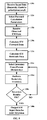
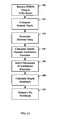
- Apparatus and methods in accordance with this invention implement an iterative process to generate velocity models that may be used for PSDM.
- seismic, gravity and electromagnetic input data are generated for use in a joint inversion (referred to herein as "joint inversion input data").
- initial joint inversion input data are calculated based on observed seismic, gravity and electromagnetic data, and initial velocity, density and/or resistivity models.
- the initial velocity, density and resistivity models may be, for example, user-supplied estimates of velocity, density and resistivity models, respectively.
- a joint inversion is performed on the initial joint inversion input data to produce a multiparametric model that is a function of velocity, density and resistivity parameter distributions.
- the multiparametric model represents the distribution of cross-correlated seismic P-velocity (V P ), density ( ⁇ ) and resistivity (p).
- V P cross-correlated seismic P-velocity
- ⁇ density
- p resistivity
- the separate parameter distributions are extracted from the multiparametric model to form extracted velocity, density and resistivity models.
- the extracted velocity model is used to perform a PSDM, which generates a seismic image in depth in the form of post-migrated image gathers (referred to herein as "CIG gathers").
- a migration velocity analysis is performed on the CIG gathers to evaluate the residual curvature of the CIG gathers to generate seismic image depth-domain residuals.
- the depth-domain residuals are then converted to time-domain residuals (referred to herein as "CIG residuals").
- CIG residuals are analyzed to determine if predetermined quality objectives are satisfied (e.g., if the CIG residuals are below a predetermined threshold). If the quality objectives are satisfied, the extracted velocity model is output as the final velocity model for PSDM, and the process terminates.
- updated seismic, gravity and electromagnetic joint inversion input data are generated.
- the updated joint inversion input data are calculated based on the observed seismic, gravity and electromagnetic data, and the extracted velocity, density and resistivity models from the previous joint inversion.
- the updated seismic joint inversion input data also may be calculated using the CIG residuals from the previous migration velocity analysis.
- a joint inversion is performed on the updated joint inversion input data to produce an updated multiparametric model that is a function of velocity, density and resistivity parameter distributions.
- the separate parameter distributions are extracted from the updated multiparametric model to form updated extracted velocity, density and resistivity models.
- the updated extracted velocity model is used to perform a PSDM, which generates updated CIG gathers.
- a migration velocity analysis is performed on the updated CIG gathers to generate updated CIG residuals.
- the updated CIG residuals are analyzed to determine if the predetermined quality objectives are satisfied. If so, the updated extracted velocity model is output as the final velocity model for PSDM, and the process terminates. If, however, the updated CIG residuals do not meet the predetermined quality objectives, the process repeats by calculating updated seismic, gravity and electromagnetic joint inversion input data, jointly inverting the updated joint inversion input data to generate another updated multiparametric model, and so on, until quality objectives are satisfied.
- this iterative process may continue indefinitely, or may terminate after a predetermined number of iterations have been performed, or upon a user instruction to terminate.
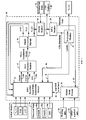
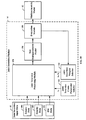
- Exemplary system 10 receives observed data 50, seismogram data 52, well log information 54, other a-priori information 56, and initial velocity, density and resistivity models V P (i), ⁇ (i) and p(i), respectively, and generates CIG gathers 64 and output velocity model V P (o).
- Observed data 50 may include seismic data 50a, gravity data 50b and EM data 50c that may be measured at one or more geographical areas, such as on-shore or off-shore, and at, below or above the Earth's surface (e.g. including airborne measurements).
- Seismic data 50a may include first arrival times (referred to herein as "First Breaks," or "FB").
- Gravity data 50b may include any type of gravity field and gravity field gradients measurements, such as Bouguer anomaly data.
- EM data 50c may include MT data and/or CSEM data.
- Seismogram data 52 may include a record of seismic waveforms as a function of time, of which seismic data 50a may be a subset.
- Well log information 54 may include data generated from sample well logs taken in or near the geographical area in which the observed data 50 were collected.
- Other a-priori information 56 may include any a-priori information that may help a user select homogeneous regions of the velocity, density and resistivity models.
- other a-priori information may include geophysical measurements or geophysical knowledge about the velocity, density and resistivity models that may suggest subdivisions (or grouping) of the model units.
- Exemplary system 10 includes joint inversion input data generation module 12, joint inversion module 14, model extraction module 16, PSDM module 18, migration velocity analysis (“MVA”) module 20, evaluation module 22 and model mask module 24.
- joint inversion input data generation module 12 calculates joint inversion input data 60, which may include seismic joint inversion input data 60a, gravity joint inversion input data 60b and EM joint inversion input data 60c.
- joint inversion input data generation module 12 calculates joint inversion input data 60 based either on the initial velocity, density and resistivity models, V P (i), ⁇ (i) and p(i), respectively, or the extracted velocity, density and resistivity models, V P (e), ⁇ (e) and p(e), respectively.
- update control signal 70 instructs joint inversion input data generation module 12 to calculate joint inversion input data 60 based on initial models V P (i), ⁇ (i) and ⁇ (i).
- Joint inversion module 14 receives the joint inversion input data 60 and generates a multi-parametric model 62.
- Model extraction module 16 extracts velocity, density and resistivity models V P (e), ⁇ (e) and ⁇ (e), respectively, from multi-parametric model 62.
- PSDM module 18 uses the extracted velocity model V P (e) to generate CIG gathers 64, and MVA module 20 calculates CIG residuals 66 and horizon data 68 based on the CIG gathers 64.
- Evaluation module 22 determines if the CIG residuals 66 meet predetermined quality objectives. If the predetermined quality objectives are satisfied, evaluation module 22 outputs the current extracted velocity model V P (e) as the output velocity model V P (o). Otherwise, evaluation module 22 generates an update control signal 70 that instructs joint inversion input data generation module 12 to calculate updated joint inversion input data 60 based on extracted models V P (e), ⁇ (e) and ⁇ (e). As described in more detail below, throughout the joint inversion process, model mask module 24 may be used to specify joint inversion constraints.
- update control signal 70 instructs joint inversion input data generation module 12 to create the initial joint inversion input data 60.
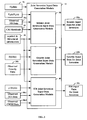
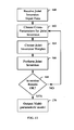
- joint inversion input data generation module 12 receives initial velocity model V P (i), initial density model ⁇ (i), initial resistivity model p(i), observed data 50, and a-priori/structural information 58, and generates initial seismic joint inversion input data 60a, gravity joint inversion input data 60b and EM joint inversion input data 60c.
- joint inversion module 14 receives the seismic joint inversion input data 60a, gravity joint inversion input data 60b and EM joint inversion input data 60c, and performs a joint inversion to generate a multiparametric model 62.
- model extraction module 16 extracts velocity model V P (e), density model ⁇ (e) and resistivity model ⁇ (e) from the multiparametric model 62.
- PSDM module 18 receives the extracted velocity model V P (e) and seismogram data 52, and generates CIG gathers 64.
- MVA module 20 receives CIG gathers 64, and performs a migration velocity analysis to generate CIG residuals 66 and horizon data 68.
- evaluation module 22 determines if CIG residuals 66 meet predetermined quality objectives. For example, evaluation module 22 may determine if CIG residuals 66 are below a predetermined threshold. If so, at step 42, evaluation module 22 outputs the extracted velocity model V P (e) as the output velocity model V P (o).
- PSDM module 18 also may output the current CIG gathers 64, which represent an "optimal" seismic image.
- evaluation module 22 If, however, CIG residuals 66 do not meet the predetermined quality objectives, at step 44, evaluation module 22 generates an update control signal 70 that instructs joint inversion input data generation module 12 to generate updated seismic joint inversion input data 60a, gravity joint inversion input data 60b and EM joint inversion input data 60c based on the extracted models V P (e), ⁇ (e) and ⁇ (e), observed data 50, a-priori/structural information 58, and optionally CIG residuals 66. The process then returns to step 32, wherein joint inversion module 14 receives the updated seismic joint inversion input data 60a, gravity joint inversion input data 60b and EM joint inversion input data 60c, and performs a joint inversion to generate an updated multiparametric model 62. This process continues in an iterative fashion until CIG residuals 66 satisfy the predetermined quality objectives, or until a predetermined number of iterations have been performed or a user terminates the operation of the system.
- model mask module 24 receives well log information 54, other a-priori information 56 and horizon data 68 (if available), and generates a-priori/structural information 58 that is provided to joint inversion input data generation module 12.
- A-priori/structural information 58 constitutes a "constraints inversion mask” that may be used to constrain portions of one or more of the velocity, density and resistivity models during the joint inversion.
- the constraints inversion mask may specify portions of a model in which geophysical parameters are already known (e.g., from well logs), and that should not be included in the unknown parameters to be inverted.
- the constraints inversion mask may be used to delimit portions of a model to be inverted from portions of a model where the user wants to maintain the results of previous iterations (e.g., a layer-stripping approach).
- the model mask may be used to indicate sub-portions of a model where uniformity of parameters is expected during the inversion (e.g., by setting the cross-correlation coefficients of model parameters in a model covariance matrix).
- the constraints may be specified and applied independently, and the constraints inversion mask may include a single mask, or may include multiple masks. That is, a first set of constraints may apply to the seismic portion of the joint inversion, a second set of constraints may apply to the gravity portion of the joint inversion, and a third set of constraints may apply to the resistivity portion of the joint inversion, and the first, second and third sets of constraints may be independent of one another.
- the seismic portion of the joint inversion problem may include constraints that differ from constraints in the gravity portion of the joint inversion problem, and that differ from constraints in the EM portion of the joint inversion problem vice-versa.
- joint inversion input data generation module 12 calculates seismic joint inversion input data 60a, gravity joint inversion input data 60b and EM joint inversion input data 60c used by joint inversion module 14.
- joint inversion input data generation module 12 includes seismic joint inversion input data generation module 80, gravity joint inversion input data generation module 82, and electromagnetic joint inversion input data generation module 84. Each of these modules will be described in turn.
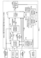
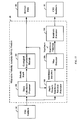
- FIG. 4 illustrates an exemplary seismic joint inversion input data generation module 80, which includes forward calculation processor 90a, residuals calculation processor 92a, velocity inversion module 94a, forward calculation parameters selector 96a, inversion constraints selector 98a, inversion parameters selector 100a, and evaluation module 102a.
- seismic joint inversion input data generation module 80 receives observed FB data 50a and/or CIG residuals 66, velocity models V P (i) and/or V P (e), update control signal 70 and a-priori/structural information 58, and generates seismic joint inversion input data 60a.
- seismic joint inversion input data 60a includes FB residuals data 60a1, velocity forward calculation parameters 60a2, selected velocity inversion constraints 60a3, selected velocity inversion parameters 60a4 and CIG residuals 60a5 (also labelled as CIG residuals 66).
- seismic joint inversion input data generation module 80 receives update control signal 70 and a-priori/structural information 58, and selects velocity model V P (i) or V P (e) based on update control signal 70. For example, for the first iteration, update control signal 70 instructs seismic joint inversion input data generation module 80 to select the initial velocity model V P (i). For subsequent iterations, update control signal 70 instructs seismic joint inversion input data generation module 80 to select the extracted velocity model V P (e) from the previous iteration.
- a user may use forward calculation parameters selector 96a to select velocity forward calculation parameters 60a2, such as the cell dimension of the velocity model, and other similar parameters that govern the forward calculation process.
- FB data 50a which may include FB data at multiple sample points.
- forward calculation processor 90a calculates forward data using the velocity model (V P (i) for the initial iteration or V P (e) for subsequent iterations). Depending on whether CIG data and/or FB data are selected at steps 124 and 127, respectively, forward calculation processor 90a may calculate CIG forward data 60a6 only, FB forward data 104a only, or both CIG forward data 60a6 and FB forward data 104a. If CIG data are selected at step 124, forward calculation processor 90a calculates CIG forward data 60a6 by converting CIG residuals 60a5 from depth residuals to time residuals using common reflection point ("CRP") ray tracing.
- CRP common reflection point
- forward calculation processor 90a calculates FB forward data 104a at the same sample points as observed FB data 50a.
- FB residuals data are calculated. For example, residuals calculation processor 92a may subtract observed FB data 50a sample points from corresponding FB forward data 104a sample points to generate FB residuals data 60a1.
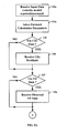
- step 134a constraints and parameters are selected for a "test" velocity inversion.
- constraints and parameters are selected for a "test" velocity inversion.
- a user may use inversion constraints selector 98a to select velocity inversion constraints 60a3 from a-priori/structural information 58.
- inversion parameters selector 100a to select velocity inversion parameters 60a4.
- step 136a a test velocity inversion is performed.
- velocity inversion module 94a receives FB forward data 104a and FB residuals data 60a1 (if FB data are selected at step 127), CIG residuals 60a5 and CIG forward data 60a6 (if CIG data are selected at step124), velocity forward calculation parameters 60a2, selected velocity inversion constraints 60a3 and selected velocity inversion parameters 60a4, and performs a test inversion to generate a "test" velocity model V P (t).
- the test inversion results are evaluated.
- a user may use evaluation module 102a to determine whether the selected velocity inversion constraints 60a3 and selected velocity inversion parameters 60a4 meet predetermined performance objectives.
- the user may use various numerical analysis techniques to evaluate the performance of the test inversion. If the user determines that the selected velocity inversion constraints 60a3 and selected velocity inversion parameters 60a4 meet predetermined performance objectives, at step 140a the seismic joint inversion input data 60a (i.e., FB residuals data 60a1, velocity forward calculation parameters 60a2, selected velocity inversion constraints 60a3, selected velocity inversion parameters 60a4, CIG residuals 60a5 and CIG forward data 60a6) are output to joint inversion module 14.
- FB residuals data 60a1 i.e., FB residuals data 60a1, velocity forward calculation parameters 60a2, selected velocity inversion constraints 60a3, selected velocity inversion parameters 60a4, CIG residuals 60a5 and CIG forward data 60a6
- the process returns to step 134a, and the user may select new velocity inversion constraints 60a3 and/or velocity inversion parameters 60a4.
- gravity joint inversion input data generation module 82 includes forward calculation processor 90b, residuals calculation processor 92b, density inversion module 94b, forward calculation parameters selector 96b, inversion constraints selector 98b, inversion parameters selector 100b, and evaluation module 102b.
- gravity joint inversion input data generation module 82 receives observed gravity data 50b, density models ⁇ (i) and/or ⁇ (e), update control signal 70 and a-priori/structural information 58, and generates gravity joint inversion input data 60b.
- gravity joint inversion input data 60b includes gravity residuals data 60b1, gravity forward calculation parameters 60b2, selected gravity inversion constraints 60b3 and selected gravity inversion parameters 60b4.
- gravity joint inversion input data generation module 82 receives update control signal 70 and a-priori/structural information 58, and selects density model ⁇ (i) or ⁇ (e) based on update control signal 70. For example, for the first iteration, update control signal 70 instructs gravity joint inversion input data generation module 82 to select the initial density model ⁇ (i). For subsequent iterations, update control signal 70 instructs gravity joint inversion input data generation module 82 to select the extracted density model ⁇ (e) from the previous iteration.
- a user may use forward calculation parameters selector 96b to select gravity forward calculation parameters 60b2, such as the cell dimension of the density model, and other similar parameters that govern the forward calculation process.
- gravity joint inversion input data generation module 82 receives observed gravity data 50b, which includes observed gravity data at multiple sample points.
- forward calculation processor 90b calculates gravity forward data 104b using the density model ( ⁇ (i) for the initial iteration or ⁇ (e) for subsequent iterations). In particular, forward calculation processor 90b calculates gravity forward data 104b at the same samples as observed gravity data 50b.
- gravity residuals data are calculated. For example, residuals calculation processor 92b may subtract observed gravity data 50b sample points from corresponding gravity forward data 104b sample points to generate gravity residuals data 60b1.
- step 134b constraints and parameters are selected for a "test" density inversion.
- constraints and parameters are selected for a "test" density inversion.
- a user may use inversion constraints selector 98b to select density inversion constraints 60b3 from a-priori/structural information 58.
- inversion parameters selector 100b to select density inversion parameters 60b4.
- step 136b a test density inversion is performed.
- density inversion module 94b receives gravity forward data 104b, gravity residuals data 60b1, gravity forward calculation parameters 60b2, selected density inversion constraints 60b3 and selected density inversion parameters 60b4, and performs a test inversion to generate a "test" density model ⁇ (t).
- the test inversion results are evaluated.
- a user may use evaluation module 102b to determine whether the selected density inversion constraints 60b3 and selected density inversion parameters 60b4 meet predetermined performance objectives.
- the user may use various numerical analysis techniques to evaluate the performance of the test inversion. If the user determines that the selected density inversion constraints 60b3 and selected density inversion parameters 60b4 meet predetermined performance objectives, at step 140b the joint inversion gravity input data 60b (i.e., gravity residuals data 60b1, gravity forward calculation parameters 60b2, selected gravity inversion constraints 60b3 and selected gravity inversion parameters 60b4) are output to joint inversion module 14.
- the process returns to step 134b, and the user may select new density inversion constraints 60b3 and/or density inversion parameters 60b4.
- EM joint inversion input data generation module 84 includes forward calculation processor 90c, residuals calculation processor 92c, resistivity inversion module 94c, forward calculation parameters selector 96c, inversion constraints selector 98c, inversion parameters selector 100c, and evaluation module 102c.
- EM joint inversion input data generation module 84 receives observed EM data 50c (e.g., observed MT data 50c1 and/or observed CSEM data 50c2), resistivity models ⁇ (i) and/or ⁇ (e), update control signal 70 and a-priori/structural information 58, and generates EM joint inversion input data 60c.
- EM joint inversion input data 60c includes EM residuals data 60c1 (e.g., MT residuals data 60c1a and/or CSEM residuals data 60c1b), EM forward calculation parameters 60c2, selected resistivity inversion constraints 60c3 and selected resistivity inversion parameters 60c4.
- EM joint inversion input data generation module 84 receives update control signal 70 and a-priori/structural information 58, and selects resistivity model ⁇ (i) or ⁇ (e) based on the value of update control signal 70. For example, for the first iteration, update control signal 70 instructs EM joint inversion input data generation module 84 to select the initial resistivity model ⁇ (i). For subsequent iterations, update control signal 70 instructs EM joint inversion input data generation module 84 to select the extracted resistivity model ⁇ (e) from the previous iteration.
- a user may use forward calculation parameters selector 96c to select EM forward calculation parameters 60c2, such as the cell dimension of the resistivity model, and other similar parameters that govern the forward calculation process.
- EM joint inversion input data generation module 84 receives observed EM data 50c, which may include MT data 50c1 at multiple sample points and/or observed CSEM data 50c2 at multiple sample points.
- forward calculation processor 90c calculates EM forward data 104c using the selected resistivity model (p(i) for the initial iteration or ⁇ (e) for subsequent iterations).
- forward calculation processor 90c calculates MT forward data 104c1 at the same samples as observed MT data 50c1. If observed EM data 50c includes observed CSEM data 50c2, forward calculation processor 90c calculates CSEM forward data 104c2 at the same samples as observed CSEM data 50c2.
- EM residuals data are calculated. For example, if observed EM data 50c includes observed MT data 50c1, residuals calculation processor 92c may subtract observed MT data 50c1 sample points from corresponding MT forward data 104c1 sample points to generate MT residuals data 60c1a. If observed EM data 50c includes observed CSEM data 50c2, residuals calculation processor 92c may subtract observed CSEM data 50c2 sample points from corresponding CSEM forward data 104c2 sample points to generate CSEM residuals data 60clb.
- step 134c constraints and parameters are selected for a "test" resistivity inversion.
- constraints and parameters are selected for a "test" resistivity inversion.
- a user may use inversion constraints selector 98c to select resistivity inversion constraints 60c3 from a-priori/structural information 58.
- inversion parameters selector 100c to select resistivity inversion parameters 60c4.
- step 136c a test resistivity inversion is performed.
- resistivity inversion module 94c receives MT forward data 104c1 and/or CSEM forward data 104c2, MT residuals data 60c1a and/or CSEM residuals data 60c1b, EM forward calculation parameters 60c2, selected resistivity inversion constraints 60c3 and selected resistivity inversion parameters 60c4, and performs a test inversion to generate a "test" resistivity model p(t).
- the test inversion results are evaluated.
- a user may use evaluation module 102c to determine whether the selected resistivity inversion constraints 60c3 and selected resistivity inversion parameters 60c4 meet predetermined performance objectives. For example, the user may use various numerical analysis techniques to evaluate the performance of the test inversion. If the user determines that the selected resistivity inversion constraints 60c3 and selected resistivity inversion parameters 60c4 meet predetermined performance objectives, at step 140c the EM joint inversion input data 60c (i.e., EM residuals data 60c1, EM forward calculation parameters 60c2, selected resistivity inversion constraints 60c3 and selected resistivity inversion parameters 60c4) are output to joint inversion module 14.
- EM joint inversion input data 60c i.e., EM residuals data 60c1, EM forward calculation parameters 60c2, selected resistivity inversion constraints 60c3 and selected resistivity inversion parameters 60c4
- the process returns to step 134c, and the user may select new resistivity inversion constraints 60c3 and/or density inversion parameters 60c4.
- joint inversion module 14 receives joint inversion input data 60 and generates multi-parametric model 62.
- joint inversion module 14 includes joint inversion processing module 150, joint inversion cross-parameter selector module 152, joint inversion weights selector module 154, and evaluation module 158.
- joint inversion processing module 150 receives joint inversion input data 60 (i.e., seismic joint inversion input data 60a, gravity joint inversion input data 60b and EM joint inversion input data 60c).
- joint inversion cross-parameter selector module 152 is used to select joint inversion cross-parameter weights c k .
- a user may use cross-parameter selector module 152 to specify cross-parameter empirical relationships, which indicate links between physical values to be inverted, and cross-parameters structural relationships, which impose pattern similarity on the different inverted models.
- joint inversion weights selector module 154 is used to specify relative weights that are to be applied to the seismic, gravity and EM methodologies. For example, a user may use joint inversion weights selector module 154 to specify relative joint inversion weights a k , b k .
- a joint inversion is performed.
- joint inversion processing module 150 may perform a joint inversion through minimization of an objective function that follows from the application of well-established least squares inverse problem theory.
- the first term is the weighted sum of data square errors (a k are the joint inversion weights chosen by the user, while C D,k -1 is the inverse data covariance matrix for the k-th domain)
- the second term is the weighted sum of different regularization terms, one for each domain (b k are weights chosen by the user, ⁇ k is a generic regularization function)
- the third term is the weighted sum of different kind of linking terms between different domains (c k are user defined weights, ⁇ k are linking functions among parameters and N l is the total number of links used); vector
- t x ⁇ y ⁇ z 2 ⁇ m 1 x y z ⁇ ⁇ m 2 x ⁇ y ⁇ z 2
- m 1 and m 2 are two models (e.g., velocity and density, velocity and resistivity, and resistivity and gravity).
- Joint inversion is carried out minimizing the objective function with respect to the multiparametric model vector.
- the model parameterization can be different and adaptive (cells of variable dimension in horizontal and vertical directions) for the different methodologies according to the different expected accuracy of the various methodologies used in the joint inversion.
- test multiparametric model 156 is evaluated for quality requirements and geological reliability.
- a user may use evaluation module 158 to determine whether test multiparametric model 156 meets predetermined performance objectives and is consistent with observed geological data. If the user determines that test multiparametric model 156 meets predetermined performance objectives, at step 170 evaluation module outputs test multiparametric model 156 as multiparametric model 62. If, however, the user determines that test multiparametric model 156 does not meet predetermined performance objectives, the process returns to step 162, and the user may select new joint inversion cross-parameter weights and/or joint inversion weights (at step 164).
- model extraction module 16 extracts velocity, density and resistivity models V P (e), ⁇ (e) and ⁇ (e), respectively, from multi-parametric model 62.
- model extraction module 16 extracts velocity, density and resistivity models V P (e), ⁇ (e) and ⁇ (e), respectively, from multi-parametric model 62.
- Persons of ordinary skill in the art will understand that any conventional technique may be used to extract velocity, density and resistivity models V P (e), ⁇ (e) and ⁇ (e), respectively, from multi-parametric model 62.
- PSDM module 18 uses the extracted velocity model V P (e) to generate CIG gathers 64.
- any conventional technique may be used to generate CIG gathers 64 from the extracted velocity model V P (e). For example, a Kirchhoff pre-stack depth migration technique or other similar technique may be used.
- MVA module 20 calculates CIG residuals 66 and horizon data 68 based on CIG gathers 64.
- MVA module 20 includes stack calculation processor 180, geological interpretation module 182, depth domain semblance function processor 184, max detector 186 and depth residuals processor 188.
- MVA module 20 receives CIG gathers 64 from PSDM module 18.
- stack calculation processor 180 computes a seismic stack from CIG gathers 64.
- stack calculation processor 180 sums CIG gathers 64 to generate a seismic image of the underground geology.
- geological interpretation module 182 may be used to generate a set of horizon data 68 from the seismic stack.
- a user may use geological interpretation module 182 to select the shapes and geometries of geological units, which generates the set of horizon data 68, which may be expressed as line segments.
- depth domain semblance function processor generates a depth domain semblance function from CIG gathers 64 and horizon data 68.
- the depth-domain semblance function is maximum where the maximum residual is present.
- max detector 186 selects the maximum of the semblance function.
- residuals processor 188 calculates depth residuals from the maximum of the semblance function, converts the depth residuals to time residuals, and outputs the result as CIG residuals 66.
- evaluation module 22 receives CIG residuals 66 from MVA modules 20, and then determines if the CIG residuals 66 meet predetermined quality objectives. For example, evaluation module 22 may determine if CIG residuals 66 are less than a predetermined threshold. If so, evaluation module 22 outputs the extracted velocity models V P (e) as the output velocity model V P (o). Otherwise, evaluation module 22 sets update control signal 70 to 1 to instruct joint inversion data generation module 12 to generate updated joint inversion input data 60.
- Apparatus and methods in accordance with this invention may be implemented as a computer-implemented method, system, and computer program product.
- this invention may be implemented within a network environment (e.g., the Internet, a wide area network ("WAN"), a local area network ("LAN”), a virtual private network (“VPN”), etc.), or on a stand-alone computer system.
- a network environment e.g., the Internet, a wide area network (“WAN”), a local area network (“LAN”), a virtual private network (“VPN”), etc.
- communication links may comprise addressable connections that may utilize any combination of wired and/or wireless transmission methods.
- connectivity could be provided by conventional TCP/IP sockets-based protocol, and an Internet service provider could be used to establish connectivity to the Internet.
- the present invention could be implemented on a computer system, such as computer system 300 that includes a processing unit 310, a memory 312, a bus 314, input/output ("I/O") interfaces 316 and external devices 318.
- Processing unit 310 may be a computer or processing unit of any type that is capable of performing the functions described herein.
- Memory 312 is capable of storing a set of machine readable instructions (i.e., computer software) executable by processing unit 310 to perform the desired functions.
- Memory 312 is any type of media or device for storing information in a digital format on a permanent or temporary basis, such as, e.g., a magnetic media, optical media, flash memory, random access memory, or other similar memory.
- memory 312 includes a joint inversion software application 320, which is a software program that provides the functions of the present invention.
- joint inversion software application 320 may be stored on storage system 322.
- Processing unit 310 executes the joint inversion software application 320. While executing computer program code 320, processing unit 310 can read and/or write data to/from memory 312, storage system 322 and/or I/O interfaces 316.
- Bus 314 provides a communication link between each of the components in computer system 300.
- External devices 318 can comprise any devices (e.g., keyboard, pointing device, display, etc.) that enable a user to interact with computer system 300 and/or any devices (e.g., network card, modem, etc.) that enable computer system 300 to communicate with one or more other computing devices.
- devices e.g., keyboard, pointing device, display, etc.
- devices e.g., network card, modem, etc.
- Computer system 300 may include two or more computing devices (e.g., a server cluster) that communicate over a network to perform the various process steps of the invention.
- Embodiments of computer system 300 can comprise any specific purpose computing article of manufacture comprising hardware and/or computer program code for performing specific functions, any computing article of manufacture that comprises a combination of specific purpose and general purpose hardware/software, or the like.
- the program code and hardware can be created using standard programming and engineering techniques, respectively.
- processing unit 310 can comprise a single processing unit, or can be distributed across one or more processing units in one or more locations, e.g., on a client and server.
- memory 312 and/or storage system 322 can comprise any combination of various types of data storage and/or transmission media that reside at one or more physical locations.
- I/O interfaces 316 can comprise any system for exchanging information with one or more external devices 318.
- one or more additional components e.g., system software, math co-processing unit, etc.
- additional components e.g., system software, math co-processing unit, etc.
- Storage system 322 may include one or more storage devices, such as a magnetic disk drive or an optical disk drive. Alternatively, storage system 322 may include data distributed across, for example, a LAN, WAN or a storage area network ("SAN") (not shown). Although not shown in FIG. 14 , additional components, such as cache memory, communication systems, system software, etc., may be incorporated into computer system 300.
- storage system 322 may include one or more storage devices, such as a magnetic disk drive or an optical disk drive.
- storage system 322 may include data distributed across, for example, a LAN, WAN or a storage area network (“SAN”) (not shown).
- SAN storage area network
- additional components such as cache memory, communication systems, system software, etc., may be incorporated into computer system 300.
Landscapes
- Physics & Mathematics (AREA)
- Life Sciences & Earth Sciences (AREA)
- Engineering & Computer Science (AREA)
- Remote Sensing (AREA)
- General Life Sciences & Earth Sciences (AREA)
- General Physics & Mathematics (AREA)
- Geophysics (AREA)
- Acoustics & Sound (AREA)
- Environmental & Geological Engineering (AREA)
- Geology (AREA)
- Geophysics And Detection Of Objects (AREA)
- Management, Administration, Business Operations System, And Electronic Commerce (AREA)
Claims (11)
- Verfahren zur Erstellung eines Geschwindigkeitsmodells für Vorstapeltiefenmigration, wobei das Verfahren umfasst:Erstellen (30) von anfänglichen Eingabedaten zur gemeinsamen Invertierung, die seismische, Schwerkraft- und elektromagnetische Daten umfassen;gemeinsames Invertieren (32) der anfänglichen Eingabedaten zur gemeinsamen Invertierung, um ein multiparametrisches Modell zu erstellen, das Geschwindigkeits-, Dichte- und Widerstandsparameterverteilungen umfasst;Extrahieren (34) von Geschwindigkeitsparametern, Dichteparametern und Widerstandsparametern aus dem multiparametrischen Modell, um ein extrahiertes Geschwindigkeitsmodell, ein extrahiertes Dichtemodell bzw. ein extrahiertes Widerstandsmodell zu bilden;Berechnen (36) eines ersten seismischen Bildes unter Verwendung des extrahierten Geschwindigkeitsmodells;Bestimmen (40), ob das berechnete erste seismische Bild ein vorgegebenes Qualitätskriterium erfüllt;Ausgeben (42) des extrahierten Geschwindigkeitsmodells als das Geschwindigkeitsmodell, wenn das vorgegebene Qualitätskriterium erfüllt wird; undwobei, wenn das vorgegebene Qualitätskriterium nicht erfüllt wird, das Verfahren ferner umfasst:Erstellen (44) von aktualisierten Eingabedaten zur gemeinsamen Invertierung basierend auf den beobachteten seismischen, Schwerkraft- und elektromagnetischen Daten und den extrahierten Geschwindigkeits-, Dichte- und Widerstandsmodellen;gemeinsames Invertieren (32) der aktualisierten Eingabedaten zur gemeinsamen Invertierung, um ein aktualisiertes multiparametrisches Modell zu erstellen, das Geschwindigkeits-, Dichte- und Widerstandsparameterverteilungen umfasst;Extrahieren (34) von Geschwindigkeitsparametern, Dichteparametern und Widerstandsparametern aus dem aktualisierten multiparametrischen Modell, um ein aktualisiertes extrahiertes Geschwindigkeitsmodell, ein aktualisiertes extrahiertes Dichtemodell bzw. ein aktualisiertes extrahiertes Widerstandsmodell zu bilden;Berechnen (36) eines aktualisierten seismischen Bildes unter Verwendung des aktualisierten extrahierten Geschwindigkeitsmodells;Bestimmen (40), ob das berechnete aktualisierte seismische Bild das vorgegebene Qualitätskriterium erfüllt;Ausgeben (42) des aktualisierten extrahierten Geschwindigkeitsmodells als das Geschwindigkeitsmodell, wenn das vorgegebene Qualitätskriterium erfüllt wird.
- Verfahren nach Anspruch 1, wobei das Erstellen anfänglicher Eingabedaten zur gemeinsamen Invertierung umfasst:Empfangen von beobachteten seismischen, Schwerkraft- und elektromagnetischen Daten;Empfangen von anfänglichen Geschwindigkeits-, Dichte- und Widerstandsmodellen; undBerechnen der anfänglichen Eingabedaten zur gemeinsamen Invertierung basierend auf den beobachteten seismischen, Schwerkraft- und elektromagnetischen Daten und den anfänglichen Geschwindigkeits-, Dichte- und Widerstandsmodellen.
- Verfahren nach Anspruch 2, wobei die beobachteten seismischen Daten erste Ankunftszeitdaten umfassen.
- Verfahren nach Anspruch 2, wobei die beobachteten Schwerkraftdaten Schwerkraftrestgrößen umfassen.
- Verfahren nach Anspruch 2, wobei die beobachteten elektromagnetischen Daten magnetotellurische Daten und/oder elektromagnetische Daten von kontrollierten Quellen umfassen.
- Verfahren nach Anspruch 1, wobei das Berechnen des ersten seismischen Bildes ein Durchführen einer Vorstapeltiefenmigration unter Verwendung des anfänglichen Geschwindigkeitsmodells umfasst.
- Verfahren nach Anspruch 1, wobei das erste seismische Bild ein seismisches Tiefenbild umfasst, und das Bestimmen ein Bestimmen einer Restkrümmung des seismischen Vorstapeltiefenbilds umfasst, um seismische Tiefenbereichsbildrestgrößen zu erzeugen.
- Verfahren nach Anspruch 7, wobei das Bestimmen einer Restkrümmung ein Durchführen einer Migrationsgeschwindigkeitsanalyse am seismischen Tiefenbild umfasst.
- Verfahren nach Anspruch 7, ferner umfassend:Konvertieren der seismischen Tiefenbereichsrestgrößen in seismische Zeitbereichsrestgrößen;Vergleichen der seismischen Zeitbereichsrestgrößen mit einer vorgegebenen Schwelle; undAusgeben des anfänglichen Geschwindigkeitsmodells als das Geschwindigkeitsmodell, wenn die seismischen Zeitbereichsrestgrößen unter der vorgegebenen Schwelle liegen.
- Verfahren nach Anspruch 1, ferner umfassend ein iteratives Wiederholen der Schritte des Erstellens, gemeinsamen Invertierens, Extrahierens, Berechnens und Bestimmens, bis das berechnete aktualisierte seismische Bild das vorgegebene Qualitätskriterium erfüllt, bis eine vorgegebene Anzahl von Iterationen durchgeführt wurde, oder bis zu einem Beendigungsbefehl eines Anwenders.
- System zum Erstellen eines Geschwindigkeitsmodells für Vorstapeltiefenmigration zur geophysikalischen Erkundung, wobei das System einen Computer umfasst, der einen Prozessor und eine Speichervorrichtung zum Durchführen eines Verfahrens nach Anspruch 1 bis 10 umfasst.
Applications Claiming Priority (2)
| Application Number | Priority Date | Filing Date | Title |
|---|---|---|---|
| PCT/IT2006/000636 WO2008029420A1 (en) | 2006-09-04 | 2006-09-04 | Method for building velocity models for pre-stack depth migration via the simultaneous joint inversion of seismic, gravity and magnetotelluric data |
| US11/829,551 US7805250B2 (en) | 2006-09-04 | 2007-07-27 | Methods and apparatus for geophysical exploration via joint inversion |
Publications (2)
| Publication Number | Publication Date |
|---|---|
| EP2020609A1 EP2020609A1 (de) | 2009-02-04 |
| EP2020609B1 true EP2020609B1 (de) | 2012-11-21 |
Family
ID=38640102
Family Applications (3)
| Application Number | Title | Priority Date | Filing Date |
|---|---|---|---|
| EP13180923.8A Active EP2667224B1 (de) | 2006-09-04 | 2006-09-04 | Verfahren zur Herstellung von Geschwindigkeitsmodellen für Prestack-Tiefenmigration über gleichzeitige gemeinsame Inversion von seismischen, Schwerkraft- und magnetotellurischen Daten. |
| EP06809975.3A Active EP2062071B1 (de) | 2006-09-04 | 2006-09-04 | Verfahren zum aufbau von geschwindigkeitsmodellen für vorstapeltiefenmigration über gleichzeitige verbundinversion von seismischen, schwerkrafts- und magnetotellurischen daten |
| EP08161220A Active EP2020609B1 (de) | 2006-09-04 | 2008-07-25 | Verfahren und Vorrichtung zur geophysikalischen Erkundung durch gemeinsame Dateninvertierung |
Family Applications Before (2)
| Application Number | Title | Priority Date | Filing Date |
|---|---|---|---|
| EP13180923.8A Active EP2667224B1 (de) | 2006-09-04 | 2006-09-04 | Verfahren zur Herstellung von Geschwindigkeitsmodellen für Prestack-Tiefenmigration über gleichzeitige gemeinsame Inversion von seismischen, Schwerkraft- und magnetotellurischen Daten. |
| EP06809975.3A Active EP2062071B1 (de) | 2006-09-04 | 2006-09-04 | Verfahren zum aufbau von geschwindigkeitsmodellen für vorstapeltiefenmigration über gleichzeitige verbundinversion von seismischen, schwerkrafts- und magnetotellurischen daten |
Country Status (6)
| Country | Link |
|---|---|
| US (2) | US8363509B2 (de) |
| EP (3) | EP2667224B1 (de) |
| CA (1) | CA2638247A1 (de) |
| MX (1) | MX2008009584A (de) |
| NO (1) | NO340762B1 (de) |
| WO (1) | WO2008029420A1 (de) |
Cited By (2)
| Publication number | Priority date | Publication date | Assignee | Title |
|---|---|---|---|---|
| CN104216006A (zh) * | 2013-06-04 | 2014-12-17 | 中国石油化工股份有限公司 | 利用重磁电震同步联合参数模型进行提高成像质量的方法 |
| US9195783B2 (en) | 2010-08-16 | 2015-11-24 | Exxonmobil Upstream Research Company | Reducing the dimensionality of the joint inversion problem |
Families Citing this family (110)
| Publication number | Priority date | Publication date | Assignee | Title |
|---|---|---|---|---|
| WO2008029420A1 (en) * | 2006-09-04 | 2008-03-13 | Geosystem S.R.L. | Method for building velocity models for pre-stack depth migration via the simultaneous joint inversion of seismic, gravity and magnetotelluric data |
| US8064287B2 (en) * | 2006-12-28 | 2011-11-22 | Rock Solid Images, Inc. | Method for interpreting seismic data and controlled source electromagnetic data to estimate subsurface reservoir properties |
| US20090083006A1 (en) * | 2007-09-20 | 2009-03-26 | Randall Mackie | Methods and apparatus for three-dimensional inversion of electromagnetic data |
| US8738341B2 (en) * | 2007-12-21 | 2014-05-27 | Schlumberger Technology Corporation | Method for reservoir characterization and monitoring including deep reading quad combo measurements |
| US8744817B2 (en) * | 2007-12-21 | 2014-06-03 | Schlumberger Technology Corporation | Method for upscaling a reservoir model using deep reading measurements |
| US8275592B2 (en) * | 2008-04-07 | 2012-09-25 | Westerngeco L.L.C. | Joint inversion of time domain controlled source electromagnetic (TD-CSEM) data and further data |
| US7791981B2 (en) * | 2008-05-15 | 2010-09-07 | Shell Oil Company | Velocity analysis for VSP data |
| US8098542B2 (en) * | 2009-01-05 | 2012-01-17 | Pgs Geophysical As | Combined electromagnetic and seismic acquisition system and method |
| WO2010104537A1 (en) * | 2009-03-11 | 2010-09-16 | Exxonmobil Upstream Research Company | Adjoint-based conditioning of process-based geologic models |
| AU2009341851B2 (en) | 2009-03-11 | 2015-07-16 | Exxonmobil Upstream Research Company | Gradient-based workflows for conditioning of process-based geologic models |
| WO2011071812A2 (en) * | 2009-12-07 | 2011-06-16 | Geco Technology B.V. | Simultaneous joint inversion of surface wave and refraction data |
| US20120002504A1 (en) * | 2010-03-01 | 2012-01-05 | Everhard Muyzert | Gravity measurements in marine, land and/or seabed seismic applications |
| CN101900833B (zh) * | 2010-06-02 | 2012-05-23 | 西安石油大学 | 一种地震散射p-p波成像速度分析方法 |
| WO2011154762A1 (en) * | 2010-06-07 | 2011-12-15 | Total Sa | Method for analyzing seismic data |
| US10379255B2 (en) | 2010-07-27 | 2019-08-13 | Exxonmobil Upstream Research Company | Inverting geophysical data for geological parameters or lithology |
| WO2012027848A1 (en) * | 2010-09-03 | 2012-03-08 | Geosoft Inc. | Method and system for modeling anomalous density zones in geophysical exploration |
| US8861309B2 (en) * | 2011-01-31 | 2014-10-14 | Chevron U.S.A. Inc. | Exploitation of self-consistency and differences between volume images and interpreted spatial/volumetric context |
| AU2012212530B2 (en) * | 2011-01-31 | 2015-07-09 | Chevron U.S.A. Inc. | Exploitation of self-consistency and differences between volume images and interpreted spatial/volumetric context |
| GB2502924A (en) * | 2011-04-22 | 2013-12-11 | Baker Hughes Inc | Increasing the resolution of VSP AVA analysis through using borehole gravity information |
| WO2012166228A1 (en) * | 2011-06-02 | 2012-12-06 | Exxonmobil Upstream Research Company | Joint inversion with unknown lithology |
| WO2012173718A1 (en) * | 2011-06-17 | 2012-12-20 | Exxonmobil Upstream Research Company | Domain freezing in joint inversion |
| EP2734866B1 (de) * | 2011-07-21 | 2020-04-08 | Exxonmobil Upstream Research Company | Adaptive gewichtung geophysikalischer datentypen in einer joint-inversion |
| CN102901985B (zh) * | 2011-07-25 | 2016-11-09 | 中国石油化工股份有限公司 | 一种适用于起伏地表的深度域层速度修正方法 |
| US9045967B2 (en) * | 2011-07-26 | 2015-06-02 | Schlumberger Technology Corporation | System and method for controlling and monitoring a drilling operation using refined solutions from a panistic inversion |
| KR101157792B1 (ko) * | 2011-12-06 | 2012-06-19 | 한국지질자원연구원 | 구조화 지수를 이용한 3차원 지질구조 해석방법 |
| CN102590860B (zh) * | 2011-12-31 | 2014-06-11 | 中国石油集团西北地质研究所 | 基于地震波初至信息的反射波建模方法 |
| US9366771B2 (en) | 2012-07-26 | 2016-06-14 | Chevron U.S.A. Inc. | System and method for migration velocity modeling |
| CN103809216B (zh) * | 2012-11-12 | 2016-08-17 | 中国石油天然气集团公司 | 一种电阻率数据与地震数据联合速度建场方法 |
| US20140200816A1 (en) * | 2013-01-14 | 2014-07-17 | Westerngeco L.L.C. | Seismic data processing |
| US10261215B2 (en) | 2013-04-02 | 2019-04-16 | Westerngeco L.L.C. | Joint inversion of geophysical attributes |
| US9846255B2 (en) | 2013-04-22 | 2017-12-19 | Exxonmobil Upstream Research Company | Reverse semi-airborne electromagnetic prospecting |
| US10482996B2 (en) | 2013-05-06 | 2019-11-19 | Schlumberger Technology Corporation | Systems and methods for determining relative geochemical data |
| GB2514788A (en) * | 2013-06-04 | 2014-12-10 | Total E & P Uk Ltd | Method of constraining seismic inversion |
| US11092710B2 (en) | 2013-06-27 | 2021-08-17 | Pgs Geophysical As | Inversion techniques using streamers at different depths |
| US10459100B2 (en) | 2013-06-27 | 2019-10-29 | Pgs Geophysical As | Survey techniques using streamers at different depths |
| US9651707B2 (en) | 2013-06-28 | 2017-05-16 | Cgg Services Sas | Methods and systems for joint seismic and electromagnetic data recording |
| CN104635261B (zh) * | 2013-11-13 | 2018-04-13 | 中国石油化工股份有限公司 | 山前带重磁电震联合分体建模方法 |
| RU2016131935A (ru) | 2014-01-14 | 2018-02-16 | Бейкер Хьюз Инкорпорейтед | Способ обнаружения смещения фронта подвижной текучей среды комбинацией электрических и гравиметрических измерений в стволах скважин |
| CN103869369B (zh) * | 2014-03-13 | 2017-02-15 | 中国石油集团川庆钻探工程有限公司地球物理勘探公司 | 利用剩余曲率对层速度进行校正的方法 |
| US9852373B2 (en) * | 2014-06-02 | 2017-12-26 | Westerngeco L.L.C. | Properties link for simultaneous joint inversion |
| CN104199101A (zh) * | 2014-09-10 | 2014-12-10 | 中国科学院地质与地球物理研究所 | 复杂地形条件下地震波传播复杂性定量分析方法 |
| US9470811B2 (en) | 2014-11-12 | 2016-10-18 | Chevron U.S.A. Inc. | Creating a high resolution velocity model using seismic tomography and impedance inversion |
| CN104360385B (zh) * | 2014-11-26 | 2017-09-22 | 中国石油集团川庆钻探工程有限公司地球物理勘探公司 | 结合地震地质认识综合建立初始深度层速度模型的方法 |
| CN104536043B (zh) * | 2014-12-26 | 2017-12-05 | 中国石油天然气股份有限公司 | 一种深度域整体速度模型融合方法及装置 |
| CN104793247B (zh) * | 2015-03-12 | 2017-10-17 | 中国石油天然气集团公司 | 近地表速度建模方法及建模装置 |
| US10668711B2 (en) | 2015-06-02 | 2020-06-02 | E I Du Pont De Nemours And Company | Printing form precursor, a process for making the precursor, and a method for preparing a printing form from the precursor |
| CN105005097B (zh) * | 2015-07-17 | 2017-07-07 | 中国石油化工股份有限公司 | 利用重力、磁力、电磁、地震资料综合识别火成岩方法 |
| US10067255B2 (en) | 2015-09-04 | 2018-09-04 | Saudi Arabian Oil Company | Automatic quality control of seismic travel time |
| CN105301636B (zh) * | 2015-10-10 | 2017-09-01 | 中国石油天然气集团公司 | 速度模型的建立方法和装置 |
| US10386519B2 (en) | 2015-12-18 | 2019-08-20 | Saudi Arabian Oil Company | Automated near surface analysis by surface-consistent refraction methods |
| CN105954798B (zh) * | 2016-04-26 | 2019-05-07 | 中国石油天然气集团公司 | 一种确定起伏地表的叠前时间偏移速度的方法和装置 |
| AU2017267389A1 (en) | 2016-05-20 | 2018-11-15 | Exxonmobil Research And Engineering Company | Shape-based geophysical parameter inversion |
| US10067252B2 (en) | 2016-07-25 | 2018-09-04 | Chevron U.S.A. Inc. | Methods and systems for identifying a clathrate deposit |
| CN106199704B (zh) * | 2016-09-13 | 2018-04-24 | 中国海洋石油集团有限公司 | 一种三维三分量海底电缆地震资料速度建模方法 |
| CN106772589B (zh) * | 2017-02-27 | 2018-11-02 | 中国石油大学(北京) | 一种叠前地震反演方法及装置 |
| CN107491411B (zh) * | 2017-06-23 | 2020-07-17 | 中国海洋大学 | 基于n阶多项式密度函数的重力异常反演方法 |
| CN107748399B (zh) * | 2017-09-12 | 2019-12-31 | 中国石油化工股份有限公司 | 利用重力界面反演识别山前带深部构造层方法 |
| CN107644134B (zh) * | 2017-09-20 | 2019-01-22 | 北京安怀信科技股份有限公司 | 一种动力学验模工具 |
| CN107765341A (zh) * | 2017-10-20 | 2018-03-06 | 中国地质大学(北京) | 一种确定地层剩余密度的方法 |
| CN108008459B (zh) * | 2017-11-28 | 2019-11-01 | 北京中科地物能源技术有限公司 | 一种获得剩余重力异常的方法及装置 |
| CN108107478B (zh) * | 2017-12-25 | 2019-06-04 | 湖南科技大学 | 大地电磁同步探测与实时反演方法及系统 |
| CN108304618B (zh) * | 2018-01-05 | 2019-05-24 | 台州创兴环保科技有限公司 | 一种重力数据与大地电磁数据联合反演方法 |
| US11163080B2 (en) | 2018-05-18 | 2021-11-02 | Repsol Exploración, S.A | Computer implemented method for generating a subsurface rock and/or fluid model of a determined domain |
| CN110826583A (zh) * | 2018-08-14 | 2020-02-21 | 珠海格力电器股份有限公司 | 故障的确定方法、装置、存储介质及电子装置 |
| CN110968930B (zh) * | 2018-09-30 | 2023-03-21 | 中国石油化工股份有限公司 | 一种地质体变属性插值方法及系统 |
| CN109782336A (zh) * | 2018-12-18 | 2019-05-21 | 中国石油天然气集团有限公司 | 一种快速局部地震成像位置微调方法及装置 |
| CN111624657B (zh) * | 2019-02-28 | 2023-02-07 | 中海石油(中国)有限公司 | 一种可用于全波形反演技术的提取子波的方法 |
| CN110794469B (zh) * | 2019-03-05 | 2021-08-20 | 中国石油化工股份有限公司 | 基于最小地质特征单元约束的重力反演方法 |
| CN109884700B (zh) * | 2019-03-20 | 2021-02-26 | 中国石油化工股份有限公司 | 多信息融合地震速度建模方法 |
| CN110058317B (zh) * | 2019-05-10 | 2020-09-08 | 成都理工大学 | 航空瞬变电磁数据和航空大地电磁数据联合反演方法 |
| CN110221344B (zh) * | 2019-06-17 | 2020-08-28 | 中国地质大学(北京) | 一种地壳三维密度结构的地震全波形与重力联合反演方法 |
| CN110361742B (zh) * | 2019-06-21 | 2021-03-26 | 中国人民解放军国防科技大学 | 一种基于星载三频毫米波雷达的云雨微物理参数反演方法 |
| CN110187336B (zh) * | 2019-06-28 | 2021-01-12 | 电子科技大学 | 一种基于分布式phd的多站雷达站址定位和联合跟踪方法 |
| CN110955746B (zh) * | 2019-10-22 | 2022-03-22 | 中国科学院信息工程研究所 | 一种电磁数据收集处理装置及方法 |
| CN110879412A (zh) * | 2019-10-31 | 2020-03-13 | 南方科技大学 | 地下横波速度反演方法、装置、计算设备及存储介质 |
| CN110989032B (zh) * | 2019-11-23 | 2022-06-28 | 北京地大惠信科技发展有限公司 | 一种基于倾斜角的重力水平总梯度断裂识别方法 |
| NO346380B1 (en) * | 2019-12-05 | 2022-07-04 | Univ Oslo | Fluid identification and saturation estimation using CSEM and seismic data |
| US11725510B2 (en) * | 2020-01-03 | 2023-08-15 | Manzar Fawad | Fluid identification and saturation estimation using CSEM and seismic data |
| CN111175824B (zh) * | 2020-01-06 | 2022-07-12 | 中国石油化工股份有限公司 | 岩相驱动下的时频联合域地震反演方法 |
| CN111221035B (zh) * | 2020-01-08 | 2021-04-02 | 中国海洋大学 | 一种地震反射波斜率和重力异常数据联合反演方法 |
| CN111639865B (zh) * | 2020-06-02 | 2021-03-19 | 中国气象局气象探测中心 | 一种高铁沿线气象灾害发生风险分析方法 |
| CN111722284B (zh) * | 2020-06-28 | 2021-03-09 | 成都捷科思石油天然气技术发展有限公司 | 一种基于道集数据建立速度深度模型的方法 |
| CN111856597B (zh) * | 2020-08-05 | 2023-03-21 | 中国海洋大学 | 拖曳式海洋电磁地层电阻率与接收站位置联合反演方法 |
| CN111880235B (zh) * | 2020-08-05 | 2023-03-28 | 中国海洋大学 | 海洋电磁地层各向异性电阻率与发射源姿态联合反演方法 |
| CN112285802B (zh) * | 2020-10-20 | 2024-09-24 | 重庆璀陆探测技术有限公司 | 隧道地震和瞬变电磁联合探测方法 |
| RU2758148C1 (ru) * | 2020-10-28 | 2021-10-26 | Общество с ограниченной ответственностью "ГЕОПРОМтехнологии" | Способ поиска и контроля углеводородов комплексом геофизических методов |
| CN112379462B (zh) * | 2020-10-30 | 2024-09-27 | 中国石油天然气集团有限公司 | 电磁地震数据联合处理方法及装置 |
| CN112526601B (zh) * | 2020-11-09 | 2022-09-09 | 中铁第四勘察设计院集团有限公司 | 一种多源数据反演方法、装置、设备和存储介质 |
| US12449561B2 (en) | 2020-12-14 | 2025-10-21 | Saudi Arabian Oil Company | Physics-driven deep learning inversion coupled to fluid flow simulators |
| CN112731560B (zh) * | 2020-12-23 | 2021-12-07 | 中国地质调查局水文地质环境地质调查中心 | 深部干热岩体温度场高精度刻画方法和系统 |
| CN113156538A (zh) * | 2021-04-22 | 2021-07-23 | 清华大学 | 一种大地电磁-地震波初至时的联合反演方法 |
| CN116009090B (zh) * | 2021-10-22 | 2025-07-18 | 中国石油化工股份有限公司 | 一种基于交叉梯度函数的联合反演方法、系统及电子设备 |
| CN114047554B (zh) * | 2021-11-05 | 2024-04-02 | 中国南方电网有限责任公司超高压输电公司检修试验中心 | 大地电阻率模型建模方法、装置、计算机设备和存储介质 |
| WO2023086077A1 (en) * | 2021-11-09 | 2023-05-19 | Landmark Graphics Corporation | Dynamic filter for smoothing velocity model for domain-converting seismic data |
| CN114779365B (zh) * | 2022-04-13 | 2023-04-14 | 吉林大学 | 一种离散函数拟合的重磁交叉梯度联合物性反演方法 |
| CN114880128A (zh) * | 2022-06-06 | 2022-08-09 | 中国地质科学院地球物理地球化学勘查研究所 | 在线反演数据的处理方法 |
| CN114996953B (zh) * | 2022-06-13 | 2025-10-17 | 海南经贸职业技术学院 | 一种电磁成像方法、系统、介质、设备及终端 |
| CN115980851B (zh) * | 2022-10-31 | 2025-06-27 | 西南科技大学 | 复合震源参数反演的方法、计算机设备及可读存储介质 |
| US20240288599A1 (en) * | 2023-02-24 | 2024-08-29 | Saudi Arabian Oil Company | Method and system for subsurface imaging using multi-physics joint migration inversion and geophysical constraints |
| CN119027305A (zh) * | 2023-05-23 | 2024-11-26 | 巴西石油公司 | 用于根据地质露头照片定义井壁图像剖面图的方法 |
| CN116774281B (zh) * | 2023-06-29 | 2024-01-30 | 中国地质大学(北京) | 一种地震面波与重力同步联合反演方法与系统 |
| CN117075201B (zh) * | 2023-08-30 | 2025-08-22 | 中国铁路设计集团有限公司 | 地下空间多维度地震背景噪声联合成像方法 |
| CN116819622B (zh) * | 2023-08-30 | 2023-11-21 | 北京工业大学 | 土层三维速度结构的背景噪声水平竖向谱比联合反演方法 |
| CN120020610B (zh) * | 2023-11-17 | 2025-12-09 | 中国石油天然气集团有限公司 | 深层目标时频电磁约束反演解释方法、装置、存储介质 |
| CN117688785B (zh) * | 2024-02-02 | 2024-04-16 | 东北大学 | 一种基于种植思想的全张量重力梯度数据反演方法 |
| CN118534551B (zh) * | 2024-05-10 | 2025-05-13 | 中国科学院地质与地球物理研究所 | 一种三维航空瞬变电磁激电参数的差异度约束反演方法 |
| CN119024456B (zh) * | 2024-08-07 | 2025-09-05 | 山东大学 | 一种基于结构一致性的隧道多源数据联合反演方法及系统 |
| CN119667812B (zh) * | 2024-12-10 | 2025-07-01 | 深地科学与工程云龙湖实验室 | 基于瞬变电磁和缪子探测的深地地质异常体识别方法 |
| CN120428317B (zh) * | 2025-05-16 | 2026-01-06 | 中国地震局地球物理研究所 | 一种基于地质信息约束的地震被动源波形反演方法 |
| CN120891547B (zh) * | 2025-09-30 | 2025-12-16 | 中国石油大学(华东) | 基于频域特征稳定模块的半监督地震智能反演方法及装置 |
Family Cites Families (7)
| Publication number | Priority date | Publication date | Assignee | Title |
|---|---|---|---|---|
| US5671136A (en) * | 1995-12-11 | 1997-09-23 | Willhoit, Jr.; Louis E. | Process for seismic imaging measurement and evaluation of three-dimensional subterranean common-impedance objects |
| MY131017A (en) * | 1999-09-15 | 2007-07-31 | Exxonmobil Upstream Res Co | Remote reservoir resistivity mapping |
| US6546339B2 (en) * | 2000-08-07 | 2003-04-08 | 3D Geo Development, Inc. | Velocity analysis using angle-domain common image gathers |
| US6611764B2 (en) * | 2001-06-08 | 2003-08-26 | Pgs Americas, Inc. | Method and system for determining P-wave and S-wave velocities from multi-component seismic data by joint velocity inversion processing |
| WO2004034087A2 (en) * | 2002-10-04 | 2004-04-22 | Core Laboratories Lp | Method and system for distributed tomographic velocity analysis using dense p-maps |
| US7065004B2 (en) * | 2004-04-22 | 2006-06-20 | Pgs Americas, Inc. | Horizon-based residual depth migration velocity analysis |
| WO2008029420A1 (en) * | 2006-09-04 | 2008-03-13 | Geosystem S.R.L. | Method for building velocity models for pre-stack depth migration via the simultaneous joint inversion of seismic, gravity and magnetotelluric data |
-
2006
- 2006-09-04 WO PCT/IT2006/000636 patent/WO2008029420A1/en not_active Ceased
- 2006-09-04 EP EP13180923.8A patent/EP2667224B1/de active Active
- 2006-09-04 EP EP06809975.3A patent/EP2062071B1/de active Active
- 2006-09-04 MX MX2008009584A patent/MX2008009584A/es active IP Right Grant
- 2006-09-04 US US12/438,534 patent/US8363509B2/en active Active
-
2007
- 2007-07-27 US US11/829,551 patent/US7805250B2/en active Active
-
2008
- 2008-07-25 EP EP08161220A patent/EP2020609B1/de active Active
- 2008-07-25 CA CA002638247A patent/CA2638247A1/en not_active Abandoned
-
2009
- 2009-04-02 NO NO20091366A patent/NO340762B1/no unknown
Cited By (2)
| Publication number | Priority date | Publication date | Assignee | Title |
|---|---|---|---|---|
| US9195783B2 (en) | 2010-08-16 | 2015-11-24 | Exxonmobil Upstream Research Company | Reducing the dimensionality of the joint inversion problem |
| CN104216006A (zh) * | 2013-06-04 | 2014-12-17 | 中国石油化工股份有限公司 | 利用重磁电震同步联合参数模型进行提高成像质量的方法 |
Also Published As
| Publication number | Publication date |
|---|---|
| EP2667224A3 (de) | 2015-12-16 |
| US7805250B2 (en) | 2010-09-28 |
| NO340762B1 (no) | 2017-06-12 |
| CA2638247A1 (en) | 2009-01-27 |
| MX2008009584A (es) | 2009-04-15 |
| US20100014384A1 (en) | 2010-01-21 |
| EP2020609A1 (de) | 2009-02-04 |
| NO20091366L (no) | 2009-04-02 |
| EP2667224B1 (de) | 2019-08-07 |
| US20080059075A1 (en) | 2008-03-06 |
| EP2062071B1 (de) | 2014-10-22 |
| EP2667224A2 (de) | 2013-11-27 |
| US8363509B2 (en) | 2013-01-29 |
| EP2062071A1 (de) | 2009-05-27 |
| WO2008029420A1 (en) | 2008-03-13 |
Similar Documents
| Publication | Publication Date | Title |
|---|---|---|
| EP2020609B1 (de) | Verfahren und Vorrichtung zur geophysikalischen Erkundung durch gemeinsame Dateninvertierung | |
| Giraud et al. | Uncertainty reduction through geologically conditioned petrophysical constraints in joint inversion | |
| Hamid et al. | Multitrace impedance inversion with lateral constraints | |
| US6388947B1 (en) | Multi-crosswell profile 3D imaging and method | |
| EP1611461B1 (de) | Verfahren zur simultation von örtlich prestack-tiefenmigrierten seismischen aufnahmen | |
| US5812493A (en) | Method of representing the trajectory of at least one borehole in a space-time domain | |
| Huang et al. | Geological structure-guided initial model building for prestack AVO/AVA inversion | |
| Landa et al. | Path‐integral seismic imaging | |
| AU2018317320B2 (en) | Reservoir materiality bounds from seismic inversion | |
| KR20180096722A (ko) | 풀 파동장 반전 점-확산 함수 분석을 사용한 지구 물리학적 조사들을 설계하는 방법 | |
| WO2018229469A1 (en) | A method for validating geological model data over corresponding original seismic data | |
| Colombo et al. | Near-surface full-waveform inversion in a transmission surface-consistent scheme | |
| Chen et al. | Joint data and model-driven simultaneous inversion of velocity and density | |
| WO2017136133A1 (en) | Efficient seismic attribute gather generation with data synthesis and expectation method | |
| Mallesh et al. | 3D gravity analysis in the spatial domain: Model simulation by multiple polygonal cross-sections coupled with exponential density contrast | |
| Liu et al. | Use of prismatic waves in full-waveform inversion with the exact Hessian | |
| Gonçalves et al. | Cooperative inversion of seismic reflection and gravity data: An object-based approach | |
| WO2022256039A1 (en) | A method for generating a geological age model from incomplete horizon interpretations | |
| Hardy et al. | 3-D reflection tomography in time-migrated space | |
| Nymand et al. | Spectral element and the adjoint method in seismology | |
| Tang et al. | Subsalt velocity analysis by target-oriented wavefield tomography: A 3-D field-data example | |
| Jain | Kirchhoff Pre-Stack Depth Migration: effective tool for depth imaging | |
| Luo et al. | Modeling and imaging based upon spectral-element and adjoint methods | |
| de Ribet et al. | Optimizing Seismic Inversion Results Through Fully Seismic-Driven Background Model Generation |
Legal Events
| Date | Code | Title | Description |
|---|---|---|---|
| PUAI | Public reference made under article 153(3) epc to a published international application that has entered the european phase |
Free format text: ORIGINAL CODE: 0009012 |
|
| AK | Designated contracting states |
Kind code of ref document: A1 Designated state(s): AT BE BG CH CY CZ DE DK EE ES FI FR GB GR HR HU IE IS IT LI LT LU LV MC MT NL NO PL PT RO SE SI SK TR |
|
| AX | Request for extension of the european patent |
Extension state: AL BA MK RS |
|
| 17P | Request for examination filed |
Effective date: 20090707 |
|
| 17Q | First examination report despatched |
Effective date: 20090731 |
|
| AKX | Designation fees paid |
Designated state(s): FR GB IT NO |
|
| REG | Reference to a national code |
Ref country code: DE Ref legal event code: 8566 |
|
| REG | Reference to a national code |
Ref country code: DE Ref legal event code: R079 Free format text: PREVIOUS MAIN CLASS: G01V0001280000 Ipc: G01V0011000000 |
|
| RIC1 | Information provided on ipc code assigned before grant |
Ipc: G01V 11/00 20060101AFI20120306BHEP |
|
| GRAP | Despatch of communication of intention to grant a patent |
Free format text: ORIGINAL CODE: EPIDOSNIGR1 |
|
| GRAS | Grant fee paid |
Free format text: ORIGINAL CODE: EPIDOSNIGR3 |
|
| GRAA | (expected) grant |
Free format text: ORIGINAL CODE: 0009210 |
|
| AK | Designated contracting states |
Kind code of ref document: B1 Designated state(s): FR GB IT NO |
|
| REG | Reference to a national code |
Ref country code: GB Ref legal event code: FG4D |
|
| PG25 | Lapsed in a contracting state [announced via postgrant information from national office to epo] |
Ref country code: NO Free format text: LAPSE BECAUSE OF FAILURE TO SUBMIT A TRANSLATION OF THE DESCRIPTION OR TO PAY THE FEE WITHIN THE PRESCRIBED TIME-LIMIT Effective date: 20130221 |
|
| PLBE | No opposition filed within time limit |
Free format text: ORIGINAL CODE: 0009261 |
|
| STAA | Information on the status of an ep patent application or granted ep patent |
Free format text: STATUS: NO OPPOSITION FILED WITHIN TIME LIMIT |
|
| 26N | No opposition filed |
Effective date: 20130822 |
|
| REG | Reference to a national code |
Ref country code: FR Ref legal event code: ST Effective date: 20140331 |
|
| PG25 | Lapsed in a contracting state [announced via postgrant information from national office to epo] |
Ref country code: FR Free format text: LAPSE BECAUSE OF NON-PAYMENT OF DUE FEES Effective date: 20130731 |
|
| PGFP | Annual fee paid to national office [announced via postgrant information from national office to epo] |
Ref country code: IT Payment date: 20210610 Year of fee payment: 14 |
|
| PG25 | Lapsed in a contracting state [announced via postgrant information from national office to epo] |
Ref country code: IT Free format text: LAPSE BECAUSE OF NON-PAYMENT OF DUE FEES Effective date: 20220725 |
|
| PGFP | Annual fee paid to national office [announced via postgrant information from national office to epo] |
Ref country code: GB Payment date: 20250605 Year of fee payment: 18 |