EP2020536A2 - Cooling structure for belt type non-stage transmission - Google Patents
Cooling structure for belt type non-stage transmission Download PDFInfo
- Publication number
- EP2020536A2 EP2020536A2 EP08160937A EP08160937A EP2020536A2 EP 2020536 A2 EP2020536 A2 EP 2020536A2 EP 08160937 A EP08160937 A EP 08160937A EP 08160937 A EP08160937 A EP 08160937A EP 2020536 A2 EP2020536 A2 EP 2020536A2
- Authority
- EP
- European Patent Office
- Prior art keywords
- cover
- transmission case
- side cover
- transmission
- belt type
- Prior art date
- Legal status (The legal status is an assumption and is not a legal conclusion. Google has not performed a legal analysis and makes no representation as to the accuracy of the status listed.)
- Granted
Links
Images


Classifications
-
- F—MECHANICAL ENGINEERING; LIGHTING; HEATING; WEAPONS; BLASTING
- F16—ENGINEERING ELEMENTS AND UNITS; GENERAL MEASURES FOR PRODUCING AND MAINTAINING EFFECTIVE FUNCTIONING OF MACHINES OR INSTALLATIONS; THERMAL INSULATION IN GENERAL
- F16H—GEARING
- F16H57/00—General details of gearing
- F16H57/04—Features relating to lubrication or cooling or heating
- F16H57/0412—Cooling or heating; Control of temperature
- F16H57/0415—Air cooling or ventilation; Heat exchangers; Thermal insulations
-
- F—MECHANICAL ENGINEERING; LIGHTING; HEATING; WEAPONS; BLASTING
- F16—ENGINEERING ELEMENTS AND UNITS; GENERAL MEASURES FOR PRODUCING AND MAINTAINING EFFECTIVE FUNCTIONING OF MACHINES OR INSTALLATIONS; THERMAL INSULATION IN GENERAL
- F16H—GEARING
- F16H57/00—General details of gearing
- F16H57/02—Gearboxes; Mounting gearing therein
- F16H57/031—Gearboxes; Mounting gearing therein characterised by covers or lids for gearboxes
-
- F—MECHANICAL ENGINEERING; LIGHTING; HEATING; WEAPONS; BLASTING
- F16—ENGINEERING ELEMENTS AND UNITS; GENERAL MEASURES FOR PRODUCING AND MAINTAINING EFFECTIVE FUNCTIONING OF MACHINES OR INSTALLATIONS; THERMAL INSULATION IN GENERAL
- F16H—GEARING
- F16H57/00—General details of gearing
- F16H57/02—Gearboxes; Mounting gearing therein
- F16H57/035—Gearboxes for gearing with endless flexible members
-
- F—MECHANICAL ENGINEERING; LIGHTING; HEATING; WEAPONS; BLASTING
- F16—ENGINEERING ELEMENTS AND UNITS; GENERAL MEASURES FOR PRODUCING AND MAINTAINING EFFECTIVE FUNCTIONING OF MACHINES OR INSTALLATIONS; THERMAL INSULATION IN GENERAL
- F16H—GEARING
- F16H57/00—General details of gearing
- F16H57/02—Gearboxes; Mounting gearing therein
- F16H2057/0203—Gearboxes; Mounting gearing therein the gearbox is associated or combined with a crank case of an engine
-
- F—MECHANICAL ENGINEERING; LIGHTING; HEATING; WEAPONS; BLASTING
- F16—ENGINEERING ELEMENTS AND UNITS; GENERAL MEASURES FOR PRODUCING AND MAINTAINING EFFECTIVE FUNCTIONING OF MACHINES OR INSTALLATIONS; THERMAL INSULATION IN GENERAL
- F16H—GEARING
- F16H57/00—General details of gearing
- F16H57/02—Gearboxes; Mounting gearing therein
- F16H2057/02039—Gearboxes for particular applications
- F16H2057/02043—Gearboxes for particular applications for vehicle transmissions
- F16H2057/02065—Gearboxes for particular applications for vehicle transmissions for motorcycles or squads
-
- F—MECHANICAL ENGINEERING; LIGHTING; HEATING; WEAPONS; BLASTING
- F16—ENGINEERING ELEMENTS AND UNITS; GENERAL MEASURES FOR PRODUCING AND MAINTAINING EFFECTIVE FUNCTIONING OF MACHINES OR INSTALLATIONS; THERMAL INSULATION IN GENERAL
- F16H—GEARING
- F16H57/00—General details of gearing
- F16H57/04—Features relating to lubrication or cooling or heating
- F16H57/0412—Cooling or heating; Control of temperature
- F16H57/0415—Air cooling or ventilation; Heat exchangers; Thermal insulations
- F16H57/0416—Air cooling or ventilation
Definitions
- the invention as set forth in claim 2 is characterized in that, in the cooling structure for the belt type non-stage transmission as set forth in claim 1, the cooling airflow intake passage is provided with a front-side cover rib projecting from the extension part toward a bottom wall of the recessed part of the rear-side side cover, substantially in parallel to a side edge of the extension part of the front-side side cover.
- the cooling airflow is further provided with a rear-side cover rib projecting in parallel to the front-side cover rib from the bottom wall of the recessed part toward the extension part.
- the invention as set forth in claim 4 is characterized in that, in the cooling structure for the belt type non-stage transmission as set forth in claim 2 or 3, the extension part of the front-side side cover is extended rearwards while being tapered at an acute angle and with its vertical width gradually decreased.
- the filter element is interposed at the cooling airflow inlet port of the transmission case cover, and the front-side cover rib is formed with the rib arcuate part extending forwards so as to surround the outer periphery of the filter element.
- the bearing 84 is interposed between an annular bearing part 24Ra of the transmission case cover 24 and the collar 88.
- the one pair of side edges of the U-shaped outside rib 24Rd extending forwards are so formed that they are substantially parallel to the plane S containing the drive shaft (crankshaft 40) of the belt type non-stage transmission 50 and the driven shaft 82 and are at substantially equal distances from the plane S, in side view shown in FIG. 3 .
- a substantially front half part is covered with the front-side side cover 26 on the lateral side, and a substantially rear half part is covered with a rear-side side cover 27 on the lateral side, so that the cooling airflow inlet ports 121e, 24Fe are covered with the front-side side cover 26.
- the front-side side cover 26 is formed with attaching boss parts 26b at a total of three positions, upper front and rear portions and a lower portion of the front-side wall part 26F.
- the rear-side side cover 27 is put on a side surface of a substantially half part of the transmission case cover 24, and the attaching boss parts 27b at three portions consisting of upper and lower portions of a rear part and a front lower portion of the rear-side side cover 27 are fastened to cover attaching bosses 24Ri of the transmission case cover 24 by bolts 27B, whereby the rear-side side cover 27 is attached.
- the cooling airflow intake gaps 127 are elongately formed along the upper and lower side edges 26Ee extended in a tapered overall shape at an acute angle toward the rear side of the extension part 26E of the front-side side cover 26, and the cooling airflows are taken in through the cooling airflow intake gaps 127 into the cooling airflow intake passage 126 as indicated by broken lines in FIG. 17 .
Abstract
Description
- The present invention relates to a cooling structure for a belt type non-stage transmission in a power unit mounted on a motorcycle.
- There has already been known a cooling structure for a belt type non-stage transmission in a power unit mounted on a vehicle, the belt type non-stage transmission being provided on a lateral side of a transmission case serving also as a crankcase for rotatably supporting a crankshaft of an internal combustion engine, a transmission case cover coveringly laid over the transmission case from a lateral side so as to cover the belt type non-stage transmission and to form a transmission chamber, wherein a side cover is coveringly laid over a cooling airflow inlet port provided on the crankshaft side of a front part of the transmission case, and a cooling airflow is taken in through a gap between the side cover and the transmission case cover (refer to, for example, Japanese Patent Laid-Open No.
2001-65672 - In the cooling structure for a belt type non-stage transmission disclosed in said prior document, the side cover is provided on the inside thereof with a cooling airflow intake passage for guiding a cooling airflow taken in through the side cover and the transmission case cover, the cooling airflow intake passage being formed by a duct composed of a partition wall, so that the side cover has a box cover shape so as to cover the duct, and the side cover in the box cover shape is laid over a front half part of the transmission case cover from a lateral side.
- Therefore, the side cover is provided at the front half part of the transmission case cover so as to project sideways, so that the width of the power unit in the crankshaft direction is enlarged, undulation at the boundary of the side cover relative to the transmission case cover is large, and the feeling of unity of the power unit as a whole is poor, thereby spoiling the appearance.
- The present invention has been made in consideration of these points. Accordingly, it is an object of the present invention to provide a cooling structure for a belt type non-stage transmission with which a power unit can be prevented from being enlarged in size due to a side cover for taking in a cooling airflow, and a power unit with excellent appearance can be configured.
- In order to attain the above object, the invention as set forth in
claim 1 resides in a cooling structure for a belt type non-stage transmission in a power unit mounted on a motorcycle, the belt type non-stage transmission is provided on a lateral side of a transmission case serving also as a crankcase for rotatably supporting a crankshaft of an internal combustion engine. A transmission case cover is disposed on the transmission case from a lateral side so as to cover the belt type non-stage transmission and to form a transmission chamber. A drive pulley including a movable pulley half and a fixed pulley half provided at the crankshaft of the belt type non-stage transmission is provided with a cooling fan at the fixed pulley half on the transmission case cover side. The transmission case cover is provided with a cooling airflow inlet port for introducing a cooling airflow into the transmission chamber, at its part to which the cooling fan is opposed. A substantially front half part of the transmission case cover is covered with a front-side side cover from a lateral side, and a substantially rear half part of the transmission case cover is covered with a rear-side side cover from a lateral side. The rear-side side cover is provided in a front part thereof with a recessed part which is recessed toward the transmission case cover side. The front-side side cover is provided at a rear part thereof with an extension part extended rearwards. The extension part of the front-side side cover is coveringly disposed on the recessed part of the rear-side side cover from an outer lateral side, whereby a cooling airflow intake gap is formed between the extension part and the rear-side side cover along a side edge of the extension part, and a cooling airflow intake passage is formed between the extension part and the recessed part. - The invention as set forth in
claim 2 is characterized in that, in the cooling structure for the belt type non-stage transmission as set forth inclaim 1, the cooling airflow intake passage is provided with a front-side cover rib projecting from the extension part toward a bottom wall of the recessed part of the rear-side side cover, substantially in parallel to a side edge of the extension part of the front-side side cover. The cooling airflow is further provided with a rear-side cover rib projecting in parallel to the front-side cover rib from the bottom wall of the recessed part toward the extension part. - The invention as set forth in
claim 3 is characterized in that, in the cooling structure for the belt type non-stage transmission as set forth inclaim 2, the front-side cover rib is provided between a side edge of the extension part and the rear-side cover rib. - The invention as set forth in
claim 4 is characterized in that, in the cooling structure for the belt type non-stage transmission as set forth inclaim - The invention as set forth in
claim 5 is characterized in that, in the cooling structure for the belt type non-stage transmission as set forth in any one ofclaims 2 to 4, a filter element is interposed at the cooling airflow inlet port of the transmission case cover; and the front-side cover rib is formed with a rib arcuate part extending forwards so as to surround the outer periphery of the filter element. - The invention as set forth in claim 6 is characterized in that, in the cooling structure for the belt type non-stage transmission as set forth in
claim 5, a second front-side cover rib is formed so as to surround further externally the rib arcuate part, surrounding the outer periphery of the filter element, of the front-side cover rib. - The invention as set forth in claim 7 resides in a cooling structure for the belt type non-stage transmission in a power unit mounted on a motorcycle, the belt type non-stage transmission is provided on a lateral side of a transmission case serving also as a crankcase for rotatably supporting a crankshaft of an internal combustion engine. A transmission case cover is disposed on the transmission case from a lateral side so as to cover the belt type non-stage transmission and to form a transmission chamber. A drive pulley including a movable pulley half and a fixed pulley half provided at the crankshaft of the belt type non-stage transmission is provided with a cooling fan at the fixed pulley half on the transmission case cover side. The transmission case cover is provided with a cooling airflow inlet port for introducing a cooling airflow into the transmission chamber, at its part to which the cooling fan is opposed. A substantially front half part of the transmission case cover is covered with a front-side side cover from a lateral side, and a substantially rear half part of the transmission case cover is covered with a rear-side side cover from a lateral side. The front-side side cover is provided in a rear part thereof with a recessed part which is recessed toward the transmission case cover side. The rear-side side cover is provided at a front part thereof with an extension part extended forwards. The extension part of the rear-side side cover is coveringly disposed on the recessed part of the front-side side cover from an outer lateral side, whereby a cooling airflow intake gap is formed between the extension part and the front-side side cover along a side edge of the extension part, and a cooling airflow intake passage is formed between the extension part and the recessed part.
- According to the cooling structure for the belt type non-stage transmission as set forth in
claim 1, the rear-side side cover is provided in a front part thereof with the recessed part which is recessed toward the transmission case cover side, the front-side side cover is provided at a rear part thereof with the extension part extended rearwards. The extension part is coveringly disposed on the recessed part from an outer lateral side, the cooling airflow intake gap is formed between the extension part and the rear-side side cover along a side edge of the extension part, and the cooling airflow intake passage is formed between the extension part and the recessed part. This ensures that the cooling airflow intake passage can be formed without making the front-side side cover have a box cover shape, so that an increase in the size of the power unit can be restrained, without projecting the front-side side cover on the transmission case cover and while suppressing the width of the power unit in the crankshaft direction. In addition, undulation at the boundary of the front-side side cover relative to the transmission case cover can be reduced, a feeling of unity of the power unit as a whole can be easily obtained, and the appearance can be enhanced. - According to the cooling structure for the belt type non-stage transmission as set forth in
claim 2, the cooling airflow intake passage is provided with the front-side cover rib projecting from the extension part toward a bottom wall of the recessed part of the rear-side side cover, substantially in parallel to a side edge of the extension part of the front-side side cover. The front-side cover rib is provided with a rear-side cover rib projecting in parallel to the front-side cover rib from the bottom wall of the recessed part toward the extension part. As a result, the cooling airflow taken in through the cooling airflow intake gap formed along the side edge of the extension part of the front-side side cover passes through a labyrinth defined by the front-side cover rib and the rear-side cover rib in the cooling airflow intake passage, whereby it is possible to prevent penetration of muddy water or foreign matter into the depth relative to the cooling airflow intake passage. - According to the cooling structure for the belt type non-stage transmission as set forth in
claim 3, the front-side cover rib is provided between a side edge of the extension part and the rear-side cover rib. This ensures that the cooling airflow taken in through the cooling airflow intake gap can flow smoothly through the cooling airflow intake passage by being guided sequentially by the front-side cover rib and the rear-side cover rib, and, therefore, the quantity of the cooling air taken in can be increased. - According to the cooling structure for the belt type non-stage transmission as set forth in
claim 4, the extension part of the front-side side cover is extended rearwards while being tapered at an acute angle and with its vertical width gradually decreased, so that the cooling airflow intake gaps formed along the upper and lower side edges of the extension part are also formed in the state of being bent at an acute angle. Therefore, it is possible to make large the distance of the cooling airflow intake gaps in the side cover which is restricted in vertical width, to increase the quantity of the cooling air taken in, and to enhance the cooling capability. - According to the cooling structure for the belt type non-stage transmission as set forth in
claim 5, the filter element is interposed at the cooling airflow inlet port of the transmission case cover, and the front-side cover rib is formed with the rib arcuate part extending forwards so as to surround the outer periphery of the filter element. This ensures that the cooling airflow coming into the inside of the front-side cover rib forming a closed loop can be efficiently guided to the filter element and be introduced into the transmission chamber through the filter element, whereby the efficiency of cooling the belt type non-stage transmission can be enhanced. - According to the cooling structure for the belt type non-stage transmission as set forth in claim 6, the second front-side cover rib is formed so as to surround further externally the rib arcuate part surrounding the outer periphery of the filter element of the front-side cover rib, so that the noise leaking from the cooling airflow passage to the exterior can be reduced by the double-rib structure.
- According to the cooling structure for the belt type non-stage transmission as set forth in claim 7, the front-side side cover is provided in a rear part thereof with a recessed part which is recessed toward the transmission case cover side, the rear-side side cover is provided at a front part thereof with the extension part extended forwards. The extension part is coveringly disposed on the recessed part from an outer lateral side, whereby the cooling airflow intake gap is formed between the extension part and the front-side side cover along a side edge of the extension part, and the cooling airflow intake passage is formed between the extension part and the recessed part. This makes it possible to form a cooling airflow intake passage without making the rear-side side cover have a box cover shape. Therefore, an increase in the size of the power unit can be restrained, without projecting the transmission case cover on the rear-side side cover and while suppressing the width of the power unit in the crankshaft direction. In addition, undulation at the boundary of the rear-side side cover relative to the transmission case cover can be reduced, whereby a feeling of unity of the power unit as a whole can be obtained, and the appearance can be enhanced.
- Now, an embodiment of the present invention will be described below, based on
FIGS. 1 to 18 . -
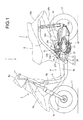
FIG. 1 is a side view of a motor scooter type motorcycle on which a power unit according to an embodiment of the present invention is mounted. -
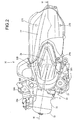
FIG. 2 is an appearance left side view of the power unit. -
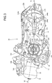
FIG. 3 is a left side view of the power unit from which a front-side side cover and a rear-side side cover constituting a left-side armor cover for the power unit have been detached. -
FIG. 4 is a left side view of the power unit from which a transmission case cover has further been detached -
FIG. 5 is a partly omitted right side view of the power unit from which a reduction gear cover has been detached. -
FIG. 6 is a developed sectional view taken along line VI-VI ofFIG. 2 . -
FIG. 7 is an enlarged view of a part ofFIG. 6 . -
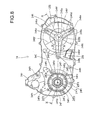
FIG. 8 is a left side view of the transmission case cover 24. -
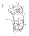
FIG. 9 is a right side view of the same. -
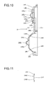
FIG. 10 is a sectional view taken along line X-X ofFIG. 8 . -
FIG. 11 is a sectional view taken along line XI-XI ofFIG. 8 . -
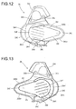
FIG. 12 is a left side view of a front-side side cover. -
FIG. 13 is a right side view of the same. -
FIG. 14 is a left side view of a rear-side side cover. -
FIG. 15 is a right side view of the same. -
FIG. 16 is a left side view showing the condition where the front-side side cover and the rear-side side cover are laid on each other at anextension part 26E and arecessed part 27D. -
FIG. 17 is a sectional view taken along line XVII-XVII ofFIG. 16 . -
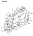
FIG. 18 is a perspective view of a substantially rear half part of the power unit. -
FIG. 1 is a side view of a motorscooter type motorcycle 1 on which apower unit 20 according to an embodiment of the present invention is mounted. - In the
motorcycle 1, a bodyfront part 2 and a bodyrear part 3 are connected to each other through alow floor part 4, and a body frame constituting the skeleton of the vehicle body is composed generally of a down tube 6 and main pipes 7. - More specifically, the down tube 6 extends downwards from a
head pipe 5 of thebody front part 2. The down tube 6 is bent at its lower end to be horizontal, and then extends rearwards on the lower side of thefloor part 4. A left-right pair of main pipes 7 are connected to each other at the rear end of the down tube 6, and the main pipes 7 rise from the connected part thereof toward an upper rear side, are then bent at a predetermined height to be horizontal, and extend rearwards. - A fuel tank and a luggage box are supported by the main pipes 7, and a seat 8 is disposed on the upper side thereof.
- On the other hand, on the side of the
body front part 2, asteering handle 11 is provided on the upper side while being rotatably supported by thehead pipe 5, afront fork 12 extends downwards, and afront wheel 13 is rotatably supported on the lower ends of thefront fork 12. -
Brackets 15 are projectingly provided near the centers of slant parts of the main pipes 7, and apower unit 20 is swingably and connectedly supported through alink member 16 rotatably supported on thebracket 15. - The
power unit 20 has a configuration in which aninternal combustion engine 30 is configured in a front part of aunit case 21, a belttype non-stage transmission 50 is disposed in the range from theinternal combustion engine 30 to the rear side, and areduction gear mechanism 110 is integrally provided at a rear part of thetransmission 50, with an output shaft of thereduction gear mechanism 110 forming arear axle 114 equipped with a rear wheel 17 (seeFIG. 2 ). - In the
power unit 20, a left-right pair ofpower unit hangers unit case 21, and thepower unit hangers link member 16 through apivot shaft 19; on the other hand, at a swingable rear part of theunit case 21, arear cushion 18 is interposed between abracket 29 at the rear end of the unit case 21 (transmission case 23) and the main pipe 7 (seeFIG. 1 ). - The
internal combustion engine 30 is a single-cylinder 4-stroke-cycle internal combustion engine, wherein acylinder block 31, acylinder head 32 and acylinder head cover 33 are projected from a front surface of theunit case 21 in a stacked manner and in a posture largely inclined forwards into a nearly horizontal state. - A
throttle body 34b is connected to anintake pipe 34a which is extended upwards from an intake port on the upper side in thecylinder head 32 and bent to the rear side. A connectingtube 34c extended rearwards from thethrottle body 34b is connected to anair cleaner 34d disposed at a rear half part of theunit case 21 along the left side of therear wheel 17. - In addition, an
exhaust pipe 35, which is extended downwards from an exhaust port on the lower side in thecylinder head 32 and bent to the rear side, extends rearwards in the state of being deviated to the right side, to be connected to a muffler (not shown) disposed on the right side of therear wheel 17. - The body
front part 2 is covered with a front cover 9a and arear cover 9b on the front and rear sides, and is covered with a frontlower cover 9c on the left and right sides. A central part of the steering handle 11 is covered with a handle cover 9d. - The
floor part 4 is covered with aside cover 9e, and the bodyrear part 3 is covered with abody cover 10a and tail side covers 10b on the left and right sides. -
FIG. 2 is a left side view showing the appearance of thepower unit 20;FIG. 3 is a left side view showing the condition where a front-side side cover 26 and a rear-side side cover 27 constituting a left-side armor cover of thepower unit 20 are detached;FIG. 4 is a left side view showing the condition where the transmission case cover 24 of thepower unit 20 is further detached; andFIG. 5 is a right side view showing the condition where areduction gear cover 25 is detached, with thepower unit 20 being partly omitted in the figure. -
FIG. 6 is a sectional view taken along line VI-VI ofFIG. 2 and developed, andFIG. 7 is an enlarged view of a part ofFIG. 6 . - Referring mainly to
FIG. 6 , theunit case 21 is split into left and right unit cases, and the left unit case is extended rearwards relative to theright unit case 22 so as to form atransmission case 23. - The
transmission case 23 is comprised of aleft crankcase part 23a formed on the right side of a front part, atransmission case part 23b formed on the left side over the range from the front part to a rear part, and areduction gear part 23c formed on the right side of the rear part. Theleft crankcase part 23a at the front part is mated with theright unit case 22 to form a crankchamber 40C for containing acrankshaft 40, while thetransmission case part 23b is covered with a transmission case cover 24 on the left side to form atransmission chamber 50C for containing a belttype non-stage transmission 50, and thereduction gear part 23c at the rear part is covered with areduction gear cover 25 to form areduction gear chamber 110C for containing thereduction gear mechanism 110. - In the
crank chamber 40C, acylinder sleeve 31s formed inside thecylinder block 31 is projected to the inside of thecrank chamber 40C, and the reciprocating motion of apiston 36 slidably fitted in thecylinder sleeve 31s is transmitted through a connectingrod 37 to thecrankshaft 40 rotatably borne on theunit case 21 while being oriented in the left-right horizontal direction, whereby thecrankshaft 40 is rotated. - An intake rocker arm 38bi and an exhaust rocker arm 38be are in swingable contact with a
cam shaft 38a of a valve-operatingmechanism 38 provided in thecylinder head 32 inclined forwards into a nearly horizontal state. An intake valve (not shown) and an exhaust valve (not shown) are driven by the intake rocker arm 38bi and the exhaust rocker arm 38be to open and close the relevant ports. - A
timing chain 38e is wrapped around a drivensprocket 38c attached to a right end part of thecam shaft 38a and a drivingsprocket 38d attached to thecrankshaft 40, and thecam shaft 38a is thereby rotated at a speed reduction ratio of 1/2 in relation to thecrankshaft 40. - In addition, the
cylinder head 32 is fitted with aspark plug 39p having an electrode exposed into acombustion chamber 39, which is defined by a ceiling surface faced by a top surface of thepiston 36. - In the
crank chamber 40C, a left-right pair of crankwebs crankshaft 40 is rotatably supported on left and right circular bearing holes of theunit case 21 through main bearings 41, 41. Of extension parts extending horizontally to the left and right sides, the right extension part is provided with anAC generator 42, whereas the left extension part is provided with adrive pulley 51 of the belttype non-stage transmission 50 together with atransmission driving mechanism 60. - The
AC generator 43 is covered with agenerator cover 28 on the right side. - Referring to
FIG. 7 , the left end of thecrankshaft 40 is rotatably supported through acollar 54 onto an annular bearing part 24Fa of the transmission case cover 24 through abearing 43. - A
drive pulley 51 is composed of a fixedpulley half 51s and amovable pulley half 51d. - A left extension part ranging from a
step part 40a reduced in diameter of thecrankshaft 40 is fitted with abearing 52, aguide sleeve 53, the fixedpulley half 51s and thecollar 54 in this order from the right side. An inner ring of thebearing 52, theguide sleeve 53, a base part of the fixedpulley half 51s, and thecollar 54 are fastened integrally to thecrankshaft 40, by fastening to the left end face of thecrankshaft 40 by abolt 56 through awasher 55. - Therefore, the fixed
pulley half 51s is fixed integrally with thecrankshaft 40 in the state of being clamped between theguide sleeve 53 and thecollar 54, and is rotated as one body with thecrankshaft 40. - Incidentally, a cooling
fan 51F is projectingly formed on the back surface (left side surface) of the fixedpulley half 51s. - On the other hand, the
movable pulley half 51d opposed to the fixedpulley half 51s from the right side has a configuration in which a cylindricalmovable pulley hub 51 dh as a base part thereof is partly spline-fitted to theguide sleeve 53 so that it is rotated as one body with thecrankshaft 40 and is slidable in the axial direction. - Thus, the
movable pulley half 51d disposed on the right side and facing the fixedpulley half 51s disposed on the left side is rotated together with thecrankshaft 40, and it can be slid in the axial direction toward and away from the fixedpulley half 51s. A V-belt 58 is clampedly wrapped between tapered surfaces of the pulley halves 51s, 51d. - Referring to
FIGS. 4 and6 , thetransmission case 23 is so formed that its part on the rear side of thepower unit hanger 21h of thetransmission case part 23b formed on the left side relative to theleft crankcase part 23a formed on the right side of a front part is largely bulging to the upper side, and a transmissionelectric motor 61 serving as a drive source of thetransmission driving mechanism 60 is attached to an upper part of the bulgingpart 23e from the right side. - A gear cover member (not shown) is partly attached to the bulging
part 23e of thetransmission case 23 from the left side, and a firstreduction gear shaft 63s and a second reduction gear shaft 65s are rotatably supported between the gear cover member and a wall surface of thetransmission case 23. Adrive gear 61a formed on adrive gear 61s of the transmissionelectric motor 61 is meshed with alarge diameter gear 63a on the firstreduction gear shaft 63s, and asmall diameter gear 63b on the firstreduction gear shaft 63s is meshed with alarge diameter gear 65a on the second reduction gear shaft 65s (seeFIG. 4 ). - On the other hand, a
female screw member 67 is attached by abolt 68 to adisk boss member 66 supported at its base end part on an outer ring of thebearing 52 fitted to thecrankshaft 40, a flange part of thefemale screw member 67 is formed with alarge diameter gear 67a, and thelarge diameter gear 67a is meshed with asmall diameter gear 65b on the second reduction gear shaft 65s. - A cylindrical part 67s of the
female screw member 67 is formed with a female screw (screw threads) at an inner peripheral surface thereof. - A
male screw member 70 is supported through abearing 69 fitted to the outer periphery of a movable pulley hub 51dh supporting themovable pulley half 51d and being slidable in the axial direction. Acylindrical part 70s of themale screw member 70 is located on the inside of a cylindrical part 67s of thefemale screw member 67, and a male screw formed at an outer peripheral surface of thecylindrical part 70s is meshed with the female screw formed at the inner peripheral surface of the cylindrical part 67s. - The
male screw member 70 is so disposed that the left end of thecylindrical part 70s thereof is exposed to the left side relative to the left opening end of the cylindrical part 67s of thefemale screw member 67, and theflange part 70a is exposed in a centrifugal direction along a back surface of themovable pulley half 51d from the left end. - An
annular member 71 is firmly attached to an outer peripheral part of theflange part 70a of themale screw member 70, a rear part of theannular member 71 extends rearwards and extends axially to the right side so as to come around to the outside of thelarge diameter part 67a of thefemale screw member 67, and theextension part 71a is clamped between an upper-lower pair ofguide pieces transmission chamber 50C, of thetransmission case 23, whereby rotation of theextension part 71a is restricted and axial movement of theextension part 71a is guided (seeFIG. 7 ). - Therefore, the
male screw member 70 supported through the bearing 69 onto the movable pulley hub 51dh integral with themovable pulley half 51d is restricted in rotation by theguide pieces - In the
transmission driving mechanism 60 configured as above, when the transmissionelectric motor 61 is driven and thedrive gear 61a formed on thedrive shaft 61s is rotated, thelarge diameter gear 63a of the firstreduction gear shaft 63s meshed with thedrive gear 61a is rotated together with thesmall diameter gear 63b with a speed reduction, thelarge diameter gear 65a on the second reduction gear shaft 65s meshed with thesmall diameter gear 63b is rotated together with thesmall diameter gear 65b with a further speed reduction, thelarge diameter gear 67a of thefemale screw member 67 meshed with thesmall diameter gear 65b is rotated with a further speed reduction, and thefemale screw member 67 is rotated. - When the
female screw member 67 is rotated, themale screw member 70 meshed therewith is moved in the axial direction by a screw mechanism, since it is restricted in rotation. - The axial movement of the
male screw member 70 causes an axial movement of the movable pulley hub 51dh as one body with themovable pulley half 51d through thebearing 69, whereby themovable pulley half 51d can be moved toward and away from the fixedpulley half 51s. - Incidentally, the
movable pulley half 51d is moved in the axial direction while being rotated together with thecrankshaft 40, since the movable pulley hub 51dh integrally supporting themovable pulley half 51d is spline fitted to theguide sleeve 53 integral with thecrankshaft 40. - With the
movable pulley half 51d thus moved toward and away from the fixedpulley half 51s by driving of the transmissionelectric motor 61 to rotate normally and reversely, the wrapping radius of the V-belt 58 wrapped between the opposed tapered surfaces of both the pulley halves 51 s, 51d is changed, whereby non-stage transmission is performed. - A
starter motor 75 is disposed in the state of being attached to theright crankcase 22, on the rear lower side of the transmissionelectric motor 61 mounted to the bulgingpart 23e of thetransmission case part 23b from the right side. - The
starter motor 75 is mounted, from the left side, to a left side surface of the bulging part 22e bulging slightly rearwards on the right side of theright crankcase 22, thestarter motor 75 being in such a posture as to have adrive shaft 75s set in the left-right direction in the same manner as and in parallel to that of the transmission electric motor 61 (seeFIG. 5 ). - Referring to
FIG. 5 , which is a right side view, a reduction gear shaft 76s is rotatably supported between thedrive shaft 75s of thestarter motor 75 and thecrankshaft 40, and alarge diameter gear 76a integral with the reduction gear shaft 76s is meshed with thedrive gear 75a formed on thedrive shaft 75s. - On the other hand, adjacently to the
AC generator 42 provided at the right end of thecrankshaft 40, a drivengear 77 is fittedly supported on arotary boss 78 rotatably supported on the crankshaft 40 (seeFIG. 6 ), and the drivengear 77 is meshed with asmall diameter gear 76b integral with the reduction gear shaft 76s. - Incidentally, a one-way clutch 79 is interposed between an outer rotor 42r, which is integral with the
crankshaft 40, of theAC generator 42 and therotary boss 78. - Therefore, when the
starter motor 75 is driven and thedrive gear 75a formed on thedrive shaft 75s is rotated, the large diameter gear 76s on the reduction gear shaft 76s which is meshed with thedrive gear 75a is rotated together with thesmall diameter gear 76b with speed reduction, the drivengear 77 meshed with thesmall diameter gear 76b is rotated together with therotary boss 78 with a further speed reduction, and the rotation of therotary boss 78 causes, through the one-way clutch 79, the outer rotor 42r of theAC generator 42 to rotate together with thecrankshaft 40, whereby starting of theinternal combustion engine 30 can be performed. - In addition, referring to
FIG. 5 , abalancer shaft 105 is rotatably supported on the upper side of thecrankshaft 40 so that abalancer weight 105w is rotated between the left and right crankwebs gear 104 fitted on thebalancer shaft 105 is meshed with abalancer drive gear 103 fitted on thecrankshaft 40. - Therefore, by the
balancer weight 105w rotated by and synchronously with the rotation of thecrankshaft 40, vibrations attendant on the operation of theinternal combustion engine 30 are suppressed. - Now, the structure of a rear part of the
power unit 20 will be described below. - Referring to
FIG. 6 , a drivenpulley 81 corresponding to the drivepulley 51 of the belttype non-stage transmission 50 is comprised of a fixedpulley half 81s and amovable pulley half 81d, which face each other and are both supported on a drivenshaft 82. - The driven
shaft 82 is rotatably supported on three portions, i.e., thetransmission case 23 and the transmission case cover 24 and thereduction gear cover 25 throughbearings - Referring to
FIG. 6 , a left side part of the drivenshaft 82 is formed with asmall diameter part 82a slightly reduced in outer diameter from a step part. Abearing 86, asupport sleeve 87 and acollar 88 are sequentially fitted on thesmall diameter part 82a, and anut 89 is screw engaged with an end part of thesmall diameter part 82a and is tightened to integrally fasten these components. - The
bearing 84 is interposed between an annular bearing part 24Ra of the transmission case cover 24 and thecollar 88. - A base part of a cup-shaped clutch outer 91 of a centrifugal clutch 90 is securely attached to the
support sleeve 87 so that the clutch outer 91 is rotated as one body with the drivenshaft 82. - On the outer periphery of a part, which is covered with the transmission case cover 24 on the right side of the clutch outer 91, of the driven
shaft 82, a cylindrical fixedpulley hub 95 supporting the fixedpulley half 81s is rotatably supported so that it can be rotated relatively to the drivenshaft 82 through the interposition of thebearing 86 and abearing 96 therebetween. - A
support plate 92a, which is the clutch inner 92 of the centrifugal clutch 90, is fixed to the left end of the fixedpulley hub 95 by anut 97. - A base end part of an
arm 92c is rotatably supported on apivotal shaft 92b of thesupport plate 92a, and aclutch shoe 92d is firmly attached to the tip of thearm 92c. - The
arm 92c is urged by aspring 92e in such a direction that theclutch shoe 92d is urged away from the inner peripheral surface of the clutch outer 91. - At the outer periphery of the cylindrical fixed
pulley hub 95 supporting the clutch inner 92, a cylindricalmovable pulley hub 98 supporting themovable pulley half 81d is provided so as to be slidable in the axial direction. - More specifically, the cylindrical
movable pulley hub 98 is provided with aguide hole 98a which is elongate along the axial direction, and aguide pin 99 projectingly provided on the fixedpulley hub 95 is slidably engaged with theguide hole 98a. - Therefore, the
movable pulley hub 98 is restricted in rotation relative to the fixedpulley hub 95 by theguide pin 99, and, at the same time, can slide in the axial direction on the fixedpulley hub 95 while being guided by theguide hole 98a. - A
coil spring 100 is interposed between thesupport plate 92a integrally attached to the fixedpulley hub 95 and themovable pulley hub 98, and themovable pulley hub 98 is urged rightwards by thecoil spring 100. - With the above configuration, the
movable pulley half 81 d supported on themovable pulley hub 98 is rotated together with the fixedpulley half 81s supported on the fixedpulley hub 95, is slidable in the axial direction, and is urged toward the fixedpulley half 81s by thecoil spring 100. - The V-
belt 58 is wrappted between the opposed tapered surfaces of the fixedpulley half 81s and themovable pulley hub 98, and the wrapping radius on the side of the drivenpulley 81 is changed in conjunction with the wrapping radius on the side of thedrive pulley 51 in a inverse proportional relationship, whereby non-stage transmission is performed. - When the rotating speed of the
drive pulley 51 exceeds a predetermined rotating speed, theclutch shoe 92d of the clutch inner 92 in the centrifugal clutch 90 comes into contact with the inner peripheral surface of the clutch outer 91 to rotate as one body with the latter, whereby motive power is transmitted to the drivenshaft 82. - On the right side of a rear part of the
transmission case 23, covering with thereduction gear cover 25 is conducted to form thereduction gear chamber 110C for containing thereduction gear mechanism 110. - As shown in
FIG. 4 , both ends of areduction gear shaft 112s is rotatably supported between a rear part of thetransmission case 23 and thereduction gear cover 25 which face each other, through bearings 111, 111, and alarge diameter gear 112a integral with thereduction gear shaft 112s is meshed with asmall diameter gear 82g formed on the drivengear 82. - Similarly, the
rear axle 114 is rotatably supported between a rear part of thetransmission case 23 and thereduction gear cover 25 throughbearings rear axle 114 protrudes rightward from the bearing 113 on the right side, and alarge diameter gear 114a integrally fitted on therear shaft 114 is meshed with asmall diameter gear 112b integral with thereduction gear shaft 112s. - The
rear wheel 17 is fitted on a part, protruding rearwards from thereduction gear cover 25, of therear axle 114. - Therefore, the rotation of the driven
shaft 82 is transmitted to therear wheel 17 with speed reduction through thereduction gear mechanism 110. - In the power transmission structure of the
power unit 20 as above-described, a configuration for introducing a cooling airflow into thetransmission chamber 50C defined by thetransmission case 23 and the transmission case cover 24 so as to cool the belttype non-stage transmission 50 is provided at a front part of the transmission case cover 24. - Of the transmission case cover 24, a left side view (outer side view) is shown in
FIG. 8 , a right side view (inner side view) is shown inFIG. 9 , a sectional view is shown inFIG. 10 , and a sectional view taken along line XI-XI ofFIG. 8 is shown inFIG. 11 . - Incidentally,
FIG. 18 showing a roughly rear half part of thepower unit 20 shows the transmission case cover 24 together with thetransmission case 23 in a perspective view. - Of the transmission case cover 24, a front part ranging from a mating surface 24s for mating to the
transmission case 23 is slightly bulging to the left side (outer side) in a roughly circular flat plate-like shape to form acircular wall part 24F, and a rear half part is bulging in a dome-like shape to form adome wall 24R (seeFIGS. 10 and18 ). - The
circular wall part 24F on the front side covers thedrive pulley 51, and thedome wall 24R on the rear side covers the centrifugal clutch 90 in a surrounding and containing manner. - Incidentally, the transmission case cover 24 is formed with a flat connecting
wall 24C (seeFIGS. 10 and18 ) between thecircular wall part 24F and thedome wall 24R both bulging to the outer side, and is formed, on the upper side of thecircular wall part 24F at a front part thereof, with abuilding part 24e correspondingly to thebuilding part 23e of thetransmission case 23. - The above-mentioned bearing part 24Fa for supporting the left end of the
crankshaft 40 through thebearing 43 is formed at a central part of thecircular wall part 24F, and the above-mentioned annular bearing part 24Ra for supporting the left end of the drivenshaft 82 through thebearing 84 is formed at an apex part of thedome wall 24R. - Of the annular bearing part 24Fa at a central part of the
circular wall part 24, an inner-side side wall is bulging to the axially outer side to form a small cup-shaped bulging wall 24Fb for covering an end of thecrankshaft 40, and a small diameter vent hole 24Rc is bored in the center of the bulging wall 24Rb. - The
circular wall part 24F at the outer periphery of the annular bearing part 24Fa on the front side is boredly provided with six sector-shaped cooling airflow inlet ports 24Fe, leaving six connecting ribs 24Fd in a radial pattern. - In other words, the annular bearing part 24Fa is supported by the six connecting ribs 24Fd.
- The cooling airflow inlet ports 24Fe formed at the outer periphery of the annular bearing part 24Fa are openings for introducing a cooling airflow into the
transmission chamber 50C. - Two of the six connecting ribs 24Fd are located on a straight line passing through the front and rear vent holes 24Fc, 24Rc in side view.
- In other words, the front and rear two connecting ribs 24Fd are formed on a plane S containing the
crankshaft 40, which is the drive shaft of the belttype non-stage transmission 50, and the driven shaft 82 (seeFIG. 3 ) - Therefore, it is possible to secure the rigidity in the front-rear direction of the transmission case cover 24, which receives a force generated due to turning of the V-
belt 58, and to reduce vibration. - Along the outer peripheral edges and the inner peripheral edges of the six sector-shaped cooling airflow inlet ports 24Fe, an outer ring projected part 24Ff and an inner ring projected part 24Fg both being annular are slightly projected to the left side.
- The outer ring projected part 24Ff and the inner ring projected part 24Fg are provided at the outer periphery of the bulging wall 24Fb.
- Four holder attaching bosses 24Fh for attaching a
filter holder 121 are formed at the outer periphery of the outer ring projected part 24Ff. - Incidentally, cover attaching bosses 24Fi are formed at a total of three positions, namely, upper front and rear two positions and one lower position, of the
circular wall part 24F. - On the other hand, the
dome wall 24R at the outer periphery of the annular bearing part 24Ra on the rear side is provided on a left side surface (outer side surface) thereof with three U-shaped outside ribs 24Rd extending in U shape radially from the annular bearing part 24Ra provided at the center. - Specifically, each of the U-shaped outside ribs 24Rd has a U shape in which a pair of substantially parallel side edges are extended in a centrifugal direction from the annular bearing part 24Ra, are curved at their tips, and the curved tips are connected to each other.
- The three U-shaped outside ribs 24Rd are at regular angular intervals, and base end parts of the adjacent U-shaped outside ribs 24Rd are connected to each other at the annular bearing part 24Ra.
- One of the U-shaped outside ribs 24Rd extends forwards from the annular bearing part 24Ra substantially in parallel to the straight line passing through the front and rear vent holes 24Fc and 24Rc in side view, and a curved part at its tip reaching the center of the transmission case cover 24 is formed with a cover attaching boss 24Rj for attaching the transmission case cover 24 to the transmission case 23 (see
FIG. 8 ). - The one pair of side edges of the U-shaped outside rib 24Rd extending forwards are so formed that they are substantially parallel to the plane S containing the drive shaft (crankshaft 40) of the belt
type non-stage transmission 50 and the drivenshaft 82 and are at substantially equal distances from the plane S, in side view shown inFIG. 3 . - Therefore, the rigidity in the front-rear direction of the
dome wall 24R of the transmission case cover 24 is particularly enhanced, whereby vibrations in the front-rear direction due to the turning of the V-belt 58 of the belttype non-stage transmission 50 can be suppressed more effectively. - The other two U-shaped outside ribs 24Rd extend from the annular bearing part 24Ra toward the rear upper side and the rear lower side at an angle of about 120 degrees in relation to the U-shaped outside rib 24Rd extending in the front-rear direction, and the curved tip parts of the outside ribs are formed with cover attaching bosses 24Ri, respectively.
- Therefore, the rigidity of the
dome wall 24R as a whole can be enhanced by a small number of ribs. - Incidentally, the connecting
wall 24C is formed with a cover attaching boss 24Ri at a position of a lower part thereof. - In addition, a right side surface (inner side surface) of the
dome wall 24R is formed with six inside ribs 24Rf extending radially from the annular bearing part 24Ra provided at the center. - The six inside ribs 24Rf are formed at regular angular intervals around the annular bearing part 24Ra, and, of them, the two inside ribs 24Rf extending in the front-rear direction are located on a straight line passing through the front and rear vent holes 24Fc and 24Rc in side view.
- Therefore, three of the six inside ribs 24Rf are substantially parallel to the three U-shaped outside ribs 24Rd on the outer side surface, respectively; in side view shown in
FIG. 8 , the inside ribs 24Rf are each located between the side edges ribs forming the U shape of the U-shaped outside rib 24Rd so as not to overlap with the latter. - Thus, the
dome wall 24R on the rear side of the transmission case cover 24 is provided on its outer side surface with the three U-shaped outside ribs projected and extending radially, and is provided on its inner side surface with the six inside ribs 24Rf projected and extending radially. Therefore, the rigidity of thedome wall 24R is remarkably enhanced by the synergistic effect of the U-shaped outside ribs 24Rd and the inside ribs 24Rf, so that vibrations of thedome wall 24R can be suppressed by a small number of simple ribs. - Incidentally, the
dome wall 24R of the transmission case cover 24 is provided with a coolingairflow outlet passage 24y in a lower part at the center in the front-rear direction, and is provided with a coolingairflow outlet passage 24z in a rear upper part. - The condition where the transmission case cover 24 as above is laid over the
transmission case 23 in the manner of covering the belttype non-stage transmission 50 is shown inFIG. 3 . - Of the
circular wall part 24F on the front side of the transmission case cover 24, an annular part which is provided with the six cooling airflow inlet ports 24Fe between the outer ring projected part 24Ff and the inner ring projected part 24Fg is fitted with a hollow circular disk-shapedfilter element 120, and thefilter element 120 is pressed by thefilter holder 121 from the outside, whereby thefilter element 120 is attached to the cooling airflow inlet ports 24Fe. - The
filter holder 121 is composed mainly of anouter ring part 121f and aninner ring part 121g fitted respectively to the outer ring projected part 24Ff and the inner ring projected part 24Fg of the transmission case cover 24, and six connectingribs 121d extending radially from theinner ring part 121g to be connected to theouter ring part 121f; in addition,bolt boss parts 121h are extended radially from four positions of theouter ring part 121f. - Of the
filter holder 121, the six connectingribs 121d are opposed to the six connecting ribs 24Fd of the transmission case cover 24; therefore, thefilter holder 121 is provided with coolingairflow inlet ports 121e correspondingly to the six sector-shaped cooling airflow inlet ports 24Fe of the transmission case cover 24. - In installing the
filter holder 121, theouter ring part 121f and theinner ring part 121g of thefilter holder 121 are fitted and connected respectively to the outer ring projected part 24Ff and the inner ring projected part 24Fg of the transmission case cover 24, the six connecting ribs 24Fd of thefilter holder 121 are pressed toward the six connecting ribs 24Fd of the transmission case cover 24 so as to clamp thefilter element 120 therebetween, and thebolt boss parts 121h are laid on the holder attaching bosses 24Fh at four positions of the outer periphery and are fastened in situ bybolts 122. - Thus, the six cooling
airflow inlet ports 121e of thefilter holder 121 and thefilter element 120 are disposed at the outer periphery of the bulging wall 24Fb bulging from the annular baring part 24Fa of the transmission case cover 24 so as to cover an end of thecrankshaft 40, and the six cooling airflow inlet ports 24Fe of the transmission case cover 24 are formed at the outer periphery of the annular bearing part 24Fa. The six cooling airflow inlet port 24Fe are located to face a coolingfan 51F provided on the back side of the fixedpulley half 51s fixed to thecrankshaft 40. - Therefore, under the action of the cooling
fan 51F rotated as one body with thecrankshaft 40, a cooling airflow from the outside of thefilter holder 121 flows sequentially through the coolingairflow inlet ports 121e, thefilter element 120 and the cooling airflow inlet ports 24Fe, and, in the filtered state, is introduced into thetransmission chamber 50C. - The inner-side side wall of the annular bearing part 24Fa, rotatably supporting an end part of the
crankshaft 40 through thebearing 43, of the transmission case cover 24 is bulging to the axially outer side to form the bulging wall 24Fb covering the end of thecrankshaft 40. By the bulging wall 24Fb, therefore, the cooling airflow taken in is straightened at the outer periphery of the bulging wall 24Fb and is smoothly guided into the cooling airflow inlet ports 24Fe at the outer periphery of the annular bearing part 24Fa, to be introduced into thetransmission chamber 50C, so that the quantity of the cooling air introduced into the belttype non-stage transmission 50 can be increased. - The cooling airflow introduced into the
transmission chamber 50C flows rearwards while cooling the belttype non-stage transmission 50, and is discharged through the coolingairflow outlet passage 24z at a rear part of the transmission case cover 24. - Of the transmission case cover 24, a substantially front half part is covered with the front-side side cover 26 on the lateral side, and a substantially rear half part is covered with a rear-side side cover 27 on the lateral side, so that the cooling
airflow inlet ports 121e, 24Fe are covered with the front-side side cover 26. - As shown in
FIGS. 12 and 13 , the front-side side cover 26 forms a front-side wall part 26F corresponding to thecircular wall part 24F of the transmission case cover 24, and forms on the upper side thereof abulging part 26e bulging correspondingly to the bulgingpart 24e of the transmission case cover 24; besides, anextension part 26E is formed which extends rearwards from the front-side wall part 26F at an acute angle while being gradually reduced in vertical width. - The front-
side wall part 26F has aperipheral wall 26C covering the transmission case cover 24 from the front side to the lower side of the latter (seeFIGS. 6 and7 ). - Upper and lower side edges 26Ee forming an acute angle of the
extension part 26E are slightly bent to the inner side (right side) until they intersect each other at their rear ends. - Front-
side cover ribs 26r are projectingly formed on the inner surface (right side surface) of theextension part 26E. - As shown in
FIG. 13 , the front-side cover ribs 26r are formed in a tapered form at an acute angle substantially in parallel to the upper and lower side edges 26Ee. - The upper and
lower cover ribs 26r formed in the tapered form constitutes an arcuate rib part 26rc which extends forwards to be connected to the inner surface of the front-side wall part 26F while forming a large circular arc. - Therefore, the front-
side cover ribs 26r form a single closed loop, and the rib arcuate part 26rc of the front-side wall part 26F is disposed at such a position as to surround the outer periphery of the annular outer ring projected part 24Ff, fitted with thefilter element 120 on the front side, of the transmission case cover 24. - In addition, on the inner surface of the front-
side wall part 26F of the front-side side cover 26, a second front-side cover rib 26rr is projectingly formed so as to further externally surround the rib arcuate part 26rc. Besides, in the inside of the rib arcuate part 26rc, five parallel rectilinear straightening ribs 26rl are projectingly formed in the state of extending slightly forwardly upwards rather than extending horizontally. - Incidentally, the front-side side cover 26 is formed with attaching
boss parts 26b at a total of three positions, upper front and rear portions and a lower portion of the front-side wall part 26F. - On the other hand, referring to
FIGS. 14, 15 and17 (and, further,FIG. 6 ), the rear-side side cover 27 covering a substantially rear half part of the transmission case cover 24 is composed of rearside wall parts 27R covering the connectingpart 24C and the rear-side dome wall 24R of the transmission case cover 24 on the lateral side, andperipheral walls 27C covering the connectingpart 24C and the rear-side dome wall 24R on the upper side through the rear side to the lower side. In addition, a central part in the vertical direction of a front part of the rearside wall parts 27R is formed with a recessedpart 27D recessed to the side of the connectingpart 24C of the transmission case cover 24. - The recessed
part 27D of the rear-side side cover 27 is so shaped that its bent edges 27De at the boundary of recessing from the rearside wall parts 27R have the same shapes (for overlapping) as the upper and lower side edges 26Ee of theextension part 26E, extending rearwards at an acute angle while being gradually reduced in vertical width, of the front-side side cover 26. - Therefore, the recessed
part 27D of the rear-side side cover 27 have its upper and lower bent edges 27De extending rearwards at an acute angle while being gradually reduced in vertical width, to intersect at their rear ends. - On an outer surface (left side surface) of a bottom wall 27Db of the recessed
part 27D, rear-side cover ribs 27r are projectingly formed. - As shown in
FIG. 14 , the rear-side cover ribs 27r are formed in a tapered overall shape at an acute angle, to be substantially parallel to the upper and lower bent edges 27De. - The upper and lower rear-
side cover ribs 27r formed in the tapered overall shape intersect at their rear ends, while their front ends protrude slightly forward beyond the front end of the rear-side wall part 27R while opening wider. - A rectangular parallelopiped
elastic body 125 is securely attached to the bottom wall 27Db in abutment, from the rear side, on the intersecting rear ends of the upper and lower rear-side cover ribs 27r. - In addition, on the inner surface (right side surface) of the rear-
side side cover 27, anopening support part 27p for supporting a tip opening part of a breather pipe is formed at a required position along the upper-sideperipheral wall 27C, in the shape of a trough which opens to the right side while having theperipheral wall 27C as a ceiling surface and which extends leftwards. - Incidentally, the rear-side side cover 27 is formed with attaching
boss parts 27b at a total of four positions, namely, at upper and lower positions of rear parts of the rearside wall parts 27R, at a lower position of the rear-side cover ribs 27r of front parts of the rearside wall parts 27R, and at abracket 27e extending slightly forwards beyond the front parts of the rearside wall parts 27R. - The rear-side side cover 27 is put on a side surface of a substantially half part of the transmission case cover 24, and the attaching
boss parts 27b at three portions consisting of upper and lower portions of a rear part and a front lower portion of the rear-side side cover 27 are fastened to cover attaching bosses 24Ri of the transmission case cover 24 bybolts 27B, whereby the rear-side side cover 27 is attached. Thereafter, the front-side side cover 26 is put on a side surface of a substantially front half part of transmission case cover 24, whereon therearward extension part 26E of the transmission case cover 24 is coveringly laid over the recessedpart 27D of the rear-side side cover 27, and, in this condition, the attachingboss parts 26b at three portions are fastened to cover attaching bosses 24Fi of the transmission case cover 24 bybolts 26B, whereby the front-side side cover 26 is attached (seeFIG. 2 ). - Incidentally, the attaching
boss part 26b at an upper rear portion of the front-side side cover 26 is co-fastened to the cover attaching boss 24Fi of the transmission case cover 24 by thebolt 26B, which is commonly used also for the attachingboss part 27b at an upper front portion of the rear-side side cover 27. - A side view of the condition where the front-
side side cover 26 and the rear-side side cover 27 are overlapping each other at theextension part 26E and the recessedpart 27D is shown inFIG. 16 , and a sectional view of an essential part thus overlapping is shown inFIG. 17 . - A cooling
airflow intake passage 126 is formed between therearward extension part 26E of the front-side side cover 26 and the recessedpart 27D of the rear-side side cover 27 overlapping therewith. - In the cooling
airflow intake passage 126, the tapered front-side cover ribs 26r of the front-side side cover 26 are located on the outside of and substantially in parallel to the tapered rear-side cover ribs 27r of the rear-side side cover 27. Therefore, the rear-side cover ribs 27r are surrounded by and on the inside of the front-side cover ribs 26r which form a closed loop together with the rib arcuate part 26rc (seeFIG. 16 ). - The connected part of the intersecting rear ends of the upper and lower front-
side cover ribs 26r formed in the tapered overall shape is abutted on theelastic body 125 secured to the recessed part bottom wall 27Db of the rear-side side cover 27, whereby the front-side cover ribs 26r are positioned at a predetermined distance from the recessed part bottom wall 27Db. Simultaneously, the upper and lower side edges 26Ee of theextension part 26E of the front-side side cover 26 are positioned so as to form coolingairflow intake gaps 127 between them and the upper and lower bent edges 27De constituting the recessedpart 27D of the rear-side side cover 27 (seeFIG. 17 ). - Similarly, the rear-
side cover ribs 27r are positioned at a predetermined distance from theextension part 26E of the front-side side cover 26 (seeFIG. 17 ). - Therefore, the cooling
airflow intake gaps 127 are elongately formed along the upper and lower side edges 26Ee extended in a tapered overall shape at an acute angle toward the rear side of theextension part 26E of the front-side side cover 26, and the cooling airflows are taken in through the coolingairflow intake gaps 127 into the coolingairflow intake passage 126 as indicated by broken lines inFIG. 17 . - The front-
side cover ribs 26r and the rear-side cover ribs 27r are projected into the coolingairflow intake passage 126 to form a labyrinth, so that the cooling airflows taken in through the coolingairflow intake gaps 127 can pass smoothly through the coolingairflow intake passage 126 while being each guided sequentially by the front-side cover rib 26r and the rear-side cover rib 27r. - In this manner, the cooling airflows being guided through the cooling
airflow intake passage 126 by the front-side cover ribs 26r and the rear-side cover ribs 27r flow forwards through the inside of the front-side side cover 26 while being straightened by the straightening ribs 26rl, to reach the lateral sides of thefilter element 120 disposed at the cooling airflow inlet ports 24Fe of the transmission case cover 24. Therefore, the cooling airflows are permitted to flow efficiently through thefilter element 120, to be introduced through the cooling airflow inlet ports 24Fe into thetransmission chamber 50C. - The cooling airflow introduced into the
transmission chamber 50C flows rearwards while cooling the belttype non-stage transmission 50, and is discharged through the coolingairflow outlet passage 24y at a central lower part of the transmission case cover 24 and the coolingairflow outlet passage 24z on the rear side thereof. - Thus, the recessed
part 27D recessed to the side of the transmission case cover 24 is formed at a front part of the rear-side side cover 27, theextension part 26E extended rearwards in a tapered form at a rear part of the front-side side cover 26 is coveringly laid over the recessedpart 27D externally, the coolingairflow intake gaps 127 are formed along the side edges 26Ee of theextension part 26E between the side edges 26Ee and the bent edges 27De of the rear-side side cover 27, and the coolingairflow intake passage 126 is formed between theextension part 26E and the recessedpart 27D, so that the coolingairflow intake passage 126 can be formed without making the front-side side cover 26 to have a box cover shape. Therefore, the front-side side cover 26 is not projectingly provided on the transmission case cover 24, thepower unit 20 can be suppressed in left-right width (width in the crankshaft direction), and thepower unit 20 can be restrained from being enlarged in size. - The
extension part 26E of the front-side side cover 26 is substantially flat plate-like in shape, and is coveringly laid on the recessedpart 27D of the rear-side side cover 27, to form thecooling airflow gaps 127 between the side edges 26Ee of theextension part 26E and the bent edges 27De of the recessedpart 27D. As shown inFIG. 17 , therefore, the outside surface of theextension part 26E and the outside surface of the rearside wall parts 27R in the periphery of the recessedpart 27D of the rear-side side cover 27 are substantially flush with each other, and no large undulation is present at the boundary between the two members, so that a feeling of unity of thepower unit 20 as a whole in appearance can be easily obtained, and the appearance can be improved. - Into the cooling
airflow intake passage 126 formed between theextension part 26E of the front-side side cover 26 and the recessedpart 27D of the rear-side side cover 27, the front-side cover ribs 26r and the rear-side cover ribs 27r are projected substantially in parallel to the side edges 26Ee of theextension part 26E. Therefore, the cooling airflows taken in through the coolingairflow intake gaps 127 formed along the side edges 26Ee of theextension part 26E passes through the labyrinth defined by the front-side cover ribs 26r and the rear-side cover ribs 27r in the coolingairflow intake passage 126, whereby it is possible to prevent muddy water or foreign matter from penetrating to the depth relative to the coolingairflow intake passage 126. - The front-
side cover ribs 26r are provided between the side edges 26Ee of theextension part 26E and the rear-side cover ribs 27r. Therefore, the cooling airflows taken in through the coolingairflow intake gaps 127 are each guided sequentially by the front-side cover rib 26r and the rear-side cover rib 27r, as indicated by broken lines inFIG. 17 . Accordingly, the flow passage does not include any blind alley, so that the cooling airflows can pass smoothly through the coolingairflow intake passage 126 without stagnating, whereby the quantity of the cooling air taken in can be increased. - Since the
extension part 26E of the front-side side cover 26 is extended rearwards in a tapered shape at an acute angle while being gradually decreased in vertical width, the coolingairflow intake gaps 127 formed along the upper and lower side edges 26Ee of theextension part 26E are also formed in a tapered shape while being bent at an acute angle. Therefore, with the side cover restricted in vertical width, the distance of the coolingairflow intake gaps 127 can be secured to be large, whereby the quantity of cooling air taken in can be increased, and the cooling capability can be enhanced thereby. - The
filter element 120 is interposed at the cooling airflow inlet ports 24Fe of the transmission case cover 24, and the front-side cover ribs 26r are extended forwards and formed with the rib arcuate part 26rc so as to surround the outer periphery of thefilter element 120. Therefore, the cooling airflows entering the inside of the front-side cover ribs 26r constituting a closed loop can be efficiently guided into thefilter element 120 and be introduced into thetransmission chamber 40C through thefilter element 120, whereby the efficiency of cooling the belttype non-stage transmission 50 can be enhanced. - Since the second front-side cover ribs 26rr are formed so as to further externally surround the rib arcuate part 26rc, surrounding the outer periphery of the
filter element 120, of the front-side cover ribs 26r, the noise leaking to the exterior through the cooling airflow passage can be reduced by the double structure of the ribs 26rc and 26rr. - In the above-described embodiment, a structure has been adopted in which the
extension part 26E of the front-side side cover 26 is substantially flat plate-like in shape and is coveringly stacked on the recessedpart 27D of the rear-side side cover 27. However, a structure may be adopted in which a recessed part recessed to the transmission case cover side is formed at a rear part of the front-side side cover, an extension part extending forwards is formed at a front part of the rear-side side cover, and the extension part of the rear-side side cover is coveringly put on the recessed part of the front-side side cover from the outer side. With the cooling airflow intake gaps formed between the side edges of the extension part and the rear-side side cover and with the cooling airflow intake passage formed between the extension part and the recessed part, the power unit can be restrained from being enlarged in size, without projecting the rear-side side cover on the transmission case cover and while suppressing the width of the power unit in the crankshaft direction. In addition, undulation at the boundary of the rear-side side cover relative to the transmission case cover is reduced, whereby a feeling of unity of the power unit as a whole can be easily obtained, and the appearance can be improved. -
- 20 power unit, 21 unit case, 22 right unit case, 23 transmission case, 24 transmission case cover, 24Fa annular bearing part, 24Fb bulging wall, 24Fd connecting rib, 24Fe cooling airflow inlet port, 24R dome wall, 24z cooling airflow inlet passage,
- 26 front-side side cover, 26F front-side wall part, 26E extension part, 26r front-side cover rib, 26rc rib arcuate part, 26rr second front-side cover rib;
- 27 rear-side side cover, 27R rear side wall part, 27D recessed part, 27r rear-side cover rib,
- 30 internal combustion engine, 40 crankshaft, 50 belt type non-stage transmission, 50C transmission chamber, 51 drive pulley, 51F cooling fan,
- 120 filter element, 121 filter holder, 126 cooling airflow inlet passage, 127 cooling airflow intake gap.
Claims (7)
- A cooling structure for a belt type non-stage transmission (50) in a power unit (20) mounted on a motorcycle (1), said belt type non-stage transmission (50) being provided on a lateral side of a transmission case (23) serving also as a crankcase for rotatably supporting a crankshaft (40) of an internal combustion engine (30), a transmission case cover (24) being disposed on said transmission case (23) from a lateral side so as to cover said belt type non-stage transmission (50) and to form a transmission chamber (50C),
wherein a drive pulley (51) including a movable pulley half (51d) and a fixed pulley half (51s) provided at said crankshaft (40) of said belt type non-stage transmission (50) is provided with a cooling fan (51F) at said fixed pulley half (51s) on the transmission case cover side;
said transmission case cover (24) is provided with a cooling airflow inlet port (24Fe) for introducing a cooling airflow into said transmission chamber (50C), at its part to which said cooling fan (51F) is opposed;
a substantially front half part of said transmission case cover (24) is covered with a front-side side cover (26) from a lateral side, and a substantially rear half part of said transmission case cover (24) is covered with a rear-side side cover (27) from a lateral side;
said rear-side side cover (27) is provided in a front part thereof with a recessed part (27D) which is recessed toward the transmission case cover side;
said front-side side cover (26) is provided at a rear part thereof with an extension part (26E) extended rearwards; and
said extension part (26E) of said front-side side cover (26) is coveringly disposed on said recessed part (27D) of said rear-side side cover (27) from an outer lateral side, whereby a cooling airflow intake gap (127) is formed between said extension part (26E) and said rear-side side cover (27) along a side edge of said extension part (26E), and a cooling airflow intake passage (126) is formed between said extension part (26E) and said recessed part (27D). - The cooling structure for the belt type non-stage transmission as set forth in claim 1, wherein said cooling airflow intake passage (126) is provided with a front-side cover rib (26r) projecting from said extension part (26E) toward a bottom wall of said recessed part (27D) of said rear-side side cover (27), substantially in parallel to a side edge of said extension part (26E) of said front-side side cover (26), and is provided with a rear-side cover rib (27r) projecting in parallel to said front-side cover rib (26r) from said bottom wall of said recessed part (27D) toward said extension part (26E).
- The cooling structure for the belt type non-stage transmission as set forth in claim 2, wherein said front-side cover rib (26r) is provided between a side edge of said extension part (26E) and said rear-side cover rib (27r).
- The cooling structure for the belt type non-stage transmission as set forth in claim 2 or 3, wherein said extension part (26E) of said front-side side cover (26) is extended rearwards while being tapered at an acute angle and with its vertical width gradually decreased.
- The cooling structure for the belt type non-stage transmission as set forth in any one of claims 2 to 4, wherein a filter element (120) is interposed at said cooling airflow inlet port (24Fe) of said transmission case cover (24), and
said front-side cover rib (26r) is formed with a rib arcuate part (26rc) extending forwards so as to surround the outer periphery of said filter element (120). - The cooling structure for the belt type non-stage transmission as set forth in claim 5, wherein a second front-side cover rib (26rr) is formed so as to surround further externally said rib arcuate part (26rc), surrounding the outer periphery of said filter element (120), of said front-side cover rib (26r).
- A cooling structure for a belt type non-stage transmission (50) in a power unit (20) mounted on a motorcycle (1), said belt type non-stage transmission (50) being provided on a lateral side of a transmission case (23) serving also as a crankcase for rotatably supporting a crankshaft (40) of an internal combustion engine (30), a transmission case cover (24) being disposed on said transmission case (23) from a lateral side so as to cover said belt type non-stage transmission (50) and to form a transmission chamber (50C),
wherein a drive pulley (51) including a movable pulley half and a fixed pulley half provided at said crankshaft (40) of said belt type non-stage transmission (50) is provided with a cooling fan (51F) at said fixed pulley half on the transmission case cover side;
said transmission case cover (24) is provided with a cooling airflow inlet port (24Fe) for introducing a cooling airflow into said transmission chamber (50C), at its part to which said cooling fan (51F) is opposed;
a substantially front half part of said transmission case cover (26) is covered with a front-side side cover from a lateral side, and a substantially rear half part of said transmission case cover is covered with a rear-side side cover (27) from a lateral side;
said front-side side cover (26) is provided in a rear part thereof with a recessed part which is recessed toward the transmission case cover side;
said rear-side side cover (27) is provided at a front part thereof with an extension part extended forwards; and
said extension part (26E) of said rear-side side cover (27) is coveringly disposed on said recessed part of said front-side side cover (26) from an outer lateral side, whereby a cooling airflow intake gap (127) is formed between said extension part (26E) and said front-side side cover (27) along a side edge of said extension part (26E), and a cooling airflow intake passage (126) is formed between said extension part (26E) and said recessed part.
Applications Claiming Priority (1)
| Application Number | Priority Date | Filing Date | Title |
|---|---|---|---|
| JP2007194963A JP4891172B2 (en) | 2007-07-26 | 2007-07-26 | Cooling structure for belt type continuously variable transmission. |
Publications (3)
| Publication Number | Publication Date |
|---|---|
| EP2020536A2 true EP2020536A2 (en) | 2009-02-04 |
| EP2020536A3 EP2020536A3 (en) | 2009-09-16 |
| EP2020536B1 EP2020536B1 (en) | 2011-08-31 |
Family
ID=39967196
Family Applications (1)
| Application Number | Title | Priority Date | Filing Date |
|---|---|---|---|
| EP08160937A Expired - Fee Related EP2020536B1 (en) | 2007-07-26 | 2008-07-23 | Power unit for a motorcycle |
Country Status (3)
| Country | Link |
|---|---|
| EP (1) | EP2020536B1 (en) |
| JP (1) | JP4891172B2 (en) |
| ES (1) | ES2370559T3 (en) |
Cited By (4)
| Publication number | Priority date | Publication date | Assignee | Title |
|---|---|---|---|---|
| WO2014154316A1 (en) * | 2013-03-28 | 2014-10-02 | Sew-Eurodrive Gmbh & Co. Kg | Gearbox with a shaft |
| EP2827024A1 (en) * | 2013-07-18 | 2015-01-21 | Kwang Yang Motor Co., Ltd. | Cooling airflow guide structure of vehicle transmission box |
| CN107567553A (en) * | 2015-04-16 | 2018-01-09 | 比亚乔及C.股份公司 | Lid structure for the transmission device of motorcycle |
| EP3438508A4 (en) * | 2016-03-30 | 2019-03-20 | Honda Motor Co., Ltd. | Transmission case structure for saddle-type vehicle power unit |
Families Citing this family (2)
| Publication number | Priority date | Publication date | Assignee | Title |
|---|---|---|---|---|
| JP5847654B2 (en) * | 2012-06-13 | 2016-01-27 | 本田技研工業株式会社 | Transmission case structure in a power unit for saddle-ride type vehicles |
| EP3085997B1 (en) | 2015-04-23 | 2020-07-22 | Flender GmbH | Air guidance hood for a gearbox and gearbox with an air guidance hood |
Citations (1)
| Publication number | Priority date | Publication date | Assignee | Title |
|---|---|---|---|---|
| JP2001065672A (en) | 1999-08-31 | 2001-03-16 | Yamaha Motor Co Ltd | V-belt type automatic transmission for vehicle |
Family Cites Families (1)
| Publication number | Priority date | Publication date | Assignee | Title |
|---|---|---|---|---|
| JP4523323B2 (en) * | 2004-04-20 | 2010-08-11 | 本田技研工業株式会社 | Soundproof structure in power unit |
-
2007
- 2007-07-26 JP JP2007194963A patent/JP4891172B2/en not_active Expired - Fee Related
-
2008
- 2008-07-23 EP EP08160937A patent/EP2020536B1/en not_active Expired - Fee Related
- 2008-07-23 ES ES08160937T patent/ES2370559T3/en active Active
Patent Citations (1)
| Publication number | Priority date | Publication date | Assignee | Title |
|---|---|---|---|---|
| JP2001065672A (en) | 1999-08-31 | 2001-03-16 | Yamaha Motor Co Ltd | V-belt type automatic transmission for vehicle |
Cited By (10)
| Publication number | Priority date | Publication date | Assignee | Title |
|---|---|---|---|---|
| WO2014154316A1 (en) * | 2013-03-28 | 2014-10-02 | Sew-Eurodrive Gmbh & Co. Kg | Gearbox with a shaft |
| US10718353B2 (en) | 2013-03-28 | 2020-07-21 | Sew-Eurodrive Gmbh & Co.Kg | Gearbox with a shaft |
| EP2827024A1 (en) * | 2013-07-18 | 2015-01-21 | Kwang Yang Motor Co., Ltd. | Cooling airflow guide structure of vehicle transmission box |
| TWI513608B (en) * | 2013-07-18 | 2015-12-21 | Kwang Yang Motor Co | The wind - driven structure of the cooling wind of the vehicle transmission box |
| CN107567553A (en) * | 2015-04-16 | 2018-01-09 | 比亚乔及C.股份公司 | Lid structure for the transmission device of motorcycle |
| US20180119793A1 (en) * | 2015-04-16 | 2018-05-03 | Piaggio & C. S.P.A | Cover structure for the transmission of a motorcycle |
| US10502310B2 (en) * | 2015-04-16 | 2019-12-10 | Piaggio & C. S.P.A. | Cover structure for the transmission of a motorcycle |
| TWI695943B (en) * | 2015-04-16 | 2020-06-11 | 義大利商比雅久股份有限公司 | Cover structure for the transmission of a motorcycle |
| CN107567553B (en) * | 2015-04-16 | 2020-10-27 | 比亚乔及C.股份公司 | Cover structure for transmission of motorcycle |
| EP3438508A4 (en) * | 2016-03-30 | 2019-03-20 | Honda Motor Co., Ltd. | Transmission case structure for saddle-type vehicle power unit |
Also Published As
| Publication number | Publication date |
|---|---|
| JP2009030714A (en) | 2009-02-12 |
| ES2370559T3 (en) | 2011-12-20 |
| EP2020536B1 (en) | 2011-08-31 |
| EP2020536A3 (en) | 2009-09-16 |
| JP4891172B2 (en) | 2012-03-07 |
Similar Documents
| Publication | Publication Date | Title |
|---|---|---|
| EP2019233B1 (en) | Power unit | |
| US6544134B2 (en) | Belt type transmission | |
| EP2474435B1 (en) | Cooling air intake structure for v-belt type stepless transmission | |
| EP2020536B1 (en) | Power unit for a motorcycle | |
| JP4384457B2 (en) | engine | |
| US6357545B1 (en) | Power unit for vehicle | |
| EP2020534B1 (en) | Power unit | |
| JP3891756B2 (en) | Lubrication structure of internal combustion engine | |
| CN107848411B (en) | Power unit for saddle-ride type vehicle | |
| KR101063066B1 (en) | Cooling structure of belt type continuously variable transmission | |
| JP5022355B2 (en) | Water pump mounting structure for water-cooled internal combustion engine | |
| JP4420292B2 (en) | Saddle-type vehicle engine and straddle-type vehicle equipped with the same | |
| JP2010101301A (en) | Cam chain tensioner pivot mounting structure of internal combustion engine | |
| JP4975547B2 (en) | Power unit transmission case cover | |
| JP5189008B2 (en) | Crankcase structure of internal combustion engine | |
| JP2011047334A (en) | Cooling device for power unit | |
| EP1840417B1 (en) | Power Unit | |
| CN100486861C (en) | Riding type vehicle | |
| JP4425646B2 (en) | Auxiliary structure for internal combustion engine | |
| JP5227922B2 (en) | Torque damper device for saddle-ride type vehicles | |
| JP2009029253A (en) | Breather structure of deceleration chamber of power unit | |
| CN100484822C (en) | Saddle-type vehicle | |
| JP6788534B2 (en) | Internal combustion engine crankshaft structure | |
| JP6771922B2 (en) | Power unit for saddle-mounted vehicles with kick starter | |
| JP5268746B2 (en) | Pulley structure of V-belt continuously variable transmission |
Legal Events
| Date | Code | Title | Description |
|---|---|---|---|
| PUAI | Public reference made under article 153(3) epc to a published international application that has entered the european phase |
Free format text: ORIGINAL CODE: 0009012 |
|
| AK | Designated contracting states |
Kind code of ref document: A2 Designated state(s): AT BE BG CH CY CZ DE DK EE ES FI FR GB GR HR HU IE IS IT LI LT LU LV MC MT NL NO PL PT RO SE SI SK TR |
|
| AX | Request for extension of the european patent |
Extension state: AL BA MK RS |
|
| PUAL | Search report despatched |
Free format text: ORIGINAL CODE: 0009013 |
|
| AK | Designated contracting states |
Kind code of ref document: A3 Designated state(s): AT BE BG CH CY CZ DE DK EE ES FI FR GB GR HR HU IE IS IT LI LT LU LV MC MT NL NO PL PT RO SE SI SK TR |
|
| AX | Request for extension of the european patent |
Extension state: AL BA MK RS |
|
| 17P | Request for examination filed |
Effective date: 20100311 |
|
| AKX | Designation fees paid |
Designated state(s): DE ES FR IT |
|
| 17Q | First examination report despatched |
Effective date: 20100528 |
|
| GRAP | Despatch of communication of intention to grant a patent |
Free format text: ORIGINAL CODE: EPIDOSNIGR1 |
|
| RTI1 | Title (correction) |
Free format text: POWER UNIT FOR A MOTORCYCLE |
|
| GRAS | Grant fee paid |
Free format text: ORIGINAL CODE: EPIDOSNIGR3 |
|
| GRAA | (expected) grant |
Free format text: ORIGINAL CODE: 0009210 |
|
| AK | Designated contracting states |
Kind code of ref document: B1 Designated state(s): DE ES FR IT |
|
| REG | Reference to a national code |
Ref country code: DE Ref legal event code: R096 Ref document number: 602008009251 Country of ref document: DE Effective date: 20111110 |
|
| REG | Reference to a national code |
Ref country code: ES Ref legal event code: FG2A Ref document number: 2370559 Country of ref document: ES Kind code of ref document: T3 Effective date: 20111220 |
|
| PLBE | No opposition filed within time limit |
Free format text: ORIGINAL CODE: 0009261 |
|
| STAA | Information on the status of an ep patent application or granted ep patent |
Free format text: STATUS: NO OPPOSITION FILED WITHIN TIME LIMIT |
|
| 26N | No opposition filed |
Effective date: 20120601 |
|
| REG | Reference to a national code |
Ref country code: DE Ref legal event code: R097 Ref document number: 602008009251 Country of ref document: DE Effective date: 20120601 |
|
| PGFP | Annual fee paid to national office [announced via postgrant information from national office to epo] |
Ref country code: DE Payment date: 20150714 Year of fee payment: 8 |
|
| REG | Reference to a national code |
Ref country code: FR Ref legal event code: PLFP Year of fee payment: 9 |
|
| REG | Reference to a national code |
Ref country code: DE Ref legal event code: R119 Ref document number: 602008009251 Country of ref document: DE |
|
| PG25 | Lapsed in a contracting state [announced via postgrant information from national office to epo] |
Ref country code: DE Free format text: LAPSE BECAUSE OF NON-PAYMENT OF DUE FEES Effective date: 20170201 |
|
| REG | Reference to a national code |
Ref country code: FR Ref legal event code: PLFP Year of fee payment: 10 |
|
| PGFP | Annual fee paid to national office [announced via postgrant information from national office to epo] |
Ref country code: FR Payment date: 20170613 Year of fee payment: 10 |
|
| PGFP | Annual fee paid to national office [announced via postgrant information from national office to epo] |
Ref country code: BE Payment date: 20170627 Year of fee payment: 16 |
|
| PG25 | Lapsed in a contracting state [announced via postgrant information from national office to epo] |
Ref country code: FR Free format text: LAPSE BECAUSE OF NON-PAYMENT OF DUE FEES Effective date: 20180731 |
|
| REG | Reference to a national code |
Ref country code: ES Ref legal event code: FD2A Effective date: 20190917 |
|
| PG25 | Lapsed in a contracting state [announced via postgrant information from national office to epo] |
Ref country code: ES Free format text: LAPSE BECAUSE OF NON-PAYMENT OF DUE FEES Effective date: 20180724 |
|
| PGFP | Annual fee paid to national office [announced via postgrant information from national office to epo] |
Ref country code: IT Payment date: 20190719 Year of fee payment: 12 |
|
| PG25 | Lapsed in a contracting state [announced via postgrant information from national office to epo] |
Ref country code: IT Free format text: LAPSE BECAUSE OF NON-PAYMENT OF DUE FEES Effective date: 20200723 |