EP2020510A2 - Druckleitung zur fluidischen Verbindung einer Pumpe zu einem hydraulischen Stellaggregat in einem Kraftfahrzeug - Google Patents
Druckleitung zur fluidischen Verbindung einer Pumpe zu einem hydraulischen Stellaggregat in einem Kraftfahrzeug Download PDFInfo
- Publication number
- EP2020510A2 EP2020510A2 EP08010427A EP08010427A EP2020510A2 EP 2020510 A2 EP2020510 A2 EP 2020510A2 EP 08010427 A EP08010427 A EP 08010427A EP 08010427 A EP08010427 A EP 08010427A EP 2020510 A2 EP2020510 A2 EP 2020510A2
- Authority
- EP
- European Patent Office
- Prior art keywords
- hydraulic
- lines
- arrangement according
- line
- pump
- Prior art date
- Legal status (The legal status is an assumption and is not a legal conclusion. Google has not performed a legal analysis and makes no representation as to the accuracy of the status listed.)
- Granted
Links
- 239000012530 fluid Substances 0.000 title claims abstract 3
- 239000012528 membrane Substances 0.000 claims abstract description 8
- 239000000463 material Substances 0.000 claims description 6
- 230000010355 oscillation Effects 0.000 description 6
- 238000002485 combustion reaction Methods 0.000 description 5
- 230000005284 excitation Effects 0.000 description 2
- 230000001133 acceleration Effects 0.000 description 1
- 230000002411 adverse Effects 0.000 description 1
- 230000002238 attenuated effect Effects 0.000 description 1
- 230000005540 biological transmission Effects 0.000 description 1
- 238000013016 damping Methods 0.000 description 1
- 230000002269 spontaneous effect Effects 0.000 description 1
Images

Classifications
-
- F—MECHANICAL ENGINEERING; LIGHTING; HEATING; WEAPONS; BLASTING
- F15—FLUID-PRESSURE ACTUATORS; HYDRAULICS OR PNEUMATICS IN GENERAL
- F15B—SYSTEMS ACTING BY MEANS OF FLUIDS IN GENERAL; FLUID-PRESSURE ACTUATORS, e.g. SERVOMOTORS; DETAILS OF FLUID-PRESSURE SYSTEMS, NOT OTHERWISE PROVIDED FOR
- F15B1/00—Installations or systems with accumulators; Supply reservoir or sump assemblies
- F15B1/02—Installations or systems with accumulators
- F15B1/021—Installations or systems with accumulators used for damping
-
- B—PERFORMING OPERATIONS; TRANSPORTING
- B62—LAND VEHICLES FOR TRAVELLING OTHERWISE THAN ON RAILS
- B62D—MOTOR VEHICLES; TRAILERS
- B62D5/00—Power-assisted or power-driven steering
- B62D5/06—Power-assisted or power-driven steering fluid, i.e. using a pressurised fluid for most or all the force required for steering a vehicle
- B62D5/062—Details, component parts
-
- F—MECHANICAL ENGINEERING; LIGHTING; HEATING; WEAPONS; BLASTING
- F15—FLUID-PRESSURE ACTUATORS; HYDRAULICS OR PNEUMATICS IN GENERAL
- F15B—SYSTEMS ACTING BY MEANS OF FLUIDS IN GENERAL; FLUID-PRESSURE ACTUATORS, e.g. SERVOMOTORS; DETAILS OF FLUID-PRESSURE SYSTEMS, NOT OTHERWISE PROVIDED FOR
- F15B21/00—Common features of fluid actuator systems; Fluid-pressure actuator systems or details thereof, not covered by any other group of this subclass
- F15B21/008—Reduction of noise or vibration
Definitions
- vibrations are introduced into the hydraulic circuit via the hydraulic pump from the internal combustion engine of the vehicle.
- a torsional vibration On the speed of the internal combustion engine is a torsional vibration, which affects the size of the amplitudes and phases of the torsional vibration to a large extent.
- the torsional vibration is caused by the permanent acceleration and the deceleration of the crankshaft with each piston stroke. Further influences come from the hydraulic system itself.
- the vibrations described above are converted in idle mode directly from the hydraulic pump into hydraulic vibrations and introduced into the hydraulic system.
- These indirectly generated noise from the drive train of the vehicle are introduced into the steering system, which is to be regarded as an amplifier and transmitter of the noise in the passenger compartment.
- the steering feel is adversely affected because in spontaneous steering maneuvers also a part of the energy is absorbed.
- the lines have a different duration for sound, pressure and volume waves, in particular different line length .DELTA.l, with suitable tuning, the waves may be due to interference extinguish.
- the volume flow through one of the parallel lines can be prevented if in this line an internal device is provided, which has a line dividing the line into two separate volumes vibratable membrane.
- a particularly advantageous embodiment of the invention is to be considered when the inner device for receiving the membrane is located between the parallel hydraulic lines.
- the inner device for receiving the membrane can be integrated between the branches in the hydraulic line.
- the conduit arrangement with the pressure lines and the inner device for receiving the membrane can be integrated with the external device, so that the assembly is simplified and this device can be supplied as a single component.
- Another particularly advantageous embodiment is when the external device comprising the conduit arrangement is an oil cooler.
- the function can be positively influenced if the hydraulic lines have suitable differences in material and surface finish.
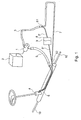
- Fig.1 is a hydraulic power steering known per se shown schematically.
- the steering comprises a hydraulic pump 1, which is driven by an internal combustion engine 2.
- the pump 1 is connected via a first hydraulic line 3 to the input of a servo valve 4 and a second hydraulic line 5 to the return of the servo valve 1.
- the servo valve 4 is connected in a known manner with the working spaces of the actuator 6.
- the actuator operates in a conventional manner, the tie rods 10th
- the first hydraulic line 3 is connected to a third hydraulic line 7 at a point s1.
- the first hydraulic line 3 is connected to an inner device 8.
- the inner device 8 is connected to the second part of the first hydraulic line 3.
- the third hydraulic line 7 is connected at a point s2 to the first hydraulic line.
- the inner device 8 is equipped with a membrane 9.
- ⁇ / 2 represents the required pipe length of the third hydraulic line.
- FIG. 3 shows the pressure wave / volume flow wave v coming from the pump.
- the pressure wave flows into the first and third hydraulic lines 3, 7, in which the shaft V continues in two waves V1, V2 of different phase.
- the waves V1, V2 meet with different phases.
- the point s1 connects the first hydraulic line 3 with the third hydraulic line 7 and the pressure side of the pump 1.
- the point s2 connects the first hydraulic line 3 and the third hydraulic line 7 with the servo valve 4.
- the line arrangement of the first hydraulic line 3 and the third hydraulic line 7 is located in a suitable external device 11.
- the point s1 connects the first hydraulic line 3 to the third hydraulic line 7 and the pressure side of the pump 1.
- the first hydraulic line 3 is connected to an inner device 8.
- the inner device 8 is connected to the second part 3 "of the first hydraulic line 3.
- the point s 2 connects the first hydraulic line 3 and the third hydraulic line 7 to the servo valve 4.
- the steering torque is introduced via the steering handle in the steering valve 4.
- the hydraulic lines 3.7 are pressurized, which is generated by the pump 1.
- the pump 1 can be driven by the engine 2 of the vehicle.
- the hydraulic lines 3.7 are pressurized and the servo motor performs an axial movement, in which the tie rods are actuated from.
- the two resistance coefficients of the hydraulic lines 3 ', 7 can together correspond to the coefficient of resistance of the hydraulic line 3 before the division at the point s1.
- the length of the line corresponds to ⁇ / 2 of the above-mentioned pressure vibration V.
- an internal device 8 for energy transmission can optionally be interposed therebetween.
- a vibratable diaphragm 9 can be hydraulically clamped.
- the inner device 8 is located between the conduit parts of the hydraulic line 3 'and 3''.
- the function of the solution presented here is the inner one Device 8 is not absolutely necessary, but improves the mode of action.
- the hydraulic lines 3, 3 ', 3' 'and 7 may be housed in an external device 11.
- the external device 11 may be an oil cooler.
- variants are also conceivable in which only one component or in a different combination of the above-indicated hydraulic lines are accommodated in the external device 11.
- hydraulic lines of different materials and / or with different surfaces can be used to obtain a tube length that meets the requirements in the vehicle.
- the hydraulic lines can be used for noise reduction in the low pressure part of the hydraulic system.
Landscapes
- Engineering & Computer Science (AREA)
- Mechanical Engineering (AREA)
- Chemical & Material Sciences (AREA)
- Physics & Mathematics (AREA)
- Fluid Mechanics (AREA)
- General Engineering & Computer Science (AREA)
- Combustion & Propulsion (AREA)
- Transportation (AREA)
- Analytical Chemistry (AREA)
- Power Steering Mechanism (AREA)
- Fluid-Pressure Circuits (AREA)
- Valves And Accessory Devices For Braking Systems (AREA)
Abstract
Description
- Bei hydraulischen Hilfskraftlenkungen werden über die Hydraulikpumpe vom Verbrennungsmotor des Fahrzeuges Schwingungen in den Hydraulikkreislauf eingebracht.
- Auf der Drehzahl des Verbrennungsmotors liegt eine Drehschwingung, welche die Größe der Amplituden und Phasen der Drehschwingung zu einem Großteil beeinflusst. Die Drehschwingung entstehen durch die permanente Beschleunigung und das Abbremsen der Kurbelwelle bei jedem Kolbenhub. Weitere Einflüsse stammen aus dem Hydrauliksystem selbst.
- Die oben beschriebenen Schwingungen werden im Leerlaufbetrieb direkt von der Hydraulikpumpe in hydraulische Schwingungen umgesetzt und in das Hydrauliksystem eingeleitet. Diese indirekt erzeugten Geräusche aus dem Antriebsstrang des Fahrzeugs werden in das Lenksystem eingebracht, welches als Verstärker und Übertrager des Geräusches in die Fahrgastzelle anzusehen ist.
- Aus dem Stand der Technik sind Systeme zur Dämpfung hydraulischer Schwingungen bekannt. Wie aus der
US 2006/0201734 A1 bekannt werden zur Verminderung der Geräusche in Rohrleitungen flexible Teilstücke eingesetzt, welche die Spannungsspitzen des Hydrauliksystems kompensieren sollen. Hierbei werden an die Druckleitungen Elemente angebracht, die an Ihrer Außenwand ein Material aufweisen, welches sensibel auf die Druckimpulse reagiert und entsprechend nachgibt. Somit kann die Amplitude abgeschwächt werden. - Bei der hier beschriebenen Lösung wird das Lenkgefühl nachteilig beeinflusst, da bei spontanen Lenkmanövern ebenfalls ein Teil der Energie absorbiert wird.
- Es ist daher die Aufgabe der Erfindung ein Lenksystem bereitzustellen, bei dem die sekundär anfallenden Störfrequenzen kompensiert werden können, ohne Einbußen beim Lenkgefühl in Kauf nehmen zu müssen.
- Weiterhin ist es die Aufgabe der Erfindung, die Zahl der zu verwendeten Bauteile möglichst gering zu halten
- Diese Aufgabe wird von einer Lenkung mit den Merkmalen des Anspruchs 1 gelöst.
- Weil die Druckleitung zwischen der Hydraulikpumpe und dem Servomotor zumindest abschnittweise in zwei hydraulisch parallel geschaltete Leitungen aufgetrennt wird, wobei die Leitungen eine unterschiedliche Laufzeit für Schall-, Druck-und Volumenwellen, insbesondere unterschiedliche Leitungslänge Δl aufweisen, können sich bei geeigneter Abstimmung die Wellen durch Interferenz auslöschen.
- Der Volumenstrom durch eine der parallelen Leitungen kann unterbunden werden, wenn in dieser Leitung eine innere Vorrichtung vorgesehen ist, die eine die Leitung in zwei getrennte Volumina aufteilende schwingfähige Membran aufweist.
- Als besonders vorteilhafte Ausgestaltung der Erfindung ist anzusehen wenn die innere Vorrichtung zur Aufnahme der Membrane sich zwischen den parallel verlaufenden Hydraulikleitungen befindet.Die innere Vorrichtung zur Aufnahme der Membrane kann zwischen den Abzweigungen in die Hydraulikleitung integriert sein.
- Die Leitungsanordnung mitden Druckleitungen und der inneren Vorrichtung zur Aufnahme der Membrane kann der externen Vorrichtung integriert sein, so dass die Montage vereinfacht wird und diese Vorrichtung als einzelnes Bauteil zugeliefert werden kann.
- Eine weitere besonders vorteilhafte Ausführungsform ist es wenn die externe Vorrichtung, die die Leitungsanordnung umfasst, ein Ölkühler ist.
- Es ist weiter vorteilhaft, wenn alle Hydraulikleitungen aus demselben Material gefertigt sind.
- Die Funktion kann aber positiv beeinflusst werden, wenn die Hydraulikleitungen geeignete Unterschiede in Material und Oberflächenbeschaffenheit aufweisen.
- Es können nahezu beliebig viele Hydraulikleitungen mit unterschiedlichen Längen in der Form wie die im Vorfeld beschriebene Druckleitungsanordnung angebracht sein.
- Im Folgenden wird ein Ausführungsbeispiel der Erfindung anhand der Zeichnung beschrieben. Es zeigen:
- Fig.1:
- eine an sich bekannte hydraulische Servolenkung;
- Fig. 2:
- die Amplitude einer Störfrequenz;
- Fig. 3:
- die von der Pumpe kommende Druckwelle v;
- Fig. 4:
- eine Anbindung der ersten und der zweiten Hydraulikleitung; sowie
- Fig. 5:
- eine Anbindung wie in
Fig. 4 in anderer Ausführung. - In der
Fig.1 ist eine an sich bekannte hydraulische Servolenkung schematisch dargestellt. Die Lenkung umfasst eine Hydraulikpumpe 1, die über einen Verbrennungsmotor 2 angetrieben ist. Die Pumpe 1 ist über eine erste Hydraulikleitung 3 mit dem Eingang eines Servoventils 4 und einer zweiten Hydraulikleitung 5 mit dem Rücklauf des Servoventils 1 verbunden. - Das Servoventil 4 ist in bekannter Weise mit den Arbeitsräumen des Stellantriebes 6 verbunden. Der Stellantrieb betätigt in an sich bekannter Weise die Spurstangen 10.
- Die erste Hydraulikleitung 3 ist an einem Punkt s1 mit einer dritten Hydraulikleitung 7 verbunden. Die erste Hydraulikleitung 3 ist mit einer inneren Vorrichtung 8 verbunden. Die innere Vorrichtung 8 ist mit dem zweiten Teil der ersten Hydraulikleitung 3 verbunden.
- Die dritte Hydraulikleitung 7 ist an einem Punkt s2 mit der ersten Hydraulikleitung verbunden.
- Die innere Vorrichtung 8 ist mit einer Membran 9 ausgestattet.
- In der
Fig. 2 ist die Amplitude der Störfrequenz dargestellt. λ/2 stellt die benötigte Rohrlänge der dritten Hydraulikleitung dar. - In der
Fig. 3 ist die von der Pumpe kommende Druckwelle/Volumenstromwelle v dargestellt. Am Punkt s1 läuft die Druckwelle in die erste und dritte Hydraulikleitung 3,7, in der sich die Welle V in zwei Wellen V1, V2 mit unterschiedlicher Phase fortsetzt. Am Punkt s2 treffen die Wellen V1, V2 mit unterschiedlichen Phasen aufeinander. - In der
Fig. 4 ist die erste Hydraulikleitung 3 mit der dritten Hydraulikleitung 7 verbunden. - Der Punkt s1 verbindet die erste Hydraulikleitung 3 mit der dritten Hydraulikleitung 7 und der Druckseite der Pumpe 1. Der Punkt s2 verbindet die erste Hydraulikleitung 3 und die dritte Hydraulikleitung 7 mit dem Servoventil 4. Die Leitungsanordnung der ersten Hydraulikleitung 3 und der dritten Hydraulikleitung 7 befindet sich in einer geeigneten externen Vorrichtung 11.
- In der
Fig. 5 ist die erste Hydraulikleitung 3 mit der dritten Hydraulikleitung 7 verbunden. - Der Punkt s1 verbindet die erste Hydraulikleitung 3 mit der dritten Hydraulikleitung 7 und der Druckseite der Pumpe 1. Die erste Hydraulikleitung 3 ist mit einer inneren Vorrichtung 8 verbunden. Die innere Vorrichtung 8 ist mit dem zweiten Teil 3'' der ersten Hydraulikleitung 3 verbunden. Der Punkt s2 verbindet die erste Hydraulikleitung 3 und die dritte Hydraulikleitung 7 mit dem Servoventil 4.
- Bei einem hydraulisch unterstützten Lenksystem wird das Lenkmoment über die Lenkhandhabe in das Lenkventil 4 eingeleitet. Durch die Verdrehung des Lenkventils 4 werden die Hydraulikleitungen 3,7 mit Druck beaufschlagt, welcher von der Pumpe 1 erzeugt wird. Die Pumpe 1 kann vom Verbrennungsmotor 2 des Fahrzeugs angetrieben werden. In Abhängigkeit der Verdrehrichtung des Lenkventils 4 werden die Hydraulikleitungen 3,7 mit Druck beaufschlagt und der Servomotor führt eine Axialbewegung, bei der die Spurstangen betätigt werden, aus.
- Durch den Aufbau bedingt werden mechanische Anregungen vom Verbrennungsmotor über die Hydraulikpumpe in das Lenksystem eingebracht.
- Diese mechanische Anregung setzt sich in den Hydraulikleitungen 3, 3', 3'' und 7 als Druckschwingung V, V 1, V2 fort. Diese Druckschwingung V wandert wellenförmig durch die Hydraulikleitungen 3, 3', 3'' und 7 hindurch. Durch die Teilung der Hydraulikleitung 3 am Punkt s1 wird eine zweite Hydraulikleitung 7 parallel an der Hydraulikleitung entlang geführt.
- Die beiden Widerstandsbeiwerte der Hydraulikleitungen 3', 7 können zusammen dem Widerstandsbeiwert der Hydraulikleitung 3 vor der Teilung am Punkt s1 entsprechen.
- Die Länge der Leitung entspricht λ/2 der oben erwähnten Druckschwingung V.
- λ/2 lässt sich anhand der Störfrequenz und der Schallgeschwindigkeit ermitteln (λ/2 = ½ * v/f)
- Bevor die Hydraulikleitung 7 an dem Punkt s2 wieder in die ursprüngliche Hydraulikleitung 3, bzw. 3'' mündet, kann wahlweise eine innere Vorrichtung 8 zur Energieübertragung dazwischen geschaltet werden. In der Vorrichtung kann eine schwingfähige Membrane 9 hydraulisch eingespannt sein.
- Vorzugsweise befindet sich die innere Vorrichtung 8 zwischen den Leitungsteilen der Hydraulikleitung 3'und 3''. Zur Funktion der hier dargestellten Lösung ist die innere Vorrichtung 8 nicht zwingend notwendig, verbessert aber die Wirkungsweise.
- Dabei gilt, dass die Geräuschdämpfung für eine gegebene Wellenlänge λ optimal arbeitet, wenn sich die Längen der parallelen Rohrleitungen wie folgt verhalten:
Länge 3'+ 3''= Länge 7 - λ/2 3' + 3'' + λ/2 = 7 - Durch die unterschiedlichen Längen der Hydraulikleitungen 3 und 7 entstehen verschiedene Weglängen der Druckschwingung V. Am Punkt s2 sollen sich die Druckschwingungen V1, V2 durch die unterschiedlichen Phasen kompensieren.
- In einer bevorzugten Ausführnngsform können die Hydraulikleitungen 3, 3', 3'' und 7 in einer externen Vorrichtung 11 untergebracht sein. Bei der externen Vorrichtung 11 kann es sich um einen Ölkühler handeln. Selbstverständlich sind auch Varianten denkbar, bei denen nur ein Bauteil oder in anderer Kombination der oben angegebenen Hydraulikleitungen in der externen Vorrichtung 11 untergebracht sind.
- In einer weiteren Ausführungsform können auch Hydraulikleitungen aus unterschiedlichen Materialien und/oder mit verschiedenen Oberflächen verwendet werden um eine Rohrlänge zu erhalten, die den Erfordernissen im Fahrzeug Rechnung trägt. Die Hydraulikleitungen können zur Schallminderung auch im Niederdruckteil des Hydrauliksystems eingesetzt werden.
-
- 1. Pumpe
- 2. Verbrennungsmotor
- 3. erste Hydraulikleitung
- 4. Servoventil
- 5. zweite Hydraulikleitung
- 6. hydraulischer Stellantrieb
- 7. dritte Hydraulikleitung
- 8. innere Vorrichtung zur Energieübertragung
- 9. Membrane
- 10.Spurstange
- 11.ext. Vorrichtung zur Aufnahme der Leitungsanordnung
- V Druckschwingung
- V1 erste Druckschwingung
- V2 zweite Druckschwingung
- Vs Schallgeschwindigkeit
- s1 erste Abzweigstelle
- s2 zweite Abzweigstelle
- f Störfrequenz
Claims (11)
- Hydraulikanordnung für ein Fahrzeug, insbesondere für ein Kraftfahrzeug mit einem Servomotor 6,der über eine Hydraulikpumpe 1 und Druckleitungen (3, 3', 3'', 7) mit Hydraulikfluid versorgt wird, dadurch gekennzeichnet, dass die Druckleitung zwischen der Hydraulikpumpe und dem Servomotor zumindest abschnittweise in zwei hydraulisch parallel geschaltete Leitungen (3', 3'', 7) aufgetrennt wird, wobei die Leitungen (3', 3'', 7) unterschiedliche Laufzeiten der Druckwelle oder Volumenwelle aufweisen.
- Hydraulikanordnung nach Anspruch 1, dadurch gekennzeichnet, dass die Leitungen (3', 3'', 7) unterschiedliche Leitungslänge Δl aufweisen.
- Hydraulikanordnung nach Anspruch 1, dadurch gekennzeichnet, dass in einer der Leitungen eine innere Vorrichtung 8 vorgesehen ist, die eine schwingfähige Membran aufweist.
- Hydraulikanordnung nach Anspruch 1, dadurch gekennzeichnet, dass die innere Vorrichtung 8 sich zwischen den Hydraulikleitungen 3'und 3'' befindet
- Hydraulikanordnung nach Anspruch 1, dadurch gekennzeichnet, dass die innere Vorrichtung 8 nach der Abzweigung S1, aber vor der Abzweigung S2 in die Hydraulikleitung 3 integriert ist.
- Hydraulikanordnung nach Anspruch 1, dadurch gekennzeichnet, dass die Leitungsanordnung bestehend aus den Leitungen 3', 3'', 7 und die innere Vorrichtung 8 in der externen Vorrichtung 11 integriert sind.
- Hydraulikanordnung nach Anspruch 1, dadurch gekennzeichnet, dass die externe Vorrichtung 11 ein Ölkühler ist.
- Hydraulikanordnung nach Anspruch 1, dadurch gekennzeichnet, dass alle Hydraulikleitungen aus demselben Material gefertigt sind.
- Hydraulikanordnung nach Anspruch 1, dadurch gekennzeichnet, dass die Hydraulikleitungen Unterschiede in Material und Oberflächenbeschaffenheit aufweisen.
- Hydraulikanordnug nach Anspruch 9, dadurch gekennzeichnet dass durch die Unterschiede in Material und/oder Oberflächenbeschaffenheit eine Unterschiedliche Schallgeschwindigkeit erreicht wird.
- Hydraulikanordnung nach Anspruch 1, dadurch gekennzeichnet, dass beliebig viele Hydraulikleitungen mit unterschiedlichen Längen in der Form wie Hydraulikleitung 7 angebracht sein können.
Applications Claiming Priority (1)
| Application Number | Priority Date | Filing Date | Title |
|---|---|---|---|
| DE200710036502 DE102007036502A1 (de) | 2007-08-01 | 2007-08-01 | Druckleitung zur fluidischen Verbindung einer Pumpe zu einem hydraulischen Stellaggregat in einem Kraftfahrzeug |
Publications (3)
| Publication Number | Publication Date |
|---|---|
| EP2020510A2 true EP2020510A2 (de) | 2009-02-04 |
| EP2020510A3 EP2020510A3 (de) | 2012-08-08 |
| EP2020510B1 EP2020510B1 (de) | 2013-08-14 |
Family
ID=39933973
Family Applications (1)
| Application Number | Title | Priority Date | Filing Date |
|---|---|---|---|
| EP20080010427 Not-in-force EP2020510B1 (de) | 2007-08-01 | 2008-06-09 | Druckleitung zur fluidischen Verbindung einer Pumpe zu einem hydraulischen Stellaggregat in einem Kraftfahrzeug |
Country Status (2)
| Country | Link |
|---|---|
| EP (1) | EP2020510B1 (de) |
| DE (1) | DE102007036502A1 (de) |
Cited By (1)
| Publication number | Priority date | Publication date | Assignee | Title |
|---|---|---|---|---|
| CN103148059A (zh) * | 2013-03-18 | 2013-06-12 | 十堰安远专用汽车有限公司 | 一种冷却油管及其转向机液压油冷却系统 |
Citations (1)
| Publication number | Priority date | Publication date | Assignee | Title |
|---|---|---|---|---|
| US20060201734A1 (en) | 2003-04-04 | 2006-09-14 | Eaton Fluid Power Gmbh | Fluid disturbance damping in fluid driven activation devices |
Family Cites Families (6)
| Publication number | Priority date | Publication date | Assignee | Title |
|---|---|---|---|---|
| US4691797A (en) * | 1986-07-10 | 1987-09-08 | Trw Inc. | Fluid flow control apparatus for a power steering system |
| DE10015051A1 (de) * | 2000-03-25 | 2001-09-27 | Zf Lenksysteme Gmbh | Vorrichtung zur Verringerung von Druckpulsationen |
| EP1427942B1 (de) * | 2001-09-13 | 2007-06-06 | ixetic Bad Homburg GmbH | Lenkhilfpumpe |
| DE10229062A1 (de) * | 2002-06-28 | 2004-01-29 | Zf Lenksysteme Gmbh | Druckmittelpumpe |
| US7302798B2 (en) * | 2004-07-07 | 2007-12-04 | Toyoda Koki Kabushiki Kaisha | Hydraulic system, reservoir and pump suction enhancer for motor vehicle |
| DE102005052078A1 (de) * | 2005-10-28 | 2007-05-16 | Thyssenkrupp Presta Steertec | Lenkeinrichtung mit Druckbegrenzungsventil zur Endlagendämpfung und Überlastschutz der Pumpe |
-
2007
- 2007-08-01 DE DE200710036502 patent/DE102007036502A1/de not_active Withdrawn
-
2008
- 2008-06-09 EP EP20080010427 patent/EP2020510B1/de not_active Not-in-force
Patent Citations (1)
| Publication number | Priority date | Publication date | Assignee | Title |
|---|---|---|---|---|
| US20060201734A1 (en) | 2003-04-04 | 2006-09-14 | Eaton Fluid Power Gmbh | Fluid disturbance damping in fluid driven activation devices |
Cited By (1)
| Publication number | Priority date | Publication date | Assignee | Title |
|---|---|---|---|---|
| CN103148059A (zh) * | 2013-03-18 | 2013-06-12 | 十堰安远专用汽车有限公司 | 一种冷却油管及其转向机液压油冷却系统 |
Also Published As
| Publication number | Publication date |
|---|---|
| DE102007036502A1 (de) | 2009-02-05 |
| EP2020510A3 (de) | 2012-08-08 |
| EP2020510B1 (de) | 2013-08-14 |
Similar Documents
| Publication | Publication Date | Title |
|---|---|---|
| DE69727171T2 (de) | Motorangetriebene Hydraulikpumpe und in ihr angewendete Kupplung | |
| EP2600030A2 (de) | Drehmomentwandler | |
| EP2981734A1 (de) | Drehmomentübertragungseinrichtung | |
| EP1959106B1 (de) | Schalldämpfer für eine Abgasanlage | |
| DE69733949T2 (de) | Energiedämpfungsvorrichtung für eine Flüssigkeitsförderleitung | |
| DE102009021994B4 (de) | Hydrolager | |
| DE102008003991A1 (de) | Anordnung zur Unterdrückung von Eigen-Resonanzen in einer hydraulischen Strecke | |
| WO2015120849A1 (de) | Fliehkraftpendel und drehmomentübertragungseinrichtung mit solch einem fliehkraftpendel | |
| DE102009057294A1 (de) | Hebeleinrichtung zur Schwingungsdämpfung einer Schaltwelle sowie Schaltdom mit der Hebeleinrichtung | |
| WO2008086777A1 (de) | Anordnung zur unterdrückung von eigen-resonanzen in einer hydraulischen strecke | |
| EP2020510B1 (de) | Druckleitung zur fluidischen Verbindung einer Pumpe zu einem hydraulischen Stellaggregat in einem Kraftfahrzeug | |
| DE102017114491A1 (de) | Getriebewelle sowie Kraftfahrzeuggetriebe | |
| EP0441137B1 (de) | Leitungsanordnung zwischen Geber- und Nehmerzylinder einer im Antriebsstrang eines Kraftfahrzeuges angeordneten hydraulisch betätigten Kuppelung | |
| DE10322570B4 (de) | Schalldämpfungsvorrichtung bei einem Kraftfahrzeug | |
| EP2456998B1 (de) | Dämpfungseinrichtung | |
| EP2743541A2 (de) | Drehmomentübertragungseinrichtung | |
| DE102004045100A1 (de) | Dämpfungseinrichtung | |
| DE102011079620A1 (de) | Verfahren zum Fügen von Getriebebauteilen | |
| DE102009049244A1 (de) | Dämpfungseinrichtung | |
| DE102016214205B4 (de) | Vorrichtung zur Tilgung von Schwingungsresonanzen | |
| DE102009049243A1 (de) | Schwingungsdämpfer für ein hydraulisches Betätigungssystem einer Kraftfahrzeugkupplung | |
| DE102007021628A1 (de) | Antriebsaggregat für ein Fahrzeug | |
| DE10351089A1 (de) | Verfahren zum Verringern von Druckpulsationen | |
| DE102015101401A1 (de) | Vorrichtung zum Dämpfen der Schwingung eines Getriebes | |
| DE102020203384B3 (de) | Dämpfersystem für ein hydraulisches Leitungssystem, Kupplungssystem mit einem derartigen Dämpfersystem sowie Fahrzeug |
Legal Events
| Date | Code | Title | Description |
|---|---|---|---|
| PUAI | Public reference made under article 153(3) epc to a published international application that has entered the european phase |
Free format text: ORIGINAL CODE: 0009012 |
|
| AK | Designated contracting states |
Kind code of ref document: A2 Designated state(s): AT BE BG CH CY CZ DE DK EE ES FI FR GB GR HR HU IE IS IT LI LT LU LV MC MT NL NO PL PT RO SE SI SK TR |
|
| AX | Request for extension of the european patent |
Extension state: AL BA MK RS |
|
| PUAL | Search report despatched |
Free format text: ORIGINAL CODE: 0009013 |
|
| AK | Designated contracting states |
Kind code of ref document: A3 Designated state(s): AT BE BG CH CY CZ DE DK EE ES FI FR GB GR HR HU IE IS IT LI LT LU LV MC MT NL NO PL PT RO SE SI SK TR |
|
| AX | Request for extension of the european patent |
Extension state: AL BA MK RS |
|
| RIC1 | Information provided on ipc code assigned before grant |
Ipc: B62D 5/06 20060101ALI20120703BHEP Ipc: F15B 21/04 20060101ALI20120703BHEP Ipc: F15B 1/02 20060101AFI20120703BHEP |
|
| 17P | Request for examination filed |
Effective date: 20121217 |
|
| GRAP | Despatch of communication of intention to grant a patent |
Free format text: ORIGINAL CODE: EPIDOSNIGR1 |
|
| AKX | Designation fees paid |
Designated state(s): AT BE BG CH CY CZ DE DK EE ES FI FR GB GR HR HU IE IS IT LI LT LU LV MC MT NL NO PL PT RO SE SI SK TR |
|
| GRAS | Grant fee paid |
Free format text: ORIGINAL CODE: EPIDOSNIGR3 |
|
| GRAA | (expected) grant |
Free format text: ORIGINAL CODE: 0009210 |
|
| AK | Designated contracting states |
Kind code of ref document: B1 Designated state(s): AT BE BG CH CY CZ DE DK EE ES FI FR GB GR HR HU IE IS IT LI LT LU LV MC MT NL NO PL PT RO SE SI SK TR |
|
| REG | Reference to a national code |
Ref country code: GB Ref legal event code: FG4D Free format text: NOT ENGLISH |
|
| REG | Reference to a national code |
Ref country code: CH Ref legal event code: EP Ref country code: AT Ref legal event code: REF Ref document number: 627028 Country of ref document: AT Kind code of ref document: T Effective date: 20130815 |
|
| REG | Reference to a national code |
Ref country code: IE Ref legal event code: FG4D Free format text: LANGUAGE OF EP DOCUMENT: GERMAN |
|
| REG | Reference to a national code |
Ref country code: DE Ref legal event code: R096 Ref document number: 502008010460 Country of ref document: DE Effective date: 20131010 |
|
| REG | Reference to a national code |
Ref country code: NL Ref legal event code: VDEP Effective date: 20130814 |
|
| REG | Reference to a national code |
Ref country code: LT Ref legal event code: MG4D |
|
| PG25 | Lapsed in a contracting state [announced via postgrant information from national office to epo] |
Ref country code: SE Free format text: LAPSE BECAUSE OF FAILURE TO SUBMIT A TRANSLATION OF THE DESCRIPTION OR TO PAY THE FEE WITHIN THE PRESCRIBED TIME-LIMIT Effective date: 20130814 Ref country code: HR Free format text: LAPSE BECAUSE OF FAILURE TO SUBMIT A TRANSLATION OF THE DESCRIPTION OR TO PAY THE FEE WITHIN THE PRESCRIBED TIME-LIMIT Effective date: 20130814 Ref country code: NO Free format text: LAPSE BECAUSE OF FAILURE TO SUBMIT A TRANSLATION OF THE DESCRIPTION OR TO PAY THE FEE WITHIN THE PRESCRIBED TIME-LIMIT Effective date: 20131114 Ref country code: LT Free format text: LAPSE BECAUSE OF FAILURE TO SUBMIT A TRANSLATION OF THE DESCRIPTION OR TO PAY THE FEE WITHIN THE PRESCRIBED TIME-LIMIT Effective date: 20130814 Ref country code: CY Free format text: LAPSE BECAUSE OF FAILURE TO SUBMIT A TRANSLATION OF THE DESCRIPTION OR TO PAY THE FEE WITHIN THE PRESCRIBED TIME-LIMIT Effective date: 20130724 Ref country code: IS Free format text: LAPSE BECAUSE OF FAILURE TO SUBMIT A TRANSLATION OF THE DESCRIPTION OR TO PAY THE FEE WITHIN THE PRESCRIBED TIME-LIMIT Effective date: 20131214 Ref country code: PT Free format text: LAPSE BECAUSE OF FAILURE TO SUBMIT A TRANSLATION OF THE DESCRIPTION OR TO PAY THE FEE WITHIN THE PRESCRIBED TIME-LIMIT Effective date: 20131216 |
|
| PG25 | Lapsed in a contracting state [announced via postgrant information from national office to epo] |
Ref country code: GR Free format text: LAPSE BECAUSE OF FAILURE TO SUBMIT A TRANSLATION OF THE DESCRIPTION OR TO PAY THE FEE WITHIN THE PRESCRIBED TIME-LIMIT Effective date: 20131115 Ref country code: FI Free format text: LAPSE BECAUSE OF FAILURE TO SUBMIT A TRANSLATION OF THE DESCRIPTION OR TO PAY THE FEE WITHIN THE PRESCRIBED TIME-LIMIT Effective date: 20130814 Ref country code: LV Free format text: LAPSE BECAUSE OF FAILURE TO SUBMIT A TRANSLATION OF THE DESCRIPTION OR TO PAY THE FEE WITHIN THE PRESCRIBED TIME-LIMIT Effective date: 20130814 Ref country code: SI Free format text: LAPSE BECAUSE OF FAILURE TO SUBMIT A TRANSLATION OF THE DESCRIPTION OR TO PAY THE FEE WITHIN THE PRESCRIBED TIME-LIMIT Effective date: 20130814 Ref country code: PL Free format text: LAPSE BECAUSE OF FAILURE TO SUBMIT A TRANSLATION OF THE DESCRIPTION OR TO PAY THE FEE WITHIN THE PRESCRIBED TIME-LIMIT Effective date: 20130814 |
|
| PG25 | Lapsed in a contracting state [announced via postgrant information from national office to epo] |
Ref country code: CY Free format text: LAPSE BECAUSE OF FAILURE TO SUBMIT A TRANSLATION OF THE DESCRIPTION OR TO PAY THE FEE WITHIN THE PRESCRIBED TIME-LIMIT Effective date: 20130814 |
|
| PG25 | Lapsed in a contracting state [announced via postgrant information from national office to epo] |
Ref country code: DK Free format text: LAPSE BECAUSE OF FAILURE TO SUBMIT A TRANSLATION OF THE DESCRIPTION OR TO PAY THE FEE WITHIN THE PRESCRIBED TIME-LIMIT Effective date: 20130814 Ref country code: SK Free format text: LAPSE BECAUSE OF FAILURE TO SUBMIT A TRANSLATION OF THE DESCRIPTION OR TO PAY THE FEE WITHIN THE PRESCRIBED TIME-LIMIT Effective date: 20130814 Ref country code: EE Free format text: LAPSE BECAUSE OF FAILURE TO SUBMIT A TRANSLATION OF THE DESCRIPTION OR TO PAY THE FEE WITHIN THE PRESCRIBED TIME-LIMIT Effective date: 20130814 Ref country code: CZ Free format text: LAPSE BECAUSE OF FAILURE TO SUBMIT A TRANSLATION OF THE DESCRIPTION OR TO PAY THE FEE WITHIN THE PRESCRIBED TIME-LIMIT Effective date: 20130814 Ref country code: NL Free format text: LAPSE BECAUSE OF FAILURE TO SUBMIT A TRANSLATION OF THE DESCRIPTION OR TO PAY THE FEE WITHIN THE PRESCRIBED TIME-LIMIT Effective date: 20130814 Ref country code: RO Free format text: LAPSE BECAUSE OF FAILURE TO SUBMIT A TRANSLATION OF THE DESCRIPTION OR TO PAY THE FEE WITHIN THE PRESCRIBED TIME-LIMIT Effective date: 20130814 |
|
| PG25 | Lapsed in a contracting state [announced via postgrant information from national office to epo] |
Ref country code: ES Free format text: LAPSE BECAUSE OF FAILURE TO SUBMIT A TRANSLATION OF THE DESCRIPTION OR TO PAY THE FEE WITHIN THE PRESCRIBED TIME-LIMIT Effective date: 20130814 Ref country code: IT Free format text: LAPSE BECAUSE OF FAILURE TO SUBMIT A TRANSLATION OF THE DESCRIPTION OR TO PAY THE FEE WITHIN THE PRESCRIBED TIME-LIMIT Effective date: 20130814 |
|
| PLBE | No opposition filed within time limit |
Free format text: ORIGINAL CODE: 0009261 |
|
| STAA | Information on the status of an ep patent application or granted ep patent |
Free format text: STATUS: NO OPPOSITION FILED WITHIN TIME LIMIT |
|
| 26N | No opposition filed |
Effective date: 20140515 |
|
| REG | Reference to a national code |
Ref country code: DE Ref legal event code: R097 Ref document number: 502008010460 Country of ref document: DE Effective date: 20140515 |
|
| REG | Reference to a national code |
Ref country code: DE Ref legal event code: R119 Ref document number: 502008010460 Country of ref document: DE |
|
| PG25 | Lapsed in a contracting state [announced via postgrant information from national office to epo] |
Ref country code: LU Free format text: LAPSE BECAUSE OF FAILURE TO SUBMIT A TRANSLATION OF THE DESCRIPTION OR TO PAY THE FEE WITHIN THE PRESCRIBED TIME-LIMIT Effective date: 20140609 Ref country code: MC Free format text: LAPSE BECAUSE OF FAILURE TO SUBMIT A TRANSLATION OF THE DESCRIPTION OR TO PAY THE FEE WITHIN THE PRESCRIBED TIME-LIMIT Effective date: 20130814 |
|
| REG | Reference to a national code |
Ref country code: CH Ref legal event code: PL |
|
| GBPC | Gb: european patent ceased through non-payment of renewal fee |
Effective date: 20140609 |
|
| REG | Reference to a national code |
Ref country code: IE Ref legal event code: MM4A |
|
| REG | Reference to a national code |
Ref country code: DE Ref legal event code: R119 Ref document number: 502008010460 Country of ref document: DE Effective date: 20150101 |
|
| REG | Reference to a national code |
Ref country code: FR Ref legal event code: ST Effective date: 20150227 |
|
| PG25 | Lapsed in a contracting state [announced via postgrant information from national office to epo] |
Ref country code: LI Free format text: LAPSE BECAUSE OF NON-PAYMENT OF DUE FEES Effective date: 20140630 Ref country code: DE Free format text: LAPSE BECAUSE OF NON-PAYMENT OF DUE FEES Effective date: 20150101 Ref country code: CH Free format text: LAPSE BECAUSE OF NON-PAYMENT OF DUE FEES Effective date: 20140630 Ref country code: IE Free format text: LAPSE BECAUSE OF NON-PAYMENT OF DUE FEES Effective date: 20140609 |
|
| PG25 | Lapsed in a contracting state [announced via postgrant information from national office to epo] |
Ref country code: FR Free format text: LAPSE BECAUSE OF NON-PAYMENT OF DUE FEES Effective date: 20140630 Ref country code: GB Free format text: LAPSE BECAUSE OF NON-PAYMENT OF DUE FEES Effective date: 20140609 |
|
| REG | Reference to a national code |
Ref country code: AT Ref legal event code: MM01 Ref document number: 627028 Country of ref document: AT Kind code of ref document: T Effective date: 20140609 |
|
| PG25 | Lapsed in a contracting state [announced via postgrant information from national office to epo] |
Ref country code: AT Free format text: LAPSE BECAUSE OF NON-PAYMENT OF DUE FEES Effective date: 20140609 |
|
| PG25 | Lapsed in a contracting state [announced via postgrant information from national office to epo] |
Ref country code: MT Free format text: LAPSE BECAUSE OF FAILURE TO SUBMIT A TRANSLATION OF THE DESCRIPTION OR TO PAY THE FEE WITHIN THE PRESCRIBED TIME-LIMIT Effective date: 20130814 |
|
| PG25 | Lapsed in a contracting state [announced via postgrant information from national office to epo] |
Ref country code: BG Free format text: LAPSE BECAUSE OF FAILURE TO SUBMIT A TRANSLATION OF THE DESCRIPTION OR TO PAY THE FEE WITHIN THE PRESCRIBED TIME-LIMIT Effective date: 20130814 |
|
| PG25 | Lapsed in a contracting state [announced via postgrant information from national office to epo] |
Ref country code: TR Free format text: LAPSE BECAUSE OF FAILURE TO SUBMIT A TRANSLATION OF THE DESCRIPTION OR TO PAY THE FEE WITHIN THE PRESCRIBED TIME-LIMIT Effective date: 20130814 Ref country code: HU Free format text: LAPSE BECAUSE OF FAILURE TO SUBMIT A TRANSLATION OF THE DESCRIPTION OR TO PAY THE FEE WITHIN THE PRESCRIBED TIME-LIMIT; INVALID AB INITIO Effective date: 20080609 Ref country code: BE Free format text: LAPSE BECAUSE OF FAILURE TO SUBMIT A TRANSLATION OF THE DESCRIPTION OR TO PAY THE FEE WITHIN THE PRESCRIBED TIME-LIMIT Effective date: 20140630 |