EP2020465B1 - Bypass device for a hydrocarbon separator designed for treating runoff water - Google Patents
Bypass device for a hydrocarbon separator designed for treating runoff water Download PDFInfo
- Publication number
- EP2020465B1 EP2020465B1 EP08290509A EP08290509A EP2020465B1 EP 2020465 B1 EP2020465 B1 EP 2020465B1 EP 08290509 A EP08290509 A EP 08290509A EP 08290509 A EP08290509 A EP 08290509A EP 2020465 B1 EP2020465 B1 EP 2020465B1
- Authority
- EP
- European Patent Office
- Prior art keywords
- tank
- inlet
- pass device
- unit tank
- separator
- Prior art date
- Legal status (The legal status is an assumption and is not a legal conclusion. Google has not performed a legal analysis and makes no representation as to the accuracy of the status listed.)
- Active
Links
Images


Classifications
-
- E—FIXED CONSTRUCTIONS
- E03—WATER SUPPLY; SEWERAGE
- E03F—SEWERS; CESSPOOLS
- E03F5/00—Sewerage structures
- E03F5/14—Devices for separating liquid or solid substances from sewage, e.g. sand or sludge traps, rakes or grates
- E03F5/16—Devices for separating oil, water or grease from sewage in drains leading to the main sewer
-
- B—PERFORMING OPERATIONS; TRANSPORTING
- B01—PHYSICAL OR CHEMICAL PROCESSES OR APPARATUS IN GENERAL
- B01D—SEPARATION
- B01D17/00—Separation of liquids, not provided for elsewhere, e.g. by thermal diffusion
- B01D17/02—Separation of non-miscible liquids
- B01D17/0208—Separation of non-miscible liquids by sedimentation
-
- B—PERFORMING OPERATIONS; TRANSPORTING
- B01—PHYSICAL OR CHEMICAL PROCESSES OR APPARATUS IN GENERAL
- B01D—SEPARATION
- B01D21/00—Separation of suspended solid particles from liquids by sedimentation
- B01D21/02—Settling tanks with single outlets for the separated liquid
-
- C—CHEMISTRY; METALLURGY
- C02—TREATMENT OF WATER, WASTE WATER, SEWAGE, OR SLUDGE
- C02F—TREATMENT OF WATER, WASTE WATER, SEWAGE, OR SLUDGE
- C02F1/00—Treatment of water, waste water, or sewage
- C02F1/40—Devices for separating or removing fatty or oily substances or similar floating material
-
- C—CHEMISTRY; METALLURGY
- C02—TREATMENT OF WATER, WASTE WATER, SEWAGE, OR SLUDGE
- C02F—TREATMENT OF WATER, WASTE WATER, SEWAGE, OR SLUDGE
- C02F2103/00—Nature of the water, waste water, sewage or sludge to be treated
- C02F2103/001—Runoff or storm water
Definitions
- the present invention is in the field of rainwater treatment or industrial, and more particularly to an improvement to hydrocarbon separators for the treatment of runoff.
- hydrocarbon separators which are of the dewatering compartment and separator compartment type, these two compartments being connected in series, so that the runoff water having entered the separator comes out of it in a stripped state, and freed from hydrocarbons to an outlet pipe.
- bypass or storm overflow devices In case of thunderstorms or heavy rains, the situation is complicated by the fact that volumes of runoff water with very high flows are introduced into the separator, which water flows can most of the time be completely cleared. hydrocarbons they contain. To cope with this difficulty, twenty years ago, flow deflection devices integrated with hydrocarbon separators, generally called bypass or storm overflow devices, were developed. The function of such a bypass device is to collect the water during an increase in flow rate, as well as the water that no longer accesses the separator compartment when it is saturated, and to send back directly to the outlet the flow that is greater than the processing capacity of the separator.
- the separating compartments are conventionally provided with an automatic shut-off system, generally with a float, which, in the event of saturation and / or accumulation of hydrocarbons, gradually closes the outlet of the separator compartment, all of the water entering the apparatus is then evacuated directly by the bypass device. More generally, it is considered that, in areas where pollution is deemed low (rolling areas, car parks, waterproofed parking areas), hydrocarbons are drained by the first water of a rainwater element. If the rainfall becomes very important, we can consider that the surfaces concerned are already rid of the majority of light hydrocarbons, and tolerate that the larger flow passes through the bypass device or storm weir without being diverted into the separator itself. said.
- bypass devices reference may be made to the documents FR-A-2 642 745 , NL-C-1 015 934 AND US-A-2005 / 184,007 .
- bypass device for hydrocarbon separators, comprising at least one bypass line disposed outside the main box of the separator and connecting diametrically opposite input and output connection boxes, the or the bypass lines being shaped to pass around a central chimney of the separator box provided for access and monitoring inside said box when it is buried.
- the structure described in this document is interesting insofar as it is proposed a modular embodiment of the bypass device, with a system in two half-rings connecting diametrically opposite input and output connection boxes, which housings present inferiorly a cylindrical connecting sleeve which is inserted vertically into respective inlet and outlet orifices of the main box of the separator, the two half-rings passing around the central chimney of said box. It then becomes possible to construct different treatment boxes with the same elements, or to make a separator equipped with one or two bypass pipes, or alternatively no bypass channel, without having to change the input boxes and output and without having to change the interior layout of the main box or the shape thereof.
- the very principle of a realization in half-rings connecting input and output connection boxes implies the presence of bends particularly marked at the input and output of the bypass device, not to mention also of the curved path inherent in the semicircular geometry of the bypass pipes.
- the half-circular bypass lines have a diameter significantly less than that of the inlet pipe of the runoff to be treated, which increases the risks shutter in case of large obstacles, or requires screening of effluents upstream of the separator, which generates additional costs, not to mention significant pressure losses inherent to the path taken by runoff flowing with large flows in case of storms.
- the unitary box is buried at a distance from the main box, and it is connected thereto by two horizontal pipes opening substantially halfway up the main box, these pipes further having a terminal elbow in said main box.
- the object of the present invention is to propose a bypass device for a hydrocarbon separator that does not have the disadvantages and / or the limitations of the aforementioned devices of the prior art, thanks to a structure whose simplicity promotes both the implementation of place and inspection in service, but also manufacturing for a small fee.
- the invention also aims to provide a bypass device whose structure facilitates the implementation, and optimizes the useful volume of the main chamber of the separator, while limiting the pressure losses and the risk of clogging.
- the unitary three-dimensional box structure of the bypass device makes it possible to produce a single piece that it is sufficient to put in place on the main box of the separator, and the alignment of the input and the output of the device.
- by-pass makes it possible, in case of very high flow rates, to have a straight flow without any loss of head and without risk of blockage due to obstacles carried by the runoff flow.
- This direct flow in the unitary three-dimensional box itself thus represents a considerable advance with respect to the complex geometry mentioned above using pipelines. bypassing in arcs connected to input and output connection boxes.
- the implementation is facilitated, and the useful volume of the main box is optimized, and with the minimum of pressure losses and shutter risks.
- the unitary box is of parallelepipedal general shape, and when said unitary box is mounted on the main box of the separator, the side walls vis-à-vis are essentially vertical, and the lower and upper partitions are essentially horizontal.
- the lower wall of the unitary caisson has a transverse slope forming an overflow, the two orifices of said lower partition being located on either side of said transverse slope.
- a transverse slope forming an overflow is very advantageous for limiting the flow entering the nozzle separator.
- the transverse slope forming the overflow is arranged so that the passage section of the unitary box at said transverse slope is at least equal to the passage section of the inlet and the outlet defined at the side walls of said unitary box.
- the transverse slope forming the overflow is disposed vertically above the manhole formed in the upper wall of the unitary caisson. Indeed, this position of the manhole allows a quick inspection, and a possible direct intervention in case of obstruction at the sensitive part of the bypass device.
- transverse slope forming the overflow shares the lower partition of the unitary caisson into two parts which are arranged at a different level, with a higher level on the inlet side than on the outlet side of said unitary caisson. .
- Such an arrangement has the effect of promoting the flow by creating a downward slope from the inlet to the outlet which compensates for pressure losses.
- the entrance portion of the lower partition of the unitary box is equipped with a screen overlying the associated orifice of said lower partition.
- the screen is directly supported on the transverse slope forming overflow. Thanks to such a screen any solid objects are retained and do not enter the separator compartment separator, and these objects are further repelled by the incoming water flow to cross through the effect of hunting the transverse slope forming overflow and then gain the output of the bypass device.
- the input and output of said bypass device are formed by uncapping the associated side walls. This makes it possible to cut out the inlet and outlet ports by choosing a diameter compatible with the maximum permissible flow rate. The same can be done for the two orifices formed in the lower wall of the unitary box, or alternatively to equip the inlet port of a tubular plunger.
- the inlet and the outlet are furthermore equipped with a seal and an abutment axial arranged to limit the depression of a respective external connection pipe.
- the two manholes are joined by two vertical contact walls and have complementary profiles forming a regular contour, in particular a circular, rectangular or square contour.
- the regular contour thus formed is consolidated by bolting the two vertical walls of contact between them, or alternatively by a peripheral webbing.
- the unitary casing laterally has a stiffening rib which is arranged in vertical directions when said unitary box is mounted on the main box.
- the unitary box is made of plastics material, especially polyethylene, preferably by rotational molding.
- the separator 10 comprises a main box 11 which is here produced integrally, which box comprises a sludge compartment and a separator compartment. on either side of a manhole 16.
- the aforementioned compartments are better visible on the section of the figure 3 which will be the subject of a more detailed description below.
- the main box 11 externally has two substantially horizontal support planes 12, 13, having respective orifices, 14, 15 which respectively constitute the inlet of the scrubber compartment and the outlet of the separator compartment.
- the support planes 12, 13 are at different levels, with a higher level for the input than for the output, this to organize a natural slope associated with the bypass device 100 as will be explained later.
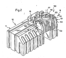
- the bypass device 100 consists essentially of a unitary three-dimensional box 101 delimiting an interior passage space 111 and intended to be mounted directly on the main box 11 of the separator.
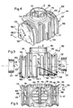
- the figure 1 illustrates the by-pass device 100 before its assembly, and the figure 2 once its assembly done, with the use of bolting or analogues not shown here, for example at the bearing planes 12, 13 of the main box 11.
- the unitary casing 101 comprises two lateral partitions 102, 103 facing each other, defining an inlet 106 and an outlet 107 of said bypass device which are substantially aligned with one another and which constitute the inlet and outlet of the separator when the unitary box 101 is mounted on the main box 11.
- the unit box 101 further comprises a lower partition 104 which, as will be described in more detail later, has two orifices which are superimposed sealed respectively to the inlet 14 of the dewatering compartment of the main box 11 and to the outlet 15 of the separator compartment of the main box 11 when said unitary box 101 is mounted on said main box 11.
- the superposition of the orifices concerned thus realizes a direct connection of the unitary box 101 to the main box 11.
- an upper partition 105 having a manhole 110 allowing direct access to the entire interior passage space 111.
- the unitary casing 101 is mounted entirely outside and in the direct vicinity of the main casing 11 of the separator.
- the separator equipped with its bypass device and made a double distribution slab single above the two boxes, there will be provided two extensions (not shown here) respectively associated with the manhole 16 of the main box 11 and the manhole 110 of the bypass device 100, which implies the presence of a single double-sided or two eyes juxtaposed on the surface.
- the unitary casing 101 is of generally parallelepipedal shape, and when said unitary casing is mounted on the main casing 11 of the separator, the lateral partitions facing each other 102, 103 are essentially vertical, and the upper and lower partitions 104, 105 are essentially horizontal.
- a unitary box may be made of different materials, but it may be noted a preference for a plastic embodiment, especially polyethylene, using an injection-blow molding technique. or better rotational molding. It will also be observed that the unitary box 101 laterally has a stiffening rib 117 which is arranged in vertical directions when said unitary box is mounted on the main box 11.
- the lower partition 104 of the unitary box 101 has a transverse slope 115 forming overflow.
- This figure shows two orifices 108 and 109 of the lower partition 104, which orifices are intended to be superimposed in a sealed manner, respectively to the inlet orifice 14 of the dewatering compartment and to the outlet orifice 15 of the separator compartment. arranged on the main box 11 when said unitary box is connected to said main box. The two orifices 108, 109 above the lower partition 104 are then located on either side of the transverse slope 115 forming overflow.
- the transverse slope forming overflow 115 is arranged so that the passage section of the unitary box 101 at said transverse slope is at least equal to the passage section of the inlet and outlet 106, 107 defined at the lateral partitions 102, 103 of said unitary casing. This makes it possible to avoid significant pressure losses at the crossing of the transverse slope 115, without impairing the overflow function.
- the transverse slope forming overflow 115 is disposed vertically above the manhole 110 formed in the upper partition 105 of the unitary box 101. and direct access to the sensitive part of the bypass device, which is extremely advantageous. Moreover, as this is better visible on the figure 5 the transverse slope forming the overflow 115 divides the lower partition 104 of the unitary caisson 101 into two parts denoted 104.1 and 104.2, which are in this case arranged at a different level, with a higher level on the side of the inlet 106 than the side of the output 107 of said unitary housing. Such a level shift makes it possible to create a slope effect, as is generally provided in the bypass devices, in order to compensate for the pressure drops.
- the screen 120 will generally be constituted by a frame equipped with parallel bars whose respective spacing corresponds to the dimensioning of the solid obstacles to be retained in order to bar access to the septic tank of the separator.
- the inlet side portion 104.1 of the lower partition 104 is equipped with the screen 120 which overcomes the associated orifice 108, and the screen 120 is here arranged, as can be seen on the figure 5 , with a direct support on the transverse slope forming an overflow 115.
- Such an arrangement makes it possible to have a hunting effect generating a natural entrainment of the obstacles which are retained on the screen 120 by the re-entrant flow in order to facilitate the crossing of the slope. transverse forming overflow 115.
- the inlet and outlet 106, 107 of the bypass device 100 are formed by uncapping the associated side walls 102, 103. Such uncapping is illustrated for one of the side walls on the figure 4 .
- the lateral partition 102 which corresponds to the inlet, having a dashed line 106.2 defining the circular contour of a cap 106.1 whose removal defines the inlet orifice 106.
- the opposite lateral partition 103 in order to define the
- Lip seals 112 and 113 are preferably used in order to seal with the respective external connection pipes marked CE for the inlet and CS for the outlet.
- projections 114 and 116 come from manufacturing in the unitary box 101, here with a projection 114 at the inlet and a projection 116 at the outlet, said projections constituting axial stops to limit the penetration of the outer pipes respectively CE and CS. It is thus ensured, during the installation of said pipes by a staff that would not bring sufficient care, to avoid excessive depression which would bring the free end of the pipes to a degree of depression affecting the associated flows to the inlet orifices 108 and 109 of the bypass device, or even leading to a deviation of all the incoming flows.
- the above-mentioned orifices 108 and 109 are in this case equipped with an associated seal 128, 129 intended to cooperate with the packings (not shown) associated with the inlet and outlet orifices 14, 15 of the main casing 11.
- the superposed linings are perfectly applied against each other during bolting associated with the installation of the bypass device on the main box 11. It will also be possible to equip one or the other of the orifices.
- 108, 109 (preferably the inlet port 108) of a tubular rod plunging straight or bent, which is preferably integral with the unit casing, as has been provided for the variant of Figures 7 to 10 which will be described later.
- the unitary casing 101 has a satisfactory stiffening thanks to the lateral ribbing 117 mentioned above, and also to the ribbing 118 of the lower partition 104 which is visible through the manhole 110 on the figure 6 .
- a compartment 20 which is the dewatering compartment
- a compartment 21 which is the separator compartment.
- the entry of the runoff water is in normal regime by an inlet elbow 17.
- the trajectories then borrowed, after the arrow A at the input of the bypass device 100, correspond to the arrows F1, F2, F3, F4, F5, F6.
- the heavy and voluminous particles of the pebble or dense agglomerated type are then deposited at the bottom of the compartment 20 by simple decantation.
- the discharged water then passes, according to the arrow F7, above a partition wall 18 to arrive in the separator compartment 21.
- the inlet of this compartment is constituted by a forced passage 22 leading to the inlet of a filter
- the walls 18 and 23 are placed in vertical slideways constituted by associated ribbings 19 and 24, respectively, provided in the main casing 11. partitions 18 and 23 are thus easily put in place by the associated manhole 16 of the main box 11 in the manner of frames of a bee hive.
- a float 26 constituting an automatic shutter, said float being guided by vertical bars 27 (here four bars) and being arranged to float in the water and flow in the hydrocarbons (whose density is generally between 0.85 and 0.95).
- the run-off water to be treated takes the path from arrow A to arrow B via the arrows F1 to F12, to be declogged and freed of their hydrocarbons.
- a predetermined threshold for example 10 liters / second
- the untreated portion of the runoff simply passes through the bypass device 100 according to the arrow A 'and B' input and output. There is then a substantially straight through flow, with a minimum of pressure losses and a minimum of risk of obstruction, thus with an optimal operation of the bypass device.
- the geometry used here can withstand flow rates of up to 50 liters / second in incoming water flows for 10 liters / second in maximum flow rates treated.
- the mounting of the unitary casing 101 directly on the main casing 11 makes it possible to optimize the useful volume of the main casing 11, unlike the prior arrangements with an internal bypass device at the main casing of the separator, or with a by-pass device. -pass arranged next to the main box of the separator connected to it by horizontal pipes (as is the case in the document US-A-2005 / 103,698 supra).
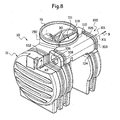
- the essential difference from the first variant lies in the arrangement of the manholes of the two boxes.
- the manhole 110 of the unit casing and the manhole 16 of the main casing 11 are juxtaposed, being here contiguous to vertical walls. contact respectively 119 and 30, and dimensioned to allow the integration of the two accesses in a single visitable view.
- the two manholes 110, 16 have (in horizontal section) complementary profiles forming a regular contour which is here circular. It may alternatively provide other contour geometries, for example rectangular or square.
- the unitary casing 101 is perfectly wedged in the associated receiving housing formed in the casing 11, with a horizontal support on the faces 12, 13 and a vertical support against the face 30. It will however be advantageous to provide a connection consolidating the regular contour. thus formed, for example by bolting the two vertical contact walls 119,30 between they, or, as illustrated on the figure 8 , by a peripheral bandage 150.
- each manhole 16, 110 in particular here that of the narrowest 110, will be chosen to preserve a direct and easy access to the interior space of the box concerned.
- Such an arrangement is very advantageous in practice, because it allows, in addition to the single distribution slab, the integration of the two accesses in a single visitable view (whose maximum dimensioning is generally limited to one meter in diameter).
Abstract
Description
La présente invention est du domaine du traitement des eaux pluviales ou industrielles, et a plus particulièrement pour objet un perfectionnement aux séparateurs à hydrocarbures destinés au traitement d'eaux de ruissellement.The present invention is in the field of rainwater treatment or industrial, and more particularly to an improvement to hydrocarbon separators for the treatment of runoff.
Sur toutes les zones de circulation de véhicules (parkings, voiries, aires de lavage, aires de dépotage, stations service, etc...), les eaux de ruissellement apparaissant en cas de pluies ou de nettoyage renferment une quantité plus ou moins importante d'hydrocarbures, de boues et de diverses matières solides en suspension qu'il est nécessaire d'éliminer avant le rejet en milieu naturel ou en station d'épuration.In all vehicular traffic areas (car parks, roads, washing areas, dumping areas, petrol stations, etc ...), runoff occurring during rain or cleaning contain a greater or lesser amount of water. hydrocarbons, sludge and various suspended solids that must be removed before discharge into a natural environment or wastewater treatment plant.
On a déjà proposé de nombreux séparateurs à hydrocarbures qui sont du type à compartiment débourbeur et compartiment séparateur, ces deux compartiments étant montés en série, de façon que les eaux de ruissellement ayant pénétré dans le séparateur en ressortent dans un état débourbé, et débarrassées des hydrocarbures vers une canalisation de sortie.Numerous hydrocarbon separators have already been proposed which are of the dewatering compartment and separator compartment type, these two compartments being connected in series, so that the runoff water having entered the separator comes out of it in a stripped state, and freed from hydrocarbons to an outlet pipe.
On pourra se référer, au titre de l'arrière-plan technologique, aux documents
En cas d'orages ou de fortes pluies, la situation se complique dans la mesure où des volumes d'eaux de ruissellement avec des débits très importants sont introduits dans le séparateur, lesquels débits d'eaux ne peuvent la plupart du temps être intégralement débarrassés des hydrocarbures qu'ils contiennent. Pour faire face à cette difficulté, on a développé il y a une vingtaine d'années des dispositifs de déviation de flux intégrés aux séparateurs à hydrocarbures, en général appelés dispositifs de by-pass ou déversoirs d'orage. La fonction d'un tel dispositif de by-pass est de recueillir les eaux lors d'une augmentation de débit, ainsi que les eaux n'accédant plus dans le compartiment séparateur lorsque celui-ci est saturé, et de renvoyer directement vers la sortie le flux qui est supérieur à la capacité de traitement du séparateur. En effet, les compartiments séparateurs sont classiquement pourvus d'un système d'obturation automatique, en général à flotteur, qui, en cas de saturation et/ou d'accumulation d'hydrocarbures, vient fermer progressivement la sortie du compartiment séparateur, l'intégralité des eaux en entrée de l'appareil étant alors évacuée directement par le dispositif de by-pass. De façon plus générale, on considère que, sur les zones où la pollution est réputée faible (zones de roulement, parkings, zones de stationnement imperméabilisées), les hydrocarbures sont drainés par les premières eaux d'un élément pluvial. Si la pluviométrie devient très importante, on peut considérer que les surfaces concernées sont déjà débarrassées de la majorité des hydrocarbures légers, et tolérer que le flux plus important traverse le dispositif de by-pass ou déversoir d'orage sans être détourné dans le séparateur proprement dit. Pour l'arrière-plan technologique relatif aux dispositifs de by-pass, on pourra se référer aux documents
Plus récemment, on a proposé un dispositif de by-pass pour séparateurs à hydrocarbures, comportant au moins une canalisation de contournement disposée à l'extérieur du caisson principal du séparateur et reliant des boîtes de connexion d'entrée et de sortie diamétralement opposées, la ou les canalisations de contournement étant conformées pour passer autour d'une cheminée centrale du caisson du séparateur prévue pour l'accès et la surveillance à l'intérieur dudit caisson lorsque celui-ci est enterré.More recently, there has been proposed a bypass device for hydrocarbon separators, comprising at least one bypass line disposed outside the main box of the separator and connecting diametrically opposite input and output connection boxes, the or the bypass lines being shaped to pass around a central chimney of the separator box provided for access and monitoring inside said box when it is buried.
Une telle approche est illustrée dans le document
La structure décrite dans ce document est intéressante dans la mesure où il est proposé une réalisation modulaire du dispositif de by-pass, avec un système en deux demi-anneaux reliant des boîtiers de connexion d'entrée et de sortie diamétralement opposés, lesquels boîtiers présentent inférieurement un manchon cylindrique de raccordement qui est inséré verticalement dans des orifices respectifs d'entrée et de sortie du caisson principal du séparateur, les deux demi-anneaux passant autour de la cheminée centrale dudit caisson. Il devient dès lors possible de construire différents caissons de traitement avec les mêmes éléments, ou de réaliser un séparateur équipé d'une ou deux canalisations de contournement, ou en variante d'aucune canalisation de contournement, sans avoir à changer les boîtiers d'entrée et de sortie et sans avoir à modifier l'agencement intérieur du caisson principal ou la forme de celui-ci.The structure described in this document is interesting insofar as it is proposed a modular embodiment of the bypass device, with a system in two half-rings connecting diametrically opposite input and output connection boxes, which housings present inferiorly a cylindrical connecting sleeve which is inserted vertically into respective inlet and outlet orifices of the main box of the separator, the two half-rings passing around the central chimney of said box. It then becomes possible to construct different treatment boxes with the same elements, or to make a separator equipped with one or two bypass pipes, or alternatively no bypass channel, without having to change the input boxes and output and without having to change the interior layout of the main box or the shape thereof.
Cependant, une telle structure qui était certes séduisante en théorie s'avère présenter de graves inconvénients dans la pratique. En effet, le principe même d'une réalisation en demi-anneaux raccordant des boîtiers de connexion d'entrée et de sortie implique la présence de coudes particulièrement marqués à l'entrée et à la sortie du dispositif de by-pass, sans parler également du trajet incurvé inhérent à la géométrie demi-circulaire des canalisations de contournement. En outre, les canalisations de contournement de forme demi-circulaire présentent un diamètre notablement inférieur à celui de la canalisation d'entrée des eaux de ruissellement à traiter, ce qui multiplie les risques d'obturation en cas de gros obstacles, ou impose un dégrillage des effluents en amont du séparateur, ce qui génère des coûts supplémentaires, sans parler des pertes de charge importantes inhérentes au trajet emprunté par les eaux de ruissellement s'écoulant avec de gros débits en cas d'orages. En plus de ces inconvénients de fonctionnement, une telle structure implique la présence de six à huit garnitures d'étanchéité, ce qui multiplie les risques de fuite, et oblige également à prévoir un nombre important de regards en surface pour permettre l'inspection du système, avec au minimum un regard associé à chaque boîtier de connexion d'entrée et de sortie. Enfin, la complexité de la structure a un effet inévitable sur le coût de production des pièces, même si celles-ci sont réalisées en matière plastique.However, such a structure which was certainly attractive in theory turns out to have serious disadvantages in practice. Indeed, the very principle of a realization in half-rings connecting input and output connection boxes implies the presence of bends particularly marked at the input and output of the bypass device, not to mention also of the curved path inherent in the semicircular geometry of the bypass pipes. In addition, the half-circular bypass lines have a diameter significantly less than that of the inlet pipe of the runoff to be treated, which increases the risks shutter in case of large obstacles, or requires screening of effluents upstream of the separator, which generates additional costs, not to mention significant pressure losses inherent to the path taken by runoff flowing with large flows in case of storms. In addition to these operating disadvantages, such a structure involves the presence of six to eight seals, which increases the risk of leakage, and also requires to provide a large number of surface manholes to allow inspection of the system. , with at least one look associated with each input and output connection box. Finally, the complexity of the structure has an inevitable effect on the cost of production of parts, even if they are made of plastic.
Enfin, le document
Dans ce document, le caisson unitaire est enterré à distance du caisson principal, et il est raccordé à celui-ci par deux tubulures horizontales débouchant sensiblement à mi-hauteur du caisson principal, ces tubulures présentant en outre un coude terminal dans ledit caisson principal.In this document, the unitary box is buried at a distance from the main box, and it is connected thereto by two horizontal pipes opening substantially halfway up the main box, these pipes further having a terminal elbow in said main box.
Un tel agencement présente de nombreux inconvénients :
- il est en effet nécessaire de prévoir deux fosses, l'une pour enterrer le caisson principal et l'autre pour enterrer le caisson unitaire du dispositif de by-pass, et deux dalles de répartition au-dessus de chacun des caissons, d'où une complication du terrassement et de la maçonnerie ;
- le raccordement latéral par des tubulures, outre leur défaut de pente, implique des pertes de charge importantes, et surtout pénalise le volume utile du caisson principal (le niveau d'eau dans celui-ci étant limité au niveau du raccordement) ; et
- les coudes d'entrée présentés par les tubulures de raccordement, outre les pertes de charge, induisent un risque considérable d'obturation par des obstacles tels que branchages ou feuilles.
- it is indeed necessary to provide two pits, one to bury the main box and the other to bury the unit box of the bypass device, and two slabs of distribution above each of the boxes, where a complication of earthworks and masonry;
- the lateral connection by tubing, in addition to their slope fault, involves significant pressure losses, and especially penalizes the useful volume of the main box (the water level in it being limited at the connection); and
- the inlet bends presented by the connecting pipes, in addition to the pressure drops, induce a considerable risk of clogging by obstacles such as branches or leaves.
L'homme de métier pourrait penser rapprocher le caisson unitaire du caisson principal pour éviter le premier inconvénient, mais ceci ne permettrait pas de supprimer les autres inconvénients relatifs à l'écoulement des eaux.The skilled person might think to bring the unitary box closer to the main box to avoid the first disadvantage, but this would not remove the other disadvantages relating to the flow of water.
La présente invention a pour objet de proposer un dispositif de by-pass pour séparateur à hydrocarbures ne présentant pas les inconvénients et/ou limitations des dispositifs précités de l'art antérieur, grâce à une structure dont la simplicité favorise à la fois la mise en place et l'inspection en service, mais aussi la fabrication pour un coût modique.The object of the present invention is to propose a bypass device for a hydrocarbon separator that does not have the disadvantages and / or the limitations of the aforementioned devices of the prior art, thanks to a structure whose simplicity promotes both the implementation of place and inspection in service, but also manufacturing for a small fee.
L'invention a également pour objet de proposer un dispositif de by-pass dont la structure facilite l'implantation, et optimise le volume utile du caisson principal du séparateur, tout en limitant les pertes de charge et les risques d'obturation.The invention also aims to provide a bypass device whose structure facilitates the implementation, and optimizes the useful volume of the main chamber of the separator, while limiting the pressure losses and the risk of clogging.
Le problème technique précité est résolu conformément à l'invention grâce à un dispositif de by-pass du type précité, conformément à la partie caractérisante de la revendication 1.The aforementioned technical problem is solved according to the invention by a bypass device of the aforementioned type, according to the characterizing part of claim 1.
Ainsi, la structure en caisson tridimensionnel unitaire du dispositif de by-pass permet de réaliser une pièce unique qu'il suffit de mettre en place sur le caisson principal du séparateur, et l'alignement de l'entrée et de la sortie du dispositif de by-pass permet d'avoir, en cas très forts débits d'eaux, un écoulement rectiligne exempt de pertes de charge et sans risques d'obturation par des obstacles emportés par les flux d'eaux de ruissellement. Cet écoulement direct dans le caisson tridimensionnel unitaire lui-même représente ainsi un progrès considérable par rapport à la géométrie complexe rappelée ci-dessus utilisant des canalisations de contournement en arcs de cercle raccordées à des boîtiers de connexion d'entrée et de sortie. De plus, l'implantation est facilitée, et le volume utile du caisson principal est optimisé, et ce avec le minimum de pertes de charge et de risques d'obturation.Thus, the unitary three-dimensional box structure of the bypass device makes it possible to produce a single piece that it is sufficient to put in place on the main box of the separator, and the alignment of the input and the output of the device. by-pass makes it possible, in case of very high flow rates, to have a straight flow without any loss of head and without risk of blockage due to obstacles carried by the runoff flow. This direct flow in the unitary three-dimensional box itself thus represents a considerable advance with respect to the complex geometry mentioned above using pipelines. bypassing in arcs connected to input and output connection boxes. In addition, the implementation is facilitated, and the useful volume of the main box is optimized, and with the minimum of pressure losses and shutter risks.
Avantageusement, le caisson unitaire est de forme générale parallélépipédique, et, lorsque ledit caisson unitaire est monté sur caisson principal du séparateur, les cloisons latérales en vis-à-vis sont essentiellement verticales, et les cloisons inférieure et supérieure sont essentiellement horizontales.Advantageously, the unitary box is of parallelepipedal general shape, and when said unitary box is mounted on the main box of the separator, the side walls vis-à-vis are essentially vertical, and the lower and upper partitions are essentially horizontal.
Il est alors particulièrement intéressant de prévoir que la cloison inférieure du caisson unitaire présente un talus transversal formant surverse, les deux orifices de ladite cloison inférieure étant situés de part et d'autre dudit talus transversal. Un tel talus transversal formant surverse est très intéressant pour limiter le débit entrant dans le séparateur par ajutage.It is then particularly advantageous to provide that the lower wall of the unitary caisson has a transverse slope forming an overflow, the two orifices of said lower partition being located on either side of said transverse slope. Such a transverse slope forming an overflow is very advantageous for limiting the flow entering the nozzle separator.
De préférence alors, le talus transversal formant surverse est agencé de façon que la section de passage du caisson unitaire au niveau dudit talus transversal soit au moins égale à la section de passage de l'entrée et de la sortie définies au niveau des cloisons latérales dudit caisson unitaire. Ceci permet à la fois d'éviter des pertes de charge défavorables et d'écarter des risques inutiles d'obturation en cas de passage d'obstacles transportés par les eaux de ruissellement à gros débits.Preferably then, the transverse slope forming the overflow is arranged so that the passage section of the unitary box at said transverse slope is at least equal to the passage section of the inlet and the outlet defined at the side walls of said unitary box. This makes it possible both to avoid unfavorable pressure drops and to avoid unnecessary risks of closure when obstacles are transported by the runoff water at large flows.
Avantageusement encore, le talus transversal formant surverse est disposé à l'aplomb du trou d'homme ménagé dans la cloison supérieure du caisson unitaire. En effet, cette position du trou d'homme permet une inspection rapide, et une éventuelle intervention directe en cas d'obstruction au niveau de la partie sensible du dispositif de by-pass.Advantageously, the transverse slope forming the overflow is disposed vertically above the manhole formed in the upper wall of the unitary caisson. Indeed, this position of the manhole allows a quick inspection, and a possible direct intervention in case of obstruction at the sensitive part of the bypass device.
Il est également intéressant de prévoir que le talus transversal formant surverse partage la cloison inférieure du caisson unitaire en deux parties qui sont agencées à un niveau différent, avec un niveau plus élevé du côté de l'entrée que du côté de la sortie dudit caisson unitaire. Un tel agencement a pour effet de favoriser l'écoulement en créant une pente descendante de l'entrée vers la sortie qui compense les pertes de charge.It is also advantageous to provide that the transverse slope forming the overflow shares the lower partition of the unitary caisson into two parts which are arranged at a different level, with a higher level on the inlet side than on the outlet side of said unitary caisson. . Such an arrangement has the effect of promoting the flow by creating a downward slope from the inlet to the outlet which compensates for pressure losses.
On pourra alors prévoir que la partie entrée de la cloison inférieure du caisson unitaire est équipée d'un dégrilleur surmontant l'orifice associé de ladite cloison inférieure. En particulier, le dégrilleur prend directement appui sur le talus transversal formant surverse. Grâce à un tel dégrilleur les éventuels objets solides sont retenus et ne pénètrent pas dans le compartiment débourbeur du séparateur, et ces objets sont en plus repoussés par le flux des eaux rentrantes jusqu'à franchir grâce à l'effet de chasse le talus transversal formant surverse et gagner ensuite la sortie du dispositif de by-pass.It can then be provided that the entrance portion of the lower partition of the unitary box is equipped with a screen overlying the associated orifice of said lower partition. In particular, the screen is directly supported on the transverse slope forming overflow. Thanks to such a screen any solid objects are retained and do not enter the separator compartment separator, and these objects are further repelled by the incoming water flow to cross through the effect of hunting the transverse slope forming overflow and then gain the output of the bypass device.
Il est par ailleurs intéressant de prévoir que l'entrée et la sortie dudit dispositif de by-pass sont formées par désoperculage des cloisons latérales associées. Ceci permet de découper les orifices d'entrée et de sortie en choisissant un diamètre compatible avec le débit maximum toléré. On pourra procéder de même pour les deux orifices ménagés dans la cloison inférieure du caisson unitaire, ou en variante équiper l'orifice d'entrée d'une canne tubulaire plongeante.It is also advantageous to provide that the input and output of said bypass device are formed by uncapping the associated side walls. This makes it possible to cut out the inlet and outlet ports by choosing a diameter compatible with the maximum permissible flow rate. The same can be done for the two orifices formed in the lower wall of the unitary box, or alternatively to equip the inlet port of a tubular plunger.
Avantageusement, l'entrée et la sortie sont en outre équipées d'une garniture d'étanchéité et d'une butée axiale agencée pour limiter l'enfoncement d'une canalisation extérieure respective de raccordement.Advantageously, the inlet and the outlet are furthermore equipped with a seal and an abutment axial arranged to limit the depression of a respective external connection pipe.
Par ailleurs, pour faciliter encore l'implantation en réduisant le terrassement et la maçonnerie, il est intéressant de prévoir que, lorsque le caisson unitaire est monté sur le caisson principal, les trous d'homme desdits caissons sont juxtaposés et dimensionnés pour permettre l'intégration des deux accès dans un regard visitable unique.Moreover, to further facilitate the implementation by reducing the earthwork and masonry, it is interesting to provide that, when the unitary box is mounted on the main box, the manholes of said boxes are juxtaposed and sized to allow the integration of both accesses into a single visitable look.
De préférence alors, les deux trous d'homme sont accolés par deux parois verticales de contact et ont des profils complémentaires formant un contour régulier, en particulier un contour circulaire, rectangulaire ou carré.Preferably then, the two manholes are joined by two vertical contact walls and have complementary profiles forming a regular contour, in particular a circular, rectangular or square contour.
Avantageusement dans ce cas, le contour régulier ainsi formé est consolidé par un boulonnage des deux parois verticales de contact entre elles, ou en variante par un sanglage périphérique.Advantageously in this case, the regular contour thus formed is consolidated by bolting the two vertical walls of contact between them, or alternatively by a peripheral webbing.
De préférence encore, le caisson unitaire présente latéralement un nervurage de rigidification qui est agencé selon des directions verticales lorsque ledit caisson unitaire est monté sur le caisson principal.More preferably, the unitary casing laterally has a stiffening rib which is arranged in vertical directions when said unitary box is mounted on the main box.
Avantageusement enfin, le caisson unitaire est réalisé en matière plastique, notamment en polyéthylène, de préférence par rotomoulage.Advantageously finally, the unitary box is made of plastics material, especially polyethylene, preferably by rotational molding.
D'autres caractéristiques et avantages de l'invention apparaîtront plus clairement à la lumière de la description qui va suivre et des dessins annexés, illustrant un mode de réalisation particulier.Other features and advantages of the invention will appear more clearly in the light of the description which follows and the accompanying drawings, illustrating a particular embodiment.
Il sera fait référence aux figures des dessins annexés, où :
- les
figures 1 et2 illustrent en perspective un séparateur à hydrocarbures équipé d'un dispositif de by-pass conforme à l'invention, selon une première variante, respectivement en vue éclatée et en vue montée dudit dispositif ; - la
figure 3 est une vue en coupe du séparateur précité au niveau de ses compartiments débourbeur et séparateur, avec des flèches illustrant d'une part les flux d'écoulement en cas de débits inférieurs à une limite prédéterminée, pour lesquels le dispositif de by-pass n'intervient pas, et d'autre part les flux d'écoulement pour les écoulements dépassant la limite précitée en cas de fortes pluies, pour lesquels le dispositif de by-pass entre automatiquement en fonction en permettant un écoulement direct et sensiblement rectiligne des eaux qui ne pénètrent pas dans le compartiment débourbeur du séparateur ; - la
figure 4 illustre en perspective le dispositif de by-pass seul, dont la face latérale visible est ici représentée dans son état antérieur au désoperculage destiné à définir l'orifice d'entrée ; - la
figure 5 est une vue regroupant une demi-vue latérale en partie haute et une demi-coupe en partie basse afin de mieux distinguer l'agencement des orifices de la cloison inférieure de part et d'autre d'un talus transversal formant surverse, ainsi que divers aménagements avantageux ; - la
figure 6 est une vue de dessus du dispositif, illustrant l'accès général et central par le trou d'homme supérieur à l'aplomb duquel est prévu le talus transversal formant surverse ; - les
figures 7 et8 , analogues auxfigures 1 et2 , illustrent une deuxième variante dans laquelle les trous d'homme des deux caissons ont des profils complémentaires pour permettre l'intégration des deux accès dans un regard visitable unique ; - les
figures 9 et 10 sont des vues en perspective et de côté du dispositif de by-pass seul, selon cette deuxième variante, et - la
figure 11 est une coupe selon XI-XI de lafigure 10 .
- the
figures 1 and2 illustrate in perspective a hydrocarbon separator equipped with a bypass device according to the invention, according to a first variant, respectively in an exploded view and mounted view of said device; - the
figure 3 is a cross-sectional view of the aforementioned separator at its separator and separator compartments, with arrows illustrating, on the one hand, the flow flows in the case of flow rates lower than a predetermined limit, for which the bypass device does not does not intervene, and on the other hand flow flows for flows exceeding the above limit in case of heavy rain, for which the bypass device automatically enters into operation allowing a direct and substantially straight flow of water that does not do not enter the separator compartment of the separator; - the
figure 4 illustrates in perspective the bypass device alone, whose visible side face is here represented in its state prior to uncapping to define the inlet port; - the
figure 5 is a view combining a half-side view at the top and a half-section at the bottom to better distinguish the arrangement of the orifices of the lower partition on either side of a transverse slope forming an overflow, as well as various advantageous arrangements; - the
figure 6 is a top view of the device, illustrating the general and central access through the manhole greater than the perpendicular of which is provided the transverse slope forming overflow; - the
figures 7 and8 , similar tofigures 1 and2 , illustrate a second variant in which the manholes of the two boxes have complementary profiles to allow the integration of the two accesses in a single visitable view; - the
Figures 9 and 10 are perspective and side views of the bypass device alone, according to this second variant, and - the
figure 11 is a section according to XI-XI of thefigure 10 .
Sur les
Le caisson principal 11 présente extérieurement deux plans d'appui essentiellement horizontaux 12, 13, présentant des orifices respectifs, 14, 15 qui constituent respectivement l'entrée du compartiment débourbeur et la sortie du compartiment séparateur. En l'espèce, les plans d'appui 12, 13 sont à des niveaux différents, avec un niveau plus élevé pour l'entrée que pour la sortie, ceci pour organiser une pente naturelle associée au dispositif de by-pass 100 comme cela sera expliqué par la suite.The
Le dispositif de by-pass 100 conforme à l'invention est essentiellement constitué par un caisson tridimensionnel unitaire 101 délimitant un espace intérieur de passage 111 et destiné à être monté directement sur le caisson principal 11 du séparateur. La
Le caisson unitaire 101 comporte deux cloisons latérales 102, 103 en vis-à-vis, définissant une entrée 106 et une sortie 107 dudit dispositif de by-pass qui sont sensiblement alignées l'une par rapport à l'autre et qui constituent l'entrée et la sortie du séparateur lorsque le caisson unitaire 101 est monté sur le caisson principal 11. Le caisson unitaire 101 comporte en outre une cloison inférieure 104 qui, comme cela sera décrit plus en détail par la suite, présente deux orifices qui sont superposés de façon étanche respectivement à l'orifice d'entrée 14 du compartiment débourbeur du caisson principal 11 et à l'orifice de sortie 15 du compartiment séparateur du caisson principal 11 lorsque ledit caisson unitaire 101 est monté sur ledit caisson principal 11. La superposition des orifices concernés réalise ainsi un raccordement direct du caisson unitaire 101 au caisson principal 11. Il est enfin prévu une cloison supérieure 105 présentant un trou d'homme 110 autorisant un accès direct à la totalité de l'espace intérieur de passage 111.The
Le caisson unitaire 101 est monté en totalité à l'extérieur et au voisinage direct du caisson principal 11 du séparateur. Dans la pratique, une fois enterré le séparateur équipé de son dispositif de by-pass, et réalisé une double dalle de répartition unique au-dessus des deux caissons, il sera prévu deux rehausses (non représentées ici) associées respectivement au trou d'homme 16 du caisson principal 11 et au trou d'homme 110 du dispositif de by-pass 100, ce qui implique la présence d'un unique double regard ou de deux regards juxtaposés en surface.The
Dans la pratique, dans la situation de la
Pour les écoulements à faibles débits d'eaux de ruissellement, on aura compris que les débits d'eaux concernés arrivant selon la flèche A à l'entrée du dispositif de by-pass 100 pénètrent dans le compartiment débourbeur du caisson principal 11 pour en ressortir par le compartiment séparateur dudit caisson principal 11, et s'échapper finalement par la sortie du dispositif de by-pass 100 conformément à la flèche B. En cas de très gros débits, correspondant à une situation de fortes pluies ou d'orages violents, la majeure partie des écoulements, en général 80 % du débit maximum admissible, passe directement de l'entrée à la sortie du dispositif de by-pass 100 conformément aux flèches A' et B', selon un écoulement en trace directe essentiellement rectiligne.For flows with low flow rates of runoff, it will be understood that the water flows concerned arriving according to the arrow A at the entrance of the
Conformément à la structure présentement illustrée, le caisson unitaire 101 est de forme générale parallélépipédique, et, lorsque ledit caisson unitaire est monté sur le caisson principal 11 du séparateur, les cloisons latérales en vis-à-vis 102, 103 sont essentiellement verticales, et les cloisons supérieure et inférieure 104, 105 sont essentiellement horizontales. Un tel caisson unitaire pourra être réalisé dans différents matériaux, mais on peut relever une préférence pour une réalisation en matière plastique, notamment en polyéthylène, en utilisant une technique d'injection-soufflage ou mieux de rotomoulage. On observera également que le caisson unitaire 101 présente latéralement un nervurage de rigidification 117 qui est agencé selon des directions verticales lorsque ledit caisson unitaire est monté sur le caisson principal 11.According to the structure currently illustrated, the
On va maintenant décrire plus en détail la structure du caisson unitaire tridimensionnel 101 du dispositif de by-pass 100 en référence aux
Comme cela est mieux visible sur la
De préférence, le talus transversal formant surverse 115 est agencé de façon que la section de passage du caisson unitaire 101 au niveau dudit talus transversal soit au moins égale à la section de passage de l'entrée et de la sortie 106, 107 définies au niveau des cloisons latérales 102, 103 dudit caisson unitaire. Ceci permet d'éviter des pertes de charge sensibles au niveau du franchissement du talus transversal 115, sans nuire à la fonction de surverse.Preferably, the transverse
Comme cela est mieux visible sur les
On a également représenté sur la
Il est par ailleurs intéressant de prévoir que l'entrée et la sortie 106, 107 du dispositif de by-pass 100 sont formées par désoperculage des cloisons latérales associées 102, 103. Un tel désoperculage est illustré pour l'une des cloisons latérales sur la
Le caisson unitaire 101 présente une rigidification satisfaisante grâce au nervurage latéral 117 précité, et aussi au nervurage 118 de la cloison inférieure 104 qui est visible par le trou d'homme 110 sur la
On est ainsi parvenu à réaliser un caisson unitaire qui assure toutes les fonctions associées au passage des écoulements, en particulier la fonction de by-pass pour les très forts débits avec un écoulement direct essentiellement rectiligne, cette structure unitaire pouvant être aisément réalisée en matière plastique par injection-soufflage ou mieux encore par rotomoulage. L'ensemble unitaire réalisé par rotomoulage présente alors des cloisons complètes qu'il suffit de désoperculer pour réaliser les orifices souhaités, en particulier les orifices 106 et 107 d'entrée et de sortie et les orifices 108 et 109 de communication avec les compartiments débourbeur et séparateur du caisson principal, les diamètres de ces quatre orifices étant choisis en fonction du débit maximal souhaité pour le dispositif de by-pass.It has thus been possible to produce a unitary box which provides all the functions associated with the passage of the flows, in particular the bypass function for the very high flow rates with a direct flow that is essentially straight, this unitary structure being easily made of plastics material. by injection-blowing or better still by rotational molding. The unitary assembly produced by rotomolding then has complete partitions that it is sufficient to uncap to achieve the desired orifices, in particular the
On aura compris qu'une telle structure est extrêmement avantageuse tant sur le plan du fonctionnement que sur le plan de la fabrication.It will be understood that such a structure is extremely advantageous both in terms of operation and in terms of manufacturing.
On va maintenant brièvement décrire le fonctionnement du séparateur en se référant à la
On distingue sur la
On a également représenté ici un flotteur 26 constituant un obturateur automatique, ledit flotteur étant guidé par des barreaux verticaux 27 (ici quatre barreaux) et étant agencé pour flotter dans l'eau et couler dans les hydrocarbures (dont la densité est généralement comprise entre 0,85 et 0,95). Par suite, plus la couche d'hydrocarbures collectée augmente, plus le flotteur descend, jusqu'à ce qu'il obstrue la sortie du compartiment séparateur quand la couche a atteint son niveau maximal tolérable.There is also shown here a
Ainsi, en utilisation normale correspondant à un débit inférieur à un seuil prédéterminé, par exemple 10 litres/seconde, les eaux de ruissellement à traiter empruntent le trajet allant de la flèche A à la flèche B en passant par les flèches F1 à F12, de façon à être débourbées et débarrassées de leurs hydrocarbures. En cas de fortes pluies ou d'orages violents, les débits dépassent le seuil prédéterminé, et dans ce cas la partie non traitée des eaux de ruissellement traverse simplement le dispositif de by-pass 100 conformément aux flèche A' et B' d'entrée et de sortie. On dispose alors d'un écoulement traversant sensiblement rectiligne, avec un minimum de pertes de charge et un minimum de risques d'obstruction, avec donc un fonctionnement optimal du dispositif de by-pass. A titre indicatif, la géométrie utilisée ici permet de supporter des débits allant jusqu'à 50 litres/seconde en débits d'eau entrants pour 10 litres/seconde en débits maximum traités.Thus, in normal use corresponding to a flow rate below a predetermined threshold, for example 10 liters / second, the run-off water to be treated takes the path from arrow A to arrow B via the arrows F1 to F12, to be declogged and freed of their hydrocarbons. In the event of heavy rain or thunderstorms, the flows exceed the predetermined threshold, and in this case the untreated portion of the runoff simply passes through the
On notera également que le montage du caisson unitaire 101 directement sur le caisson principal 11 permet d'optimiser le volume utile du caisson principal 11, contrairement aux agencements antérieurs à dispositif de by-pass intérieur au caisson principal du séparateur, ou à dispositif de by-pass agencé à côté du caisson principal du séparateur raccordé à celui-ci par des tubulures horizontales (comme c'est le cas dans le document
Bien entendu, en cas de dysfonctionnement imprévu du séparateur, par suite d'une obstruction en un point donné de celui-ci ou d'une saturation complète du niveau d'hydrocarbures, l'ensemble de l'écoulement entrant traverse le dispositif de by-pass en trace directe, comme en cas de fortes pluies.Of course, in the event of an unexpected failure of the separator, as a result of a one-point obstruction given from it or a complete saturation of the hydrocarbon level, the whole of the incoming flow passes through the by-pass device in direct trace, as in the case of heavy rains.
On est ainsi parvenu à réaliser un dispositif de by-pass qui est à la fois de structure simple et de fonctionnement optimal, permettant d'éviter très largement les limitations et inconvénients des dispositifs de l'art antérieur précités.It has thus been possible to produce a bypass device which is both of simple structure and of optimal operation, making it possible to largely avoid the limitations and disadvantages of the devices of the aforementioned prior art.
On va maintenant décrire une deuxième variante qui est illustrée aux
La différence essentielle par rapport à la première variante réside dans l'agencement des trous d'homme des deux caissons.The essential difference from the first variant lies in the arrangement of the manholes of the two boxes.
On constate en effet que, lorsque le caisson unitaire 101 est monté sur le caisson principal 11, le trou d'homme 110 du caisson unitaire et le trou d'homme 16 du caisson principal 11 sont juxtaposés, en étant ici accolés par des parois verticales de contact respectivement 119 et 30, et dimensionnés pour permettre l'intégration des deux accès dans un regard visitable unique. Les deux trous d'homme 110, 16 ont (en section horizontale) des profils complémentaires formant un contour régulier qui est ici circulaire. On pourra en variante prévoir d'autres géométries de contour, par exemple rectangulaire ou carrée.It can be seen that, when the
Le caisson unitaire 101 est parfaitement calé dans le logement de réception associé formé dans le caisson 11, avec un appui horizontal sur les faces 12, 13 et un appui vertical contre la face 30. Il sera cependant avantageux de prévoir une liaison consolidant le contour régulier ainsi formé, par exemple par boulonnage des deux parois verticales de contact 119,30 entre elles, ou encore, comme cela a été illustré sur la
Le dimensionnement de chaque trou d'homme 16, 110, en particulier ici celui du plus étroit 110, sera choisi pour préserver un accès direct et aisé à l'espace intérieur du caisson concerné.The sizing of each
On notera également ici la présence d'une canne tubulaire plongeante 108' associée à l'orifice d'entrée 108, laquelle canne pénètre par l'orifice 14 dans le caisson principal 11. En l'espèce, cette canne 108' est rectiligne, mais on pourra prévoir une forme coudée comme dans la première variante.Note also here the presence of a tubular dipping rod 108 'associated with the
Un tel agencement est très avantageux dans la pratique, car il permet, en plus de la dalle unique de répartition, l'intégration des deux accès dans un regard visitable unique (dont le dimensionnement maximum est en général limité à un mètre de diamètre).Such an arrangement is very advantageous in practice, because it allows, in addition to the single distribution slab, the integration of the two accesses in a single visitable view (whose maximum dimensioning is generally limited to one meter in diameter).
Pour le reste, on a les mêmes agencements et composants que pour la variante précédemment décrite, avec les mêmes avantages.For the rest, we have the same arrangements and components as for the variant described above, with the same advantages.
L'invention n'est pas limitée aux modes de réalisation qui viennent d'être décrits, mais englobe au contraire toute autre variante reprenant, avec des moyens équivalents, les caractéristiques essentielles énoncées plus haut.The invention is not limited to the embodiments which have just been described, but on the contrary covers any other variant using, with equivalent means, the essential characteristics stated above.
Claims (16)
- A by-pass device for a hydrocarbon separator intended for the processing of run-off water, of the main tank (11) type, including a washing compartment and a separating compartment on either side of a man-hole (16), with said by-pass device being composed of a three-dimension unit tank (101) delimiting an internal flow passage (111) and intended to be connected to the main tank (11) of the separator, said unit tank (101) including:- two opposite side partition walls (102, 103) defining an inlet (106) and an outlet (107) of said by-pass device which are substantially aligned with each other and an upper partition wall (105) provided with a man-hole (110) enabling a direct access to the internal flow passage (111),
characterized in that the unit tank (101) is arranged so as to be directly mounted on the main tank (11) of the separator,- the inlet (106) and the outlet (107) are the inlet and the outlet of the separator when the unit tank (101) is mounted on the main tank (11), and said unit tank includes:- a lower partition wall (104) intended to be directly supported by the main tank (11), with said lower partition wall having two holes (108, 109) which are sealingly superimposed on an inlet (14) of the washing compartment (20) of the main tank (11) and on an outlet (15) of the separating compartment (21) of the main tank (11) respectively, when said unit tank (101) is mounted on said main tank (11), with the superimposition of the concerned holes (108, 14; 109, 15) providing a direct connection of said unit tank with said main tank. - A by-pass device according to claim 1, characterized in that the unit tank (101) has a general parallelepiped shape, and in that, when said unit tank (101) is mounted on the main tank (11) of the separator, the opposite side partition walls (102, 103) are substantially vertical, and the lower and upper partition walls (104, 105) are substantially horizontal.
- A by-pass device according to claim 2, characterized in that the lower partition wall (104) of the unit tank (101) has an overflow-forming transversal cross slope (115), with both holes (108, 109) in said lower partition wall being located on either side of the transversal cross slope.
- A by-pass device according to claim 3, characterized in that the overflow-forming transversal cross slope (115) is arranged so that the flow area of the unit tank (101) at said transversal cross slope is at least equal to the flow area of the inlet and the outlet (106, 107) defined at the side partition walls (102, 103) of said unit tank.
- A by-pass device according to claim 3 or claim 4, characterized in that the overflow-forming transversal cross slope (115) is positioned straight under the man-hole (110) arranged in the upper partition wall (105) of the unit tank (101).
- A by-pass device according to one of claims 3 to 5, characterized in that the overflow-forming transversal cross slope (115) divides the lower partition wall (104) of the unit tank (101) into two parts (104.1, 104.2) which are arranged at different levels, with a higher level on the inlet (106) side than on the outlet (107) side of said unit tank.
- A by-pass according to claim 6, characterized in that the inlet side part (104.1) of the lower wall (104) of the unit tank (101) is provided with a screen (120) located above the associated hole (108) of said lower partition wall.
- A by-pass device according to claim 7, characterized in that the screen (120) is directly supported by the overflow-forming transversal cross slope (115).
- A by-pass device according to one of claims 1 to 8, characterized in that the inlet and the outlet (106, 107) of said by-pass device are formed by the uncapping of the associated side partition walls (102, 103).
- A by-pass device according to claim 9, characterized in that the inlet and the outlet (106, 107) are further equipped with a gland packing (112, 113) and an axial stop (114, 116) arranged so as to limit the sinking of a respective external connection line (CE, CS).
- A by-pass device according to one of claims 1 to 10, characterized in that, when the unit tank (101) is mounted on the main tank (11), the man-holes (110, 16) of said tanks are placed side by side, and their dimensions are so as to enable the integration of both accesses in a single walk-in inspection hole.
- A device according to claim 11, characterized in that the two man-holes (110, 16) are joined by two contact vertical walls (119, 30) and have complementary profiles forming a regular outline, more particularly a circular, rectangular or square outline.
- A device according to claim 12, characterized in that the regular outline thus formed is strengthened by the bolting together of both contact vertical walls (119, 30).
- A device according to claim 12, characterized in that the regular outline thus formed is strengthened by a peripheral edging (150).
- A by-pass device according to one of claims 1 to 14, characterized in that the unit tank (101) has a stiffening ribbing (117) which is arranged along vertical directions when said unit tank is mounted on the main tank (11).
- A by-pass device according to one of claims 1 to 15, characterized in that the unit tank (101) is made of a plastic material, more particularly of polyethylene, preferably by rotational moulding.
Applications Claiming Priority (1)
| Application Number | Priority Date | Filing Date | Title |
|---|---|---|---|
| FR0705626A FR2919635B1 (en) | 2007-08-01 | 2007-08-01 | PY-PASS DEVICE FOR HYDROCARBON SEPARATOR FOR TREATING RUNOFF WATER |
Publications (2)
| Publication Number | Publication Date |
|---|---|
| EP2020465A1 EP2020465A1 (en) | 2009-02-04 |
| EP2020465B1 true EP2020465B1 (en) | 2010-12-08 |
Family
ID=39203087
Family Applications (1)
| Application Number | Title | Priority Date | Filing Date |
|---|---|---|---|
| EP08290509A Active EP2020465B1 (en) | 2007-08-01 | 2008-06-03 | Bypass device for a hydrocarbon separator designed for treating runoff water |
Country Status (4)
| Country | Link |
|---|---|
| EP (1) | EP2020465B1 (en) |
| AT (1) | ATE491069T1 (en) |
| DE (1) | DE602008003868D1 (en) |
| FR (1) | FR2919635B1 (en) |
Families Citing this family (2)
| Publication number | Priority date | Publication date | Assignee | Title |
|---|---|---|---|---|
| FR2944814A1 (en) | 2009-04-24 | 2010-10-29 | Eudoise D Environnement Et De | HYDROCARBON SEPARATOR FOR THE TREATMENT OF RUNOFF WATERS |
| DE102012008734A1 (en) * | 2012-05-04 | 2013-11-07 | Heinrich Meier Eisengiesserei Gmbh & Co. Kg | Filter assembly and method for installing the filter assembly |
Family Cites Families (9)
| Publication number | Priority date | Publication date | Assignee | Title |
|---|---|---|---|---|
| FR2577917B1 (en) | 1985-02-26 | 1991-04-26 | Saint Dizier Ste Cale | HYDROCARBON SEPARATOR HYDROFILTER WITH ASSOCIATED COALESCING FILTER |
| FR2642745B1 (en) | 1989-02-08 | 1991-05-10 | Saint Dizier Ste Cale Financie | HYDROCARBON SEPARATORS WITH BY-PASS DEVICES |
| FR2654950B1 (en) | 1989-11-29 | 1992-03-06 | Saint Dizier Ste Cale | COALESCENCE OIL-WATER SEPARATOR. |
| FR2754871B1 (en) | 1996-10-21 | 1998-12-11 | Simop | WATER FLOW REGULATOR AND LOADED WATER PURIFICATION INSTALLATION FOR SEPARATING SLUDGE AND HYDROCARBONS, EQUIPPED WITH SUCH A REGULATOR |
| NL1015934C1 (en) * | 2000-08-15 | 2002-02-18 | Aqa Watertechniek B V | Prefabricated built-in component for separator is placed in a well or tank for provision of improved fluid-fluid and/or fluid-solid matter separation |
| FR2836471B1 (en) | 2002-02-22 | 2005-01-14 | Simop | TANK FOR TREATING RUNOFF WATER AND DEGRILL FOR SUCH A TANK |
| US7470361B2 (en) * | 2003-11-14 | 2008-12-30 | Eberly Christopher N | System for stormwater environmental control |
| US7182874B2 (en) * | 2004-02-20 | 2007-02-27 | Kristar Enterprises, Inc. | Storm water treatment apparatus employing dual vortex separators |
| FR2881737B1 (en) | 2005-02-04 | 2007-09-21 | Techneau Soc Par Actions Simpl | TANK FOR TREATING RUNOFF WATER |
-
2007
- 2007-08-01 FR FR0705626A patent/FR2919635B1/en not_active Expired - Fee Related
-
2008
- 2008-06-03 AT AT08290509T patent/ATE491069T1/en not_active IP Right Cessation
- 2008-06-03 DE DE602008003868T patent/DE602008003868D1/en active Active
- 2008-06-03 EP EP08290509A patent/EP2020465B1/en active Active
Also Published As
| Publication number | Publication date |
|---|---|
| EP2020465A1 (en) | 2009-02-04 |
| FR2919635B1 (en) | 2012-12-14 |
| ATE491069T1 (en) | 2010-12-15 |
| DE602008003868D1 (en) | 2011-01-20 |
| FR2919635A1 (en) | 2009-02-06 |
Similar Documents
| Publication | Publication Date | Title |
|---|---|---|
| FR2596437A1 (en) | SEPTIC TANK ALL WATER | |
| EP2020465B1 (en) | Bypass device for a hydrocarbon separator designed for treating runoff water | |
| FR2536739A1 (en) | Horizontal separator. | |
| FR2907022A1 (en) | Effluent treatment unit, especially for treating rainwater from overflow tank, comprises tank formed by assembling annular modules and having decantation and filtration compartments | |
| EP0770735B1 (en) | Underground buffer tank for storing and treating rain water | |
| EP1722039A1 (en) | Device for storing rain water | |
| FR2733700A1 (en) | ENCLOSURES WITH ENHANCED ENHANCEMENT OF SOLID PARTICLES | |
| EP2246105A1 (en) | Hydrocarbon separator designed for treating runoff water | |
| EP0844031B1 (en) | System for treating and discharging groundwater from a polluted site isolated from the environment by an impervious wall in the soil | |
| FR2745195A1 (en) | RETENTION FILTER, INSTALLATION AND PROCESS FOR TREATING EFFLUENTS | |
| EP3008018B1 (en) | Compact filter for a non-collective wastewater sanitizing system | |
| EP2298429B1 (en) | Filtering device and installation for recovering rainwater provided with such a device | |
| FR2788511A1 (en) | Domestic water purification in a device which fits into a kitchen cupboard and treats the entire water demand of the household | |
| FR2982357A1 (en) | Installation for recovering heat from fluid circulating in drain in sewage system, has heat exchanger installed on circuit, and connection junction installed in point downstream of drain, to which fluid part is reinjected into drain | |
| FR2642745A1 (en) | Separators for hydrocarbons provided with bypass devices | |
| FR3046184A1 (en) | WATER COLLECTION AND EVACUATION WATER WITH SOLIDARITY PLATE OF A FLOAT | |
| EP0232664B1 (en) | Duct unit for a plurality of network systems | |
| FR2667514A1 (en) | Improved hydrocarbon separator | |
| EP4101999A1 (en) | Multi-purpose tank for treating and/or temporary storage of a liquid | |
| FR3060621A1 (en) | REGARDING AVALER WITH A COUPLED TUBE | |
| BE1021178B1 (en) | EQUIPMENT FOR REALIZING A WASTEWATER TREATMENT STATION | |
| FR3068051A1 (en) | WASTEWATER MANAGEMENT SYSTEM | |
| EP2136008A1 (en) | Hydrocarbon separator designed for treating runoff water | |
| KR20230155205A (en) | Non-powered rainwater filtration device | |
| FR2954300A1 (en) | DEVICE FOR PRE-COLLECTING WASTE, ITS USE, URBAN PARKING INFRASTRUCTURE AND CORRESPONDING METHOD |
Legal Events
| Date | Code | Title | Description |
|---|---|---|---|
| PUAI | Public reference made under article 153(3) epc to a published international application that has entered the european phase |
Free format text: ORIGINAL CODE: 0009012 |
|
| AK | Designated contracting states |
Kind code of ref document: A1 Designated state(s): AT BE BG CH CY CZ DE DK EE ES FI FR GB GR HR HU IE IS IT LI LT LU LV MC MT NL NO PL PT RO SE SI SK TR |
|
| AX | Request for extension of the european patent |
Extension state: AL BA MK RS |
|
| 17P | Request for examination filed |
Effective date: 20090720 |
|
| AKX | Designation fees paid |
Designated state(s): AT BE BG CH CY CZ DE DK EE ES FI FR GB GR HR HU IE IS IT LI LT LU LV MC MT NL NO PL PT RO SE SI SK TR |
|
| GRAP | Despatch of communication of intention to grant a patent |
Free format text: ORIGINAL CODE: EPIDOSNIGR1 |
|
| GRAS | Grant fee paid |
Free format text: ORIGINAL CODE: EPIDOSNIGR3 |
|
| GRAA | (expected) grant |
Free format text: ORIGINAL CODE: 0009210 |
|
| AK | Designated contracting states |
Kind code of ref document: B1 Designated state(s): AT BE BG CH CY CZ DE DK EE ES FI FR GB GR HR HU IE IS IT LI LT LU LV MC MT NL NO PL PT RO SE SI SK TR |
|
| REG | Reference to a national code |
Ref country code: GB Ref legal event code: FG4D Free format text: NOT ENGLISH |
|
| REG | Reference to a national code |
Ref country code: CH Ref legal event code: EP |
|
| REG | Reference to a national code |
Ref country code: IE Ref legal event code: FG4D |
|
| REF | Corresponds to: |
Ref document number: 602008003868 Country of ref document: DE Date of ref document: 20110120 Kind code of ref document: P |
|
| REG | Reference to a national code |
Ref country code: NL Ref legal event code: VDEP Effective date: 20101208 |
|
| PG25 | Lapsed in a contracting state [announced via postgrant information from national office to epo] |
Ref country code: NO Free format text: LAPSE BECAUSE OF FAILURE TO SUBMIT A TRANSLATION OF THE DESCRIPTION OR TO PAY THE FEE WITHIN THE PRESCRIBED TIME-LIMIT Effective date: 20110308 Ref country code: LT Free format text: LAPSE BECAUSE OF FAILURE TO SUBMIT A TRANSLATION OF THE DESCRIPTION OR TO PAY THE FEE WITHIN THE PRESCRIBED TIME-LIMIT Effective date: 20101208 |
|
| LTIE | Lt: invalidation of european patent or patent extension |
Effective date: 20101208 |
|
| PG25 | Lapsed in a contracting state [announced via postgrant information from national office to epo] |
Ref country code: FI Free format text: LAPSE BECAUSE OF FAILURE TO SUBMIT A TRANSLATION OF THE DESCRIPTION OR TO PAY THE FEE WITHIN THE PRESCRIBED TIME-LIMIT Effective date: 20101208 Ref country code: LV Free format text: LAPSE BECAUSE OF FAILURE TO SUBMIT A TRANSLATION OF THE DESCRIPTION OR TO PAY THE FEE WITHIN THE PRESCRIBED TIME-LIMIT Effective date: 20101208 Ref country code: SE Free format text: LAPSE BECAUSE OF FAILURE TO SUBMIT A TRANSLATION OF THE DESCRIPTION OR TO PAY THE FEE WITHIN THE PRESCRIBED TIME-LIMIT Effective date: 20101208 Ref country code: CY Free format text: LAPSE BECAUSE OF FAILURE TO SUBMIT A TRANSLATION OF THE DESCRIPTION OR TO PAY THE FEE WITHIN THE PRESCRIBED TIME-LIMIT Effective date: 20101208 Ref country code: BG Free format text: LAPSE BECAUSE OF FAILURE TO SUBMIT A TRANSLATION OF THE DESCRIPTION OR TO PAY THE FEE WITHIN THE PRESCRIBED TIME-LIMIT Effective date: 20110308 Ref country code: SI Free format text: LAPSE BECAUSE OF FAILURE TO SUBMIT A TRANSLATION OF THE DESCRIPTION OR TO PAY THE FEE WITHIN THE PRESCRIBED TIME-LIMIT Effective date: 20101208 Ref country code: AT Free format text: LAPSE BECAUSE OF FAILURE TO SUBMIT A TRANSLATION OF THE DESCRIPTION OR TO PAY THE FEE WITHIN THE PRESCRIBED TIME-LIMIT Effective date: 20101208 Ref country code: HR Free format text: LAPSE BECAUSE OF FAILURE TO SUBMIT A TRANSLATION OF THE DESCRIPTION OR TO PAY THE FEE WITHIN THE PRESCRIBED TIME-LIMIT Effective date: 20101208 Ref country code: NL Free format text: LAPSE BECAUSE OF FAILURE TO SUBMIT A TRANSLATION OF THE DESCRIPTION OR TO PAY THE FEE WITHIN THE PRESCRIBED TIME-LIMIT Effective date: 20101208 |
|
| REG | Reference to a national code |
Ref country code: IE Ref legal event code: FD4D |
|
| PG25 | Lapsed in a contracting state [announced via postgrant information from national office to epo] |
Ref country code: IS Free format text: LAPSE BECAUSE OF FAILURE TO SUBMIT A TRANSLATION OF THE DESCRIPTION OR TO PAY THE FEE WITHIN THE PRESCRIBED TIME-LIMIT Effective date: 20110408 Ref country code: CZ Free format text: LAPSE BECAUSE OF FAILURE TO SUBMIT A TRANSLATION OF THE DESCRIPTION OR TO PAY THE FEE WITHIN THE PRESCRIBED TIME-LIMIT Effective date: 20101208 Ref country code: GR Free format text: LAPSE BECAUSE OF FAILURE TO SUBMIT A TRANSLATION OF THE DESCRIPTION OR TO PAY THE FEE WITHIN THE PRESCRIBED TIME-LIMIT Effective date: 20110309 Ref country code: IE Free format text: LAPSE BECAUSE OF FAILURE TO SUBMIT A TRANSLATION OF THE DESCRIPTION OR TO PAY THE FEE WITHIN THE PRESCRIBED TIME-LIMIT Effective date: 20101208 Ref country code: ES Free format text: LAPSE BECAUSE OF FAILURE TO SUBMIT A TRANSLATION OF THE DESCRIPTION OR TO PAY THE FEE WITHIN THE PRESCRIBED TIME-LIMIT Effective date: 20110319 Ref country code: EE Free format text: LAPSE BECAUSE OF FAILURE TO SUBMIT A TRANSLATION OF THE DESCRIPTION OR TO PAY THE FEE WITHIN THE PRESCRIBED TIME-LIMIT Effective date: 20101208 Ref country code: PT Free format text: LAPSE BECAUSE OF FAILURE TO SUBMIT A TRANSLATION OF THE DESCRIPTION OR TO PAY THE FEE WITHIN THE PRESCRIBED TIME-LIMIT Effective date: 20110408 |
|
| PG25 | Lapsed in a contracting state [announced via postgrant information from national office to epo] |
Ref country code: RO Free format text: LAPSE BECAUSE OF FAILURE TO SUBMIT A TRANSLATION OF THE DESCRIPTION OR TO PAY THE FEE WITHIN THE PRESCRIBED TIME-LIMIT Effective date: 20101208 Ref country code: SK Free format text: LAPSE BECAUSE OF FAILURE TO SUBMIT A TRANSLATION OF THE DESCRIPTION OR TO PAY THE FEE WITHIN THE PRESCRIBED TIME-LIMIT Effective date: 20101208 Ref country code: PL Free format text: LAPSE BECAUSE OF FAILURE TO SUBMIT A TRANSLATION OF THE DESCRIPTION OR TO PAY THE FEE WITHIN THE PRESCRIBED TIME-LIMIT Effective date: 20101208 |
|
| PLBE | No opposition filed within time limit |
Free format text: ORIGINAL CODE: 0009261 |
|
| STAA | Information on the status of an ep patent application or granted ep patent |
Free format text: STATUS: NO OPPOSITION FILED WITHIN TIME LIMIT |
|
| PG25 | Lapsed in a contracting state [announced via postgrant information from national office to epo] |
Ref country code: DK Free format text: LAPSE BECAUSE OF FAILURE TO SUBMIT A TRANSLATION OF THE DESCRIPTION OR TO PAY THE FEE WITHIN THE PRESCRIBED TIME-LIMIT Effective date: 20101208 |
|
| 26N | No opposition filed |
Effective date: 20110909 |
|
| PG25 | Lapsed in a contracting state [announced via postgrant information from national office to epo] |
Ref country code: MT Free format text: LAPSE BECAUSE OF FAILURE TO SUBMIT A TRANSLATION OF THE DESCRIPTION OR TO PAY THE FEE WITHIN THE PRESCRIBED TIME-LIMIT Effective date: 20101208 Ref country code: IT Free format text: LAPSE BECAUSE OF FAILURE TO SUBMIT A TRANSLATION OF THE DESCRIPTION OR TO PAY THE FEE WITHIN THE PRESCRIBED TIME-LIMIT Effective date: 20101208 |
|
| REG | Reference to a national code |
Ref country code: DE Ref legal event code: R097 Ref document number: 602008003868 Country of ref document: DE Effective date: 20110909 |
|
| REG | Reference to a national code |
Ref country code: CH Ref legal event code: PL |
|
| REG | Reference to a national code |
Ref country code: CH Ref legal event code: PL |
|
| PG25 | Lapsed in a contracting state [announced via postgrant information from national office to epo] |
Ref country code: MC Free format text: LAPSE BECAUSE OF NON-PAYMENT OF DUE FEES Effective date: 20110630 Ref country code: LI Free format text: LAPSE BECAUSE OF NON-PAYMENT OF DUE FEES Effective date: 20120630 Ref country code: CH Free format text: LAPSE BECAUSE OF NON-PAYMENT OF DUE FEES Effective date: 20120630 |
|
| PG25 | Lapsed in a contracting state [announced via postgrant information from national office to epo] |
Ref country code: LU Free format text: LAPSE BECAUSE OF NON-PAYMENT OF DUE FEES Effective date: 20110603 |
|
| PG25 | Lapsed in a contracting state [announced via postgrant information from national office to epo] |
Ref country code: TR Free format text: LAPSE BECAUSE OF FAILURE TO SUBMIT A TRANSLATION OF THE DESCRIPTION OR TO PAY THE FEE WITHIN THE PRESCRIBED TIME-LIMIT Effective date: 20101208 |
|
| PG25 | Lapsed in a contracting state [announced via postgrant information from national office to epo] |
Ref country code: HU Free format text: LAPSE BECAUSE OF FAILURE TO SUBMIT A TRANSLATION OF THE DESCRIPTION OR TO PAY THE FEE WITHIN THE PRESCRIBED TIME-LIMIT Effective date: 20101208 |
|
| REG | Reference to a national code |
Ref country code: DE Ref legal event code: R082 Ref document number: 602008003868 Country of ref document: DE Representative=s name: SCHAUMBURG & PARTNER PATENTANWAELTE GBR, DE Ref country code: DE Ref legal event code: R082 Ref document number: 602008003868 Country of ref document: DE Representative=s name: SCHAUMBURG UND PARTNER PATENTANWAELTE MBB, DE |
|
| PGFP | Annual fee paid to national office [announced via postgrant information from national office to epo] |
Ref country code: GB Payment date: 20150618 Year of fee payment: 8 |
|
| REG | Reference to a national code |
Ref country code: FR Ref legal event code: PLFP Year of fee payment: 9 |
|
| PGFP | Annual fee paid to national office [announced via postgrant information from national office to epo] |
Ref country code: DE Payment date: 20160621 Year of fee payment: 9 |
|
| GBPC | Gb: european patent ceased through non-payment of renewal fee |
Effective date: 20160603 |
|
| PG25 | Lapsed in a contracting state [announced via postgrant information from national office to epo] |
Ref country code: GB Free format text: LAPSE BECAUSE OF NON-PAYMENT OF DUE FEES Effective date: 20160603 |
|
| REG | Reference to a national code |
Ref country code: FR Ref legal event code: PLFP Year of fee payment: 10 |
|
| REG | Reference to a national code |
Ref country code: DE Ref legal event code: R119 Ref document number: 602008003868 Country of ref document: DE |
|
| PG25 | Lapsed in a contracting state [announced via postgrant information from national office to epo] |
Ref country code: DE Free format text: LAPSE BECAUSE OF NON-PAYMENT OF DUE FEES Effective date: 20180103 |
|
| REG | Reference to a national code |
Ref country code: FR Ref legal event code: PLFP Year of fee payment: 11 |
|
| PGFP | Annual fee paid to national office [announced via postgrant information from national office to epo] |
Ref country code: IT Payment date: 20180417 Year of fee payment: 11 |
|
| REG | Reference to a national code |
Ref country code: BE Ref legal event code: MM Effective date: 20190630 |
|
| PG25 | Lapsed in a contracting state [announced via postgrant information from national office to epo] |
Ref country code: BE Free format text: LAPSE BECAUSE OF NON-PAYMENT OF DUE FEES Effective date: 20190630 |
|
| PG25 | Lapsed in a contracting state [announced via postgrant information from national office to epo] |
Ref country code: FR Free format text: LAPSE BECAUSE OF NON-PAYMENT OF DUE FEES Effective date: 20210630 |
|
| PG25 | Lapsed in a contracting state [announced via postgrant information from national office to epo] |
Ref country code: FR Free format text: LAPSE BECAUSE OF NON-PAYMENT OF DUE FEES Effective date: 20210630 |
|
| PGRI | Patent reinstated in contracting state [announced from national office to epo] |
Ref country code: FR Effective date: 20220602 |
|
| PGFP | Annual fee paid to national office [announced via postgrant information from national office to epo] |
Ref country code: FR Payment date: 20230627 Year of fee payment: 16 |