EP2020375B1 - Nabenschaltung für ein Fahrrad - Google Patents
Nabenschaltung für ein Fahrrad Download PDFInfo
- Publication number
- EP2020375B1 EP2020375B1 EP07015124A EP07015124A EP2020375B1 EP 2020375 B1 EP2020375 B1 EP 2020375B1 EP 07015124 A EP07015124 A EP 07015124A EP 07015124 A EP07015124 A EP 07015124A EP 2020375 B1 EP2020375 B1 EP 2020375B1
- Authority
- EP
- European Patent Office
- Prior art keywords
- planetary gear
- planetary
- gear
- hub
- carrier
- Prior art date
- Legal status (The legal status is an assumption and is not a legal conclusion. Google has not performed a legal analysis and makes no representation as to the accuracy of the status listed.)
- Active
Links
Images


Classifications
-
- B—PERFORMING OPERATIONS; TRANSPORTING
- B62—LAND VEHICLES FOR TRAVELLING OTHERWISE THAN ON RAILS
- B62M—RIDER PROPULSION OF WHEELED VEHICLES OR SLEDGES; POWERED PROPULSION OF SLEDGES OR SINGLE-TRACK CYCLES; TRANSMISSIONS SPECIALLY ADAPTED FOR SUCH VEHICLES
- B62M11/00—Transmissions characterised by the use of interengaging toothed wheels or frictionally-engaging wheels
- B62M11/04—Transmissions characterised by the use of interengaging toothed wheels or frictionally-engaging wheels of changeable ratio
- B62M11/14—Transmissions characterised by the use of interengaging toothed wheels or frictionally-engaging wheels of changeable ratio with planetary gears
- B62M11/16—Transmissions characterised by the use of interengaging toothed wheels or frictionally-engaging wheels of changeable ratio with planetary gears built in, or adjacent to, the ground-wheel hub
-
- B—PERFORMING OPERATIONS; TRANSPORTING
- B62—LAND VEHICLES FOR TRAVELLING OTHERWISE THAN ON RAILS
- B62M—RIDER PROPULSION OF WHEELED VEHICLES OR SLEDGES; POWERED PROPULSION OF SLEDGES OR SINGLE-TRACK CYCLES; TRANSMISSIONS SPECIALLY ADAPTED FOR SUCH VEHICLES
- B62M11/00—Transmissions characterised by the use of interengaging toothed wheels or frictionally-engaging wheels
- B62M11/04—Transmissions characterised by the use of interengaging toothed wheels or frictionally-engaging wheels of changeable ratio
- B62M11/14—Transmissions characterised by the use of interengaging toothed wheels or frictionally-engaging wheels of changeable ratio with planetary gears
- B62M11/18—Transmissions characterised by the use of interengaging toothed wheels or frictionally-engaging wheels of changeable ratio with planetary gears with a plurality of planetary gear units
Definitions
- the present invention relates to a hub transmission for a bicycle according to the preamble of claim 1.
- a hub transmission of this kind is known for example from DE 43 42 347 C1 and at least partially from DE 10 2004 011 052 A1 .
- Document DE 197 45 419 A1 discloses a hub transmission according to the preamble of claim 1.
- a hub transmission comprises a hub axle that is mounted to the bicycle frame.
- the hub axle rotatably supports a driver for transmitting a pedalling force to the hub transmission through a sprocket and a chain.
- the hub transmission further comprises a hub shell which is likewise rotatably supported by the hub axle.
- the hub shell accommodates a power transmission mechanism which is disposed between the driver and the hub shell for transmitting rotational power from the driver to the hub shell.
- the power transmission mechanism provides a plurality of power transmission paths with different gear ratios that can be selected by means of a shift mechanism, wherein each power transmission path typically produces a specific gear ratio.
- the power transmission mechanism ordinarily comprises several planetary gear mechanisms.
- the hub transmission according to DE 10 2004 011 052 A1 allows a selection between 9 speed stages which are provided by a plurality of planetary gear mechanisms.
- the known hub transmission comprises three planetary gear mechanisms that allow the combination of three speed stages with another five speed stages, for a total of nine speed stages with a gear ratio of 340%.
- the hub transmission includes a first planetary gear mechanism comprising a first sun gear that is non-rotatably mounted to the hub axle, a first planetary gear rotatably supported by a first planetary gear carrier and a first ring gear.
- the first planetary gears are disposed between the first sun gear and the first ring gear and mesh with the same.
- a second planetary gear mechanism includes a second sun gear which is arranged on the first planetary gear carrier. Second planetary gears are mounted on the first ring gear.
- a third planetary gear mechanism is formed similar to the second planetary gear mechanism and includes a third sun gear mounted on the first planetary gear carrier.
- the third sun gear meshes with third planetary gears each of which is non-rotatably joined to the respective second planetary gears. Thereby a two-step planetary gear is formed.
- the third planetary gears mesh with a second ring gear to transmit the torque of the third planetary gear mechanism to the second planetary gear mechanism.
- the shifting mechanism of this hub transmission comprises a pawl carrier which allows coupling the driver selectively with components of the respective planetary gear mechanisms to produce different gear ratios.
- the pawl carrier comprises a plurality of controllable pawls, namely six pawls that are actuated by means of three shifting cams.
- the second and third sun gears are each mounted on the first planetary gear carrier. Therefore, the second and third sun gears each rotate together with the first planetary gear carrier around the hub axle.
- the power transmission path for speed stages 8 and 9 comprises the driver, the sixth pawl and the first planetary gear carrier wherein the first planetary gears rotate around the first sun gear.
- the power transmission path further comprises the first ring gear, the second ring gear, the first pawl, the pawl connecting the power transmission with the hub shell and the hub shell.
- the third planetary gear rotates around the third sun gear and in speed stage 9 the second planetary gear rotates around the second sun gear.
- a similar hub transmission is known from DE 197 20 796 A1 which discloses a multiple speed hub having a plurality of planetary gear mechanisms arranged in series.
- the hub transmission disclosed therein enables either a 7 speed shifting or a 14 speed shifting.
- the 14 speed hub transmission comprises five planetary gear mechanisms, the components of which can be selectively locked to establish the desired power transmission paths.
- a first planetary gear mechanism comprises a first sun gear rotatably supported by a hub axle which can be locked with the same.
- the first sun gear meshes with the smaller diameter of a two-step planetary gear which is rotatably supported by a first planetary gear carrier.
- the first planetary gear carrier is non-rotatably connected with the hub shell.
- the large diameter of the two-step planetary gear meshes with a ring gear that can be locked either with the hub axle or the first sun gear.
- a second planetary gear mechanism comprises a second sun gear rotatably supported by and lockable with the hub axle. Second planetary gears mesh with the sun gear and a second ring gear wherein the second ring gear is non-rotatably connected with the first sun gear.
- a third planetary gear mechanism comprises a third sun gear which is rotatably supported by and lockable with the hub axle.
- Third planetary gears mesh with the third sun gears which are non-rotatably connected with the second planetary gears with the respective second planetary gears.
- the second sun gear meshes with the small diameter stage of the stepped planetary gears, and the third sun gear meshes with the large diameter stage of the stepped planetary gears.
- the fourth and fifth planetary gear mechanisms are similar to the second and third planetary gear mechanisms and are symmetrically formed and arranged.
- the fourth and fifth planetary gear mechanisms therefore likewise comprise two-stage planetary gears, wherein the planetary gears of the second and third planetary gear mechanism and the planetary gears of the fourth and fifth planetary gear mechanisms are rotatably supported by means of a common planetary gear carrier.
- the small diameter stage of the stepped planetary gears of the fourth and fifth planetary gear mechanisms mesh with a ring gear that is non-rotatably connected with a driver.
- a further embodiment of the 14-speed hub transmission is based on a modified embodiment of the afore described hub transmission and comprises a second ring gear which meshes with both small diameter stages of the symmetrically arranged stepped planetary gears.
- the common planetary gear carrier is replaced with two separate plantetary gear carriers wherein the planetary gear carrier of the second and third planetary gear mechanisms is non-rotatably connected with the first sun gear.
- the planetary gear carrier of the fourth and fifth planetary gear mechanisms is non-rotatably connected with the driver.
- the hub transmission according to DE 197 20 796 A1 is complicated and comparatively expensive.
- the hub transmissions according to DE 197 45 419 A1 and DE 43 42 347 C1 are limited to provide 10 or, respectively, 12 speed stages.
- the hub transmissions according to DE 197 45 419 A1 and DE 43 42 347 C1 further possess the drawbacks of having a complicated structure and being comparatively expensive.
- this object is accomplished by a hub transmission for a bicycle comprising the features of claim 1.
- the invention is based on the idea of providing a hub transmission for a bicycle that comprises a hub axle, a driver and a hub shell each of which are rotatably supported by the hub axle.
- the hub transmission further comprises a power transmission mechanism that is disposed between the driver and the hub shell for transmitting rotational power from the driver to the hub shell through a plurality of power transmission paths, and a shift mechanism for selecting one of the plurality of power transmission paths.
- the power transmission mechanism comprises a plurality of planetary gear mechanisms, wherein a planetary gear carrier of a downstream planetary gear mechanism meshes with planetary gears of an upstream planetary gear mechanism.
- the downstream planetary gear mechanism comprises more than one sun gear.
- a hub transmission formed in accordance with the invention has a number of advantages. Since the planetary gear carrier of the downstream planetary gear mechanism meshes with planetary gears of the upstream planetary gear mechanism a compact design is achieved that allows the realization of a plurality of power transmission paths while maintaining a small diameter of the hub. The aforementioned coupling of the downstream planetary gear carrier with upstream planetary gears further allows for a plurality of power transmission paths by means of a comparatively simple structure that reduces the risk of failure of components in the transmission.
- the hub transmission according to the invention allows the implementation of 15 speed stages.
- the power transmission mechanism comprises at least five planetary gear mechanisms that are arranged in series. Thereby it is possible to realize a 15-speed hub transmission with a compact design and a relatively small hub diameter.
- downstream planetary gear mechanism comprises first and second planetary gear mechanisms and the upstream planetary gear mechanism comprises at least third, fourth and fifth planetary gear mechanisms.
- the first and second planetary gear mechanisms may comprise the planetary gear carrier of the downstream planetary gear mechanism.
- the fourth planetary gear mechanism may comprise the planetary gears of the upstream planetary gear mechanism. This means that the first and second planetary gear mechanisms are coupled with the fourth planetary gear mechanism by means of the planetary gear carrier of the downstream planetary gear mechanism which meshes with the upstream planetary gears.
- the planetary gear carrier of the downstream planetary gear mechanism comprises a carrier portion and a ring gear portion which meshes with the planetary gears of the upstream planetary gear mechanism, wherein the carrier portion and the ring gear portion are non-rotatably connected, in particular integrally formed.
- the planetary gear carrier of the downstream planetary gear mechanism fulfils two functions, namely a support function for the planetary gears of the first and second planetary gear mechanisms and a power transmission function for the planetary gears of the upstream planetary gear mechanism. Owing to the non-rotatable connection between the carrier portion and the ring gear portion, the compact design of the hub transmission is optimized.
- the planetary gear carrier of the downstream planetary gear mechanism is connectable with the fifth planetary gear mechanism.
- a number of further power transmission paths can be realized.
- connection of the planetary gear carrier and the downstream planetary gear mechanism with the fifth planetary gear mechanism can be realized, for example, by means of a preferred embodiment wherein the planetary gear carrier of the downstream planetary gear mechanism comprises a clutch engaging portion which is connectable with a planetary gear carrier of the fifth planetary gear mechanism.
- the planetary gear carrier of the downstream planetary gear mechanism is preferably connectable with the hub shell by means of a first clutch.
- the first planetary gear mechanism further comprises a first sun gear rotatably supported by and lockable with the hub axle, a first ring gear coaxially arranged with the first sun gear and a plurality of first planetary gears meshing with the first sun gear and the first ring gear, wherein the first planetary gears are rotatably supported by the planetary gear carrier of the first planetary gear mechanism.
- the first planetary gear mechanism is part of the downstream planetary gear mechanism.
- the second planetary gear mechanism may comprise a second sun gear rotatably supported by and lockable with the hub axle, a first ring gear coaxially arranged with the second sun gear and a plurality of second planetary gears meshing with the second sun gear and the first ring gear, wherein the second planetary gears are rotatably supported by the planetary gear carrier of the first planetary gear mechanism and the first and second planetary gears are non-rotatably connected, in particular integrally formed to form stepped planetary gears respectively.
- the second planetary gear mechanism is also part of the downstream planetary gear mechanism.
- the downstream planetary mechanism comprises more than one sun gear, namely the first and second sun gears.
- the first and second sun gears of the downstream planetary gear mechanism (in general: the more than one sun gear) mesh with the planetary gears of the first and second planetary gear mechanisms and interact with the (common) planetary gear carrier of the downstream planetary gear mechanism.
- the first ring gear is connectable with the hub shell by a second clutch for transmitting a rotational force from the first ring gear to the hub shell.
- the third planetary gear mechanism may comprise a third sun gear rotatably supported by and lockable with the hub axle, a second planetary gear carrier rotatably supported relative to the hub axle and a plurality of third planetary gears rotatably supported by the second planetary gear carrier and meshing with the third sun gear.
- the fourth planetary gear mechanism may comprise a fourth sun gear rotatably supported by and lockable with the hub axle, wherein the planetary gears of the upstream planetary gear mechanism, in particular the fourth planetary gear mechanism, are rotatably supported by the second planetary gear carrier and mesh with the fourth sun gear.
- the planetary gears of the fourth planetary gear mechanism and the third planetary gears of the third planetary gear mechanism may be non-rotatably connected, in particular integrally formed to form stepped planetary gears respectively.
- the fifth planetary gear mechanism comprises a fifth sun gear non-rotatably fixed to the hub axle, a second ring gear co-axially arranged with the fifth sun gear and a plurality of fifth planetary gears rotatably supported by a third planetary gear carrier, wherein the fifth planetary gears mesh with the fifth sun gear and the second ring gear.
- the third planetary gear carrier can engage with the second planetary gear carrier.
- a third clutch may be disposed between the third planetary gear carrier and the first planetary gear carrier, in particular the clutch engaging portion for transmitting a rotational force from the third planetary gear carrier to the first planetary gear carrier.
- a fourth clutch can be disposed between the driver and the second ring gear for transmitting a rotational force from the driver to the second ring gear.
- a fifth clutch may be disposed between the driver and the third planetary gear carrier for transmitting a rotational force from the driver to the third planetary gear carrier.
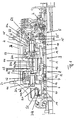
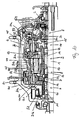
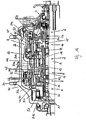
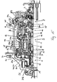
- Fig. 1 illustrates an embodiment of the hub transmission according to the invention that can be mounted to the rear wheel of a bicycle.
- the hub transmission comprises a hub axle 1 and a driver 2 which is rotatably supported by the hub axle 1.
- the hub transmission further comprises a hub shell 3 which is rotatably supported by the hub axle 1.
- a power transmission mechanism 4 is disposed between the driver 2 and the hub shell 3 for transmitting rotational power from the driver 2 to the hub shell 3 through a plurality of power transmission paths that can be selected to change the gear ratio as desired by the rider.
- To select one of the plurality of power transmission paths a shift mechanism 5 is provided.
- the shift mechanism 5 corresponds to the shift mechanism described in detail in EP 1 323 627 A2 and US 6,607,465 B1 mentioned therein.
- the power transmission mechanism 4 comprises a plurality of planetary gear mechanisms 6, 7, 8, 9, 10 including a downstream planetary gear mechanism and an upstream planetary gear mechanism wherein the upstream planetary gear mechanism is arranged closer to the driver 2 than the downstream planetary gear mechanism.
- the downstream planetary gear mechanism is arranged after the upstream planetary gear mechanism.
- the downstream planetary gear mechanism comprises the first and second planetary gear mechanisms 6, 7
- the upstream planetary gear mechanism comprises the third, fourth and fifth planetary gear mechanism 8, 9, 10.
- the first and second planetary gear mechanisms 6, 7 (downstream planetary gear mechanism) can be coupled with the fourth planetary gear mechanism 9 (upstream planetary gear mechanism).
- the plurality of planetary gear mechanisms 6, 7, 8, 9, 10 is arranged in series and comprises at least five planetary gear mechanisms 6, 7 ,8, 9, 10. The higher the number of the planetary gear mechanism 6, 7, 8, 9, 10 the closer it is arranged to the driver 2. For example, second planetary gear mechanism 7 is closer to the driver 2 than the first planetary gear mechanism 6.
- the downstream planetary gear mechanism comprises a planetary gear carrier 31, and the upstream planetary gear mechanism comprises planetary gears 44 wherein the planetary gear carrier 31 of the downstream or first and second planetary gear mechanisms 6, 7 meshes with planetary gears 44 of the upstream or fourth planetary gear mechanism 8.
- the planetary gear carrier 31 is a common carrier for both the first and second planetary gear mechanisms 6, 7.
- the planetary gear carrier 31 has a longitudinally extending shape that is adapted to overlap components of the power transmission mechanism 4 that are arranged upstream of the first and second planetary gear mechanisms 6, 7 and, thus, more proximate to the driver 2 than the downstream planetary gear mechanism 6, 7.
- the planetary gear carrier 31 of the downstream planetary gear mechanism 6, 7 axially extends from the area of the downstream or first and second planetary gear mechanisms 6, 7 to the area of the upstream or fourth planetary gear mechanism 9.
- the planetary gear carrier 31 axially extends over more than 1/3 to 1/2 of the entire length of the hub transmission.
- the axial extension of the planetary gear carrier 31 is such that the third planetary gear mechanism 8 which is arranged between the downstream planetary gear mechanisms 6, 7 and the upstream, in particular fourth planetary gear mechanism 9 is overlapped by the planetary gear carrier 31.
- the third planetary gear mechanism 8 is not engaged with the planetary gear carrier 31.
- the planetary gear carrier 31 comprises a stepped shape wherein the inner diameter of the subsequent steps increases towards the driver 2.
- the stepped shape of the planetary gear carrier 31 will be described in more detail in conjunction with the respective components associated thereto.
- the planetary gear carrier 31 further comprises a (first) clutch engaging portion 31 c which is arranged on the axial end of the planetary gear carrier 31 proximate to the driver 2.
- the clutch engaging portion 31 c is provided to engage with/disengage from a clutch 53 (third clutch) which will be described in more detail in connection with the fifth planetary gear mechanism 10.
- the planetary gear carrier 31 further comprises a ring gear portion 31b.
- the ring gear portion 31b is integrally connected with the clutch engaging portion 31c and is formed with a smaller inner diameter than clutch engaging portion 31 c.
- the ring gear portion 31b meshes with the planetary gears 44 of the upstream or fourth planetary gear mechanism 9.
- the inner diameter of the ring gear portion 31b is larger than the outer diameter of third planetary gears 43 of the third planetary gear mechanism 8, to avoid engagement or collision therewith.
- the ring gear portion 31 b is integrally connected with a carrier portion 31a which supports first planetary gears 41 of the first downstream planetary gear mechanism 6 and second planetary gears 42 of the second downstream planetary gear mechanism 7.
- the first planetary gears 41 are rotatably supported by first planetary gear shafts 41 a.
- the second planetary gears 42 are rotatably supported by second planetary gear shafts 42a.
- the first and second planetary gear shafts 41 a, 42a are disposed in a carrier portion 31a of the planetary gear carrier 31.
- three or more first planetary gears 41 respectively second planetary gears 42 are provided in the first respectively second planetary gear mechanism 6, 7.
- a further (or second) clutch engaging portion 31d is integrally formed with the carrier portion 31a and is provided for engaging with/disengaging from a first clutch 51 to establish/interrupt a power transmission from the planetary gear carrier 31 to the hub shell 3.
- the further (or second) clutch engaging portion 31d is arranged downstream of the first planetary gear mechanism 6.
- the ring gear portion 31b and the (first) clutch engaging portion 31c are located upstream of the planetary gear mechanism 6. Again, the downstream or upstream arrangement of components is seen and to be understood in the direction of the power flow.
- the plurality of planetary gear mechanisms 6, 7, 8, 9, 10 will be described in the following.
- the first planetary gear mechanism 6 is arranged most downstream or most distant from the driver 2 and comprises a first sun gear 11 which is rotatably supported by and lockable with the hub axle 1. Between an inner peripheral surface of the first sun gear 11 and the hub axle 1, a first sun gear guide ring 61 is non-rotatably fixed to the hub axle 1. The first sun gear guide ring 61 allows the locking and unlocking of the first sun gear 11 by means of the shifting mechanism 5.
- the plurality of first planetary gears 41 is rotatably supported by the first planetary gear carrier 31, in particular by first planetary gear shafts 41a disposed in the first planetary gear carrier 31, and meshes with the first sun gear 11.
- the second planetary gear mechanism 7 is arranged upstream of the first planetary gear mechanism 6 and comprises a second sun gear 12 which is rotatably supported by, and lockable with, the hub axle 1.
- the first sun gear 11 and the second sun gear 12 are arranged adjacent or next to each other.
- the first and second sun gears 11, 12 are lockable with the hub axle 1.
- the first sun gear 11 and the second sun gear 12 form part of the downstream planetary gear mechanism which is coupled with the planetary gears 44 of the upstream planetary gear mechanism or fourth planetary gear mechanism 9, by means of the first planetary gear carrier 31.
- the second sun gear 12 comprises an axial projection 12a which extends in a downstream axial direction.
- the axial projection 12a is arranged radially below the engaging portion of the first sun gear 11 which meshes with the first planetary gears 41.
- the sun gear 11 comprises a shoulder which accommodates the axial projection 12a of the second sun gear 12.
- the second planetary gear mechanism 7 further comprises the second planetary gears 42 which mesh with second sun gear 12, Coaxially arranged in relation to and rotatably supported by the hub axle 1, is a first ring gear 21 which meshes with second planetary gears 42 of the second planetary gear mechanism 7 such that the second planetary gears 42 are arranged in between the first ring gear 21 and the second sun gear 12.
- the second planetary gears 42 are supported by second planetary gear shafts 42a.
- the second planetary gear shafts 42a are disposed in the first planetary gear carrier 31.
- the second planetary gear shaft 42a is integrally formed with the first planetary gear shaft 41 a such that the first and second planetary gears 41, 42 are supported by the same or a common shaft 41 a, 42a.
- the first and second planetary gears 41, 42 form two gear stages wherein the large diameter gear stage of the first planetary gear 41 meshes with the first sun gear 11 and the small diameter gear stage of the second planetary gear 42 meshes with the first ring gear 21.
- the small diameter gear stage of the second planetary gears 42 is arranged proximate to the third planetary gear mechanism 8.
- the first and second planetary gears 41, 42 are non-rotatably coupled, in particular integrally formed.
- the first and second planetary gears 41, 42 constitute a stepped or non-rotatably coupled planetary gear comprising two different diameters, which mesh with the first and second sun gears 11, 12 (in general: with the at least two sun gears 11,12).
- the large diameter of the stepped planetary gear meshes with the first sun gear 11 and the small diameter of the stepped planetary gear meshes with the second sun gear 12 and the first ring gear 21.
- the at least two sun gears 11, 12 can be coupled by means of the first planetary gear carrier 31 with an upstream planetary gear mechanism, in particular with the fourth planetary gear mechanism 9.
- the first ring gear 21 can be connected with or disconnected from the hub shell 3 by means of a second (one-way) clutch 52 which is disposed between the first ring gear 21 and the hub shell 3.
- first planetary gear carrier 31 of the first planetary gear mechanism 6 extends axially beyond the first and second planetary gears 41, 42 in a longitudinal direction of the hub transmission thereby overlapping at least the subsequently arranged upstream third and fourth planetary gear mechanisms 8, 9.
- the outer contour of first planetary gear carrier 31 is adapted to partially accommodate the first ring gear 21 and forms a shoulder 31e such that the first ring gear 21 is arranged between the shoulder 31e and the large diameter gear stage of the first planetary gears 41.
- the third planetary gear mechanism 8 is located upstream of the second planetary gear mechanism 7 and comprises a third sun gear 13 which is rotatably supported by and lockable with the hub axle 1. Between an inner surface of the second sun gear 13 and the hub axle 1, a third sun gear guide ring 63 is non-rotatably fixed to the hub axle 1.
- a plurality of third planetary gears 43 is rotatably supported by a second planetary gear carrier 32 which is rotatably supported by the hub axle 1.
- the third planetary gears 43 are rotatably supported by third planetary gear shafts 43a which are supported by second planetary gear carrier 32.
- Typically three or more third planetary gears 43 are provided.
- the fourth planetary gear mechanism 8 is arranged upstream of the third planetary gear mechanism 8 and comprises a fourth sun gear 14 which is rotatably supported by, and lockable with, the hub axle 1. Between an inner peripheral surface of the fourth sun gear 13 and the hub axle 1, a fourth sun gear guide ring 64 is arranged and non-rotatably fixed to hub axle 1. The fourth sun gear guide ring 64 can be actuated by means of the shifting mechanism 5 to lock/unlock the fourth sun gear 14.
- a plurality of fourth planetary gears 44 meshes with the fourth sun gear 14 and is rotatably supported by the second planetary gear carrier 32.
- fourth planetary gears 44 are arranged on a fourth planetary gear shaft 44a which is integrally formed with the third planetary gear shaft 43a and, thus, represents a common planetary gear shaft for the third and fourth planetary gears 43, 44.
- third and fourth planetary gears 43, 44 are non-rotatably connected and integrally form a stepped planetary gear 402.
- the small diameter gear stage of the stepped planetary gear 402 (third planetary gears 43) meshes with the third sun gear 13, and the large diameter gear stage of the stepped planetary gear 402 (fourth planetary gears 44) meshes with the fourth sun gear 9.
- the large diameter gear stage of the stepped planetary gear 402 (fourth planetary gears 44) meshes with the ring gear portion 31b of the downstream planetary gear carrier 31.
- a fifth planetary gear mechanism 10 is arranged upstream of the fourth planetary gear mechanism 9 and represents the planetary gear mechanism closest to the driver 2.
- the fifth planetary gear mechanism 10 comprises a fifth sun gear 15 which is non-rotatably fixed to the hub axle 1.
- a second ring gear 22 is coaxially arranged with and rotatably supported by the hub axle 1.
- a plurality of fifth planetary gears 45 is arranged which are formed as two-step planetary gears.
- the large diameter gear stage of the fifth planetary gears 45 meshes with the second ring gear 22, and the small diameter gear stage of the fifth planetary gears 45 meshes with the fifth sun gear 15.
- Typically three or more fifth planetary gears 45 are provided.
- the fifth planetary gears 45 are rotatably supported by a third planetary gear carrier 33 which can rotate around the hub axle 1.
- the third planetary gear carrier 33 comprises fifth planetary gear shafts 45a which rotatably support the fifth planetary gears 45.
- the third planetary gear carrier 33 is engaged with the second planetary gear carrier 32 to transmit power from the third planetary gear carrier 33 to the second planetary gear carrier 32.
- the middle axes of the third and fourth planetary gear shafts 43a, 44a and the middle axes of the fifth planetary gear shafts 45a are radially spaced apart.
- the middle axes of fifth planetary gear shafts 45a are arranged on a cylindrical plane having a larger diameter than a cylindrical plane which comprises the middle axes of the third and fourth planetary gear shafts 43a, 44a.
- the cylindrical plane which comprises the middle axes of first and second planetary gear shafts 41 a, 42a corresponds to the cylindrical plane of the middle axes of the fifth planetary gear shafts 45a.
- the middle axes of the third and fourth planetary gear shafts 43a, 44a, which are arranged between the second and fifth planetary gear mechanisms 7 and 10, are closer to the hub axle 1 than the middle axes of the second and fifth planetary gear shafts 42a, 45a, respectively.
- the third planetary gear carrier 33 of the fifth planetary gear mechanism 9 can be connected to the downstream planetary gear carrier 31.
- the third clutch 53 mentioned above is provided between the third planetary gear carrier 33 and the first planetary gear carrier 31.
- the third clutch 53 is arranged at an end of the third planetary gear carrier 33 distant from the driver 2 and engages with/disengages from the clutch engaging portion 31c of downstream of the first planetary gear carrier 31.
- fourth and fifth clutches 54 and 55 are provided for the power transmission from the driver 2 to the fifth planetary gear mechanism 9.
- the fourth clutch 54 is a one-way clutch disposed between the driver 2 and the second ring gear 22.
- the second ring gear 22 comprises an axial projection 22a which extends towards the driver 2.
- the axial projection 22a comprises on its inner peripheral surface a clutch engaging portion 22b, which cooperates with the fourth clutch 54 to lock or unlock the second ring gear 22 with the driver 2.
- the fourth clutch 54 is supported by an axial projection 2a of the driver 2 that extends in parallel with the axial projection 22a of the ring gear 22.
- the fourth clutch 54 is engaged with the ring gear 22 to transmit power from the driver 2 to the ring gear 22.
- a fifth clutch 55 is provided which is disposed between the driver 2 and the third planetary gear carrier 33 for transmitting rotational power from the driver 2 to the third planetary gear driver 33.
- the fifth clutch 55 is formed as a clutch ring and is axially movable in a longitudinal direction of the hub axle 1.
- the fifth clutch 55 comprises two engaging portions 55a, 55b which are adapted to engage with clutch engaging portions 2b and 33a which are provided on the driver 2 and the third planetary gear carrier 33, respectively.
- the clutch engaging portion 2b of the driver 2 is formed on the inner peripheral surface of the axial projection 2a and engages with the upper or radial engaging portion 55b of the fifth clutch 55.
- the clutch engaging portion 33a of the third planetary gear carrier 33 is adapted to engage with/disengage from the lower or axial engaging portion 55a of the fifth clutch 55.
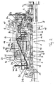
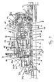
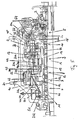
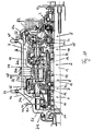
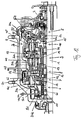
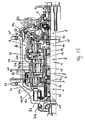
- FIG. 1 The function of the hub transmission according to Fig. 1 is explained with reference to Figures 2 to 16 in which the coupling of the various components for each speed stage and the specific power transmission path realized thereby are illustrated.
- the bold lines and arrows indicated in Figures 2 to 16 illustrate the rotational power flow through the power transmission mechanism 4.
- the coupling of the various components as well as the power transmission paths are indicated in the following Tables 1 and 2 wherein Table 1 concerns the coupling of the components and Table 2 concerns the specific power transmission path.
- the hub transmission according to the described embodiment of the invention allows the realization of an 11 speed internal hub transmission wherein the diameter of the hub shell 2 is similar to the diameter of a currently available 8 speed hub transmission.
- the hub transmission of the invention provides more speed stages than the conventional hub transmission without increasing the hub diameter.
- the hub transmission according to Fig. 1 provides the advantage that all transmission paths are simple which leads to an efficient power transmission.
- the planetary gear carrier 31 of the downstream planetary gear mechanism 6 has an axially elongated shape adapted to mesh with the planetary gears 43 of the upstream planetary gear mechanism 8.
- the axially elongated shape of the planetary gear carrier 31 allows for coupling/uncoupling the planetary gear carrier 31 with/from a planetary gear carrier 33 of a further upstream planetary gear mechanism 9.
- the axially elongated planetary gear carrier 31 of the downstream planetary gear mechanism 6 is adapted to selectively transmit rotational power from the planetary gears 43 of an upstream planetary gear mechanism 8 and to selectively transmit rotational power from the planetary gear carrier 33 of the further upstream planetary gear mechanism 9.
- the axially elongated shape of the downstream planetary gear carrier 31 allows for a compact, small diameter internal hub transmission for a bicycle with highly efficient transmission paths.
Landscapes
- Engineering & Computer Science (AREA)
- Chemical & Material Sciences (AREA)
- Combustion & Propulsion (AREA)
- Transportation (AREA)
- Mechanical Engineering (AREA)
- Structure Of Transmissions (AREA)
Claims (19)
- Nabenschaltung für ein Fahrrad, wobei die Nabenschaltung folgendes aufweist:- eine Nabenachse (1);- ein Antriebselement (2), das von der Nabenachse (1) drehbar gelagert ist;- ein Nabengehäuse (3), das von der Nabenachse (1) drehbar gelagert ist;- einen Kraftübertragungsmechanismus (4), der zwischen dem Antriebselement (2) und dem Nabengehäuse (3) angeordnet ist, um Rotationskraft von dem Antriebselement (2) über eine Vielzahl von Kraftübertragungswegen auf das Nabengehäuse (3) zu übertragen; und- einen Schaltmechanismus (5) zum Auswählen von einem aus der Vielzahl von Kraftübertragungswegen;wobei der Kraftübertragungsmechanismus (4) eine Vielzahl von Planetengetrieben (6, 7, 8, 9, 10) aufweist und ein Planetenradträger (31) eines nachgeschalteten Planetengetriebes mit Planetenrädern (44) eines vorgeschalteten Planetengetriebes kämmt,
dadurch gekennzeichnet,
daß das nachgeschaltete Planetengetriebe mehr als ein Sonnenrad aufweist. - Nabenschaltung nach Anspruch 1,
wobei der Kraftübertragungsmechanismus (4) mindestens fünf Planetengetriebe (6, 7, 8, 9, 10) aufweist, die in Reihe angeordnet sind. - Nabenschaltung nach Anspruch 1 oder 2,
wobei das nachgeschaltete Planetengetriebe mindestens ein erstes und ein zweites Planetengetriebe (6, 7) aufweist und das vorgeschaltete Planetengetriebe mindestens ein drittes, ein viertes und ein fünftes Planetengetriebe (8, 9, 10) aufweist. - Nabenschaltung nach Anspruch 3,
wobei das erste und das zweite Planetengetriebe (6, 7) den Planetenradträger (31) des nachgeschalteten Planetengetriebes aufweisen und das vierte Planetengetriebe (9) die Planetenräder (44) des vorgeschalteten Planetengetriebes aufweist. - Nabenschaltung nach einem der Ansprüche 1 bis 4,
wobei der Planetenradträger (31) des nachgeschalteten Planetengetriebes einen Trägerbereich (31a) und einen Hohlradbereich (31b) aufweist, der mit den Planetenrädern (44) des vorgeschalteten Planetengetriebes kämmt, wobei der Trägerbereich (31a) und der Hohlradbereich (31b) drehfest miteinander verbunden, insbesondere integral ausgebildet sind. - Nabenschaltung nach einem der Ansprüche 3 bis 5,
wobei der Planetenradträger (31) mit dem fünften Planetengetriebe (10) verbindbar ist. - Nabenschaltung nach einem Anspruch 6,
wobei der Planetenradträger (31) einen Kupplungseingriffsbereich (31c) aufweist, der mit einem Planetenradträger (33) des fünften Planetengetriebes (10) verbindbar ist. - Nabenschaltung nach einem der Ansprüche 1 bis 7,
wobei der Planetenradträger (31) mit dem Nabengehäuse (3) mittels einer ersten Kupplung (51) verbindbar ist, um eine Rotationskraft von dem Planetenradträger (31) auf das Nabengehäuse (3) zu übertragen. - Nabenschaltung nach einem der Ansprüche 3 bis 8,
wobei das erste Planetengetriebe (6) ein erstes Sonnenrad (11), das von der Nabenachse (1) drehbar gelagert und mit dieser verriegelbar ist, sowie eine Vielzahl von ersten Planetenrädern (41) aufweist, die mit dem ersten Sonnenrad (11) kämmen, wobei die ersten Planetenräder (41) von dem Planetenradträger (31) des ersten Planetengetriebes (6) drehbar gelagert sind. - Nabenschaltung nach einem der Ansprüche 3 bis 9,
wobei das zweite Planetengetriebe (7) ein zweites Sonnenrad (12), das von der Nabenachse (1) drehbar gelagert und mit dieser verriegelbar ist, ein erstes Hohlrad (21), das mit dem zweiten Sonnerad (12) koaxial angeordnet ist, sowie eine Vielzahl von zweiten Planetenrädern (42) aufweist, die mit dem zweiten Sonnenrad (12) und dem ersten Hohlrad (21) kämmen, wobei die zweiten Planetenräder (31) von dem Planetenradträger (31) des ersten Planetengetriebes (6) drehbar gelagert sind und die ersten und zweiten Planetenräder (41, 42) drehfest miteinander verbunden, insbesondere integral ausgebildet sind und dadurch jeweils stufige Planetenräder bilden. - Nabenschaltung nach Anspruch 10,
wobei das erste Hohlrad (21) mit dem Nabengehäuse (3) durch eine zweite Kupplung (52) verbindbar ist, um eine Rotationskraft von dem ersten Hohlrad (21) auf das Nabengehäuse (3) zu übertragen. - Nabenschaltung nach einem der Ansprüche 3 bis 11,
wobei das dritte Planetengetriebe (8) ein drittes Sonnerad (13), das von der Nabenachse (1) drehbar gelagert und mit dieser verriegelbar ist, einen zweiten Planetenradträger (32), der relativ zu der Nabenachse (1) drehbar gelagert ist, sowie eine Vielzahl von dritten Planetenrädern (43) aufweist, die von dem zweiten Planetenradträger (32) drehbar gelagert sind und mit dem dritten Sonnenrad (13) kämmen. - Nabenschaltung nach einem der Ansprüche 3 bis 12,
wobei das vierte Planetengetriebe (9) ein viertes Sonnenrad (14) aufweist, das von der Nabenachse (1) drehbar gelagert und mit dieser verriegelbar ist, wobei die Planetenräder (44) des vorgeschalteten Planetengetriebes, insbesondere des vierten Planetengetriebes (9), von dem zweiten Planetenradträger (32) drehbar gelagert sind und mit dem vierten Sonnenrad (14) kämmen. - Nabenschaltung nach Anspruch 13,
wobei die Planetenräder (44) des vierten Planetengetriebes (9) und die dritten Planetenräder (43) des dritten Planetengetriebes (8) drehfest miteinander verbunden, insbesondere integral ausgebildet sind und dadurch jeweils stufige Planetenräder (402) bilden. - Nabenschaltung nach einem der Ansprüche 3 bis 14,
wobei das fünfte Planetengetriebe (10) ein fünftes Sonnenrad (15), das auf der Nabenachse (11) drehfest festgelegt ist, ein zweites Hohlrad (22), das mit dem fünften Sonnenrad (14) koaxial angeordnet ist, und eine Vielzahl von fünften Planetenrädern (45) aufweist, die von einem dritten Planetenradträger (33) drehbar gelagert sind, wobei die fünften Planetenräder (45) mit dem fünften Sonnenrad (15) und dem zweiten Hohlrad (22) kämmen. - Nabenschaltung nach Anspruch 15,
wobei der dritte Planetenradträger (33) mit dem zweiten Planetenradträger (32) in Eingriff tritt. - Nabenschaltung nach Anspruch 15 oder 16,
wobei eine dritte Kupplung (53) zwischen dem dritten Planetenradträger (33) und dem ersten Planetenradträger (31), insbesondere dem Kupplungseingriffsbereich (31 c), angeordnet ist, um eine Rotationskraft von dem dritten Planetenradträger (33) auf den ersten Planetenradträger (31) zu übertragen. - Nabenschaltung nach einem der Ansprüche 12 bis 17,
wobei eine vierte Kupplung (54) zwischen dem Antriebselement (2) und dem zweiten Hohlrad (22) angeordnet ist, um eine Rotationskraft von dem Antriebselement (2) auf das zweite Hohlrad (22) zu übertragen. - Nabenschaltung nach einem der Ansprüche 13 bis 18,
wobei eine fünfte Kupplung (55) zwischen dem Antriebselement (2) und dem dritten Planetenradträger (33) angeordnet ist, um eine Rotationskraft von dem Antriebselement (2) auf den dritten Planetenradträger (33) zu übertragen.
Priority Applications (6)
| Application Number | Priority Date | Filing Date | Title |
|---|---|---|---|
| DE602007006943T DE602007006943D1 (de) | 2007-08-01 | 2007-08-01 | Nabenschaltung für ein Fahrrad |
| EP07015124.6A EP2020375B2 (de) | 2007-08-01 | 2007-08-01 | Nabenschaltung für ein Fahrrad |
| TW097101383A TWI361781B (en) | 2007-08-01 | 2008-01-14 | Hub transmission for a bicycle |
| CN2008100810893A CN101357669B (zh) | 2007-08-01 | 2008-02-26 | 用于自行车的轮毂传动装置 |
| US12/103,096 US7887455B2 (en) | 2007-08-01 | 2008-04-15 | Bicycle hub transmission |
| JP2008190136A JP4726932B2 (ja) | 2007-08-01 | 2008-07-23 | 自転車用内装変速ハブ |
Applications Claiming Priority (1)
| Application Number | Priority Date | Filing Date | Title |
|---|---|---|---|
| EP07015124.6A EP2020375B2 (de) | 2007-08-01 | 2007-08-01 | Nabenschaltung für ein Fahrrad |
Publications (3)
| Publication Number | Publication Date |
|---|---|
| EP2020375A1 EP2020375A1 (de) | 2009-02-04 |
| EP2020375B1 true EP2020375B1 (de) | 2010-06-02 |
| EP2020375B2 EP2020375B2 (de) | 2014-09-24 |
Family
ID=38432897
Family Applications (1)
| Application Number | Title | Priority Date | Filing Date |
|---|---|---|---|
| EP07015124.6A Active EP2020375B2 (de) | 2007-08-01 | 2007-08-01 | Nabenschaltung für ein Fahrrad |
Country Status (6)
| Country | Link |
|---|---|
| US (1) | US7887455B2 (de) |
| EP (1) | EP2020375B2 (de) |
| JP (1) | JP4726932B2 (de) |
| CN (1) | CN101357669B (de) |
| DE (1) | DE602007006943D1 (de) |
| TW (1) | TWI361781B (de) |
Families Citing this family (16)
| Publication number | Priority date | Publication date | Assignee | Title |
|---|---|---|---|---|
| KR20080003165A (ko) * | 2006-06-30 | 2008-01-07 | 변동환 | 유성 기어식 변속기와 그것을 이용한 차량 |
| EP2008927B1 (de) * | 2007-06-29 | 2010-01-13 | Shimano Inc. | Nabenschaltung für ein Fahrrad |
| US20120172171A1 (en) * | 2009-05-26 | 2012-07-05 | Donghwan Byun | Multistage transmission |
| EP2256368B1 (de) * | 2009-05-27 | 2015-07-08 | Sun Race Sturmey-Archer Inc. | Mechanismus zur Geschwindigkeitsänderung |
| CN101997361B (zh) * | 2009-08-10 | 2014-05-14 | 日驰企业股份有限公司 | 马达变速机构 |
| US8226517B2 (en) | 2009-08-10 | 2012-07-24 | Sun Race Sturmey-Archer, Inc. | Speed change mechanism |
| DE102009056206A1 (de) * | 2009-11-28 | 2011-06-01 | Sram Deutschland Gmbh | Mehrgang-Getriebenabe für Fahrräder |
| US8439792B2 (en) * | 2010-01-20 | 2013-05-14 | The Gates Corporation | Planetary gear mechanism for a bicycle |
| EP2744699A1 (de) * | 2011-08-17 | 2014-06-25 | Synergy Biosurgical AG | Vorrichtung zum antreiben und exzentrischen bremsen eines fahrzeugs |
| US9005068B2 (en) * | 2012-12-21 | 2015-04-14 | Shimano Inc. | Continuously variable bicycle transmission mechanism and bicycle hub |
| JP6302870B2 (ja) * | 2015-05-29 | 2018-03-28 | 株式会社シマノ | 変速機 |
| DE102018212433A1 (de) | 2018-07-25 | 2020-01-30 | Robert Bosch Gmbh | Betriebsverfahren für eine Antriebsanordnung, Antriebsanordnung und Fahrzeug |
| NO345740B1 (en) * | 2018-12-21 | 2021-07-12 | Ca Tech Systems As | Clutch and multispeed gear |
| JP7337586B2 (ja) * | 2019-07-31 | 2023-09-04 | 株式会社シマノ | 人力駆動車用の変速装置およびこの変速装置を備える人力駆動車用のアシストシステム |
| CN112406519A (zh) * | 2020-12-02 | 2021-02-26 | 上海振华重工电气有限公司 | 一种用于轮胎吊的永磁同步电机驱动机构及轮胎式起重机 |
| CN117489761A (zh) * | 2023-09-09 | 2024-02-02 | 广东洛梵狄智能科技有限公司 | 一种固定机构、中轴变速器及中置电机 |
Family Cites Families (16)
| Publication number | Priority date | Publication date | Assignee | Title |
|---|---|---|---|---|
| GB738338A (en) * | 1953-05-09 | 1955-10-12 | Sturmey Archer Gears Ltd | Improvements in or relating to epicyclic change speed gears |
| JP3184230B2 (ja) * | 1990-12-28 | 2001-07-09 | 株式会社シマノ | 内装変速機 |
| DE4342347C1 (de) * | 1993-12-11 | 1995-02-09 | Fichtel & Sachs Ag | Mehrgangnabe für Fahrräder |
| DE19745419A1 (de) | 1996-10-16 | 1998-04-23 | Schievelbusch Ulrich Univ Prof | Mehrgang-Getriebenabe |
| DE19720796B4 (de) * | 1997-05-16 | 2005-10-20 | Bernhard Rohloff | Mehrgang-Getriebenabe für Fahrräder |
| DE19720794A1 (de) † | 1997-05-16 | 1998-11-19 | Bernhard Rohloff | Mehrgang-Getriebenabe |
| GB2355772A (en) * | 1999-10-30 | 2001-05-02 | Adrian Ash | Bicycle gearbox having a plurality of planetary gear sets in series |
| US6607465B1 (en) * | 2000-03-10 | 2003-08-19 | Shimano, Inc. | Bicycle hub transmission with a guiding member for a sun gear |
| GB0012873D0 (en) † | 2000-05-27 | 2000-07-19 | Sturmey Archer Ltd | A multi speed hub gear |
| DE10115986A1 (de) * | 2001-03-30 | 2002-10-10 | Zahnradfabrik Friedrichshafen | Mehrstufengetriebe |
| US6875150B2 (en) * | 2001-12-27 | 2005-04-05 | Shimano, Inc. | Multiple piece planet gear carrier for a bicycle hub transmission |
| US6641500B2 (en) * | 2001-12-27 | 2003-11-04 | Shimano, Inc. | Bicycle hub transmission with a power control mechanism for a shift assist mechanism |
| EP1344714B2 (de) * | 2002-03-14 | 2014-04-16 | Shimano Inc. | Fahrradantriebsnabe |
| DE102004011052A1 (de) † | 2004-03-06 | 2005-09-22 | Sram Deutschland Gmbh | Fahrradnabe mit Planetengetriebe |
| DE102006006645A1 (de) * | 2006-02-14 | 2007-08-23 | Zf Friedrichshafen Ag | Mehrstufengetriebe |
| DE602007011028D1 (de) † | 2007-01-18 | 2011-01-20 | Shimano Kk | Antriebsnabe für ein Fahrrad und Verfahren zum Schalten einer derartigen Antriebsnabe |
-
2007
- 2007-08-01 EP EP07015124.6A patent/EP2020375B2/de active Active
- 2007-08-01 DE DE602007006943T patent/DE602007006943D1/de active Active
-
2008
- 2008-01-14 TW TW097101383A patent/TWI361781B/zh active
- 2008-02-26 CN CN2008100810893A patent/CN101357669B/zh active Active
- 2008-04-15 US US12/103,096 patent/US7887455B2/en not_active Expired - Fee Related
- 2008-07-23 JP JP2008190136A patent/JP4726932B2/ja not_active Expired - Fee Related
Also Published As
| Publication number | Publication date |
|---|---|
| EP2020375A1 (de) | 2009-02-04 |
| DE602007006943D1 (de) | 2010-07-15 |
| CN101357669A (zh) | 2009-02-04 |
| TWI361781B (en) | 2012-04-11 |
| TW200911619A (en) | 2009-03-16 |
| EP2020375B2 (de) | 2014-09-24 |
| CN101357669B (zh) | 2012-06-13 |
| US7887455B2 (en) | 2011-02-15 |
| JP2009035249A (ja) | 2009-02-19 |
| JP4726932B2 (ja) | 2011-07-20 |
| US20090036262A1 (en) | 2009-02-05 |
Similar Documents
| Publication | Publication Date | Title |
|---|---|---|
| EP2020375B1 (de) | Nabenschaltung für ein Fahrrad | |
| EP2017175B1 (de) | Nabenschaltung für ein Fahrrad | |
| EP2008927B1 (de) | Nabenschaltung für ein Fahrrad | |
| EP1958866B1 (de) | Mehrgang-fahrradnaben-getriebeanordnung | |
| EP1947003B1 (de) | Antriebsnabe für ein Fahrrad und Verfahren zum Schalten einer derartigen Antriebsnabe | |
| US7678012B2 (en) | Bicycle hub gearbox | |
| US20110130242A1 (en) | Multi-Speed Internal Gear Hub for a Bicycle | |
| US7192379B2 (en) | Planetary gear mechanism for a bicycle hub | |
| CN102155521A (zh) | 行星齿轮机构和包括该行星齿轮机构的机械变速器 | |
| US7935019B2 (en) | Bicycle hub transmission | |
| JP2003534981A (ja) | 多段速度ハブギア | |
| CN201802825U (zh) | 行星齿轮机构和包括该行星齿轮机构的机械变速器 | |
| WO2011097780A1 (zh) | 行星齿轮机构和包括该行星齿轮机构的机械变速器 |
Legal Events
| Date | Code | Title | Description |
|---|---|---|---|
| PUAI | Public reference made under article 153(3) epc to a published international application that has entered the european phase |
Free format text: ORIGINAL CODE: 0009012 |
|
| AK | Designated contracting states |
Kind code of ref document: A1 Designated state(s): AT BE BG CH CY CZ DE DK EE ES FI FR GB GR HU IE IS IT LI LT LU LV MC MT NL PL PT RO SE SI SK TR |
|
| AX | Request for extension of the european patent |
Extension state: AL BA HR MK RS |
|
| 17P | Request for examination filed |
Effective date: 20090403 |
|
| 17Q | First examination report despatched |
Effective date: 20090507 |
|
| AKX | Designation fees paid |
Designated state(s): DE NL |
|
| GRAP | Despatch of communication of intention to grant a patent |
Free format text: ORIGINAL CODE: EPIDOSNIGR1 |
|
| GRAS | Grant fee paid |
Free format text: ORIGINAL CODE: EPIDOSNIGR3 |
|
| GRAA | (expected) grant |
Free format text: ORIGINAL CODE: 0009210 |
|
| AK | Designated contracting states |
Kind code of ref document: B1 Designated state(s): DE NL |
|
| REF | Corresponds to: |
Ref document number: 602007006943 Country of ref document: DE Date of ref document: 20100715 Kind code of ref document: P |
|
| REG | Reference to a national code |
Ref country code: NL Ref legal event code: T3 |
|
| PLBI | Opposition filed |
Free format text: ORIGINAL CODE: 0009260 |
|
| PLAX | Notice of opposition and request to file observation + time limit sent |
Free format text: ORIGINAL CODE: EPIDOSNOBS2 |
|
| 26 | Opposition filed |
Opponent name: SRAM DEUTSCHLAND GMBH Effective date: 20110223 |
|
| PLAB | Opposition data, opponent's data or that of the opponent's representative modified |
Free format text: ORIGINAL CODE: 0009299OPPO |
|
| R26 | Opposition filed (corrected) |
Opponent name: SRAM DEUTSCHLAND GMBH Effective date: 20110223 |
|
| REG | Reference to a national code |
Ref country code: DE Ref legal event code: R026 Ref document number: 602007006943 Country of ref document: DE Effective date: 20110223 |
|
| PLAF | Information modified related to communication of a notice of opposition and request to file observations + time limit |
Free format text: ORIGINAL CODE: EPIDOSCOBS2 |
|
| PLBB | Reply of patent proprietor to notice(s) of opposition received |
Free format text: ORIGINAL CODE: EPIDOSNOBS3 |
|
| PUAH | Patent maintained in amended form |
Free format text: ORIGINAL CODE: 0009272 |
|
| STAA | Information on the status of an ep patent application or granted ep patent |
Free format text: STATUS: PATENT MAINTAINED AS AMENDED |
|
| 27A | Patent maintained in amended form |
Effective date: 20140924 |
|
| AK | Designated contracting states |
Kind code of ref document: B2 Designated state(s): DE NL |
|
| REG | Reference to a national code |
Ref country code: DE Ref legal event code: R102 Ref document number: 602007006943 Country of ref document: DE |
|
| REG | Reference to a national code |
Ref country code: DE Ref legal event code: R102 Ref document number: 602007006943 Country of ref document: DE Effective date: 20140924 |
|
| REG | Reference to a national code |
Ref country code: NL Ref legal event code: T3 |
|
| PGFP | Annual fee paid to national office [announced via postgrant information from national office to epo] |
Ref country code: NL Payment date: 20160711 Year of fee payment: 10 |
|
| REG | Reference to a national code |
Ref country code: NL Ref legal event code: MM Effective date: 20170901 |
|
| PG25 | Lapsed in a contracting state [announced via postgrant information from national office to epo] |
Ref country code: NL Free format text: LAPSE BECAUSE OF NON-PAYMENT OF DUE FEES Effective date: 20170901 |
|
| P01 | Opt-out of the competence of the unified patent court (upc) registered |
Effective date: 20230428 |
|
| PGFP | Annual fee paid to national office [announced via postgrant information from national office to epo] |
Ref country code: DE Payment date: 20250702 Year of fee payment: 19 |