EP2019610B1 - Mattress with non-quilted panel - Google Patents
Mattress with non-quilted panel Download PDFInfo
- Publication number
- EP2019610B1 EP2019610B1 EP07794490.8A EP07794490A EP2019610B1 EP 2019610 B1 EP2019610 B1 EP 2019610B1 EP 07794490 A EP07794490 A EP 07794490A EP 2019610 B1 EP2019610 B1 EP 2019610B1
- Authority
- EP
- European Patent Office
- Prior art keywords
- mattress
- layer
- panel
- fabric
- edge
- Prior art date
- Legal status (The legal status is an assumption and is not a legal conclusion. Google has not performed a legal analysis and makes no representation as to the accuracy of the status listed.)
- Active
Links
- 239000000463 material Substances 0.000 claims description 53
- 239000004744 fabric Substances 0.000 claims description 41
- 239000000945 filler Substances 0.000 claims description 39
- 238000000034 method Methods 0.000 claims description 21
- 230000009970 fire resistant effect Effects 0.000 claims description 19
- 239000006260 foam Substances 0.000 claims description 19
- 238000004519 manufacturing process Methods 0.000 claims description 16
- 238000005304 joining Methods 0.000 claims description 9
- 239000003063 flame retardant Substances 0.000 claims description 8
- 238000009958 sewing Methods 0.000 claims description 7
- 229920000742 Cotton Polymers 0.000 claims description 4
- 229920000271 Kevlar® Polymers 0.000 claims description 3
- 238000005520 cutting process Methods 0.000 claims description 3
- 239000004816 latex Substances 0.000 claims description 2
- 229920000126 latex Polymers 0.000 claims description 2
- 229920002635 polyurethane Polymers 0.000 claims description 2
- 239000004814 polyurethane Substances 0.000 claims description 2
- 238000004026 adhesive bonding Methods 0.000 claims 1
- 238000002844 melting Methods 0.000 claims 1
- 230000008018 melting Effects 0.000 claims 1
- 239000012815 thermoplastic material Substances 0.000 claims 1
- 239000000835 fiber Substances 0.000 description 13
- 239000000853 adhesive Substances 0.000 description 6
- 230000001070 adhesive effect Effects 0.000 description 6
- 230000002093 peripheral effect Effects 0.000 description 6
- 230000004888 barrier function Effects 0.000 description 5
- 238000010276 construction Methods 0.000 description 4
- 229920000728 polyester Polymers 0.000 description 4
- IJGRMHOSHXDMSA-UHFFFAOYSA-N Atomic nitrogen Chemical compound N#N IJGRMHOSHXDMSA-UHFFFAOYSA-N 0.000 description 2
- 239000011230 binding agent Substances 0.000 description 2
- 230000000694 effects Effects 0.000 description 2
- 239000004761 kevlar Substances 0.000 description 2
- -1 linen Polymers 0.000 description 2
- 239000000203 mixture Substances 0.000 description 2
- 239000004033 plastic Substances 0.000 description 2
- 229920003023 plastic Polymers 0.000 description 2
- 239000012209 synthetic fiber Substances 0.000 description 2
- 229920002994 synthetic fiber Polymers 0.000 description 2
- XLYOFNOQVPJJNP-UHFFFAOYSA-N water Substances O XLYOFNOQVPJJNP-UHFFFAOYSA-N 0.000 description 2
- WKBOTKDWSSQWDR-UHFFFAOYSA-N Bromine atom Chemical compound [Br] WKBOTKDWSSQWDR-UHFFFAOYSA-N 0.000 description 1
- ZAMOUSCENKQFHK-UHFFFAOYSA-N Chlorine atom Chemical compound [Cl] ZAMOUSCENKQFHK-UHFFFAOYSA-N 0.000 description 1
- 229920000784 Nomex Polymers 0.000 description 1
- 239000004743 Polypropylene Substances 0.000 description 1
- 230000009471 action Effects 0.000 description 1
- 229910052782 aluminium Inorganic materials 0.000 description 1
- XAGFODPZIPBFFR-UHFFFAOYSA-N aluminium Chemical compound [Al] XAGFODPZIPBFFR-UHFFFAOYSA-N 0.000 description 1
- 230000000903 blocking effect Effects 0.000 description 1
- GDTBXPJZTBHREO-UHFFFAOYSA-N bromine Substances BrBr GDTBXPJZTBHREO-UHFFFAOYSA-N 0.000 description 1
- 229910052794 bromium Inorganic materials 0.000 description 1
- 229910052801 chlorine Inorganic materials 0.000 description 1
- 239000000460 chlorine Substances 0.000 description 1
- 150000001875 compounds Chemical class 0.000 description 1
- 238000007796 conventional method Methods 0.000 description 1
- 239000011152 fibreglass Substances 0.000 description 1
- 229910010272 inorganic material Inorganic materials 0.000 description 1
- 239000011147 inorganic material Substances 0.000 description 1
- 230000007257 malfunction Effects 0.000 description 1
- 229910052751 metal Inorganic materials 0.000 description 1
- 239000002184 metal Substances 0.000 description 1
- 238000002156 mixing Methods 0.000 description 1
- 238000012986 modification Methods 0.000 description 1
- 230000004048 modification Effects 0.000 description 1
- 229910052757 nitrogen Inorganic materials 0.000 description 1
- 239000004763 nomex Substances 0.000 description 1
- 239000011368 organic material Substances 0.000 description 1
- 239000002985 plastic film Substances 0.000 description 1
- 229920006255 plastic film Polymers 0.000 description 1
- 229920001155 polypropylene Polymers 0.000 description 1
- 230000008569 process Effects 0.000 description 1
- 239000012858 resilient material Substances 0.000 description 1
- 238000004513 sizing Methods 0.000 description 1
- 239000002699 waste material Substances 0.000 description 1
- 238000005303 weighing Methods 0.000 description 1
Images


Classifications
-
- A—HUMAN NECESSITIES
- A47—FURNITURE; DOMESTIC ARTICLES OR APPLIANCES; COFFEE MILLS; SPICE MILLS; SUCTION CLEANERS IN GENERAL
- A47C—CHAIRS; SOFAS; BEDS
- A47C31/00—Details or accessories for chairs, beds, or the like, not provided for in other groups of this subclass, e.g. upholstery fasteners, mattress protectors, stretching devices for mattress nets
- A47C31/001—Fireproof means
-
- A—HUMAN NECESSITIES
- A47—FURNITURE; DOMESTIC ARTICLES OR APPLIANCES; COFFEE MILLS; SPICE MILLS; SUCTION CLEANERS IN GENERAL
- A47C—CHAIRS; SOFAS; BEDS
- A47C27/00—Spring, stuffed or fluid mattresses or cushions specially adapted for chairs, beds or sofas
- A47C27/002—Mattress or cushion tickings or covers
-
- A—HUMAN NECESSITIES
- A47—FURNITURE; DOMESTIC ARTICLES OR APPLIANCES; COFFEE MILLS; SPICE MILLS; SUCTION CLEANERS IN GENERAL
- A47C—CHAIRS; SOFAS; BEDS
- A47C27/00—Spring, stuffed or fluid mattresses or cushions specially adapted for chairs, beds or sofas
- A47C27/001—Spring, stuffed or fluid mattresses or cushions specially adapted for chairs, beds or sofas with several cushions, mattresses or the like, to be put together in one cover
-
- A—HUMAN NECESSITIES
- A47—FURNITURE; DOMESTIC ARTICLES OR APPLIANCES; COFFEE MILLS; SPICE MILLS; SUCTION CLEANERS IN GENERAL
- A47C—CHAIRS; SOFAS; BEDS
- A47C27/00—Spring, stuffed or fluid mattresses or cushions specially adapted for chairs, beds or sofas
- A47C27/04—Spring, stuffed or fluid mattresses or cushions specially adapted for chairs, beds or sofas with spring inlays
-
- A—HUMAN NECESSITIES
- A47—FURNITURE; DOMESTIC ARTICLES OR APPLIANCES; COFFEE MILLS; SPICE MILLS; SUCTION CLEANERS IN GENERAL
- A47C—CHAIRS; SOFAS; BEDS
- A47C27/00—Spring, stuffed or fluid mattresses or cushions specially adapted for chairs, beds or sofas
- A47C27/14—Spring, stuffed or fluid mattresses or cushions specially adapted for chairs, beds or sofas with foamed material inlays
- A47C27/20—Spring, stuffed or fluid mattresses or cushions specially adapted for chairs, beds or sofas with foamed material inlays with springs moulded in, or situated in cavities or openings in foamed material
Definitions
- Mattress manufacture typically employs the covering of a resilient spring interior with a fabric cover that provides much of the comfort and the appearance of the mattress product.
- fabric covers are commonly made of quilted material formed by stitching patterns on multiple layered fabrics formed of a layer of backing material, one or more layers of thick filler material and an outer layer of facing material or ticking.
- the quilted fabric covers are most often formed on needle sewing machines that stitch the layers of material together with stitched patterns that contribute to the ornamental features of the mattress product.
- the layers of material become compressed along the lines of thread stitched into the layers.
- the contrast between the uncompressed layers of material and the indented stitch lines form an uneven surface on the mattress fabric cover.
- the quilting operation by the sewing machines also provides the functional joining of the material that forms the quilted mattress cover.
- the sewing machines are generally reliable, the needles of the sewing machines repeated travel through several layers of material to sew the layers together and may break with use. This may damage, not only the sewing machine, but also the materials being quilted together.
- a sewing machine may malfunction while stitching in various ways, such as mechanically jamming due to fabric or thread accidentally catching a moving part.
- US 1,205,135 discloses a mattress, comprising a mattress core having an upper primary surface, a mattress panel lying on the upper primary surface of the mattress and having a substantially smooth top surface, the panel having a fabric layer, a filler layer and a backing layer wherein the fabric layer, filler layer, and backing layer are joined at a respective edge
- a mattress core having an upper primary surface
- a mattress panel lying on the upper primary surface of the mattress and having a substantially smooth top surface
- the panel having a fabric layer, a filler layer and a backing layer wherein the fabric layer, filler layer, and backing layer are joined at a respective edge
- the present invention provides a mattress according to the characterising portion of claim 1, and a method of manufacturing a mattress panel according to the characterising portion of claim 10.
- the systems and methods described herein include improved mattresses and improved fabric covers for providing mattresses that have smooth surfaces. Additionally, the invention encompasses methods for manufacturing non-quilted mattress covers and for manufacturing mattresses employing non-quilted mattress covers.
- the systems and methods described herein include mattress panels that can be manufactured separate from the inner core construction, and laid over the inner core to be fastened in place as a sleeping surface for the mattress.
- these mattress panels can include a layer of fire retardant material, that may be added as a layer of material or that may be incorporated into one or more of the layers, such as a filler layer, in the mattress panel.
- FIGS. 1-5 illustrate various embodiments of the invention.
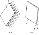
- Fig. 1A shows several layers of material prior to assembly into a mattress panel.
- the fabric layer 10 is the top layer and may be any desired sheet of material, such as cotton, linen, synthetic fibers or a mixture thereof.
- the top layer 10 may be a flat sheet of fabric or may be a substantially flat sheet with an angled lip of fabric (not shown) formed at each edge of the top layer 10.
- a lip may be formed by cutting out a wedge of fabric from each corner of the top layer 10 which border the edge and joining the cut sections of the top layer 10 together.
- the lip may be from about 0.5 inches to about 7 inches in length.
- the filler layer 20 is the cushioning layer and is formed from foam, latex, visco elastic foam.
- the filler layer 20 may be from about 0.25 inches to about 5 inches in height, preferably from about 1 inch to about 4 inches.
- the filler layer may be a foam substantially 3 inches in height with an ILD of 12 and a density of 1.2.
- the ILD may be different from this preferred embodiment and the density and ILD can vary according to the application.
- the density can range from about 1.0 to about 5.0 and the ILD can vary from, for example, about 10 to about 40 ILD. Other values may also be used without departing from the scope of the invention.
- the filler layer 20 may have a substantially flat, smooth upper surface or may have a textured or patterned upper surface. According to the invention the center section of the filler layer has a uniform height and decrease at a uniform angle toward its edges.
- the filler layer 20 may have multiple zones, including a lumbar zone and a shoulder zone.
- the panel has a foam filler layer 20 that includes a layer of gel material that is formed within the foam layer and that extends from one side of the mattress to the other side, providing a zone of gel material at an area where the lumbar of a sleeping user would be positioned. The number of zones and the location of the zones may vary according to the application.
- a fire resistant layer 24 may be placed between the filler layer 20 and the fabric layer 10.
- the fire resistant layer 24 includes a barrier fabric 24 which can be incorporated in the panel structure between the fabric layer 10 and the filler layer 20, as shown.
- the fire resistant layer may be a sock-like enclosure that fits over and around the filler layer to protect all sides of the filler layer 20 from heat, fire and flame.
- the fire barrier fabric 24 can also be attached to one of the layers, for example, the top layer 10, with an adhesive.
- the fire barrier fabric 24, when used as the backing material, can significantly reduce the fire hazard due to the material properties of the fire barrier fabric 24 that will hinder the propagation of a fire to the mattress body.
- the fire barrier fabric 24 can also be placed directly under a border ticking.
- the exemplary mattress panel depicted in FIG. 1 includes a fire blocking layer of for example, Fireguard® LWB, sold by Chiquola Industrial Products, LLC, Honea Path, SC, USA, which may optionally be included in both the mattress panels and the borders.
- the flame resistant material in another embodiment may be KEVLARTM and PET (polyester) binder fiber, although other suitable materials may be employed and the actual material employed will depend upon the particulars of the application, including mattress type (e.g. open coil, pocketed coil, foam, water, and/or air), mattress size, material costs and other such factors.
- the depicted fire resistant layer 24 is formed of KEVLARTM fibers and PET fibers that are formed into a layer of fabric.
- the layer of fabric is formed by blending and joining the fibers by use of an adhesive or binder.
- the layer 24 may be a layer of fabric formed by a weave of KEVLARTM and PET fibers. Still other techniques may be used to form the layer 24 and any suitable technique for forming the layer 24 may be employed.
- the layer 24 shown in Figure 1A may comprise KEVLAR fibers, but in other embodiments other suitable materials may be employed. Such other materials may be other flame resistant, or sometimes referred to as flame or fire retardant materials, and may include any of the commercially available flame resistant materials. These materials may be categorized into four general groups including inorganic materials, organophosphorous materials, halogenated organic materials (typically halogenated with chlorine or more popularly bromine) and nitrogen based compounds. Commercially available materials are sold under the tradenames NOMEX, KEVLAR, INDURA and others. Other materials include fire resistant balanced corespun yarn such as described in U.S. Patent 5,540,980 .
- the materials may comprise layers, or fibers incorporated into a layer, with the fibers being chopped fiber, staple fiber, spun yarn, and/or continuous filament.
- the type of fiber or layer used will depend upon the application.
- the flame resistant layer may be a layer of treated material, such as cotton or polyurethane, where the treatment provides a degree of flame resistance. Fire resistant or retardant papers may also be employed. Still other flame resistant materials may be employed without departing from the scope of the invention.
- the backing layer 30 may be formed from any desired sheet of material, such as natural fibers such as cotton or linen, aluminum, fiberglass, synthetic fibers or a mixture thereof.
- the backing layer 30 may be a non-woven polypropylene material weighing from about 0.3 to about 3.0 oz per square yard. Resistance to tearing and flexibility are primary concerns for the backing layer 30.
- the backing layer is formed from a fire-retardant material.
- Additional padding, insulating, water-resistant, or fire-resistant layers may be incorporated.
- the various layers may be may be laminated together, joined by adhesive or otherwise combined to form a single sheet of material.
- the size of the sheets formed may vary according to the application, but in certain embodiments, the sheets may be sized as is conventional for mattress manufacture, which typically is about 88 inches in width.
- Fig. 1B depicts an assembled mattress panel 40 wherein the edges 40A of the mattress panel 40 are sewn with overcast stitches 50.
- the edges 40a of the mattress panel 40 are compressed by the overcast stitches 50 and have height of about 6 mm to 25 mm (0.25 inches to about 1.0 inches).
- the center 40b of the mattress panel 40 is not compressed by any quilting or stitching and has a height of 25 mm to 102 mm (1,0 inches to about 4 inches), preferably about 76 mm (3 inches).
- Fig. 1C depicts an exploded cross-sectional view of an edge of the assembled mattress panel 40 of Fig. 1B .
- Overcast stitches 50 join top layer 10, filler layer 20 and backing layer 30.
- Edge 40a is compressed together by overcast stitches 50.
- Mattress panel 40 expands in height towards the center section of the mattress panel 40 as the center section of mattress panel 40 is not bound by any stitching.
- Figs. 1A , I B and 1C depict together another aspect of the invention, which includes a method of manufacturing a mattress having a quiltless crown panel.
- the panels may be formed as shown in Fig. 1A from a plurality of layers of materials that are disposed into a flange 7 and that are optionally overcast stitched to be joined together at the edge or edges.
- Overcast stitching is one preferred method of joining the layers, but in other embodiments and practices, the layers may be joined by other stitching processes, by application of adhesive, by clamping or by combinations thereof. Additionally, in other practices and embodiments the peripheral edges of the layers may be joined together and optionally other portions or sections of the layers may also be joined.
- the flange 7 is typically secured to the innercore of the mattress to secure the panel in place.
- the flange 7 may be sized so that the fabric sidewall 21 extends above the interior layers when seated within the flange.
- the layers 10, 20, 24 and 30, when joined together are about one half to one inch in thickness. This thickness can vary as the materials used for the layers vary, the thickness of the different layers vary and as the number of layers may vary as well.
- the flange 7 may be stitched, glued or otherwise secured to the innercore. Further, in other optional embodiments, the flange may be absent from the panel and the joined layers may be directly secured to the innercore.
- the panel thus formed may be disposed over a mattress core or body and secured thereto. Multiple panels are applied to the mattress core, to cover the top surface, side surfaces and bottom.
- the mattress panels may be attached to the mattress core by hog-rings, adhesive, plastic rings, stitching and combinations thereof. Other systems for attaching the panels to the mattress may be employed without departing from the scope of this invention. It will be appreciated by those of skill in the art that the manufacturing techniques described herein produce less waste and material take up than current manufacturing quilting methods. Further, quiltless manufacturing may produce consistent panel sizing and higher quality panels, may be more manufacturing friendly and may requires less capital investments to manufacture.
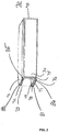
- Fig. 2A depicts a second embodiment of a mattress panel according to the invention.
- the mattress panel 60 has a top layer 62, a filler layer (not shown), a backing layer (not shown), and a flange 67.
- the top layer 62, the filler layer, backing layer and flange 67 are joined at an edge of the mattress panel 60 by overcast stitches 65.
- mattress panel 60 is crowned, for example, center portion 62a of the top layer 62 has a height greater than at the edge 63 and the height of the mattress panel 60 increases from the edge 63 to the center portion 62a at a substantially uniform angle.
- the panel in this embodiment has a picture frame formed around the perimeter of the panel 60 and formed of a foam peripheral edge.
- the foam peripheral picture frame edge may be stitched to the other layers in the panel 60 and optionally stitched to secure the panel 60 to the innercore of the mattress.
- the picture frame peripheral edge may be absent from the panel and a layer of fabric or other material may be placed over the peripheral edge of the gel section and the stitching may pass directly through the gel to secure with the other layers and optionally with the innercore of the mattress.
- a fire resistant layer may also be provided within the panel 60 by incorporating into one or more of the fabric layer, filler layer or backing layer, a fire resistant material, such as halogenated fire resistant fibers, or by forming one of these layers from a material that provides fire resistance or retards flames.
- a separate fire resistant layer may be provided within the panel 60.
- a flange as the terms is used in the mattress construction industry, is a strip of material, generally non-woven, about 4 to 6 inches wide that is sewed to the underside of a mattress panel. Upon assembly of a mattress, the flange on the mattress panel is clipped or otherwise attached to the sides of the spring or foam mattress core to hold the mattress panel in place relative to the mattress core.
- the top layer 62 is formed from five sections of fabric.
- the center section 62a is attached at a first edge to lip section 62b, a second edge to lip section 62c, a third edge to lip section 62d, and a fourth edge to lip section 62e.
- a side of each lip section is joined to the bordering side of another lip section, for example, a side of lip section 62b is joined to the bordering side of lip section 62c, to form top layer 62 with lip sections 62b, 62c, 62d, and 62e.
- the top layer may be formed by cutting wedge shapes from each corner of a sheet of fabric and joining the bordering cut edges together.
- the lip sections 62b, 62c, 62d, and 62e angle downward from center section 62a toward the edges of the top layer 62.
- the lip sections 62b, 62c, 62d, and 62e may influence the expanded shape of the mattress panel 60.
- the edges of mattress panel 60 are compressed together by overcast stitches 65 and expand in height toward the non-quilted center of the mattress panel 60.
- the lip sections 62b, 62c, 62d, and 62e may constrain the filler layer of the mattress panel 60 to expand at the angle of the lip sections 62b, 62c, 62d, and 62e rather than at the free rate of the filler layer material.
- the length of outer edges of sections 62b and 62d are substantially the same as are the length of outer edges of sections 62c and 62e.
- the widths of lip sections 62b, 62c, 62d, and 62e may have uniform widths or varying widths.
- lip section 62b may have a width of about 2 inches
- lip sections 62c and 62e may have width of about 4 inches
- lip section 62d may have a width of about 5 inches.
- Fig. 2B is an exploded cross-sectional view of an edge of an assembled mattress panel of FIG. 2A .
- Overcast stitches 65 join top layer 62, filler layer 68, backing layer 69, and flange 67.
- Edge 63 is compressed together by overcast stitches 65.
- Mattress panel 60 expands in height from edge 63 toward the center section 62a of the mattress panel 60 at the angle of lip section 62d.
- the lip section 62d restrains the filler layer 68 from expanding in a curved fashion as depicted in Fig. 1C .
- the angle formed by the lip section 62d and backing layer 69 may be from about 10 degrees to about 70 degrees, preferably from about 25 degrees to about 45 degrees.
- the center section of the filler layer has a uniform height and decrease at an uniform angle toward its edges.
- the top layer does not substantially restrain the filler layer from expanding.
- Fig. 3 depicts a cross-sectional view of an innerspring mattress embodiment according to one embodiment of the invention.
- the mattress 70 shows an innerspring mattress core 90 with crowned top, bottom and side mattress panels, however, a mattress may be formed with one or more conventional mattress panels.
- the top mattress panel is formed from top layer 71, filler layer 72, and backing layer 73.
- the bottom mattress panel is formed from top layer 77, filler layer 78, and backing layer 79.
- the right side mattress panel is formed from top layer 74, filler layer 75, and backing layer 76.
- the left side mattress panel is formed from top layer 80, filler layer 81, and backing layer 82. Either some or all of the panels may include an optional layer of fire resistant material.
- the mattress core 90 may be covered by a fire resistant enclosure, and the panels placed around the enclosed core.
- the edge 85 joins the top mattress panel to the right side mattress panel.
- the edge 86 joins the right side mattress panel to the bottom mattress panel.
- the edge 87 joins the bottom mattress panel to the left side mattress panel.
- Joining of the top panel to the side border panel or panels may be accomplished by use of a tape edge machine or other suitable system or method.
- the edge 88 joins the top mattress panel to the left side mattress panel. Front and back side panels are not shown. Edges 85, 86, 87, and 88 may be covered with a strip of fabric for aesthetic effect.
- the mattress 70 will have a single side border panel that is sized to wrap around the full periphery of the mattress 70. However, multiple side border panels may also be used.
- the top panel and side border panel may be selected from a number available panels, thereby providing for the panels used to the changed easily during manufacture.
- panels with fire resistant layers may be substituted for panels without such layers, and panels with zoned support, or gel material, may also be readily used or replaced during assembly.
- the mattress 70 may use a side panel constructed according to the systems and methods described herein, with a side bore panel constructed using conventional techniques.
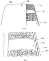
- FIGs. 4 and 5 depict a mattress according to the systems and methods described herein.
- FIG 4 depicts a mattress 90 having a quiltless top panel 92, showing a cut away section that exposes the inner foam layer 94 and a gel section 98 that forms a support zone proximate to where the user's lumbar would be located, and a second zone 100 positioned below the lumbar zone.
- FIG 4 depicts the mattress 90 with a section of the upper fabric layer 92 cut away and replaced with a clear plastic film allowing the internal layers of the panel to be viewed.
- the foam layer 94 includes a zone of gel material 98 that extends from one side of the mattress to the other.
- FIG 5 illustrates that the peripheral edge 102 of the panel was joined by action of a tape edge machine to the side border panel.
- FIG 5 also shows the picture frame edge of the foam panel that is stitched to the other layers (not shown) of the panel 90. The panel 90 is then secured to the innercore of the mattress, also not shown.
- the mattress panels may be attached to the mattress core by hog-rings.
- Hog-ringing is a conventional means of attaching fabric or padding to an innerspring construction, although other mechanical or adhesive means may be used.
- foam, plastic springs, or other resilient material could also be used as a substitute for metal innerspring constructions.
- a mattress panel which provides a substantially smooth exposed surface. Moreover, the mattress panel may have a crowned effect and is understood to provide longer life and be more durable than traditional panels
- the mattress may include a foam core, or a combination of foam and springs.
- the mattress may be one-sided or two-sided.
Landscapes
- Mattresses And Other Support Structures For Chairs And Beds (AREA)
- Laminated Bodies (AREA)
Description
- Mattress manufacture typically employs the covering of a resilient spring interior with a fabric cover that provides much of the comfort and the appearance of the mattress product. Such fabric covers are commonly made of quilted material formed by stitching patterns on multiple layered fabrics formed of a layer of backing material, one or more layers of thick filler material and an outer layer of facing material or ticking. The quilted fabric covers are most often formed on needle sewing machines that stitch the layers of material together with stitched patterns that contribute to the ornamental features of the mattress product. The layers of material become compressed along the lines of thread stitched into the layers. The contrast between the uncompressed layers of material and the indented stitch lines form an uneven surface on the mattress fabric cover.
- The quilting operation by the sewing machines also provides the functional joining of the material that forms the quilted mattress cover. Although the sewing machines are generally reliable, the needles of the sewing machines repeated travel through several layers of material to sew the layers together and may break with use. This may damage, not only the sewing machine, but also the materials being quilted together. Moreover, a sewing machine may malfunction while stitching in various ways, such as mechanically jamming due to fabric or thread accidentally catching a moving part.
-
US 1,205,135 discloses a mattress, comprising a mattress core having an upper primary surface, a mattress panel lying on the upper primary surface of the mattress and having a substantially smooth top surface, the panel having a fabric layer, a filler layer and a backing layer wherein the fabric layer, filler layer, and backing layer are joined at a respective edge Another example of a known mattress is disclosed inUS 6994043 B1 . - There is a need in the art for smooth mattress panels and mattress covers formed without being quilted.
- The present invention provides a mattress according to the characterising portion of claim 1, and a method of manufacturing a mattress panel according to the characterising portion of
claim 10. - The systems and methods described herein include improved mattresses and improved fabric covers for providing mattresses that have smooth surfaces. Additionally, the invention encompasses methods for manufacturing non-quilted mattress covers and for manufacturing mattresses employing non-quilted mattress covers. The systems and methods described herein include mattress panels that can be manufactured separate from the inner core construction, and laid over the inner core to be fastened in place as a sleeping surface for the mattress. Optionally, these mattress panels can include a layer of fire retardant material, that may be added as a layer of material or that may be incorporated into one or more of the layers, such as a filler layer, in the mattress panel.
- The foregoing and other objects, features, and advantages of the invention will become more apparent from the following description and from the claims.
- Various illustrative systems, methods, devices, features and advantages of the invention are described below with reference to the appended drawings, which may not be drawn to scale and in which like parts are designated by like reference designations.
-
FIG. 1A depicts the layers of a mattress panel embodiment of a mattress according to the invention. -
FIG. 1B is a perspective view of an assembled mattress panel embodiment according to the invention. -
FIG. 1C is an exploded cross-sectional view of an edge of an assembled mattress panel embodiment according to the invention. -
FIG. 2A depicts a perspective view of another assembled mattress panel embodiment according to the invention. -
FIG. 2B is an exploded cross-sectional view of an edge of an assembled mattress panel ofFIG. 2A . -
FIG. 3 depicts a cross-sectional view of an embodiment of an innerspring mattress according to the invention. -
FIG 4 presents a cut away view of one mattress according to the invention; and -
FIG. 5 shows in more detail one section of the panel, with a portion cutaway to show internal components. - To provide an overall understanding of the invention, certain illustrative practices and embodiments will now be described, including a mattress having an improved fabric cover with an optional smooth sleeping surface, and methods for manufacturing non-quilted mattress covers and for manufacturing mattresses employing non-quilted mattress covers. Referring now to the figures, in which like numerals designate like elements throughout the several views,
FIGS. 1-5 illustrate various embodiments of the invention. -
Fig. 1A shows several layers of material prior to assembly into a mattress panel. Thefabric layer 10 is the top layer and may be any desired sheet of material, such as cotton, linen, synthetic fibers or a mixture thereof. Thetop layer 10 may be a flat sheet of fabric or may be a substantially flat sheet with an angled lip of fabric (not shown) formed at each edge of thetop layer 10. A lip may be formed by cutting out a wedge of fabric from each corner of thetop layer 10 which border the edge and joining the cut sections of thetop layer 10 together. The lip may be from about 0.5 inches to about 7 inches in length. When a mattress is assembled, thetop layer 10 is an outer surface of the mattress. - The filler layer 20 is the cushioning layer and is formed from foam, latex, visco elastic foam. The filler layer 20 may be from about 0.25 inches to about 5 inches in height, preferably from about 1 inch to about 4 inches. In one preferred embodiment, the filler layer may be a foam substantially 3 inches in height with an ILD of 12 and a density of 1.2. However, in other embodiments, the ILD may be different from this preferred embodiment and the density and ILD can vary according to the application. In certain embodiments the density can range from about 1.0 to about 5.0 and the ILD can vary from, for example, about 10 to about 40 ILD. Other values may also be used without departing from the scope of the invention. The filler layer 20 may have a substantially flat, smooth upper surface or may have a textured or patterned upper surface. According to the invention the center section of the filler layer has a uniform height and decrease at a uniform angle toward its edges. The filler layer 20 may have multiple zones, including a lumbar zone and a shoulder zone. For example, in one embodiment, the panel has a foam filler layer 20 that includes a layer of gel material that is formed within the foam layer and that extends from one side of the mattress to the other side, providing a zone of gel material at an area where the lumbar of a sleeping user would be positioned. The number of zones and the location of the zones may vary according to the application.
- A fire
resistant layer 24 may be placed between the filler layer 20 and thefabric layer 10. In the depicted embodiment, the fireresistant layer 24 includes abarrier fabric 24 which can be incorporated in the panel structure between thefabric layer 10 and the filler layer 20, as shown. However, in the other embodiments, the fire resistant layer may be a sock-like enclosure that fits over and around the filler layer to protect all sides of the filler layer 20 from heat, fire and flame. - Optionally, the
fire barrier fabric 24 can also be attached to one of the layers, for example, thetop layer 10, with an adhesive. Thefire barrier fabric 24, when used as the backing material, can significantly reduce the fire hazard due to the material properties of thefire barrier fabric 24 that will hinder the propagation of a fire to the mattress body. For added fire protection, thefire barrier fabric 24 can also be placed directly under a border ticking. - The exemplary mattress panel depicted in
FIG. 1 includes a fire blocking layer of for example, Fireguard® LWB, sold by Chiquola Industrial Products, LLC, Honea Path, SC, USA, which may optionally be included in both the mattress panels and the borders. The flame resistant material in another embodiment may be KEVLAR™ and PET (polyester) binder fiber, although other suitable materials may be employed and the actual material employed will depend upon the particulars of the application, including mattress type (e.g. open coil, pocketed coil, foam, water, and/or air), mattress size, material costs and other such factors. - In one exemplary optional embodiment, the depicted fire
resistant layer 24 is formed of KEVLARTM fibers and PET fibers that are formed into a layer of fabric. In one practice the layer of fabric is formed by blending and joining the fibers by use of an adhesive or binder. In other embodiments, thelayer 24 may be a layer of fabric formed by a weave of KEVLAR™ and PET fibers. Still other techniques may be used to form thelayer 24 and any suitable technique for forming thelayer 24 may be employed. - The
layer 24 shown inFigure 1A may comprise KEVLAR fibers, but in other embodiments other suitable materials may be employed. Such other materials may be other flame resistant, or sometimes referred to as flame or fire retardant materials, and may include any of the commercially available flame resistant materials. These materials may be categorized into four general groups including inorganic materials, organophosphorous materials, halogenated organic materials (typically halogenated with chlorine or more popularly bromine) and nitrogen based compounds. Commercially available materials are sold under the tradenames NOMEX, KEVLAR, INDURA and others. Other materials include fire resistant balanced corespun yarn such as described inU.S. Patent 5,540,980 . The materials may comprise layers, or fibers incorporated into a layer, with the fibers being chopped fiber, staple fiber, spun yarn, and/or continuous filament. The type of fiber or layer used will depend upon the application. In other embodiments, the flame resistant layer may be a layer of treated material, such as cotton or polyurethane, where the treatment provides a degree of flame resistance. Fire resistant or retardant papers may also be employed. Still other flame resistant materials may be employed without departing from the scope of the invention. - The
backing layer 30 may be formed from any desired sheet of material, such as natural fibers such as cotton or linen, aluminum, fiberglass, synthetic fibers or a mixture thereof. In one preferred embodiment, thebacking layer 30 may be a non-woven polypropylene material weighing from about 0.3 to about 3.0 oz per square yard. Resistance to tearing and flexibility are primary concerns for thebacking layer 30. In another preferred embodiment, the backing layer is formed from a fire-retardant material. - Additional padding, insulating, water-resistant, or fire-resistant layers may be incorporated. The various layers may be may be laminated together, joined by adhesive or otherwise combined to form a single sheet of material. The size of the sheets formed may vary according to the application, but in certain embodiments, the sheets may be sized as is conventional for mattress manufacture, which typically is about 88 inches in width.
-
Fig. 1B depicts an assembledmattress panel 40 wherein the edges 40A of themattress panel 40 are sewn withovercast stitches 50. The edges 40a of themattress panel 40 are compressed by theovercast stitches 50 and have height of about 6 mm to 25 mm (0.25 inches to about 1.0 inches). The center 40b of themattress panel 40 is not compressed by any quilting or stitching and has a height of 25 mm to 102 mm (1,0 inches to about 4 inches), preferably about 76 mm (3 inches). -
Fig. 1C depicts an exploded cross-sectional view of an edge of the assembledmattress panel 40 ofFig. 1B . Overcast stitches 50 jointop layer 10, filler layer 20 andbacking layer 30. Edge 40a is compressed together byovercast stitches 50.Mattress panel 40 expands in height towards the center section of themattress panel 40 as the center section ofmattress panel 40 is not bound by any stitching. - It will be appreciated that
Figs. 1A , I B and 1C depict together another aspect of the invention, which includes a method of manufacturing a mattress having a quiltless crown panel. As depicted above the panels may be formed as shown inFig. 1A from a plurality of layers of materials that are disposed into a flange 7 and that are optionally overcast stitched to be joined together at the edge or edges. Overcast stitching is one preferred method of joining the layers, but in other embodiments and practices, the layers may be joined by other stitching processes, by application of adhesive, by clamping or by combinations thereof. Additionally, in other practices and embodiments the peripheral edges of the layers may be joined together and optionally other portions or sections of the layers may also be joined. This can include the center of the panel, or a border section of the panel, thereby forming a quilt-like appearance along the edge of the panel. Once the layers are joined, the flange 7 is typically secured to the innercore of the mattress to secure the panel in place. The flange 7 may be sized so that the fabric sidewall 21 extends above the interior layers when seated within the flange. In one embodiment for example, and only for example, thelayers - The panel thus formed may be disposed over a mattress core or body and secured thereto. Multiple panels are applied to the mattress core, to cover the top surface, side surfaces and bottom. The mattress panels may be attached to the mattress core by hog-rings, adhesive, plastic rings, stitching and combinations thereof. Other systems for attaching the panels to the mattress may be employed without departing from the scope of this invention. It will be appreciated by those of skill in the art that the manufacturing techniques described herein produce less waste and material take up than current manufacturing quilting methods. Further, quiltless manufacturing may produce consistent panel sizing and higher quality panels, may be more manufacturing friendly and may requires less capital investments to manufacture.
-
Fig. 2A depicts a second embodiment of a mattress panel according to the invention. The mattress panel 60 has atop layer 62, a filler layer (not shown), a backing layer (not shown), and aflange 67. Thetop layer 62, the filler layer, backing layer andflange 67 are joined at an edge of the mattress panel 60 by overcast stitches 65. As more clearly depicted inFig. 2B , mattress panel 60 is crowned, for example,center portion 62a of thetop layer 62 has a height greater than at theedge 63 and the height of the mattress panel 60 increases from theedge 63 to thecenter portion 62a at a substantially uniform angle. The panel in this embodiment has a picture frame formed around the perimeter of the panel 60 and formed of a foam peripheral edge. The foam peripheral picture frame edge may be stitched to the other layers in the panel 60 and optionally stitched to secure the panel 60 to the innercore of the mattress. In other embodiments, the picture frame peripheral edge may be absent from the panel and a layer of fabric or other material may be placed over the peripheral edge of the gel section and the stitching may pass directly through the gel to secure with the other layers and optionally with the innercore of the mattress. - In this alternative embodiment, a fire resistant layer may also be provided within the panel 60 by incorporating into one or more of the fabric layer, filler layer or backing layer, a fire resistant material, such as halogenated fire resistant fibers, or by forming one of these layers from a material that provides fire resistance or retards flames. Optionally, a separate fire resistant layer may be provided within the panel 60.
- A flange, as the terms is used in the mattress construction industry, is a strip of material, generally non-woven, about 4 to 6 inches wide that is sewed to the underside of a mattress panel. Upon assembly of a mattress, the flange on the mattress panel is clipped or otherwise attached to the sides of the spring or foam mattress core to hold the mattress panel in place relative to the mattress core.
- The
top layer 62 is formed from five sections of fabric. Thecenter section 62a is attached at a first edge to lip section 62b, a second edge to lip section 62c, a third edge tolip section 62d, and a fourth edge tolip section 62e. A side of each lip section is joined to the bordering side of another lip section, for example, a side of lip section 62b is joined to the bordering side of lip section 62c, to formtop layer 62 withlip sections - In another embodiment, the top layer may be formed by cutting wedge shapes from each corner of a sheet of fabric and joining the bordering cut edges together.
- The
lip sections center section 62a toward the edges of thetop layer 62. Thelip sections Fig. 1C , the edges of mattress panel 60 are compressed together by overcast stitches 65 and expand in height toward the non-quilted center of the mattress panel 60. Thelip sections lip sections - The length of outer edges of
sections 62b and 62d are substantially the same as are the length of outer edges ofsections 62c and 62e. The widths oflip sections lip sections 62c and 62e may have width of about 4 inches andlip section 62d may have a width of about 5 inches. -
Fig. 2B is an exploded cross-sectional view of an edge of an assembled mattress panel ofFIG. 2A . Overcast stitches 65 jointop layer 62, filler layer 68,backing layer 69, andflange 67.Edge 63 is compressed together by overcast stitches 65. Mattress panel 60 expands in height fromedge 63 toward thecenter section 62a of the mattress panel 60 at the angle oflip section 62d. Thelip section 62d restrains the filler layer 68 from expanding in a curved fashion as depicted inFig. 1C . The angle formed by thelip section 62d andbacking layer 69 may be from about 10 degrees to about 70 degrees, preferably from about 25 degrees to about 45 degrees. - According to the present invention, the center section of the filler layer has a uniform height and decrease at an uniform angle toward its edges. In such embodiments, the top layer does not substantially restrain the filler layer from expanding.
-
Fig. 3 depicts a cross-sectional view of an innerspring mattress embodiment according to one embodiment of the invention. Themattress 70 shows aninnerspring mattress core 90 with crowned top, bottom and side mattress panels, however, a mattress may be formed with one or more conventional mattress panels. The top mattress panel is formed fromtop layer 71,filler layer 72, andbacking layer 73. The bottom mattress panel is formed from top layer 77, filler layer 78, andbacking layer 79. Similarly, the right side mattress panel is formed fromtop layer 74,filler layer 75, andbacking layer 76. The left side mattress panel is formed from top layer 80, filler layer 81, and backing layer 82. Either some or all of the panels may include an optional layer of fire resistant material. Alternatively, themattress core 90 may be covered by a fire resistant enclosure, and the panels placed around the enclosed core. - The
edge 85 joins the top mattress panel to the right side mattress panel. Theedge 86 joins the right side mattress panel to the bottom mattress panel. Theedge 87 joins the bottom mattress panel to the left side mattress panel. Joining of the top panel to the side border panel or panels may be accomplished by use of a tape edge machine or other suitable system or method. The edge 88 joins the top mattress panel to the left side mattress panel. Front and back side panels are not shown.Edges mattress 70 will have a single side border panel that is sized to wrap around the full periphery of themattress 70. However, multiple side border panels may also be used. It will be understood that during manufacture of themattress 70, the top panel and side border panel may be selected from a number available panels, thereby providing for the panels used to the changed easily during manufacture. Thus, panels with fire resistant layers may be substituted for panels without such layers, and panels with zoned support, or gel material, may also be readily used or replaced during assembly. Further, themattress 70 may use a side panel constructed according to the systems and methods described herein, with a side bore panel constructed using conventional techniques. -
FIGs. 4 and 5 depict a mattress according to the systems and methods described herein. In particular,FIG 4 depicts amattress 90 having a quiltlesstop panel 92, showing a cut away section that exposes theinner foam layer 94 and agel section 98 that forms a support zone proximate to where the user's lumbar would be located, and asecond zone 100 positioned below the lumbar zone. Specifically,FIG 4 depicts themattress 90 with a section of theupper fabric layer 92 cut away and replaced with a clear plastic film allowing the internal layers of the panel to be viewed. Thefoam layer 94 includes a zone ofgel material 98 that extends from one side of the mattress to the other.FIG 5 illustrates that theperipheral edge 102 of the panel was joined by action of a tape edge machine to the side border panel.FIG 5 also shows the picture frame edge of the foam panel that is stitched to the other layers (not shown) of thepanel 90. Thepanel 90 is then secured to the innercore of the mattress, also not shown. - The mattress panels may be attached to the mattress core by hog-rings. Hog-ringing is a conventional means of attaching fabric or padding to an innerspring construction, although other mechanical or adhesive means may be used.
- It should also be understood that foam, plastic springs, or other resilient material, could also be used as a substitute for metal innerspring constructions.
- Therefore, it may be seen that a mattress panel is provided which provides a substantially smooth exposed surface. Moreover, the mattress panel may have a crowned effect and is understood to provide longer life and be more durable than traditional panels
- While this invention has been described in specific detail with reference to the disclosed embodiments, it will be understood that many variations and modifications may be effected within the scope of the invention as described in the appended claims. For example, the mattress may include a foam core, or a combination of foam and springs. The mattress may be one-sided or two-sided.
Claims (15)
- A mattress (70), comprising:a mattress core (90) having an upper, a lower, and side primary surfaces,a mattress panel (60) lying on each of the upper, the lower, and side primary surfaces of the mattress core (90) and having a substantially smooth top surface, the mattress panel (60) having,a fabric layer (10, 62, 71, 74, 77, 80, 92),a filler layer (20, 68, 72, 75, 78, 81, 95), anda backing layer (30, 69, 73, 76, 79, 82),wherein the fabric layer, filler layer, and backing layer are joined at a respective edge characterized in that:
the mattress panel (60) is non-quilted and increases in thickness from an edge to a center portion of each of the upper, the lower and side primary surfaces, wherein the filler layer (20,68,72,75,78,81,95) is foam and has a uniform height at a center section and a decrease at a uniform angle towards an edge thereof. - The mattress of claim 1, further including a fire resistant layer (24) disposed within the mattress panel and being joined at the respective edge.
- The mattress of claim 1, wherein the thickness of the non-quilted panel (60) at its edge is from 6 mm (0.25 inches) to 25 mm (1.0 inches).
- The mattress of claim 1, wherein the thickness of the non-quilted panel (60) at its center is from 25 mm (1.0 inches) to 102 mm (4 inches).
- The mattress of claim 2, wherein the fire resistant layer (24) includes a material selected from the group consisting of a halogenated material, Kevlar®, a thermoplastic material, inorganic fire retardant materials, organophosphorous materials, fire resistant balanced corespun yarn, a layer of fire retardant treated cotton, a layer of fire retardant treated polyurethane, and fire retardant treated paper.
- The mattress of claim 1, wherein at least one of the layers includes a fire resistant material.
- The mattress of claim 1, wherein the mattress core (90) comprises a core selected from the group of inner springs, pocketed inner springs, foam, visco-elastic foam, latex, and combinations thereof.
- A method of manufacturing a mattress (70) comprising providing a mattress core (90) defining an upper, a lower, and side primary surface;
providing a fabric layer (10, 62, 71, 74, 77, 80, 92),
providing a filler layer (20, 68, 72, 75, 78, 81, 95), and
providing a backing layer (30, 69, 73, 76, 79, 82),
forming a common edge with the fabric, filler and backing layers, and
joining the common edge with the fabric, filler and backing layers form a mattress panel (60),
characterized by:attaching the mattress panel (60) to each one of the upper, the lower and the side primary surfaces,wherein the mattress panel (60) is non-quilted and the upper and the side primary surfaces each has a thickness that increased from an edge to a center portion, and wherein the filler layer (20,68,72,75,78,81,95) is foam and has a uniform height at a center section and a decrease at a uniform angle towards an edge thereof. - The method of claim 8, further comprising providing a fire resistant layer (24) between the fabric layer and the backing layer.
- The method of claim 8, further comprising providing two or more layers having substantially similar length and width.
- The method of claim 8, further comprising clamping two or more layers to positioning the two or more layers for joining.
- The method of claim 8, wherein joining comprises stitching, gluing, stapling, tying, melting or overcast sewing.
- The method of claim 8, further comprising providing a padding layer.
- The method of claim 8, comprising attaching a flange to the mattress panel.
- The method of claim 8, wherein a common edge is formed either: by lining up the edges of the fabric, filler, and backing layers or by overlaying the fabric, filler and backing layers and cutting the fabric, filler, and backing layers simultaneously.
Applications Claiming Priority (2)
| Application Number | Priority Date | Filing Date | Title |
|---|---|---|---|
| US11/416,927 US11259647B2 (en) | 2006-05-02 | 2006-05-02 | Mattress with crowned panel |
| PCT/US2007/010626 WO2007130450A2 (en) | 2006-05-02 | 2007-05-02 | Mattress with crowned panel |
Publications (2)
| Publication Number | Publication Date |
|---|---|
| EP2019610A2 EP2019610A2 (en) | 2009-02-04 |
| EP2019610B1 true EP2019610B1 (en) | 2018-12-26 |
Family
ID=38654669
Family Applications (1)
| Application Number | Title | Priority Date | Filing Date |
|---|---|---|---|
| EP07794490.8A Active EP2019610B1 (en) | 2006-05-02 | 2007-05-02 | Mattress with non-quilted panel |
Country Status (6)
| Country | Link |
|---|---|
| US (2) | US11259647B2 (en) |
| EP (1) | EP2019610B1 (en) |
| JP (1) | JP2009535166A (en) |
| MX (1) | MX2008014083A (en) |
| TW (1) | TWI475972B (en) |
| WO (1) | WO2007130450A2 (en) |
Cited By (1)
| Publication number | Priority date | Publication date | Assignee | Title |
|---|---|---|---|---|
| US11259647B2 (en) | 2006-05-02 | 2022-03-01 | Dreamwell, Ltd. | Mattress with crowned panel |
Families Citing this family (10)
| Publication number | Priority date | Publication date | Assignee | Title |
|---|---|---|---|---|
| EP1778056B1 (en) * | 2004-07-16 | 2013-03-06 | Dreamwell, Ltd. | Mattress with removable top |
| US10130189B2 (en) * | 2007-08-15 | 2018-11-20 | Precision Fabrics Group, Inc. | Laminated textile materials that reduce flame propagation, articles incorporating same, and methods of making same |
| GB2495499B (en) | 2011-10-11 | 2019-02-06 | Hs Products Ltd | Hybrid spring |
| GB2506104B (en) * | 2012-08-10 | 2018-12-12 | Hs Products Ltd | Resilient unit with different major surfaces |
| US9635952B1 (en) | 2014-11-19 | 2017-05-02 | Hickory Springs Manufacturing Company | Sleep fabric layer with individually pocketed coils |
| GB201708635D0 (en) | 2017-05-31 | 2017-07-12 | Hs Products Ltd | Pocketed spring unit and method manufacture |
| GB201708639D0 (en) | 2017-05-31 | 2017-07-12 | Hs Products Ltd | Transportation Apparatus and method |
| US20190059600A1 (en) * | 2017-08-23 | 2019-02-28 | Dreamwell, Ltd. | Mattress foundation and process of manufacture |
| US11559143B2 (en) * | 2019-12-20 | 2023-01-24 | Indratech Llc | Non-sewn mattress and method of manufacturing thereof |
| WO2022001646A1 (en) * | 2020-06-29 | 2022-01-06 | 际诺思股份公司 | Mattress and method for manufacturing same |
Family Cites Families (86)
| Publication number | Priority date | Publication date | Assignee | Title |
|---|---|---|---|---|
| US848437A (en) * | 1906-09-07 | 1907-03-26 | Mae Brown | Mattress. |
| US1205135A (en) * | 1912-03-11 | 1916-11-14 | Ernest L Farrow | Spring-mattress. |
| US1238302A (en) * | 1917-01-31 | 1917-08-28 | George Wuest | Mattress. |
| US1430946A (en) * | 1922-03-20 | 1922-10-03 | Jr David Clagett | Mattress or cushion |
| US1710400A (en) * | 1925-10-05 | 1929-04-23 | Earl R Bebout | Chiropractic table |
| US1925766A (en) * | 1930-12-15 | 1933-09-05 | Karpen & Bros S | Mattress and its manufacture |
| US2265304A (en) * | 1940-02-19 | 1941-12-09 | Jr Fred A Nachman | Jacketed spring assembly |
| US2316687A (en) * | 1941-01-07 | 1943-04-13 | Perley D Hammond | Molded cushion |
| US2403043A (en) * | 1943-05-10 | 1946-07-02 | Sealy | Mattress |
| US2528313A (en) * | 1949-01-21 | 1950-10-31 | William L Kessler | Mattress covering sheet |
| US2675566A (en) * | 1950-03-03 | 1954-04-20 | Leonard Chicago Corp | Bedspring construction |
| US2619659A (en) * | 1950-09-26 | 1952-12-02 | Us Rubber Co | Reversible sponge cushion |
| US2621341A (en) * | 1951-01-04 | 1952-12-16 | Clarence F Woods | Two-section mattress |
| DE1036036B (en) | 1955-12-16 | 1958-08-07 | Heinrich Haeussling Fa | Shaped body for upholstering seating, mattresses, etc. Like., In particular of motor vehicle seats, and method for its production |
| US2926660A (en) * | 1956-04-11 | 1960-03-01 | Thompson Joseph Clay | Chiropractic table |
| US2858881A (en) * | 1956-04-26 | 1958-11-04 | Armour & Co | Fabricated polyurethane cushion |
| US2856615A (en) * | 1957-07-05 | 1958-10-21 | Cirocco Rosina | Mattress cover |
| US2987735A (en) * | 1957-07-26 | 1961-06-13 | Walter P Nail | Control of inflatable articles |
| US3308491A (en) * | 1965-12-22 | 1967-03-14 | Stryker Corp | Cushion structure |
| US3370306A (en) * | 1966-02-03 | 1968-02-27 | Henry H. Lovette | Body supporting units of sleeping or reclining furniture or equipment |
| US3751742A (en) * | 1971-06-21 | 1973-08-14 | R Worley | Filler for use between a bedspring and a separate mattress |
| US3747916A (en) * | 1971-07-19 | 1973-07-24 | J Benson | Chiropractic table |
| US3857126A (en) * | 1973-07-16 | 1974-12-31 | Morton Norwich Products Inc | Ignition resistant mattress construction |
| FR2401639A1 (en) * | 1977-09-06 | 1979-03-30 | Leroy Michel | REST FURNITURE ESPECIALLY FOR VENTRAL DECUBITUS |
| US4187567A (en) * | 1978-08-04 | 1980-02-12 | Crowther Curt P | Waterbed |
| US4244065A (en) * | 1979-05-21 | 1981-01-13 | David Hartwell | Water bed construction |
| US4281425A (en) * | 1979-08-06 | 1981-08-04 | Jacobs Annella E | Neonatal flotation pad |
| US4330893A (en) * | 1979-10-22 | 1982-05-25 | Ichinosuke Matsui | Water bed |
| US4388738A (en) * | 1981-02-23 | 1983-06-21 | Sealy, Incorporated | Mattress construction and mattress cover therein |
| US4504991A (en) | 1982-06-07 | 1985-03-19 | Sealy, Incorporated | Fire-resistant mattress and high strength fire-retardant composite |
| DE3377891D1 (en) * | 1982-11-19 | 1988-10-13 | Courtaulds Plc | Mattress for supporting the human body |
| CA1231471A (en) * | 1984-06-21 | 1988-01-12 | Ned W. Mizelle | Mattress and supporting structure therefor |
| DE8509301U1 (en) * | 1985-03-27 | 1985-05-09 | Wohnform GmbH & Co Werkstätten KG, 6101 Groß-Bieberau | Waterbed |
| US4720415A (en) * | 1985-07-30 | 1988-01-19 | Kimberly-Clark Corporation | Composite elastomeric material and process for making the same |
| DE3608342A1 (en) * | 1986-01-10 | 1987-07-16 | Werner Lueck | Cushion body made of soft foam |
| US4829615A (en) * | 1987-08-28 | 1989-05-16 | Raymond Edward A | Tapered mattress |
| EP0360733B1 (en) * | 1988-08-25 | 1994-01-26 | Oba Ag | Anti-pressure sores mattress |
| USD313722S (en) * | 1988-11-08 | 1991-01-15 | Axelson Norman A | Water mat |
| US5144705A (en) * | 1989-03-15 | 1992-09-08 | Rogers John E | Seat cushions including a plurality of individual support cells |
| US4962546A (en) * | 1989-07-20 | 1990-10-16 | Perfect Fit Industries, Inc. | Mattress pad with stretch-wall construction |
| US5475881A (en) * | 1989-08-23 | 1995-12-19 | L&P Property Management Company | Sleep enhancing posturized mattress and mattress cover |
| US5003655A (en) * | 1990-02-16 | 1991-04-02 | Kafai Malakeh B | Bed sheet assembly |
| US5285541A (en) * | 1992-03-12 | 1994-02-15 | Simmons Company | Flotation system including improved cushioning and support features |
| US5201780A (en) * | 1991-09-06 | 1993-04-13 | Jay Medical, Ltd. | Anti-decubitus mattress pad |
| US5327597A (en) * | 1992-07-02 | 1994-07-12 | Michael Rothbard | Convoluted mattress pad having multiple proximate peaks |
| US5523144A (en) | 1992-10-07 | 1996-06-04 | Valwhat Enterprises, Inc. | Bedding structure with quilted-in lumbar support |
| USD347541S (en) * | 1992-10-20 | 1994-06-07 | Cook Joseph R | Lazarette cushion |
| US5353455A (en) * | 1993-05-12 | 1994-10-11 | Carpenter Co. | Padding body with individual modular elements |
| US5406660A (en) * | 1994-03-07 | 1995-04-18 | Strata Flotation, Inc. | Waterbed mattress with plastic netting fill |
| US6491717B1 (en) * | 1994-10-28 | 2002-12-10 | Eric D. Stanley | Pulsating liquid saturated foam container |
| US5845350A (en) * | 1996-02-16 | 1998-12-08 | Infant Advantage, Inc. | Cradle mattress |
| US5809593A (en) * | 1997-04-11 | 1998-09-22 | Hollander Home Fashions Corp. | Mattress cover with wide elastic strip |
| US6163907A (en) * | 1998-04-03 | 2000-12-26 | Larson; Lynn D. | Removable mattress top assembly |
| US6098224A (en) * | 1998-10-02 | 2000-08-08 | Simmons Company | Pillow top mattress assemblies |
| US6351864B1 (en) * | 1999-06-28 | 2002-03-05 | David M. Karafa | Institutional bedding with integral pillow and mattress |
| JP4601887B2 (en) * | 1999-12-29 | 2010-12-22 | ヒル−ロム サービシーズ,インコーポレイティド | Hospital bed |
| AU146054S (en) * | 2000-01-26 | 2001-11-30 | Huntleigh Technology Ltd | A two part mattress |
| US6823548B2 (en) * | 2002-10-01 | 2004-11-30 | Spungold, Inc. | Composite fire barrier and thermal insulation fabric for mattresses and mattress foundations |
| US6721982B2 (en) * | 2002-03-25 | 2004-04-20 | Sealy Technology Llc | Quilt-stitched internal mattress pillows |
| US6772825B2 (en) * | 2002-11-04 | 2004-08-10 | Charles A. Lachenbruch | Heat exchange support surface |
| US6842927B2 (en) * | 2003-03-04 | 2005-01-18 | England, Inc. | Mattress |
| US6994043B1 (en) * | 2003-05-20 | 2006-02-07 | Atlanta Attachment Company | Method of forming a mattress |
| US6968585B2 (en) * | 2003-09-22 | 2005-11-29 | Mark Shaw | Antidecubitus heel pad |
| US7254852B2 (en) * | 2003-11-14 | 2007-08-14 | Carpenter, Co. | Cushioning device |
| CA2596098C (en) * | 2004-02-18 | 2009-01-27 | Save Our Sleep, Inc. | Multi-layer mattress protector |
| US7240386B1 (en) * | 2004-05-20 | 2007-07-10 | King Koil Licensing Company, Inc. | Multi-layer mattress with an air filtration foundation |
| US8997279B1 (en) * | 2004-05-20 | 2015-04-07 | King Koil Licensing Company, Inc. | Multi-layer mattress with an air filtration foundation |
| DE602005001973T2 (en) * | 2004-06-04 | 2008-02-21 | Hill-Rom Services, Inc., Wilmington | Mattress with heel pressure relief part |
| CA2509756A1 (en) * | 2004-06-12 | 2005-12-12 | L & P Property Management Company | High air flow foam bedding products |
| USD554208S1 (en) * | 2005-04-28 | 2007-10-30 | Karen Palaszek | Yoga mat |
| US7603729B2 (en) * | 2005-10-07 | 2009-10-20 | Conmedisys, Inc. | Patient lift and transfer device |
| US7296314B2 (en) * | 2006-01-04 | 2007-11-20 | Encompass Group, Llc | Patient support surface |
| US20080028528A1 (en) * | 2006-01-27 | 2008-02-07 | Wilson Travis L | Custom orthotic neck curve builder system |
| US11259647B2 (en) | 2006-05-02 | 2022-03-01 | Dreamwell, Ltd. | Mattress with crowned panel |
| US8607387B2 (en) * | 2006-11-20 | 2013-12-17 | Stryker Corporation | Multi-walled gelastic mattress system |
| US7467432B2 (en) * | 2007-04-13 | 2008-12-23 | Pacific Coast Feather Company | Pillow with central spaced internal baffles |
| US7996937B2 (en) * | 2008-12-18 | 2011-08-16 | Direct Supply, Inc. | Mattress and sheet combination providing wrinkle free surface with raised perimeters |
| US9167919B2 (en) * | 2009-03-03 | 2015-10-27 | Smartsilk Corporation Inc. | Cover for a mattress |
| GB2492727A (en) * | 2010-04-16 | 2013-01-09 | Rmc Solutions Inc | Systems and methods for body support |
| US8832888B2 (en) * | 2011-07-29 | 2014-09-16 | Dreamwell, Ltd. | Mattress and side rail assemblies having high airflow |
| WO2014018061A1 (en) * | 2012-07-27 | 2014-01-30 | Tempur-Pedic Management, Inc. | Adjustable mattress foundation |
| US9131781B2 (en) * | 2012-12-27 | 2015-09-15 | Select Comfort Corporation | Distribution pad for a temperature control system |
| US20160198862A1 (en) * | 2013-01-26 | 2016-07-14 | David L. Farley | Mattress |
| ITVR20130084A1 (en) * | 2013-04-08 | 2014-10-09 | Technogel Italia Srl | PADDING ELEMENT FOR SEATING AND METHOD FOR ITS REALIZATION |
| US9861208B2 (en) * | 2013-06-07 | 2018-01-09 | Mattress Development Company Of Delaware, Llc | Multifunctional mattress systems |
| US9854922B1 (en) * | 2017-01-18 | 2018-01-02 | Pranasleep, LLC | Ergonomic mattress having support sections with internal variations |
-
2006
- 2006-05-02 US US11/416,927 patent/US11259647B2/en active Active
-
2007
- 2007-04-27 TW TW096114982A patent/TWI475972B/en active
- 2007-05-02 MX MX2008014083A patent/MX2008014083A/en not_active Application Discontinuation
- 2007-05-02 JP JP2009509684A patent/JP2009535166A/en not_active Abandoned
- 2007-05-02 EP EP07794490.8A patent/EP2019610B1/en active Active
- 2007-05-02 WO PCT/US2007/010626 patent/WO2007130450A2/en active Application Filing
-
2022
- 2022-02-14 US US17/670,557 patent/US11452383B2/en active Active
Non-Patent Citations (1)
| Title |
|---|
| None * |
Cited By (2)
| Publication number | Priority date | Publication date | Assignee | Title |
|---|---|---|---|---|
| US11259647B2 (en) | 2006-05-02 | 2022-03-01 | Dreamwell, Ltd. | Mattress with crowned panel |
| US11452383B2 (en) | 2006-05-02 | 2022-09-27 | Dreamwell, Ltd. | Mattress with crowned panel |
Also Published As
| Publication number | Publication date |
|---|---|
| US20070256246A1 (en) | 2007-11-08 |
| WO2007130450A3 (en) | 2008-01-24 |
| EP2019610A2 (en) | 2009-02-04 |
| WO2007130450A2 (en) | 2007-11-15 |
| TWI475972B (en) | 2015-03-11 |
| JP2009535166A (en) | 2009-10-01 |
| US20220248868A1 (en) | 2022-08-11 |
| US11259647B2 (en) | 2022-03-01 |
| US11452383B2 (en) | 2022-09-27 |
| MX2008014083A (en) | 2009-01-20 |
| TW200806226A (en) | 2008-02-01 |
Similar Documents
| Publication | Publication Date | Title |
|---|---|---|
| US11452383B2 (en) | Mattress with crowned panel | |
| US6499157B1 (en) | Mattress coverings and methods of making | |
| US6353947B1 (en) | Mattress coverings | |
| US5996148A (en) | Mattress coverings with two elastic cords | |
| US5625912A (en) | Mattress coverings | |
| US6721982B2 (en) | Quilt-stitched internal mattress pillows | |
| US7617556B2 (en) | Mattress systems and methods of making | |
| AU2005295793A1 (en) | Mattress with flame resistant moisture barrier | |
| US11627812B2 (en) | Mattress top panel and mattress assemblies with improved airflow | |
| WO2013106066A1 (en) | Low shear mattress topper constructions | |
| US6983706B2 (en) | Method of manufacturing cover for a bedding product | |
| US8601621B2 (en) | Semi-fitted blanket and method of manufacturing same | |
| KR20070093428A (en) | High loft flame resistant batting for mattresses and furniture and processes for making same | |
| WO1990006073A1 (en) | A heat insulating, quilted web material and articles made therefrom | |
| US20040035534A1 (en) | Interior treatments and furniture of fibrous felt construction | |
| JP2005143567A (en) | Multilayer type mattress, spread pad or bed pad, and its manufacturing method | |
| US7013514B1 (en) | Fire retardant mattress | |
| US10779658B1 (en) | Mattress top for innerspring mattress | |
| JP3145558U (en) | Thermal insulation sheet | |
| JPH09154689A (en) | Multilayer coverlet | |
| KR20130002002U (en) | Mattress with reinforced padded side | |
| MXPA06008445A (en) | Multilayer spunlaced nonwoven fire blocking composite | |
| JPH01285287A (en) | Quilting cloth having multilayer structure |
Legal Events
| Date | Code | Title | Description |
|---|---|---|---|
| PUAI | Public reference made under article 153(3) epc to a published international application that has entered the european phase |
Free format text: ORIGINAL CODE: 0009012 |
|
| 17P | Request for examination filed |
Effective date: 20081202 |
|
| AK | Designated contracting states |
Kind code of ref document: A2 Designated state(s): AT BE BG CH CY CZ DE DK EE ES FI FR GB GR HU IE IS IT LI LT LU LV MC MT NL PL PT RO SE SI SK TR |
|
| AX | Request for extension of the european patent |
Extension state: AL BA HR MK RS |
|
| 17Q | First examination report despatched |
Effective date: 20090414 |
|
| REG | Reference to a national code |
Ref country code: HK Ref legal event code: DE Ref document number: 1127264 Country of ref document: HK |
|
| GRAP | Despatch of communication of intention to grant a patent |
Free format text: ORIGINAL CODE: EPIDOSNIGR1 |
|
| STAA | Information on the status of an ep patent application or granted ep patent |
Free format text: STATUS: GRANT OF PATENT IS INTENDED |
|
| RIC1 | Information provided on ipc code assigned before grant |
Ipc: A47C 27/00 20060101AFI20180622BHEP Ipc: A47C 31/00 20060101ALI20180622BHEP |
|
| INTG | Intention to grant announced |
Effective date: 20180711 |
|
| GRAS | Grant fee paid |
Free format text: ORIGINAL CODE: EPIDOSNIGR3 |
|
| GRAA | (expected) grant |
Free format text: ORIGINAL CODE: 0009210 |
|
| STAA | Information on the status of an ep patent application or granted ep patent |
Free format text: STATUS: THE PATENT HAS BEEN GRANTED |
|
| AK | Designated contracting states |
Kind code of ref document: B1 Designated state(s): AT BE BG CH CY CZ DE DK EE ES FI FR GB GR HU IE IS IT LI LT LU LV MC MT NL PL PT RO SE SI SK TR |
|
| AX | Request for extension of the european patent |
Extension state: AL BA HR MK RS |
|
| REG | Reference to a national code |
Ref country code: GB Ref legal event code: FG4D |
|
| REG | Reference to a national code |
Ref country code: CH Ref legal event code: EP |
|
| REG | Reference to a national code |
Ref country code: AT Ref legal event code: REF Ref document number: 1080236 Country of ref document: AT Kind code of ref document: T Effective date: 20190115 |
|
| REG | Reference to a national code |
Ref country code: IE Ref legal event code: FG4D |
|
| REG | Reference to a national code |
Ref country code: DE Ref legal event code: R096 Ref document number: 602007057246 Country of ref document: DE |
|
| PG25 | Lapsed in a contracting state [announced via postgrant information from national office to epo] |
Ref country code: BG Free format text: LAPSE BECAUSE OF FAILURE TO SUBMIT A TRANSLATION OF THE DESCRIPTION OR TO PAY THE FEE WITHIN THE PRESCRIBED TIME-LIMIT Effective date: 20190326 Ref country code: LT Free format text: LAPSE BECAUSE OF FAILURE TO SUBMIT A TRANSLATION OF THE DESCRIPTION OR TO PAY THE FEE WITHIN THE PRESCRIBED TIME-LIMIT Effective date: 20181226 Ref country code: FI Free format text: LAPSE BECAUSE OF FAILURE TO SUBMIT A TRANSLATION OF THE DESCRIPTION OR TO PAY THE FEE WITHIN THE PRESCRIBED TIME-LIMIT Effective date: 20181226 Ref country code: LV Free format text: LAPSE BECAUSE OF FAILURE TO SUBMIT A TRANSLATION OF THE DESCRIPTION OR TO PAY THE FEE WITHIN THE PRESCRIBED TIME-LIMIT Effective date: 20181226 |
|
| REG | Reference to a national code |
Ref country code: NL Ref legal event code: MP Effective date: 20181226 |
|
| REG | Reference to a national code |
Ref country code: LT Ref legal event code: MG4D |
|
| PG25 | Lapsed in a contracting state [announced via postgrant information from national office to epo] |
Ref country code: SE Free format text: LAPSE BECAUSE OF FAILURE TO SUBMIT A TRANSLATION OF THE DESCRIPTION OR TO PAY THE FEE WITHIN THE PRESCRIBED TIME-LIMIT Effective date: 20181226 Ref country code: GR Free format text: LAPSE BECAUSE OF FAILURE TO SUBMIT A TRANSLATION OF THE DESCRIPTION OR TO PAY THE FEE WITHIN THE PRESCRIBED TIME-LIMIT Effective date: 20190327 |
|
| REG | Reference to a national code |
Ref country code: AT Ref legal event code: MK05 Ref document number: 1080236 Country of ref document: AT Kind code of ref document: T Effective date: 20181226 |
|
| PG25 | Lapsed in a contracting state [announced via postgrant information from national office to epo] |
Ref country code: NL Free format text: LAPSE BECAUSE OF FAILURE TO SUBMIT A TRANSLATION OF THE DESCRIPTION OR TO PAY THE FEE WITHIN THE PRESCRIBED TIME-LIMIT Effective date: 20181226 |
|
| PG25 | Lapsed in a contracting state [announced via postgrant information from national office to epo] |
Ref country code: ES Free format text: LAPSE BECAUSE OF FAILURE TO SUBMIT A TRANSLATION OF THE DESCRIPTION OR TO PAY THE FEE WITHIN THE PRESCRIBED TIME-LIMIT Effective date: 20181226 Ref country code: PL Free format text: LAPSE BECAUSE OF FAILURE TO SUBMIT A TRANSLATION OF THE DESCRIPTION OR TO PAY THE FEE WITHIN THE PRESCRIBED TIME-LIMIT Effective date: 20181226 Ref country code: IT Free format text: LAPSE BECAUSE OF FAILURE TO SUBMIT A TRANSLATION OF THE DESCRIPTION OR TO PAY THE FEE WITHIN THE PRESCRIBED TIME-LIMIT Effective date: 20181226 Ref country code: CZ Free format text: LAPSE BECAUSE OF FAILURE TO SUBMIT A TRANSLATION OF THE DESCRIPTION OR TO PAY THE FEE WITHIN THE PRESCRIBED TIME-LIMIT Effective date: 20181226 Ref country code: PT Free format text: LAPSE BECAUSE OF FAILURE TO SUBMIT A TRANSLATION OF THE DESCRIPTION OR TO PAY THE FEE WITHIN THE PRESCRIBED TIME-LIMIT Effective date: 20190426 |
|
| PG25 | Lapsed in a contracting state [announced via postgrant information from national office to epo] |
Ref country code: EE Free format text: LAPSE BECAUSE OF FAILURE TO SUBMIT A TRANSLATION OF THE DESCRIPTION OR TO PAY THE FEE WITHIN THE PRESCRIBED TIME-LIMIT Effective date: 20181226 Ref country code: RO Free format text: LAPSE BECAUSE OF FAILURE TO SUBMIT A TRANSLATION OF THE DESCRIPTION OR TO PAY THE FEE WITHIN THE PRESCRIBED TIME-LIMIT Effective date: 20181226 Ref country code: IS Free format text: LAPSE BECAUSE OF FAILURE TO SUBMIT A TRANSLATION OF THE DESCRIPTION OR TO PAY THE FEE WITHIN THE PRESCRIBED TIME-LIMIT Effective date: 20190426 Ref country code: SK Free format text: LAPSE BECAUSE OF FAILURE TO SUBMIT A TRANSLATION OF THE DESCRIPTION OR TO PAY THE FEE WITHIN THE PRESCRIBED TIME-LIMIT Effective date: 20181226 |
|
| REG | Reference to a national code |
Ref country code: DE Ref legal event code: R097 Ref document number: 602007057246 Country of ref document: DE |
|
| PG25 | Lapsed in a contracting state [announced via postgrant information from national office to epo] |
Ref country code: DK Free format text: LAPSE BECAUSE OF FAILURE TO SUBMIT A TRANSLATION OF THE DESCRIPTION OR TO PAY THE FEE WITHIN THE PRESCRIBED TIME-LIMIT Effective date: 20181226 Ref country code: AT Free format text: LAPSE BECAUSE OF FAILURE TO SUBMIT A TRANSLATION OF THE DESCRIPTION OR TO PAY THE FEE WITHIN THE PRESCRIBED TIME-LIMIT Effective date: 20181226 |
|
| PLBE | No opposition filed within time limit |
Free format text: ORIGINAL CODE: 0009261 |
|
| STAA | Information on the status of an ep patent application or granted ep patent |
Free format text: STATUS: NO OPPOSITION FILED WITHIN TIME LIMIT |
|
| 26N | No opposition filed |
Effective date: 20190927 |
|
| REG | Reference to a national code |
Ref country code: CH Ref legal event code: PL |
|
| PG25 | Lapsed in a contracting state [announced via postgrant information from national office to epo] |
Ref country code: LI Free format text: LAPSE BECAUSE OF NON-PAYMENT OF DUE FEES Effective date: 20190531 Ref country code: CH Free format text: LAPSE BECAUSE OF NON-PAYMENT OF DUE FEES Effective date: 20190531 Ref country code: MC Free format text: LAPSE BECAUSE OF FAILURE TO SUBMIT A TRANSLATION OF THE DESCRIPTION OR TO PAY THE FEE WITHIN THE PRESCRIBED TIME-LIMIT Effective date: 20181226 |
|
| REG | Reference to a national code |
Ref country code: BE Ref legal event code: MM Effective date: 20190531 |
|
| PG25 | Lapsed in a contracting state [announced via postgrant information from national office to epo] |
Ref country code: LU Free format text: LAPSE BECAUSE OF NON-PAYMENT OF DUE FEES Effective date: 20190502 Ref country code: SI Free format text: LAPSE BECAUSE OF FAILURE TO SUBMIT A TRANSLATION OF THE DESCRIPTION OR TO PAY THE FEE WITHIN THE PRESCRIBED TIME-LIMIT Effective date: 20181226 |
|
| PG25 | Lapsed in a contracting state [announced via postgrant information from national office to epo] |
Ref country code: TR Free format text: LAPSE BECAUSE OF FAILURE TO SUBMIT A TRANSLATION OF THE DESCRIPTION OR TO PAY THE FEE WITHIN THE PRESCRIBED TIME-LIMIT Effective date: 20181226 |
|
| PG25 | Lapsed in a contracting state [announced via postgrant information from national office to epo] |
Ref country code: IE Free format text: LAPSE BECAUSE OF NON-PAYMENT OF DUE FEES Effective date: 20190502 |
|
| PG25 | Lapsed in a contracting state [announced via postgrant information from national office to epo] |
Ref country code: BE Free format text: LAPSE BECAUSE OF NON-PAYMENT OF DUE FEES Effective date: 20190531 |
|
| PG25 | Lapsed in a contracting state [announced via postgrant information from national office to epo] |
Ref country code: CY Free format text: LAPSE BECAUSE OF FAILURE TO SUBMIT A TRANSLATION OF THE DESCRIPTION OR TO PAY THE FEE WITHIN THE PRESCRIBED TIME-LIMIT Effective date: 20181226 |
|
| PG25 | Lapsed in a contracting state [announced via postgrant information from national office to epo] |
Ref country code: HU Free format text: LAPSE BECAUSE OF FAILURE TO SUBMIT A TRANSLATION OF THE DESCRIPTION OR TO PAY THE FEE WITHIN THE PRESCRIBED TIME-LIMIT; INVALID AB INITIO Effective date: 20070502 Ref country code: MT Free format text: LAPSE BECAUSE OF FAILURE TO SUBMIT A TRANSLATION OF THE DESCRIPTION OR TO PAY THE FEE WITHIN THE PRESCRIBED TIME-LIMIT Effective date: 20181226 |
|
| P01 | Opt-out of the competence of the unified patent court (upc) registered |
Effective date: 20230703 |
|
| PGFP | Annual fee paid to national office [announced via postgrant information from national office to epo] |
Ref country code: GB Payment date: 20240527 Year of fee payment: 18 |
|
| PGFP | Annual fee paid to national office [announced via postgrant information from national office to epo] |
Ref country code: DE Payment date: 20240530 Year of fee payment: 18 |
|
| PGFP | Annual fee paid to national office [announced via postgrant information from national office to epo] |
Ref country code: FR Payment date: 20240527 Year of fee payment: 18 |