EP2019451A2 - Elément de fonction d'une installation de télécommunication - Google Patents
Elément de fonction d'une installation de télécommunication Download PDFInfo
- Publication number
- EP2019451A2 EP2019451A2 EP08010768A EP08010768A EP2019451A2 EP 2019451 A2 EP2019451 A2 EP 2019451A2 EP 08010768 A EP08010768 A EP 08010768A EP 08010768 A EP08010768 A EP 08010768A EP 2019451 A2 EP2019451 A2 EP 2019451A2
- Authority
- EP
- European Patent Office
- Prior art keywords
- contact springs
- contact
- exhibitions
- functional element
- designed
- Prior art date
- Legal status (The legal status is an assumption and is not a legal conclusion. Google has not performed a legal analysis and makes no representation as to the accuracy of the status listed.)
- Granted
Links
- 238000012360 testing method Methods 0.000 claims abstract description 7
- 230000001681 protective effect Effects 0.000 claims description 16
- 238000003780 insertion Methods 0.000 claims description 3
- 230000037431 insertion Effects 0.000 claims description 3
- 238000000926 separation method Methods 0.000 abstract description 3
- 206010041662 Splinter Diseases 0.000 description 2
- 230000001419 dependent effect Effects 0.000 description 1
- 238000010292 electrical insulation Methods 0.000 description 1
- 230000006870 function Effects 0.000 description 1
- 238000004519 manufacturing process Methods 0.000 description 1
- 230000009993 protective function Effects 0.000 description 1
Images


Classifications
-
- H—ELECTRICITY
- H01—ELECTRIC ELEMENTS
- H01R—ELECTRICALLY-CONDUCTIVE CONNECTIONS; STRUCTURAL ASSOCIATIONS OF A PLURALITY OF MUTUALLY-INSULATED ELECTRICAL CONNECTING ELEMENTS; COUPLING DEVICES; CURRENT COLLECTORS
- H01R9/00—Structural associations of a plurality of mutually-insulated electrical connecting elements, e.g. terminal strips or terminal blocks; Terminals or binding posts mounted upon a base or in a case; Bases therefor
- H01R9/22—Bases, e.g. strip, block, panel
- H01R9/24—Terminal blocks
-
- H—ELECTRICITY
- H04—ELECTRIC COMMUNICATION TECHNIQUE
- H04Q—SELECTING
- H04Q1/00—Details of selecting apparatus or arrangements
- H04Q1/02—Constructional details
- H04Q1/14—Distribution frames
- H04Q1/142—Terminal blocks for distribution frames
-
- H—ELECTRICITY
- H01—ELECTRIC ELEMENTS
- H01R—ELECTRICALLY-CONDUCTIVE CONNECTIONS; STRUCTURAL ASSOCIATIONS OF A PLURALITY OF MUTUALLY-INSULATED ELECTRICAL CONNECTING ELEMENTS; COUPLING DEVICES; CURRENT COLLECTORS
- H01R13/00—Details of coupling devices of the kinds covered by groups H01R12/70 or H01R24/00 - H01R33/00
- H01R13/66—Structural association with built-in electrical component
- H01R13/70—Structural association with built-in electrical component with built-in switch
- H01R13/703—Structural association with built-in electrical component with built-in switch operated by engagement or disengagement of coupling parts, e.g. dual-continuity coupling part
- H01R13/7031—Shorting, shunting or bussing of different terminals interrupted or effected on engagement of coupling part, e.g. for ESD protection, line continuity
- H01R13/7033—Shorting, shunting or bussing of different terminals interrupted or effected on engagement of coupling part, e.g. for ESD protection, line continuity making use of elastic extensions of the terminals
-
- H—ELECTRICITY
- H01—ELECTRIC ELEMENTS
- H01R—ELECTRICALLY-CONDUCTIVE CONNECTIONS; STRUCTURAL ASSOCIATIONS OF A PLURALITY OF MUTUALLY-INSULATED ELECTRICAL CONNECTING ELEMENTS; COUPLING DEVICES; CURRENT COLLECTORS
- H01R2201/00—Connectors or connections adapted for particular applications
- H01R2201/16—Connectors or connections adapted for particular applications for telephony
-
- H—ELECTRICITY
- H01—ELECTRIC ELEMENTS
- H01R—ELECTRICALLY-CONDUCTIVE CONNECTIONS; STRUCTURAL ASSOCIATIONS OF A PLURALITY OF MUTUALLY-INSULATED ELECTRICAL CONNECTING ELEMENTS; COUPLING DEVICES; CURRENT COLLECTORS
- H01R4/00—Electrically-conductive connections between two or more conductive members in direct contact, i.e. touching one another; Means for effecting or maintaining such contact; Electrically-conductive connections having two or more spaced connecting locations for conductors and using contact members penetrating insulation
- H01R4/24—Connections using contact members penetrating or cutting insulation or cable strands
- H01R4/2416—Connections using contact members penetrating or cutting insulation or cable strands the contact members having insulation-cutting edges, e.g. of tuning fork type
- H01R4/242—Connections using contact members penetrating or cutting insulation or cable strands the contact members having insulation-cutting edges, e.g. of tuning fork type the contact members being plates having a single slot
- H01R4/2425—Flat plates, e.g. multi-layered flat plates
Definitions
- the invention relates to a functional element of a telecommunications system according to the preamble of claim 1.
- each of the functional elements has contact springs received in a housing, and the contact springs form connection elements formed as IDC contacts on a front side of the housing for connecting cable wires of a subscriber cable and / or system
- the contact springs In one of the spaced apart from the terminal elements formed as IDC contacts, the contact springs have contact points, wherein the contact points when the functional element is formed as a separating element, touch each other, and wherein when the functional element as Switching element is formed, the contact points do not touch but rather are separated from each other with the interposition of a ridge.
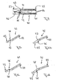
- Fig. 1 and 3 show cross-sections through functional elements of a distribution strip of the series 1000 RT, whereby details of the distribution strip of the series 1000 RT from the product catalog " Connection and Distribution Systems, Issue 1, pages 39 to 49, Corning Cable Systems GmbH & Co. KG, year 2000 " are known.
- the functional element 20 according to Fig. 1 designed as a separating element is designed as a switching element.
- Both functional elements 20, 21 of the 1000 RT series have in common that the same two contact springs 23, 24 accommodated in a housing 22, wherein each of the contact springs 23, 24 in the region of a front side 25 of the housing 22 formed as IDC contacts connecting elements 26 forms.
- the contact springs 23, 24 of the functional elements 20, 21 form contact points 27, which in the case of the functional element 20 formed as a separating element Fig. 1 touch and in the trained as a switching element functional element 21 of Fig. 3 with interposition of a web 28 are separated from each other and therefore do not touch.
- FIG. 1 A comparison of Fig. 1 and 3 can be immediately deduced that to provide different functional elements, namely according to Fig. 1 formed as a separating element functional element 20 and according to Fig. 3 designed as a switching element functional element 21, differently shaped, namely different lengths, contact springs 23, 24 must be kept.
- Fig. 2 shows a functional element 30 of a distribution strip of the 5000 series, with regard to technical details of the series 5000 on the product catalog " Connection and Distribution Systems, Task 1, pages 17 to 38, Corning Cable Systems GmbH & Co. KG, year 2000 "is referenced.
- the present invention is based on the problem of creating a novel functional element of a telecommunications system. This problem is solved by a functional element according to claim 1.
- cooperating, opposing contact springs at spaced-apart lateral sections which are positioned between the connection elements and the contact points of the contact springs, facing each other exhibitions, such that on the one hand starting from the back between the contact points of the contact springs as a separation device or test device or splitter device or on the other hand, both without first element introduced from the rear side and with the first element inserted from the rear side, starting from the front side between the exhibitions of the contact springs, a second one designed as a separating device or testing device or splinter device or protective device Element is insertable.
- the functional element according to the invention has a multiplicity of advantages.
- both a functional element designed as a separating element and a functional element designed as a switching element can be provided.
- both starting from the front of the housing as well as starting from the back of the housing a z.
- B. element designed as a protective device between the contact springs of the functional element By ensuring a simple structural design and using only two with respect to their structure identical contact springs therefore both a separating element and a switching element can be realized in which both from the front and from the back - and together or separately - a z. B. formed as a protective element element between the contact springs can be introduced.
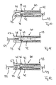
- Fig. 4 shows a cross section through a functional element 40 according to the invention of a telecommunications system, namely a cross section through a distribution strip in the region of a functional element 40 according to the invention.
- the functional element 40 has two contact springs 42 accommodated in a housing 41, which are of identical design, but are rotated by 180 ° in the housing 41.
- the contact springs 42 form on a front side 43 of the housing 41 preferably designed as IDC contacts connecting elements 44, which serve to connect cable wires of a subscriber cable and / or the system cable and / or jumper cable.
- the contact springs 42 Spaced apart from the connecting elements 44, the contact springs 42 form contact points 45, wherein in the case of Fig. 4 , in which the functional element 40 is designed as a separating element, the contact springs 42 touch in the region of the contact points 45.
- Each of the two mutually opposite, namely superimposed positioned, cooperating contact springs 42 has in an area between the respective connection element 44 and the respective contact point 45 via an exhibition 46.
- the displays 46 are positioned at spaced-apart lateral portions of the contact springs 42 and face each other.
- the formed on the two cooperating, superimposed contact springs 42 exhibitions 46 are formed such that the formed on the upper of the two contact springs 42 exhibition a first side portion, namely a viewed from the front side 43 from right lateral portion of the upper contact spring 42 assigned whereas the lower one of the two contact springs 42 associated with the exhibition 46 is associated with a second, namely seen from the front left side portion of the corresponding contact spring 42.
- the exhibitions 46 of the cooperating, superimposed positioned contact springs 42 face each other, but without the other of the two contact springs 42 to touch or contact.
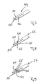
- the exhibitions 46 are designed as at about 90 ° relative to the contact spring 42 bent tabs 47.
- Fig. 6a, 6b show opposite Fig. 5a and 5b alternative contact springs 42, wherein the contact springs 42 differ only by the configuration of the exhibition 46.
- the exhibition 46 is designed as a bulge 48.
- the execution of Fig. 5a, 5b in which the exhibition 46 is formed as a bent tab 47, preferred.
- Fig. 10 shows the formed as a separating element contact element 40 of Fig. 4 together with an inserted from the front side 43 between the contact springs 41 element 49, which may be formed as a separator or test device or splitter device or protective device.
- element 49 which may be formed as a separator or test device or splitter device or protective device.
- Fig. 10 is a separator 49 inserted between the contact springs 42, as it Fig. 7 in solo view shows.
- the element 49 is formed or contoured so that the same when inserted between the two contact springs, the exhibitions 46 of both opposing contact springs 42 and thus deforms both contact springs 42, so that, as a comparison of Fig. 4 . 10 can be removed, the contact between the contact springs 42 in the region of the contact points 45 is canceled.
- the element 49 has two webs 51, 52 which are separated from each other by a slot 50, wherein each of the webs 51, 52 cooperates with a respective contact spring pair of a functional element. Accordingly, the element 49 can be inserted between the contact springs 42 of two functional elements positioned next to each other.
- Each web 51, 52 acts together with the exhibitions 46 of two opposing, superposed contact springs 42 of a functional element 40 together.
- Fig. 11 shows the trained as a separating element functional element 40 of Fig. 4 with an inserted from a rear side 53 between the two contact springs 42 element 54, wherein the element may be a splinter device or a protective device or a test device or a separator.
- the contact points 45 of both contact springs 42 are according to fig.11 on element 54.
- the introduced from the back 53 element 54 a separator and the introduced from the front side 43 element 54 z. B. be a protective element or splitter element.
- the introduced from the back 53 element 54 z. B. a protective element or splitter element and the introduced from the front 43 element 54 may be a separating element.
- the element 49 is designed such that when the same is inserted between the two superimposed contact springs 42, a web thereof at the exhibitions 46 of the two contact springs 42 comes to rest and therefore both contact springs 42 deformed.
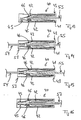
- Fig. 8 an alternative element 55 which is contoured such that, when inserted between the two contact springs 42, it contacts and deforms exclusively one exposition 46 of the two cooperating, opposing or superimposed contact springs, whereas the same traverses the exhibition of the other contact spring and not touched, so that the corresponding contact spring 42 is not deformed.
- Fig. 13 to 15 This can Fig. 13 to 15 be taken, in Fig. 13, 14th a web of the element 55 contacts the respective exhibition 46 of the lower contact spring 42 and thus deforms the lower contact spring 42, whereas the same circumvents the exhibition 46 of the upper contact spring and does not deform it.
- the element 55 is inserted with a different orientation between the two contact springs 42, so that a web of the element 55 comes to rest on the exhibition 46 of the upper contact spring 42 and thus the upper contact spring 42 deformed, whereas the lower contact spring is not deformed.
- Fig. 8 can be removed, for this purpose, the two webs 51, 52 of the element 55 exclusively on one side of a recess 56, wherein the depth of the recesses 56 is adapted to the width of the exhibitions 46 of the contact springs 42 so that the recesses 46 bypass it without touching can be.
- Fig. 9 shows a further alternative for a starting from the front side 43 of the functional element 40 between the contact springs 42 thereof insertable element 57, wherein the element 57 of the Fig. 9 is designed such that when it is inserted between the contact springs 42 of the functional element 40 starting from the front side 43, a web thereof the exhibitions 46 of the two cooperating, opposing or superimposed positioned contact springs 42 herumzt and therefore not touched. This will be on Fig. 16 directed.
- the webs 51, 52 of the element 57 are contoured on both sides with corresponding recesses 56.
- a web 51, 52 of the same between the contact points 45 of the contact springs 42 of a functional element 40 can be inserted, so as to separate the contact springs 42 in the region of the contact points 45 from each other.
- the only requirement is that, starting from the rear side 53, no further element is inserted between the contact points 45 of the opposing, cooperating contact springs 42.
- Fig. 17 shows the functional element 40 of Fig. 4 together with one of the front side 43 of the same between the contact springs 42 inserted element 55 according to Fig. 8 , unlike Fig. 15 the element 55 is inserted so far that it passes between the contact points 45 in such a way that it contacts the contact point 45 of one, namely the lower, contact spring 42, but does not touch the contact point 45 of the other, namely the upper, contact spring 42.
- Fig. 17 corresponds accordingly Fig. 16 with another element inserted from the front.
- a separation function for a contact spring can be realized or combined with a protective function for the other contact spring.
- FIGS. 18 and 19 show a functional element 40 according to the invention, which is designed as a switching element.
- a switching element functional element 40 of the Fig. 18 additionally comprises a web 58 positioned between the contact springs 42, which ensures that when neither an element is inserted between the contact springs 42 starting from the front side 43 nor from the rear side 53, the two contact springs 42 are in the region of their contact points 45 do not touch. According to Fig. 18 this web 58 extends in a region between the exhibitions 46 of the contact springs 42.
- Fig. 19 is between the contact springs 42 of the switching element designed as a functional element 40 of Fig. 18 the element 57 according to Fig. 9 inserted from the front side 43, wherein the element 57 in this state, both contact points 45 of the superimposed contact springs 42 contacted and so the in Fig. 18 existing electrical insulation of the two contact springs 42 cancels each other.
Landscapes
- Engineering & Computer Science (AREA)
- Computer Networks & Wireless Communication (AREA)
- Details Of Connecting Devices For Male And Female Coupling (AREA)
- Structure Of Telephone Exchanges (AREA)
Applications Claiming Priority (1)
| Application Number | Priority Date | Filing Date | Title |
|---|---|---|---|
| DE200720010607 DE202007010607U1 (de) | 2007-07-27 | 2007-07-27 | Funktionselement einer Telekommunikationsanlage |
Publications (3)
| Publication Number | Publication Date |
|---|---|
| EP2019451A2 true EP2019451A2 (fr) | 2009-01-28 |
| EP2019451A3 EP2019451A3 (fr) | 2012-03-07 |
| EP2019451B1 EP2019451B1 (fr) | 2013-11-06 |
Family
ID=38806392
Family Applications (1)
| Application Number | Title | Priority Date | Filing Date |
|---|---|---|---|
| EP20080010768 Not-in-force EP2019451B1 (fr) | 2007-07-27 | 2008-06-13 | Elément de fonction d'une installation de télécommunication |
Country Status (2)
| Country | Link |
|---|---|
| EP (1) | EP2019451B1 (fr) |
| DE (1) | DE202007010607U1 (fr) |
Family Cites Families (3)
| Publication number | Priority date | Publication date | Assignee | Title |
|---|---|---|---|---|
| DE2643150A1 (de) * | 1976-09-24 | 1978-03-30 | Siemens Ag | Verteileranordnung fuer fernmeldevermittlungsanlagen |
| US5575689A (en) * | 1995-05-17 | 1996-11-19 | Lucent Technologies Inc. | Connector modules |
| US7207818B1 (en) * | 2005-10-11 | 2007-04-24 | 3M Innovative Properties Company | Telecommunications assembly including at least one telecommunications module |
-
2007
- 2007-07-27 DE DE200720010607 patent/DE202007010607U1/de not_active Expired - Lifetime
-
2008
- 2008-06-13 EP EP20080010768 patent/EP2019451B1/fr not_active Not-in-force
Non-Patent Citations (3)
| Title |
|---|
| "Anschluss- und Verteilersysteme", 2000, CORNING CABLE SYSTEMS GMBH & CO. |
| "Anschluss- und Verteilersysteme", vol. 1, 2000, CORNING CABLE SYSTEMS GMBH & CO., pages: 17 - 38 |
| "Anschluss- und Verteilersysteme", vol. 1, 2000, pages: 39 - 49 |
Also Published As
| Publication number | Publication date |
|---|---|
| DE202007010607U1 (de) | 2007-12-06 |
| EP2019451B1 (fr) | 2013-11-06 |
| EP2019451A3 (fr) | 2012-03-07 |
Similar Documents
| Publication | Publication Date | Title |
|---|---|---|
| DE102011113333B4 (de) | Elektrische Reihenklemme und Reihenklemmenblock | |
| EP1921715A2 (fr) | Bornier, fiche de test et bloc de bornes d'essai | |
| EP3342005B1 (fr) | Bloc de jonction électrique | |
| DE102010051899A1 (de) | Elektrisches Klemmenbauelement | |
| DE2645325A1 (de) | Eingangsverbinder fuer telefonvermittlungen | |
| WO2010006673A2 (fr) | Module répartiteur pour l'informatique et les télécommunications | |
| EP3259807B1 (fr) | Bloc de jonction électrique | |
| DE102005042163B3 (de) | Schutzstecker für ein Anschlussmodul | |
| EP2507869B1 (fr) | Réglette de répartiteur | |
| DE102021128871A1 (de) | Steckverbinder, Steckverbinderanordnung, sowie ein Werkzeug und Verfahren zur Montage der Steckverbinderanordnung | |
| EP1557049B1 (fr) | Systeme de distribution pour installation de telecommunication et systeme de protection pour systeme de distribution | |
| EP1522126A1 (fr) | Dispositif de repartition d'installation de telecommunication | |
| EP2019451B1 (fr) | Elément de fonction d'une installation de télécommunication | |
| EP2193579B1 (fr) | Élément fonctionnel d'une installation de télécommunication | |
| WO2010142359A1 (fr) | Bornier | |
| WO2023180170A1 (fr) | Unité fonctionnelle comprenant un bornier électrique et une fiche | |
| EP2186347A1 (fr) | Élément fonctionnel d'un système de télécommunication | |
| DE102018127087B4 (de) | Elektrische Reihenklemme | |
| DE202008005934U1 (de) | Verteilerleiste einer Telekommunikationsanlage | |
| WO2015096969A1 (fr) | Bus de terre | |
| EP1380072B1 (fr) | Connecteur electrique | |
| DE102019133031B4 (de) | Stromverteileranordnung mit einem Entkopplungselement zur thermischen und mechanischen Entkopplung einer Sicherung von einer Stromschiene | |
| EP1391964A1 (fr) | Répartiteur électrique | |
| DE2449638C3 (de) | Tastatur | |
| DE202008007545U1 (de) | Verteilerleiste einer Telekommunikationsanlage |
Legal Events
| Date | Code | Title | Description |
|---|---|---|---|
| PUAI | Public reference made under article 153(3) epc to a published international application that has entered the european phase |
Free format text: ORIGINAL CODE: 0009012 |
|
| AK | Designated contracting states |
Kind code of ref document: A2 Designated state(s): AT BE BG CH CY CZ DE DK EE ES FI FR GB GR HR HU IE IS IT LI LT LU LV MC MT NL NO PL PT RO SE SI SK TR |
|
| AX | Request for extension of the european patent |
Extension state: AL BA MK RS |
|
| PUAL | Search report despatched |
Free format text: ORIGINAL CODE: 0009013 |
|
| AK | Designated contracting states |
Kind code of ref document: A3 Designated state(s): AT BE BG CH CY CZ DE DK EE ES FI FR GB GR HR HU IE IS IT LI LT LU LV MC MT NL NO PL PT RO SE SI SK TR |
|
| AX | Request for extension of the european patent |
Extension state: AL BA MK RS |
|
| RIC1 | Information provided on ipc code assigned before grant |
Ipc: H04Q 1/14 20060101ALI20120201BHEP Ipc: H01R 9/24 20060101AFI20120201BHEP |
|
| 17P | Request for examination filed |
Effective date: 20120905 |
|
| AKX | Designation fees paid |
Designated state(s): AT BE BG CH CY CZ DE DK EE ES FI FR GB GR HR HU IE IS IT LI LT LU LV MC MT NL NO PL PT RO SE SI SK TR |
|
| RIC1 | Information provided on ipc code assigned before grant |
Ipc: H01R 9/24 20060101AFI20130418BHEP Ipc: H04Q 1/14 20060101ALI20130418BHEP |
|
| GRAP | Despatch of communication of intention to grant a patent |
Free format text: ORIGINAL CODE: EPIDOSNIGR1 |
|
| INTG | Intention to grant announced |
Effective date: 20130527 |
|
| GRAS | Grant fee paid |
Free format text: ORIGINAL CODE: EPIDOSNIGR3 |
|
| GRAA | (expected) grant |
Free format text: ORIGINAL CODE: 0009210 |
|
| AK | Designated contracting states |
Kind code of ref document: B1 Designated state(s): AT BE BG CH CY CZ DE DK EE ES FI FR GB GR HR HU IE IS IT LI LT LU LV MC MT NL NO PL PT RO SE SI SK TR |
|
| REG | Reference to a national code |
Ref country code: GB Ref legal event code: FG4D Free format text: NOT ENGLISH |
|
| REG | Reference to a national code |
Ref country code: CH Ref legal event code: EP |
|
| REG | Reference to a national code |
Ref country code: AT Ref legal event code: REF Ref document number: 639984 Country of ref document: AT Kind code of ref document: T Effective date: 20131215 |
|
| REG | Reference to a national code |
Ref country code: IE Ref legal event code: FG4D Free format text: LANGUAGE OF EP DOCUMENT: GERMAN |
|
| REG | Reference to a national code |
Ref country code: DE Ref legal event code: R096 Ref document number: 502008010889 Country of ref document: DE Effective date: 20140102 |
|
| REG | Reference to a national code |
Ref country code: NL Ref legal event code: VDEP Effective date: 20131106 |
|
| REG | Reference to a national code |
Ref country code: LT Ref legal event code: MG4D |
|
| PG25 | Lapsed in a contracting state [announced via postgrant information from national office to epo] |
Ref country code: NL Free format text: LAPSE BECAUSE OF FAILURE TO SUBMIT A TRANSLATION OF THE DESCRIPTION OR TO PAY THE FEE WITHIN THE PRESCRIBED TIME-LIMIT Effective date: 20131106 Ref country code: FI Free format text: LAPSE BECAUSE OF FAILURE TO SUBMIT A TRANSLATION OF THE DESCRIPTION OR TO PAY THE FEE WITHIN THE PRESCRIBED TIME-LIMIT Effective date: 20131106 Ref country code: LT Free format text: LAPSE BECAUSE OF FAILURE TO SUBMIT A TRANSLATION OF THE DESCRIPTION OR TO PAY THE FEE WITHIN THE PRESCRIBED TIME-LIMIT Effective date: 20131106 Ref country code: SE Free format text: LAPSE BECAUSE OF FAILURE TO SUBMIT A TRANSLATION OF THE DESCRIPTION OR TO PAY THE FEE WITHIN THE PRESCRIBED TIME-LIMIT Effective date: 20131106 Ref country code: IS Free format text: LAPSE BECAUSE OF FAILURE TO SUBMIT A TRANSLATION OF THE DESCRIPTION OR TO PAY THE FEE WITHIN THE PRESCRIBED TIME-LIMIT Effective date: 20140306 Ref country code: NO Free format text: LAPSE BECAUSE OF FAILURE TO SUBMIT A TRANSLATION OF THE DESCRIPTION OR TO PAY THE FEE WITHIN THE PRESCRIBED TIME-LIMIT Effective date: 20140206 Ref country code: HR Free format text: LAPSE BECAUSE OF FAILURE TO SUBMIT A TRANSLATION OF THE DESCRIPTION OR TO PAY THE FEE WITHIN THE PRESCRIBED TIME-LIMIT Effective date: 20131106 |
|
| PG25 | Lapsed in a contracting state [announced via postgrant information from national office to epo] |
Ref country code: ES Free format text: LAPSE BECAUSE OF FAILURE TO SUBMIT A TRANSLATION OF THE DESCRIPTION OR TO PAY THE FEE WITHIN THE PRESCRIBED TIME-LIMIT Effective date: 20131106 Ref country code: LV Free format text: LAPSE BECAUSE OF FAILURE TO SUBMIT A TRANSLATION OF THE DESCRIPTION OR TO PAY THE FEE WITHIN THE PRESCRIBED TIME-LIMIT Effective date: 20131106 |
|
| PG25 | Lapsed in a contracting state [announced via postgrant information from national office to epo] |
Ref country code: PT Free format text: LAPSE BECAUSE OF FAILURE TO SUBMIT A TRANSLATION OF THE DESCRIPTION OR TO PAY THE FEE WITHIN THE PRESCRIBED TIME-LIMIT Effective date: 20140306 |
|
| PG25 | Lapsed in a contracting state [announced via postgrant information from national office to epo] |
Ref country code: EE Free format text: LAPSE BECAUSE OF FAILURE TO SUBMIT A TRANSLATION OF THE DESCRIPTION OR TO PAY THE FEE WITHIN THE PRESCRIBED TIME-LIMIT Effective date: 20131106 |
|
| REG | Reference to a national code |
Ref country code: DE Ref legal event code: R097 Ref document number: 502008010889 Country of ref document: DE |
|
| PG25 | Lapsed in a contracting state [announced via postgrant information from national office to epo] |
Ref country code: IT Free format text: LAPSE BECAUSE OF FAILURE TO SUBMIT A TRANSLATION OF THE DESCRIPTION OR TO PAY THE FEE WITHIN THE PRESCRIBED TIME-LIMIT Effective date: 20131106 Ref country code: PL Free format text: LAPSE BECAUSE OF FAILURE TO SUBMIT A TRANSLATION OF THE DESCRIPTION OR TO PAY THE FEE WITHIN THE PRESCRIBED TIME-LIMIT Effective date: 20131106 Ref country code: CZ Free format text: LAPSE BECAUSE OF FAILURE TO SUBMIT A TRANSLATION OF THE DESCRIPTION OR TO PAY THE FEE WITHIN THE PRESCRIBED TIME-LIMIT Effective date: 20131106 Ref country code: SK Free format text: LAPSE BECAUSE OF FAILURE TO SUBMIT A TRANSLATION OF THE DESCRIPTION OR TO PAY THE FEE WITHIN THE PRESCRIBED TIME-LIMIT Effective date: 20131106 Ref country code: RO Free format text: LAPSE BECAUSE OF FAILURE TO SUBMIT A TRANSLATION OF THE DESCRIPTION OR TO PAY THE FEE WITHIN THE PRESCRIBED TIME-LIMIT Effective date: 20131106 |
|
| PLBE | No opposition filed within time limit |
Free format text: ORIGINAL CODE: 0009261 |
|
| STAA | Information on the status of an ep patent application or granted ep patent |
Free format text: STATUS: NO OPPOSITION FILED WITHIN TIME LIMIT |
|
| PG25 | Lapsed in a contracting state [announced via postgrant information from national office to epo] |
Ref country code: DK Free format text: LAPSE BECAUSE OF FAILURE TO SUBMIT A TRANSLATION OF THE DESCRIPTION OR TO PAY THE FEE WITHIN THE PRESCRIBED TIME-LIMIT Effective date: 20131106 |
|
| 26N | No opposition filed |
Effective date: 20140807 |
|
| REG | Reference to a national code |
Ref country code: DE Ref legal event code: R097 Ref document number: 502008010889 Country of ref document: DE Effective date: 20140807 |
|
| PG25 | Lapsed in a contracting state [announced via postgrant information from national office to epo] |
Ref country code: MC Free format text: LAPSE BECAUSE OF FAILURE TO SUBMIT A TRANSLATION OF THE DESCRIPTION OR TO PAY THE FEE WITHIN THE PRESCRIBED TIME-LIMIT Effective date: 20131106 Ref country code: LU Free format text: LAPSE BECAUSE OF FAILURE TO SUBMIT A TRANSLATION OF THE DESCRIPTION OR TO PAY THE FEE WITHIN THE PRESCRIBED TIME-LIMIT Effective date: 20140613 |
|
| GBPC | Gb: european patent ceased through non-payment of renewal fee |
Effective date: 20140613 |
|
| PG25 | Lapsed in a contracting state [announced via postgrant information from national office to epo] |
Ref country code: SI Free format text: LAPSE BECAUSE OF FAILURE TO SUBMIT A TRANSLATION OF THE DESCRIPTION OR TO PAY THE FEE WITHIN THE PRESCRIBED TIME-LIMIT Effective date: 20131106 |
|
| REG | Reference to a national code |
Ref country code: IE Ref legal event code: MM4A |
|
| PG25 | Lapsed in a contracting state [announced via postgrant information from national office to epo] |
Ref country code: IE Free format text: LAPSE BECAUSE OF NON-PAYMENT OF DUE FEES Effective date: 20140613 |
|
| PG25 | Lapsed in a contracting state [announced via postgrant information from national office to epo] |
Ref country code: GB Free format text: LAPSE BECAUSE OF NON-PAYMENT OF DUE FEES Effective date: 20140613 |
|
| REG | Reference to a national code |
Ref country code: AT Ref legal event code: MM01 Ref document number: 639984 Country of ref document: AT Kind code of ref document: T Effective date: 20140613 |
|
| PG25 | Lapsed in a contracting state [announced via postgrant information from national office to epo] |
Ref country code: AT Free format text: LAPSE BECAUSE OF NON-PAYMENT OF DUE FEES Effective date: 20140613 |
|
| PG25 | Lapsed in a contracting state [announced via postgrant information from national office to epo] |
Ref country code: MT Free format text: LAPSE BECAUSE OF FAILURE TO SUBMIT A TRANSLATION OF THE DESCRIPTION OR TO PAY THE FEE WITHIN THE PRESCRIBED TIME-LIMIT Effective date: 20131106 |
|
| PG25 | Lapsed in a contracting state [announced via postgrant information from national office to epo] |
Ref country code: BG Free format text: LAPSE BECAUSE OF FAILURE TO SUBMIT A TRANSLATION OF THE DESCRIPTION OR TO PAY THE FEE WITHIN THE PRESCRIBED TIME-LIMIT Effective date: 20131106 |
|
| REG | Reference to a national code |
Ref country code: FR Ref legal event code: PLFP Year of fee payment: 9 |
|
| PG25 | Lapsed in a contracting state [announced via postgrant information from national office to epo] |
Ref country code: GR Free format text: LAPSE BECAUSE OF FAILURE TO SUBMIT A TRANSLATION OF THE DESCRIPTION OR TO PAY THE FEE WITHIN THE PRESCRIBED TIME-LIMIT Effective date: 20140207 Ref country code: CY Free format text: LAPSE BECAUSE OF FAILURE TO SUBMIT A TRANSLATION OF THE DESCRIPTION OR TO PAY THE FEE WITHIN THE PRESCRIBED TIME-LIMIT Effective date: 20131106 |
|
| PG25 | Lapsed in a contracting state [announced via postgrant information from national office to epo] |
Ref country code: HU Free format text: LAPSE BECAUSE OF FAILURE TO SUBMIT A TRANSLATION OF THE DESCRIPTION OR TO PAY THE FEE WITHIN THE PRESCRIBED TIME-LIMIT; INVALID AB INITIO Effective date: 20080613 Ref country code: BE Free format text: LAPSE BECAUSE OF FAILURE TO SUBMIT A TRANSLATION OF THE DESCRIPTION OR TO PAY THE FEE WITHIN THE PRESCRIBED TIME-LIMIT Effective date: 20140630 Ref country code: TR Free format text: LAPSE BECAUSE OF FAILURE TO SUBMIT A TRANSLATION OF THE DESCRIPTION OR TO PAY THE FEE WITHIN THE PRESCRIBED TIME-LIMIT Effective date: 20131106 |
|
| REG | Reference to a national code |
Ref country code: FR Ref legal event code: PLFP Year of fee payment: 10 |
|
| REG | Reference to a national code |
Ref country code: FR Ref legal event code: PLFP Year of fee payment: 11 |
|
| PGFP | Annual fee paid to national office [announced via postgrant information from national office to epo] |
Ref country code: FR Payment date: 20180516 Year of fee payment: 11 |
|
| PGFP | Annual fee paid to national office [announced via postgrant information from national office to epo] |
Ref country code: DE Payment date: 20190515 Year of fee payment: 12 |
|
| PGFP | Annual fee paid to national office [announced via postgrant information from national office to epo] |
Ref country code: CH Payment date: 20190425 Year of fee payment: 12 |
|
| PG25 | Lapsed in a contracting state [announced via postgrant information from national office to epo] |
Ref country code: FR Free format text: LAPSE BECAUSE OF NON-PAYMENT OF DUE FEES Effective date: 20190630 |
|
| REG | Reference to a national code |
Ref country code: DE Ref legal event code: R119 Ref document number: 502008010889 Country of ref document: DE |
|
| REG | Reference to a national code |
Ref country code: CH Ref legal event code: PL |
|
| PG25 | Lapsed in a contracting state [announced via postgrant information from national office to epo] |
Ref country code: CH Free format text: LAPSE BECAUSE OF NON-PAYMENT OF DUE FEES Effective date: 20200630 Ref country code: LI Free format text: LAPSE BECAUSE OF NON-PAYMENT OF DUE FEES Effective date: 20200630 |
|
| PG25 | Lapsed in a contracting state [announced via postgrant information from national office to epo] |
Ref country code: DE Free format text: LAPSE BECAUSE OF NON-PAYMENT OF DUE FEES Effective date: 20210101 |