EP2019291B1 - Corps doté d'une mise à l'échelle d'angle et son utilisation - Google Patents
Corps doté d'une mise à l'échelle d'angle et son utilisation Download PDFInfo
- Publication number
- EP2019291B1 EP2019291B1 EP08007801A EP08007801A EP2019291B1 EP 2019291 B1 EP2019291 B1 EP 2019291B1 EP 08007801 A EP08007801 A EP 08007801A EP 08007801 A EP08007801 A EP 08007801A EP 2019291 B1 EP2019291 B1 EP 2019291B1
- Authority
- EP
- European Patent Office
- Prior art keywords
- annular body
- angular scale
- machine part
- recesses
- recess
- Prior art date
- Legal status (The legal status is an assumption and is not a legal conclusion. Google has not performed a legal analysis and makes no representation as to the accuracy of the status listed.)
- Active
Links
- 230000005291 magnetic effect Effects 0.000 claims description 8
- 238000005520 cutting process Methods 0.000 claims description 5
- 210000003746 feather Anatomy 0.000 claims description 4
- 230000007704 transition Effects 0.000 claims description 4
- 230000005294 ferromagnetic effect Effects 0.000 description 4
- 238000000034 method Methods 0.000 description 3
- XEEYBQQBJWHFJM-UHFFFAOYSA-N Iron Chemical compound [Fe] XEEYBQQBJWHFJM-UHFFFAOYSA-N 0.000 description 2
- 229910000831 Steel Inorganic materials 0.000 description 2
- 230000000694 effects Effects 0.000 description 2
- 239000000463 material Substances 0.000 description 2
- 230000003287 optical effect Effects 0.000 description 2
- 239000010959 steel Substances 0.000 description 2
- VYZAMTAEIAYCRO-UHFFFAOYSA-N Chromium Chemical compound [Cr] VYZAMTAEIAYCRO-UHFFFAOYSA-N 0.000 description 1
- ZOKXTWBITQBERF-UHFFFAOYSA-N Molybdenum Chemical compound [Mo] ZOKXTWBITQBERF-UHFFFAOYSA-N 0.000 description 1
- 238000002679 ablation Methods 0.000 description 1
- 239000000956 alloy Substances 0.000 description 1
- 229910045601 alloy Inorganic materials 0.000 description 1
- 229910052804 chromium Inorganic materials 0.000 description 1
- 239000011651 chromium Substances 0.000 description 1
- 229910017052 cobalt Inorganic materials 0.000 description 1
- 239000010941 cobalt Substances 0.000 description 1
- GUTLYIVDDKVIGB-UHFFFAOYSA-N cobalt atom Chemical compound [Co] GUTLYIVDDKVIGB-UHFFFAOYSA-N 0.000 description 1
- 230000001419 dependent effect Effects 0.000 description 1
- 238000009826 distribution Methods 0.000 description 1
- 238000004049 embossing Methods 0.000 description 1
- 229910052742 iron Inorganic materials 0.000 description 1
- 239000000696 magnetic material Substances 0.000 description 1
- 230000005415 magnetization Effects 0.000 description 1
- 229910052751 metal Inorganic materials 0.000 description 1
- 239000002184 metal Substances 0.000 description 1
- 229910052750 molybdenum Inorganic materials 0.000 description 1
- 239000011733 molybdenum Substances 0.000 description 1
- 238000005457 optimization Methods 0.000 description 1
- 229910000679 solder Inorganic materials 0.000 description 1
Images

Classifications
-
- G—PHYSICS
- G01—MEASURING; TESTING
- G01D—MEASURING NOT SPECIALLY ADAPTED FOR A SPECIFIC VARIABLE; ARRANGEMENTS FOR MEASURING TWO OR MORE VARIABLES NOT COVERED IN A SINGLE OTHER SUBCLASS; TARIFF METERING APPARATUS; MEASURING OR TESTING NOT OTHERWISE PROVIDED FOR
- G01D5/00—Mechanical means for transferring the output of a sensing member; Means for converting the output of a sensing member to another variable where the form or nature of the sensing member does not constrain the means for converting; Transducers not specially adapted for a specific variable
- G01D5/26—Mechanical means for transferring the output of a sensing member; Means for converting the output of a sensing member to another variable where the form or nature of the sensing member does not constrain the means for converting; Transducers not specially adapted for a specific variable characterised by optical transfer means, i.e. using infrared, visible, or ultraviolet light
- G01D5/32—Mechanical means for transferring the output of a sensing member; Means for converting the output of a sensing member to another variable where the form or nature of the sensing member does not constrain the means for converting; Transducers not specially adapted for a specific variable characterised by optical transfer means, i.e. using infrared, visible, or ultraviolet light with attenuation or whole or partial obturation of beams of light
- G01D5/34—Mechanical means for transferring the output of a sensing member; Means for converting the output of a sensing member to another variable where the form or nature of the sensing member does not constrain the means for converting; Transducers not specially adapted for a specific variable characterised by optical transfer means, i.e. using infrared, visible, or ultraviolet light with attenuation or whole or partial obturation of beams of light the beams of light being detected by photocells
- G01D5/347—Mechanical means for transferring the output of a sensing member; Means for converting the output of a sensing member to another variable where the form or nature of the sensing member does not constrain the means for converting; Transducers not specially adapted for a specific variable characterised by optical transfer means, i.e. using infrared, visible, or ultraviolet light with attenuation or whole or partial obturation of beams of light the beams of light being detected by photocells using displacement encoding scales
Definitions
- the invention relates to a body with an angle scaling according to claim 1, as it can be used in particular in angle measuring systems.
- the invention relates to a use of the body with an angle scaling for measuring the rotational position on a high-speed shaft of a machine tool according to claim 10.
- Such angle measuring systems are used to measure rotational movements or rotational positions of a machine part, such as a shaft on which then a body with an angular scaling is fixed in rotation.
- the angle scaling can have, for example, an optical or a magnetic division, which can be scanned accordingly.
- the rotational movement is either incremental or absolute, the output measured value is z.
- B. a sequence of counts, a counter value or a code word.
- Corresponding angle measuring systems are used particularly in machine tools on high-speed spindles. Such spindles are increasingly being operated at high speeds, for example up to more than 40,000 revolutions per minute, in order to achieve high-quality workpiece surfaces, for example by means of cutting machine tools. Correspondingly large is the mechanical load of rotating parts which are mounted on such a spindle.
- those are usually annular body with an angle scaling, in particular with a magnetic division, rotatably connected to the spindles so that they are exposed to enormous centrifugal forces. It is a permanent goal to design bodies with angular scaling which withstand the stresses due to high speeds, and which have the required fatigue strength especially under these loads. These requirements are not least due to safety considerations.
- the invention is based on a prior art, as described for example in the patent US 4257040 is disclosed. There, a body is shown with an angle scaling, which is positively fastened as a rotating element on a shaft.
- Such a design of the rotating body with an angle scaling has the disadvantage that its permissible maximum speed at high speeds, as they occur in high-speed machine parts, especially waves, is not sufficiently large or its fatigue strength is not given.
- the invention is therefore based on the object to provide a body with an angle scaling for measuring the rotational position of a machine part, which is characterized in particular by the fact that it is suitable for extremely high maximum speeds.
- the invention is also based on the object to measure the rotational position of a high-speed shaft of a machine tool.
- the annular body according to the invention is suitable with an angle scaling for measuring the rotational position of a machine part about an axis.
- the body has on its inner circumference radial recesses and elevations. At least one of the recesses is for positive fit rotationally fixed attachment to the machine part suitable. Furthermore, the sum of the central angles, which are respectively defined by start and end points of the elevations, is smaller than the sum of the central angles, which are respectively defined by start and end points of the recesses.
- centering angle is to be understood as meaning, in particular, a midpoint angle about a point on the axis within the annular body.
- the annular body is designed with an angle scaling so that the sum of the central angles, which are respectively defined by start and end points of the recesses greater than 220 °, in particular greater than 240 °, advantageously greater than 270 ° or 300 °.
- the at least one recess for the positive rotationally fixed attachment to the machine part having a geometry with a smallest contour radius Ry.
- Another recess has a smallest contour radius Rx, so that the condition Ry ⁇ Rx is satisfied.
- the further recess is then often not used to transmit torque from the machine part to the body, but is designed only to increase the allowable speed or to increase the fatigue strength.
- the recess in question has a plurality of contour radii for the form-fitting, rotationally fixed attachment to the machine part, in particular the smallest contour radius Ry is relevant here. But it may also be that the recess for the positive rotationally fixed attachment to the machine part only has a contour radius Ry, for example, if the recess in question is designed semicircular, for receiving a in cross-section round pin. In this case, then the (only) contour radius Ry is decisive.
- the annular body may be constructed with an angle scaling such that the smallest distance between the bottom of the recess for positive rotationally fixed attachment to the machine part of the body and the axis is less than or equal to the smallest distance between the bottom of one of the further recess and the axis is.
- the smallest distance means the shortest distance to the axis, so that the distance from the axis to the point whose distance is determined, is aligned orthogonal to the axis.
- the bottom of the further recess is that geometric area which is furthest from the axis within the recess.
- the ratio of the outer radius of the body to its inner radius is less than 2, in particular less than 2.25 or 1.75. Because especially with such slim annular bodies, the material stress is always very high.
- the annular body is designed so that its angular scaling is arranged on the shell side of the body.
- the invention also includes bodies on the front side of which an angle scaling is arranged, for example with radially oriented graduation or division structures.
- the body is monolithic.
- monolithic is to be understood below that a so-called body consists of one piece, so that it can be made for example by a metal-cutting process, for example, from a steel material. Due to the monolithic design, the permissible maximum speed can be positively influenced.
- the angle scaling may be attached as a separate ring to the annular body, or applied directly to or on the body.
- the angle scaling can be made up of magnetic regions generated directly by appropriate magnetization of the body.
- a direct application of an angle scaling on the annular body can also be carried out, for example, with a laser Abladier process.
- the outer shell side of the body is coated with a special layer and then made a single-coat ablation. Accordingly, the angle scaling can then be scanned with an optical principle.
- an angle scaling can be applied directly to the body.
- the angle scaling is fixed alternatively as a separate ring on the annular body, in particular if a special magnetic material is used for this ring, in which a magnetic division structure is produced with large field strengths.
- the recess for the positive rotationally fixed attachment of the body to the machine part as a keyway be configured for a disc spring, insert key or sliding spring.
- the positive non-rotatable attachment of the body to the machine part with a Dahlnutprofil or a pin connection can be produced.
- a fast-running wave is to be understood as waves that can rotate with at least 10,000, in particular at least 20,000, or at least 30,000 revolutions per minute during operation.
- the machine tool is a cutting machine, because such machine tools often have extremely high maximum speeds of rotation of the spindle. Accordingly, the wave is advantageous to which the annular body is fixed, coupled to a cutting tool.
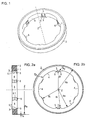
- the corresponding body 1, 1 ' has on its inner circumference two recesses for the form-fitting, rotationally fixed attachment to a machine part, here on a shaft 8.
- these recesses are designed as keyways 3 according to DIN 6885, into which a feather key 7 is incorporated become can:
- the annular body 1, 1 'and the shaft 8 are rotatable about a central axis Z.
- the annular body 1 is provided with a shell-side angle scaling 2.
- the angle scaling 2 has a magnetic division, in particular here a separate ferromagnetic ring is used with circumferentially alternately magnetized areas.
- the ferromagnetic ring is made, for example, of an alloy having the components iron, chromium, cobalt and molybdenum, while the body 1 is made of a high-strength bearing steel. In this case, the ferromagnetic ring is fixed to the body 1, 1 'shell side by a solder joint.
- the angle scaling 2 is designed such that a rotational position about an axis Z of the body 1, 1 'is detectable, that is to say that the magnetic markings of the angular scaling 2 have an offset in the circumferential or rotational direction when the annular body rotates about the axis Z ,
- the angle scaling 2 is designed such that a magnetic scanning of the angle scaling 2 by a magneto-sensitive scanning head is possible.
- the body 1 on its inner circumference next to the keyways 3 more recesses 4. These are not used for attachment to the shaft 8, but are provided only for reasons of increasing the permissible speed or the continuous load capacity of the body 1.
- This centering collar 5.1 is processed very precisely and serves as a contact surface to the shaft 8.
- elevations 6 are provided between the individual recesses 4 on the inner circumference. These surveys 6 have also axially in each case a precisely machined Centering collar 6.1. Accordingly, the shaft 8 is in the installed state of the centering 5.1, 6.1 along an interrupted service line.
- central angles ⁇ , ⁇ can be used, which in the present case describes the angle between two straight lines directed radially outward from the axis Z, which are defined by defined starting points S ⁇ 1 to S ⁇ 8 , S ⁇ 1 to S ⁇ 8 and end points E ⁇ 1, respectively until E ⁇ 8 , E ⁇ 1 to E ⁇ 8 run on the inner circumference of the body 1.
- start and end points S ⁇ 1 to S ⁇ 8 , S ⁇ 1 to S ⁇ 8 , E ⁇ 1 to E ⁇ 8 , E ⁇ 1 to E ⁇ 8 in the FIG. 3 renounced, so in the FIG.
- starting points S ⁇ 1 to S ⁇ 8 , S ⁇ 1 to S ⁇ 8 always come to rest on end points E ⁇ 1 to E ⁇ 8 , E ⁇ 1 to E ⁇ 8 .
- the end point E ⁇ 2 is at the starting point S ⁇ 3 .
- the first group comprises the central angles ⁇ i , which are respectively defined by starting points S ⁇ i and end points E ⁇ i , at the keyways 3 and the recesses 4.
- the second group then comprises central angles ⁇ i , which are respectively defined by start and end points S ⁇ i , E ⁇ i of the elevations 5, 6.
- start and end points S ⁇ i , E ⁇ i are respectively defined by start and end points S ⁇ i , E ⁇ i of the elevations 5, 6.
- the starting points S ⁇ i , S ⁇ i , and endpoints E ⁇ i , E ⁇ i simultaneously those points at which there is a transition with respect to the concern and non-concern of the shaft 8 on the body 1.
- the feather key grooves 3 and the recesses 4 are therefore located between the starting points S ⁇ i and the end points E ⁇ i , while the elevations 5, 6 lie between the starting points S ⁇ i and the end points E ⁇ i .
- S ⁇ 1 to S ⁇ 8 there is also an end point E ⁇ 1 to E ⁇ 8 , E ⁇ 1 to E ⁇ 8 .
- the point E ⁇ 2 is congruent with S ⁇ 3 , as in the FIG. 3 shown.
- the sizes of the central angles ⁇ i of the second group are therefore derived from the respective length of the arc along which the shaft 8 rests against one of the elevations 5, 6 and the inner radius Ri.
- the central angles ⁇ 2 , ⁇ 5 , ⁇ 6 also have the value 2 °.
- the sum of the central angles ⁇ i which are respectively defined by start and end points S ⁇ i , E ⁇ i of the elevations 5, 6 at 56 °. From this, the sum of the central angles ⁇ i , which are respectively defined by start and end points S ⁇ i , E ⁇ i at the keyway grooves 3 and the recesses 4, can be determined.
- the central angles ⁇ 1 and ⁇ 5 are in each case 8 ° and the central angles ⁇ 2 , ⁇ 3 , ⁇ 4 , ⁇ 6 , ⁇ 7 and ⁇ 8 are each 48 °.
- the geometry of the body 1 has been dimensioned accordingly.
- the design of the individual radii Ra, Rn, Ri, Ry and Rx is in this context for the optimization of the permissible speed of importance.
- the invention is particularly advantageous in the case of comparatively slender annular bodies 1.
- the ratio of Ra to Ri is about 1.34.
- the permissible maximum speed can be increased when the recesses 4 are generated on the body 1.
- the radial extent of the annular body is reduced compared to prior art designs.
- the distance Df between the bottom of the keyways 3 and the axis Z is 29.3 mm smaller than the radius Rn between the bottom of the further recesses 4 and the axis Z, since Rn here is 30.1 mm. Accordingly, therefore, the keyways 3 do not penetrate into the annular region of the body 1, which is bounded inwardly by the radius Rn. Accordingly, the mechanical stresses in the operation of the body 1 in a geometric annular region, which is bounded by the radius Rn inwardly, very evenly, so that the maximum amplitudes of voltage spikes are minimized.
- the keyways 3 are bounded in the circumferential direction by parallel webs and in the radial direction by the bottom of the keyways 3.
- the transition between the bottom of the keyway grooves 3 to the webs has a roughness R z of 25 microns and a relatively small contour radius Ry, which is in the illustrated embodiment, 0.175 mm. Therefore, comparatively large voltage peaks due to notch effects are to be expected there. So that nevertheless a high permissible rotational speed is made possible, the smallest contour radii Rx, which for the transition to the radius Rn, which defines the base of the recess 4, are dimensioned comparatively large, in this case 5 mm. This results in a ratio Rx / Ry of approximately 28.6.
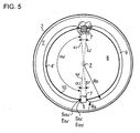
- FIG. 5 a second embodiment of a body 1 'according to the invention is shown.
- An essential difference from the subject of the first embodiment is that now only two circumferentially comparatively long recesses 4 'are provided.
- the segments 9 contribute to the centering of the shaft 8 and can additionally still have a dampening effect.
- practically no tangential stresses are transmitted through the segment 9 into the supporting body 1 ', so that here too there is a largely homogeneous stress curve, in particular in that annular region of the body 1', which is bounded inwardly by the radius Ri.
- the summation value ( ⁇ 1 '+ ⁇ 2 ' + ⁇ 3 '+ ⁇ 4 ') is obviously much smaller than ( ⁇ 1 '+ ⁇ 2 ' + ⁇ 3 '+ ⁇ 4 '), so that here too the condition ⁇ i ' ⁇ i ' is fulfilled.
- the segments 9 may also be designed as metal parts. In this case, it is also avoided that disturbing tangential stresses are introduced into the body 1 'by the segments 9, in particular by a parting line between the segments 9 and the body 1'.
- the body 1 ' may also have only one keyway 3, so that a segment 9 now only a recess 4' fills.
Landscapes
- Physics & Mathematics (AREA)
- General Physics & Mathematics (AREA)
- Transmission And Conversion Of Sensor Element Output (AREA)
- Rolling Contact Bearings (AREA)
- Machine Tool Sensing Apparatuses (AREA)
- Measurement Of Length, Angles, Or The Like Using Electric Or Magnetic Means (AREA)
Claims (11)
- Corps annulaire (1, 1') doté d'une échelle angulaire (2) et destiné à mesurer la position de rotation d'une partie (8) d'une machine autour d'un axe (Z),
le corps (1, 1') présentant à sa périphérie intérieure des découpes radiales (3, 4, 4') et des saillies radiales (5, 6),
au moins l'une des découpes (3) convenant pour être fixée en correspondance géométrique et à rotation solidaire sur la partie (8) de la machine,
caractérisé en ce que
la somme des angles au centre (εi, εi',) qui sont chacun définis par le point initial et le point final (Sεi, Eεi, Sεi', Eεi') des saillies (5, 6) est plus petite que la somme des angles au centre (αi, αi') qui sont chacun définis par les points initiaux et les points finaux (Sαi, Eαi, Sαi', Eαi') des découpes (3, 4, 4'), les points initiaux et les points finaux (Sεi, Eεi, Sεi', Eεi'; Sαi, Eαi, Sαi', Eαi') étant en même temps les points sur lesquels une transition entre l'application et la non application de la partie (8) de la machine sur le corps (1, 1') a lieu correctement. - Corps annulaire (1, 1') doté d'une échelle angulaire (2) selon la revendication 1, caractérisé en ce que la somme des angles au centre (αi, αi') qui sont chacun définis par des points initiaux et des points finaux (Sαi, Eαi, Sαi', Eαi') des découpes (3, 4, 4') est plus grande que 240° et en particulier plus grande que 300°.
- Corps annulaire (1, 1') doté d'une échelle angulaire (2) selon les revendications 1 ou 2, caractérisé en ce que la ou les découpes (3) destinées à être fixées en correspondance géométrique et à rotation solidaire sur la partie (8) de la machine présentent une géométrie dans laquelle le plus petit rayon du contour est Ry et une autre découpe (4, 4') une géométrie dans laquelle le plus petit rayon du contour est Rx, avec la condition Ry < Rx.
- Corps annulaire (1, 1') doté d'une échelle angulaire (2) selon l'une des revendications précédentes, caractérisé en ce que la plus petite distance (Df) entre le fond de la découpe (3) destinée à être fixée en correspondance géométrique et à rotation solidaire sur la partie (8) de la machine du corps (1, 1') et l'axe (Z) est inférieure ou égale à la plus petite distance (Rn) entre le fond d'une autre découpe (4, 4') et l'axe (Z).
- Corps annulaire (1, 1') doté d'une échelle angulaire (2) selon l'une des revendications précédentes, caractérisé en ce que le rapport entre le rayon extérieur (Ra) du corps (1, 1') et son rayon intérieur (Ri) est inférieur à 2,25 et en particulier inférieur à 1,75.
- Corps annulaire (1, 1') doté d'une échelle angulaire (2) selon l'une des revendications précédentes, caractérisé en ce que l'échelle angulaire (2) est disposée sur le côté d'enveloppe du corps (1, 1').
- Corps annulaire (1, 1') doté d'une échelle angulaire (2) selon l'une des revendications précédentes, caractérisé en ce que l'échelle angulaire (2) est fixée en tant qu'anneau séparé sur le corps annulaire (1, 1').
- Corps annulaire (1, 1') doté d'une échelle angulaire (2) selon l'une des revendications précédentes, caractérisé en ce que l'échelle angulaire (2) est constituée de zones magnétiques.
- Corps annulaire (1, 1') doté d'une échelle angulaire (2) selon l'une des revendications précédentes, caractérisé en ce que la découpe (3) destinée à assurer la fixation en correspondance géométrique et à rotation solidaire sur la partie (8) de la machine du corps (1, 1') est configurée comme rainure pour ressort d'adaptation.
- Utilisation d'un corps annulaire (1, 1') doté d'une échelle angulaire (2) selon l'une des revendications 1 à 9 sur un arbre (8) tournant rapidement d'une machine-outil en vue de mesurer la position de rotation de l'arbre (8).
- Utilisation d'un corps annulaire (1, 1') doté d'une échelle angulaire (2) selon la revendication 10, dans laquelle un outil d'enlèvement de matière peut être accouplé à l'arbre (8).
Applications Claiming Priority (1)
| Application Number | Priority Date | Filing Date | Title |
|---|---|---|---|
| DE102007034640A DE102007034640A1 (de) | 2007-07-23 | 2007-07-23 | Körper mit einer Winkelskalierung und dessen Verwendung |
Publications (2)
| Publication Number | Publication Date |
|---|---|
| EP2019291A1 EP2019291A1 (fr) | 2009-01-28 |
| EP2019291B1 true EP2019291B1 (fr) | 2012-08-15 |
Family
ID=39952208
Family Applications (1)
| Application Number | Title | Priority Date | Filing Date |
|---|---|---|---|
| EP08007801A Active EP2019291B1 (fr) | 2007-07-23 | 2008-04-23 | Corps doté d'une mise à l'échelle d'angle et son utilisation |
Country Status (5)
| Country | Link |
|---|---|
| US (1) | US7707730B2 (fr) |
| EP (1) | EP2019291B1 (fr) |
| JP (1) | JP5331400B2 (fr) |
| CN (1) | CN101354247B (fr) |
| DE (1) | DE102007034640A1 (fr) |
Families Citing this family (3)
| Publication number | Priority date | Publication date | Assignee | Title |
|---|---|---|---|---|
| DE102007034640A1 (de) * | 2007-07-23 | 2009-01-29 | Dr. Johannes Heidenhain Gmbh | Körper mit einer Winkelskalierung und dessen Verwendung |
| DE102012212698A1 (de) | 2012-07-19 | 2014-01-23 | Dr. Johannes Heidenhain Gmbh | Maßverkörperung, Verfahren zur Herstellung und Verwendung einer Maßverkörperung |
| US9594090B2 (en) | 2015-04-10 | 2017-03-14 | Ford Global Technologies, Llc | Press-fit tone wheel for a speed-sensing apparatus |
Family Cites Families (13)
| Publication number | Priority date | Publication date | Assignee | Title |
|---|---|---|---|---|
| JPS54143665A (en) | 1978-04-28 | 1979-11-09 | Nippon Denso Co Ltd | Rotation information detector of engines |
| DE69004131T2 (de) * | 1989-01-17 | 1994-03-24 | Alsthom Gec | Vorrichtung zur Ermittlung der Lage einer mit einem elektrisch diskontinuierlich leitenden Band umgebenen rotierenden Stahlwelle sowie Verfahren zur Herstellung des Bandes. |
| US5166611A (en) * | 1992-01-08 | 1992-11-24 | Production Research, Inc. | Tone wheel with coined serrations for engaging an annular support surface and method of assembling same on a wheel bearing seal |
| DE19632766A1 (de) * | 1996-08-14 | 1998-02-19 | Preh Elektro Feinmechanik | Drehwinkelsensor zur Drehwinkelanzeige mehrerer Umdrehungen einer Welle |
| JPH10325741A (ja) * | 1997-05-23 | 1998-12-08 | Matsushita Electric Ind Co Ltd | ロータリーエンコーダの回転体 |
| JP4063483B2 (ja) * | 2000-07-24 | 2008-03-19 | アルプス電気株式会社 | 回転型エンコーダ |
| JP4078147B2 (ja) * | 2002-08-13 | 2008-04-23 | キヤノン株式会社 | 回転角度検出装置及びその回転ディスク |
| JP2004077318A (ja) * | 2002-08-20 | 2004-03-11 | Uchiyama Mfg Corp | 磁気エンコーダ |
| DE10311098B4 (de) * | 2003-03-07 | 2016-06-30 | Dr. Johannes Heidenhain Gmbh | Winkelmesseinrichtung und Verfahren zur Herstellung der Winkelmesseinrichtung |
| KR20060107516A (ko) * | 2003-10-24 | 2006-10-13 | 가부시키가이샤 야스카와덴키 | 자기식 인코더 장치 및 액츄에이터 |
| DE102004056671A1 (de) * | 2004-11-24 | 2006-06-01 | Dr. Johannes Heidenhain Gmbh | Körper mit einer Winkelskalierung |
| JP4868753B2 (ja) * | 2005-03-18 | 2012-02-01 | ハイデンハイン株式会社 | 多回転型エンコーダおよびその製造方法 |
| DE102007034640A1 (de) * | 2007-07-23 | 2009-01-29 | Dr. Johannes Heidenhain Gmbh | Körper mit einer Winkelskalierung und dessen Verwendung |
-
2007
- 2007-07-23 DE DE102007034640A patent/DE102007034640A1/de not_active Withdrawn
-
2008
- 2008-04-23 EP EP08007801A patent/EP2019291B1/fr active Active
- 2008-07-18 US US12/175,781 patent/US7707730B2/en active Active
- 2008-07-22 JP JP2008188172A patent/JP5331400B2/ja active Active
- 2008-07-23 CN CN2008101341722A patent/CN101354247B/zh active Active
Also Published As
| Publication number | Publication date |
|---|---|
| CN101354247B (zh) | 2012-07-04 |
| US7707730B2 (en) | 2010-05-04 |
| CN101354247A (zh) | 2009-01-28 |
| DE102007034640A1 (de) | 2009-01-29 |
| JP5331400B2 (ja) | 2013-10-30 |
| EP2019291A1 (fr) | 2009-01-28 |
| US20090025236A1 (en) | 2009-01-29 |
| JP2009023086A (ja) | 2009-02-05 |
Similar Documents
| Publication | Publication Date | Title |
|---|---|---|
| EP3658791B1 (fr) | Dispositif de palier glissant | |
| DE102012223183B4 (de) | Zerspanungswerkzeug, insbesondere Reibwerkzeug | |
| EP2014396B1 (fr) | Système de serrage d'outil assisté par force centrifuge | |
| DE202015008601U1 (de) | Spannvorrichtung für Werkstücke | |
| EP2019291B1 (fr) | Corps doté d'une mise à l'échelle d'angle et son utilisation | |
| EP1722189B1 (fr) | Tige de palpage et système de palpage équipé de celle-ci | |
| EP2479539B1 (fr) | Dispositif de mesure d'angle | |
| WO2014023822A1 (fr) | Dispositif d'équilibrage ou de mesure | |
| EP1666848B1 (fr) | Objet avec échelle d'angle | |
| EP2193876B1 (fr) | Broche de moteur dotée d'un palier fixe avant | |
| EP1715975B1 (fr) | Fraise a vitesse elevee | |
| WO2011124458A1 (fr) | Outil motorisé portable pourvu d'un dispositif de compensation de déséquilibre et d'un dispositif de serrage pour un moyen de travail à symétrie de rotation | |
| DE102019200190A1 (de) | Mahlwalze mit Randelementen | |
| DE8516186U1 (de) | Spannfutter mit Nadelrollen | |
| EP3064330B1 (fr) | Dispositif de palpage réglable | |
| EP2243583A1 (fr) | Agencement de connexion d'une roue de véhicule et d'une cavité | |
| DE19539082C2 (de) | Werkzeugträger für Rundbacken-Walzwerkzeuge für Rundbacken-Querwalzmaschinen | |
| EP3105113B1 (fr) | Arbre pour pédalier de bicyclette | |
| WO2011064060A1 (fr) | Palier de roulement avec une mesure matérialisée | |
| EP0981421B1 (fr) | Meule de rectification pour lame scie circulaire metaux | |
| EP3375551B1 (fr) | Support de suspension à jeu radial réglable | |
| DE102016213591B3 (de) | Lageranordnung mit Messanordnung zum Messen einer Kraft und/oder eines Momentes | |
| EP0354869B1 (fr) | Dispositif de fixation axiale d'un élément sur un arbre ou axe, et utilisation du dispositif | |
| EP4188639B1 (fr) | Système pour aligner une pièce par rapport à un élément de machine | |
| EP2687820B1 (fr) | Corps de mesure, son procédé de fabrication et utilisation d'un corps de mesure |
Legal Events
| Date | Code | Title | Description |
|---|---|---|---|
| PUAI | Public reference made under article 153(3) epc to a published international application that has entered the european phase |
Free format text: ORIGINAL CODE: 0009012 |
|
| AK | Designated contracting states |
Kind code of ref document: A1 Designated state(s): AT BE BG CH CY CZ DE DK EE ES FI FR GB GR HR HU IE IS IT LI LT LU LV MC MT NL NO PL PT RO SE SI SK TR |
|
| AX | Request for extension of the european patent |
Extension state: AL BA MK RS |
|
| 17P | Request for examination filed |
Effective date: 20090728 |
|
| AKX | Designation fees paid |
Designated state(s): AT BE BG CH CY CZ DE DK EE ES FI FR GB GR HR HU IE IS IT LI LT LU LV MC MT NL NO PL PT RO SE SI SK TR |
|
| GRAP | Despatch of communication of intention to grant a patent |
Free format text: ORIGINAL CODE: EPIDOSNIGR1 |
|
| RIN1 | Information on inventor provided before grant (corrected) |
Inventor name: MITTERREITER, JOHANN Inventor name: DORMANN, JENS Inventor name: HAIBLE, PASCAL |
|
| GRAS | Grant fee paid |
Free format text: ORIGINAL CODE: EPIDOSNIGR3 |
|
| GRAA | (expected) grant |
Free format text: ORIGINAL CODE: 0009210 |
|
| AK | Designated contracting states |
Kind code of ref document: B1 Designated state(s): AT BE BG CH CY CZ DE DK EE ES FI FR GB GR HR HU IE IS IT LI LT LU LV MC MT NL NO PL PT RO SE SI SK TR |
|
| REG | Reference to a national code |
Ref country code: CH Ref legal event code: EP Ref country code: AT Ref legal event code: REF Ref document number: 571069 Country of ref document: AT Kind code of ref document: T Effective date: 20120815 Ref country code: GB Ref legal event code: FG4D Free format text: NOT ENGLISH |
|
| REG | Reference to a national code |
Ref country code: IE Ref legal event code: FG4D Free format text: LANGUAGE OF EP DOCUMENT: GERMAN |
|
| REG | Reference to a national code |
Ref country code: CH Ref legal event code: NV Representative=s name: ICB INGENIEURS CONSEILS EN BREVETS SA |
|
| REG | Reference to a national code |
Ref country code: DE Ref legal event code: R096 Ref document number: 502008007930 Country of ref document: DE Effective date: 20121011 |
|
| REG | Reference to a national code |
Ref country code: NL Ref legal event code: VDEP Effective date: 20120815 |
|
| PG25 | Lapsed in a contracting state [announced via postgrant information from national office to epo] |
Ref country code: CY Free format text: LAPSE BECAUSE OF FAILURE TO SUBMIT A TRANSLATION OF THE DESCRIPTION OR TO PAY THE FEE WITHIN THE PRESCRIBED TIME-LIMIT Effective date: 20120815 Ref country code: NO Free format text: LAPSE BECAUSE OF FAILURE TO SUBMIT A TRANSLATION OF THE DESCRIPTION OR TO PAY THE FEE WITHIN THE PRESCRIBED TIME-LIMIT Effective date: 20121115 Ref country code: LT Free format text: LAPSE BECAUSE OF FAILURE TO SUBMIT A TRANSLATION OF THE DESCRIPTION OR TO PAY THE FEE WITHIN THE PRESCRIBED TIME-LIMIT Effective date: 20120815 Ref country code: FI Free format text: LAPSE BECAUSE OF FAILURE TO SUBMIT A TRANSLATION OF THE DESCRIPTION OR TO PAY THE FEE WITHIN THE PRESCRIBED TIME-LIMIT Effective date: 20120815 Ref country code: IS Free format text: LAPSE BECAUSE OF FAILURE TO SUBMIT A TRANSLATION OF THE DESCRIPTION OR TO PAY THE FEE WITHIN THE PRESCRIBED TIME-LIMIT Effective date: 20121215 Ref country code: HR Free format text: LAPSE BECAUSE OF FAILURE TO SUBMIT A TRANSLATION OF THE DESCRIPTION OR TO PAY THE FEE WITHIN THE PRESCRIBED TIME-LIMIT Effective date: 20120815 |
|
| PG25 | Lapsed in a contracting state [announced via postgrant information from national office to epo] |
Ref country code: PL Free format text: LAPSE BECAUSE OF FAILURE TO SUBMIT A TRANSLATION OF THE DESCRIPTION OR TO PAY THE FEE WITHIN THE PRESCRIBED TIME-LIMIT Effective date: 20120815 Ref country code: LV Free format text: LAPSE BECAUSE OF FAILURE TO SUBMIT A TRANSLATION OF THE DESCRIPTION OR TO PAY THE FEE WITHIN THE PRESCRIBED TIME-LIMIT Effective date: 20120815 Ref country code: PT Free format text: LAPSE BECAUSE OF FAILURE TO SUBMIT A TRANSLATION OF THE DESCRIPTION OR TO PAY THE FEE WITHIN THE PRESCRIBED TIME-LIMIT Effective date: 20121217 Ref country code: SI Free format text: LAPSE BECAUSE OF FAILURE TO SUBMIT A TRANSLATION OF THE DESCRIPTION OR TO PAY THE FEE WITHIN THE PRESCRIBED TIME-LIMIT Effective date: 20120815 Ref country code: GR Free format text: LAPSE BECAUSE OF FAILURE TO SUBMIT A TRANSLATION OF THE DESCRIPTION OR TO PAY THE FEE WITHIN THE PRESCRIBED TIME-LIMIT Effective date: 20121116 Ref country code: SE Free format text: LAPSE BECAUSE OF FAILURE TO SUBMIT A TRANSLATION OF THE DESCRIPTION OR TO PAY THE FEE WITHIN THE PRESCRIBED TIME-LIMIT Effective date: 20120815 |
|
| PG25 | Lapsed in a contracting state [announced via postgrant information from national office to epo] |
Ref country code: NL Free format text: LAPSE BECAUSE OF FAILURE TO SUBMIT A TRANSLATION OF THE DESCRIPTION OR TO PAY THE FEE WITHIN THE PRESCRIBED TIME-LIMIT Effective date: 20120815 |
|
| PG25 | Lapsed in a contracting state [announced via postgrant information from national office to epo] |
Ref country code: EE Free format text: LAPSE BECAUSE OF FAILURE TO SUBMIT A TRANSLATION OF THE DESCRIPTION OR TO PAY THE FEE WITHIN THE PRESCRIBED TIME-LIMIT Effective date: 20120815 Ref country code: CZ Free format text: LAPSE BECAUSE OF FAILURE TO SUBMIT A TRANSLATION OF THE DESCRIPTION OR TO PAY THE FEE WITHIN THE PRESCRIBED TIME-LIMIT Effective date: 20120815 Ref country code: RO Free format text: LAPSE BECAUSE OF FAILURE TO SUBMIT A TRANSLATION OF THE DESCRIPTION OR TO PAY THE FEE WITHIN THE PRESCRIBED TIME-LIMIT Effective date: 20120815 Ref country code: DK Free format text: LAPSE BECAUSE OF FAILURE TO SUBMIT A TRANSLATION OF THE DESCRIPTION OR TO PAY THE FEE WITHIN THE PRESCRIBED TIME-LIMIT Effective date: 20120815 Ref country code: ES Free format text: LAPSE BECAUSE OF FAILURE TO SUBMIT A TRANSLATION OF THE DESCRIPTION OR TO PAY THE FEE WITHIN THE PRESCRIBED TIME-LIMIT Effective date: 20121126 |
|
| PG25 | Lapsed in a contracting state [announced via postgrant information from national office to epo] |
Ref country code: SK Free format text: LAPSE BECAUSE OF FAILURE TO SUBMIT A TRANSLATION OF THE DESCRIPTION OR TO PAY THE FEE WITHIN THE PRESCRIBED TIME-LIMIT Effective date: 20120815 |
|
| PLBE | No opposition filed within time limit |
Free format text: ORIGINAL CODE: 0009261 |
|
| STAA | Information on the status of an ep patent application or granted ep patent |
Free format text: STATUS: NO OPPOSITION FILED WITHIN TIME LIMIT |
|
| 26N | No opposition filed |
Effective date: 20130516 |
|
| PG25 | Lapsed in a contracting state [announced via postgrant information from national office to epo] |
Ref country code: BG Free format text: LAPSE BECAUSE OF FAILURE TO SUBMIT A TRANSLATION OF THE DESCRIPTION OR TO PAY THE FEE WITHIN THE PRESCRIBED TIME-LIMIT Effective date: 20121115 |
|
| REG | Reference to a national code |
Ref country code: DE Ref legal event code: R097 Ref document number: 502008007930 Country of ref document: DE Effective date: 20130516 |
|
| BERE | Be: lapsed |
Owner name: DR. JOHANNES HEIDENHAIN G.M.B.H. Effective date: 20130430 |
|
| PG25 | Lapsed in a contracting state [announced via postgrant information from national office to epo] |
Ref country code: MC Free format text: LAPSE BECAUSE OF FAILURE TO SUBMIT A TRANSLATION OF THE DESCRIPTION OR TO PAY THE FEE WITHIN THE PRESCRIBED TIME-LIMIT Effective date: 20120815 |
|
| REG | Reference to a national code |
Ref country code: IE Ref legal event code: MM4A |
|
| PG25 | Lapsed in a contracting state [announced via postgrant information from national office to epo] |
Ref country code: BE Free format text: LAPSE BECAUSE OF NON-PAYMENT OF DUE FEES Effective date: 20130430 |
|
| REG | Reference to a national code |
Ref country code: FR Ref legal event code: ST Effective date: 20131231 |
|
| PG25 | Lapsed in a contracting state [announced via postgrant information from national office to epo] |
Ref country code: FR Free format text: LAPSE BECAUSE OF NON-PAYMENT OF DUE FEES Effective date: 20130430 |
|
| PG25 | Lapsed in a contracting state [announced via postgrant information from national office to epo] |
Ref country code: IE Free format text: LAPSE BECAUSE OF NON-PAYMENT OF DUE FEES Effective date: 20130423 |
|
| REG | Reference to a national code |
Ref country code: AT Ref legal event code: MM01 Ref document number: 571069 Country of ref document: AT Kind code of ref document: T Effective date: 20130423 |
|
| PG25 | Lapsed in a contracting state [announced via postgrant information from national office to epo] |
Ref country code: AT Free format text: LAPSE BECAUSE OF NON-PAYMENT OF DUE FEES Effective date: 20130423 |
|
| PG25 | Lapsed in a contracting state [announced via postgrant information from national office to epo] |
Ref country code: MT Free format text: LAPSE BECAUSE OF FAILURE TO SUBMIT A TRANSLATION OF THE DESCRIPTION OR TO PAY THE FEE WITHIN THE PRESCRIBED TIME-LIMIT Effective date: 20120815 |
|
| PG25 | Lapsed in a contracting state [announced via postgrant information from national office to epo] |
Ref country code: TR Free format text: LAPSE BECAUSE OF FAILURE TO SUBMIT A TRANSLATION OF THE DESCRIPTION OR TO PAY THE FEE WITHIN THE PRESCRIBED TIME-LIMIT Effective date: 20120815 |
|
| PG25 | Lapsed in a contracting state [announced via postgrant information from national office to epo] |
Ref country code: HU Free format text: LAPSE BECAUSE OF FAILURE TO SUBMIT A TRANSLATION OF THE DESCRIPTION OR TO PAY THE FEE WITHIN THE PRESCRIBED TIME-LIMIT; INVALID AB INITIO Effective date: 20080423 Ref country code: LU Free format text: LAPSE BECAUSE OF NON-PAYMENT OF DUE FEES Effective date: 20130423 |
|
| PGFP | Annual fee paid to national office [announced via postgrant information from national office to epo] |
Ref country code: IT Payment date: 20190429 Year of fee payment: 12 |
|
| PG25 | Lapsed in a contracting state [announced via postgrant information from national office to epo] |
Ref country code: IT Free format text: LAPSE BECAUSE OF NON-PAYMENT OF DUE FEES Effective date: 20200423 |
|
| PGFP | Annual fee paid to national office [announced via postgrant information from national office to epo] |
Ref country code: CH Payment date: 20230502 Year of fee payment: 16 |
|
| PGFP | Annual fee paid to national office [announced via postgrant information from national office to epo] |
Ref country code: GB Payment date: 20240418 Year of fee payment: 17 |
|
| PGFP | Annual fee paid to national office [announced via postgrant information from national office to epo] |
Ref country code: DE Payment date: 20240418 Year of fee payment: 17 |